EP3885306B1 - Chariot élévateur alimenté par batterie - Google Patents
Chariot élévateur alimenté par batterie Download PDFInfo
- Publication number
- EP3885306B1 EP3885306B1 EP21460016.5A EP21460016A EP3885306B1 EP 3885306 B1 EP3885306 B1 EP 3885306B1 EP 21460016 A EP21460016 A EP 21460016A EP 3885306 B1 EP3885306 B1 EP 3885306B1
- Authority
- EP
- European Patent Office
- Prior art keywords
- forks
- battery powered
- lift truck
- pairs
- powered lift
- Prior art date
- Legal status (The legal status is an assumption and is not a legal conclusion. Google has not performed a legal analysis and makes no representation as to the accuracy of the status listed.)
- Active
Links
Images


Classifications
-
- B—PERFORMING OPERATIONS; TRANSPORTING
- B66—HOISTING; LIFTING; HAULING
- B66F—HOISTING, LIFTING, HAULING OR PUSHING, NOT OTHERWISE PROVIDED FOR, e.g. DEVICES WHICH APPLY A LIFTING OR PUSHING FORCE DIRECTLY TO THE SURFACE OF A LOAD
- B66F9/00—Devices for lifting or lowering bulky or heavy goods for loading or unloading purposes
- B66F9/06—Devices for lifting or lowering bulky or heavy goods for loading or unloading purposes movable, with their loads, on wheels or the like, e.g. fork-lift trucks
- B66F9/075—Constructional features or details
- B66F9/08—Masts; Guides; Chains
- B66F9/085—Multiple forks, i.e. more than one pair mounted on a single mast or with more than one mast
-
- B—PERFORMING OPERATIONS; TRANSPORTING
- B66—HOISTING; LIFTING; HAULING
- B66F—HOISTING, LIFTING, HAULING OR PUSHING, NOT OTHERWISE PROVIDED FOR, e.g. DEVICES WHICH APPLY A LIFTING OR PUSHING FORCE DIRECTLY TO THE SURFACE OF A LOAD
- B66F9/00—Devices for lifting or lowering bulky or heavy goods for loading or unloading purposes
- B66F9/06—Devices for lifting or lowering bulky or heavy goods for loading or unloading purposes movable, with their loads, on wheels or the like, e.g. fork-lift trucks
- B66F9/075—Constructional features or details
- B66F9/12—Platforms; Forks; Other load supporting or gripping members
- B66F9/122—Platforms; Forks; Other load supporting or gripping members longitudinally movable
Definitions
- the object of the invention is a battery powered lift truck used in logistics.
- Prior art forklift trucks differ in construction and technical solutions depending on their intended use.
- Forklift trucks designed for heavy loads have a counterweight and this in turn eliminates the possibility of such a truck entering the means of transport.
- trucks designed for light loads have limited capacity to transport more loads in one unloading and loading cycle.
- GB 868 033 A discloses a lift truck according to the preamble of claim 1.
- a device for carrying items that can be lifted comprising a forklift component provided with teeth for lifting objects, means of transport connected to the component, means for moving the fork component vertically and regulating means for transporting and means of movement.
- the device shall have at least one pair of adjacent teeth of the forklift component which shall be fitted with one movable carrier fixed on each tooth and sliding in the longitudinal direction relative to the teeth.
- this carrier can transmit a certain speed to the pots such that the distance between the two rows of the set pots that are perpendicular to the direction of the teeth can be adjusted in a mobile manner by setting the speed of the carrier.
- a device in the prior art, a device has also been found that is suitable for moving several pallets simultaneously. It is a battery powered lift truck, disclosed in the description of the invention PL432860 , comprising a body, a fork lever mechanism linked to a drawbar and a drive unit characterized by the fact that it also contains at least two pairs of forks, one pair of which is stationary and provided with a sliding longitudinal conveyor and at least one pair of forks is movable and connected to the truck body by means of horizontal linear guides enabling its lifting, retracting and extending, in addition, each pair of forks contains a set of longitudinal support wheels for longitudinal travel and additional wheels for transverse travel.
- the essence of the invention is a battery powered lift truck comprising a body, a drive unit connected to a drawbar or a steering wheel or a control joystick and at least two parallel pairs of forks characterized in that at least one pair of forks is lifted and moved parallel to the body by means of a lifting system and a longitudinal movement mechanism and the other pairs of forks are placed on the elongated arms of the body and are mounted on cross-type mechanisms consisting of two perpendicular mechanisms: a lifting mechanism and a linear travel mechanism perpendicular to the body, enabling their lifting, retracting and extending, and the elongated arms of the body contain side supporting wheels.
- the battery powered lift truck comprises three parallel pairs of forks, of which one pair of forks - the middle one - is lifted and moved parallel to the body by means of a lifting system and a longitudinal travel mechanism and the other two pairs of forks are placed on the elongated arms of the body and are mounted on cross-type mechanisms enabling their lifting, retracting and extending in a direction perpendicular to the body, and the elongated arms of the body contain side supporting wheels.
- the longitudinal travel mechanism is in the form of a cable system and horizontal linear guides.
- the battery powered lift truck comprises three parallel pairs of forks, of which one pair of forks - the middle one - is linked to the elongated body by means of a lifting mechanism, and the other pairs of forks are placed on longitudinal rails and are equipped with cross-type mechanisms for lifting and transverse travel of the forks in relation to the body, in addition, the longitudinal guides are built into the body arms that contain the side supporting wheels.
- the battery powered lift truck comprises three pairs of forks, one of which one pair of forks - the middle one - is suspended from the longitudinal conveyor by a cross-type mechanism, while the other two pairs of forks are connected to the body of the truck by means of cross mechanisms enabling their lifting, retracting and extending, supported on support wheels.
- the drive for retracting and extending the forks via cross-type mechanisms is optionally implemented by a hydraulic, electric or pneumatic cylinder built inside the travel mechanism.
- the drive of each pair of forks is independent of the drive of the other pairs of forks.
- the drive of the forks with transverse travel and the forks with longitudinal travel is manual.
- control of the drive for sliding in and out of each pair of forks is automated.
- the pair of forks with longitudinal travel is suspended from a rolling guide and is driven by a hydraulic cylinder connected to the body of the truck.
- the pair of forks with longitudinal travel is suspended from a rolling guide and is driven by cable system located in the body of the truck.
- the pair of forks with longitudinal travel is suspended from a rolling guide and is driven by a screw mechanism or a toothed bar.
- the longitudinal travel drive system of the pair of forks is hydraulic, electric or pneumatic.
- the object of the invention has been achieved by the application of an adjustable width of extension of the pairs of forks with a transverse travel in a forklift truck of relatively light weight, and by the absence of the need to place an additional point of support such as the wheels used on each pair of forks in the prior art.
- forks with longitudinal travel refers to the pair of forks which moves parallel to the body of the battery powered lift truck
- cross-type mechanism refers to a set of two perpendicular mechanisms for lifting and transverse travel in the direction perpendicular to the body of the truck.
- the "longitudinal travel forks” are arranged as the middle pair of forks.
- the phrase “forks with transverse travel” refers to the pair of forks that moves perpendicularly to the body of the battery powered lift truck.
- the battery powered lift truck as invented comprises two elongated arms and each of the pairs of forks with transverse travel can move any distance in relation to the body of the truck, or in another embodiment of the invention the travel distance of the individual pairs of forks with transverse travel is the same.
- the longitudinal travel of one pair of forks of the battery operated lift truck as invented allows the load placed on the same pair of forks to be backed out so that when the other forks are retracted, it is behind the load placed on the other forks.
- This allows to slide the load off and freely enter the means of transport where the pairs of forks with a transverse travel are moved apart, the pair of forks with a longitudinal travel with the load is extended and the goods are then placed on the means of transport and the forklift truck is moved away.
- Raising of all pairs of forks and the body of the trolley during loading or unloading is carried out by independent drives.
- the longitudinal travel of the pair of fork is possible when the forks are fully raised.
- the lifting mechanism used on the battery powered lift truck as invented is known in the prior art and is used in forklift trucks.
- the drive system of the battery powered lift truck as invented is known in the prior art and is used in pallet/hand-operated forklifts.
- the construction of the battery powered lift truck with longitudinally sliding and retracting and extending forks and a light-weight body of the truck, without the need to use a large counterweight, makes it possible to load and unload on all standard semi-trailers, i.e. platforms, tarpaulins, isotherms, cold stores - without the need to adapt them to the construction of the forklift truck as invented.
- the weight of the battery powered lift truck as invented is similar to the devices used for unloading and loading in the prior art. This has a significant impact on the safety of the process and the elimination of damage to trucks, trailers and other vehicles on which goods are loaded or unloaded.
- the process of driving, extending, retracting, and displacement of the pair of forks with longitudinal travel of the battery powered lift truck as invented can be carried out manually by the operator of the device or automatically with the possibility of operator intervention in the event of an electronic failure or other circumstances in which the control system cannot complete the process.
- a fully automatic process of driving, extending, retracting, and displacement of the pair of forks with longitudinal travel of the battery powered lift truck is also possible.
- the automation of the process means that once the pallets are picked up on the individual pairs of forks, the step of longitudinal insertion of the pair of forks and the retraction of the remaining forks as well as the step of spreading of forks during the loading process and the longitudinal extension of the pair of forks during the unloading process is automatic.
- the weight of the battery powered lift truck as invented and the loads carried on it is distributed over two sets of side support wheels with a large contact surface with the ground, placed on the extended arms of the truck body directly next to the forks with a transverse travel, and in front of the retracted pair of forks with longitudinal travel, and the rear torsion pair.
- Such a layout allows to minimize the weight of the counterweight and thus drastically reduce the weight of the device.
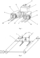
- Fig. 1 shows a battery powered lift truck as invented, which consists of a body 1 to which a drawbar 2 is attached on one side and three pairs of forks on the other side via a lever system.
- the pair of forks 3.1 with longitudinal travel is connected to the body 1 of the forklift truck via the lifting mechanism 5 and the longitudinal travel mechanism 7.
- the pairs of forks 3.2 with transverse travel are movably mounted to the body 1 of the battery powered lift truck by means of cross-type mechanisms 4 enabling their lifting, retracting and extending.
- the side support wheels 6 are located on two elongated arms 1.1 of the body 1 directly behind the pairs of forks 3.2 with transverse travel.
- Figure 2 shows a schematic drawing of the driving mechanisms of the forks 3.1 with longitudinal travel, with the visible lifting mechanism 5 and the longitudinal travel mechanism 7 implemented by means of a belt or chain transmission.
- Fig. 3 shows the battery lift truck with extended forks 3.2 with transverse travel and the forks 3.1 with longitudinal travel with the longitudinal travel mechanism 7 retracted towards the body 1 of the battery powered lift truck.
- the picking up and loading of goods onto the means of transport by the battery powered lift truck as invented takes place in several steps.
- three parallel pallets are picked up at the same time by raising three pairs of forks 3.1, 3.2 simultaneously.
- Figure 4 shows a raised pair of forks 3.1 with longitudinal travel and the extended pair of forks 3.2 with transverse travel.
- Pallets (P) are loaded both on the forks 3.2 with transverse travel and on the forks 3.1 with longitudinal travel.
- the longitudinal travel mechanism 7 (not visible in Fig. 4 ) is retracted and the forks 3.2 with transverse travel are retracted in the direction of the forks 3.1 with longitudinal travel.
- the pallet on the forks 3.1 with longitudinal travel is partially covered by the pallets on the forks 3.2 with transverse travel, and the width of battery powered lift truck is reduced.
- the battery powered lift truck as invented enters a means of transport, e.g. a semi-trailer or the loading part of a truck or other means of transport intended for the transport of goods.
- Figure 5 shows the forks 3.2 with transverse travel and the forks 3.1 with longitudinal travel with the pallets (P), the forks 3.2 with transverse travel being in the retracted position.
- the process of putting down the pallets (P) is done in the opposite way to taking them up.
- the last step is to lower the forks 3.2 with transverse travel and the forks 3.1 with longitudinal travel.
- the cycle is repeated each time until the semi-trailer is properly filled.
- the cross-type mechanisms of forks with transverse travel can be driven, for example, by means of hydraulic cylinders, electric or pneumatic drives.
- the drive and spacing of the pair of forks with longitudinal travel and pairs of forks with transverse travel can be both synchronized and independent, which means that each pair of forks can move a different distance.
- the pair of forks with longitudinal travel can be fixed on the cross-type mechanism which means that the pair of forks with longitudinal travel can be raised and moved laterally over a given distance.
- the invention can be used in all areas, both warehouse and production, speeding up the movement of loads inside plants as well as loading and unloading. This is done by increasing the number of pallets transported in one cycle.
- the system allows the installation of technical components for complete automation of processes.
Landscapes
- Engineering & Computer Science (AREA)
- Transportation (AREA)
- Structural Engineering (AREA)
- Civil Engineering (AREA)
- Life Sciences & Earth Sciences (AREA)
- Geology (AREA)
- Mechanical Engineering (AREA)
- Forklifts And Lifting Vehicles (AREA)
- Handcart (AREA)
Claims (9)
- Un chariot élévateur alimenté par batterie comprenant une carrosserie (1) composée de deux bras allongés (1.1), une unité d'entraînement reliée à un timon ou à un volant ou à un joystick de commande, caractérisé en ce qu'il comprend en outre au moins deux paires parallèles de fourches dont au moins une paire de fourches (3.1) est soulevée et déplacée parallèlement à la carrosserie (1) au moyen d'un système de levage et d'un mécanisme de déplacement longitudinal, et les autres paires de fourches (3.2) sont placées sur les bras allongés (1.1) de la carrosserie (1) et sont montées sur des mécanismes en croix composés de deux mécanismes perpendiculaires : un mécanisme de levage et un mécanisme de déplacement linéaire perpendiculaire à la carrosserie, permettant leur levage, leur rétraction et leur extension, et les bras allongés (1.1) de la carrosserie (1) contiennent des roues d'appui latérales (6).
- Le chariot élévateur alimenté par batterie selon la revendication 1, caractérisé en ce qu'il comprend trois paires de fourches parallèles, dont une paire de fourches (3.1) - celle du milieu - est soulevée et déplacée parallèlement à la carrosserie (1) au moyen d'un système de levage et d'un mécanisme de déplacement longitudinal et les deux autres paires de fourches (3.2) sont placées sur les bras allongés (1.1) de la carrosserie (1) et sont montées sur des mécanismes en croix permettant leur levage, leur rétraction et leur extension dans un sens perpendiculaire à la carrosserie (1), et les bras allongés de la carrosserie (1) contiennent des roues d'appui latérales (6).
- Le chariot élévateur alimenté par batterie selon la revendication 1, caractérisé en ce qu'il comprend trois paires parallèles de fourches, dont une paire de fourches (3.1) - celle du milieu - est reliée à la carrosserie allongée (1) au moyen d'un mécanisme de levage, et les autres paires de fourches (3.2) sont placées sur des rails longitudinaux et sont équipées de mécanismes en croix pour le levage et le déplacement transversal des fourches par rapport à la carrosserie (1), en outre, les guides longitudinaux sont intégrés dans les bras de la carrosserie (1.1) qui contiennent les roues d'appui latérales (6).
- Le chariot élévateur alimenté par batterie selon la revendication 1, caractérisé en ce qu'il comprend trois paires de fourches, dont une paire de fourches (3.1) - celle du milieu - est suspendue à un convoyeur longitudinal par un mécanisme en croix, tandis que les deux autres paires de fourches (3.2) sont reliées à la carrosserie (1) du chariot au moyen de mécanismes en croix permettant leur levage, leur rétraction et leur extension, supportés par des roues d'appui (6).
- Le chariot élévateur alimenté par batterie selon la revendication 1, caractérisé en ce que l'entraînement pour la rétraction et l'extension des fourches à travers les mécanismes en croix est assuré par un cylindre hydraulique, électrique ou pneumatique intégré dans le mécanisme coulissant.
- Le chariot élévateur alimenté par batterie selon la revendication 1, caractérisé en ce que l'entraînement de chaque paire de fourches est indépendant de l'entraînement des autres paires de fourches.
- Le chariot élévateur alimenté par batterie selon la revendication 1, caractérisé en ce que la commande de l'entraînement des fourches (3.2) à déplacement transversal et des fourches (3.1) à déplacement longitudinal est automatisée.
- Le chariot élévateur alimenté par batterie selon la revendication 1, caractérisé en ce que la paire de fourches (3.1) à déplacement longitudinal est suspendue à un guide roulant et est entraînée par un système de câbles situé dans la carrosserie (1) du chariot.
- Le chariot élévateur alimenté par batterie selon la revendication 1, caractérisé en ce que le système d'entraînement du mécanisme de déplacement longitudinal des fourches (3.1) est hydraulique, électrique ou pneumatique.
Priority Applications (2)
| Application Number | Priority Date | Filing Date | Title |
|---|---|---|---|
| RS20241341A RS66249B1 (sr) | 2020-03-23 | 2021-02-22 | Viljuškar sa napajanjem na baterije |
| HRP20241403TT HRP20241403T1 (hr) | 2020-03-23 | 2021-02-22 | Viličar na baterijski pogon |
Applications Claiming Priority (1)
| Application Number | Priority Date | Filing Date | Title |
|---|---|---|---|
| PL433351A PL433351A1 (pl) | 2020-03-23 | 2020-03-23 | Akumulatorowy wózek podnoszący |
Publications (2)
| Publication Number | Publication Date |
|---|---|
| EP3885306A1 EP3885306A1 (fr) | 2021-09-29 |
| EP3885306B1 true EP3885306B1 (fr) | 2024-09-04 |
Family
ID=75277952
Family Applications (1)
| Application Number | Title | Priority Date | Filing Date |
|---|---|---|---|
| EP21460016.5A Active EP3885306B1 (fr) | 2020-03-23 | 2021-02-22 | Chariot élévateur alimenté par batterie |
Country Status (8)
| Country | Link |
|---|---|
| EP (1) | EP3885306B1 (fr) |
| DK (1) | DK3885306T3 (fr) |
| ES (1) | ES2992597T3 (fr) |
| HR (1) | HRP20241403T1 (fr) |
| HU (1) | HUE069244T2 (fr) |
| LT (1) | LT3885306T (fr) |
| PL (1) | PL433351A1 (fr) |
| RS (1) | RS66249B1 (fr) |
Families Citing this family (1)
| Publication number | Priority date | Publication date | Assignee | Title |
|---|---|---|---|---|
| JP7115413B2 (ja) * | 2019-05-07 | 2022-08-09 | トヨタ自動車株式会社 | フォークリフト装置 |
Family Cites Families (2)
| Publication number | Priority date | Publication date | Assignee | Title |
|---|---|---|---|---|
| GB868033A (en) * | 1959-01-23 | 1961-05-17 | Lansing Bagnall Ltd | Improvements in or relating to vehicles |
| DE29620342U1 (de) * | 1996-11-22 | 1998-03-19 | Westfalia-WST-Systemtechnik GmbH & Co. KG, 33829 Borgholzhausen | Satellitenfahrzeug |
-
2020
- 2020-03-23 PL PL433351A patent/PL433351A1/pl unknown
-
2021
- 2021-02-22 HU HUE21460016A patent/HUE069244T2/hu unknown
- 2021-02-22 LT LTEP21460016.5T patent/LT3885306T/lt unknown
- 2021-02-22 RS RS20241341A patent/RS66249B1/sr unknown
- 2021-02-22 DK DK21460016.5T patent/DK3885306T3/da active
- 2021-02-22 EP EP21460016.5A patent/EP3885306B1/fr active Active
- 2021-02-22 HR HRP20241403TT patent/HRP20241403T1/hr unknown
- 2021-02-22 ES ES21460016T patent/ES2992597T3/es active Active
Also Published As
| Publication number | Publication date |
|---|---|
| RS66249B1 (sr) | 2024-12-31 |
| HUE069244T2 (hu) | 2025-02-28 |
| EP3885306A1 (fr) | 2021-09-29 |
| PL433351A1 (pl) | 2021-09-27 |
| ES2992597T3 (en) | 2024-12-16 |
| LT3885306T (lt) | 2024-11-11 |
| DK3885306T3 (da) | 2024-12-02 |
| HRP20241403T1 (hr) | 2024-12-20 |
Similar Documents
| Publication | Publication Date | Title |
|---|---|---|
| US3727778A (en) | Material handling system | |
| JP2620707B2 (ja) | リフトスォーク式荷役装置 | |
| CN105555650B (zh) | 挂车列挂车 | |
| US9249001B2 (en) | Universal load-lifting means for the palletless handling of goods to be loaded onto pallets | |
| US7871232B2 (en) | Line feed system with indexing cart | |
| CN112340653A (zh) | 一种随车装卸货物的机器人 | |
| CN213950488U (zh) | 一种随车装卸货物的机器人 | |
| US20230192425A1 (en) | Apparatus and method for unloading and loading a transport unit | |
| DE19635858A1 (de) | Vorrichtung zum seitlichen Be- und Entladen von Fahrzeugen | |
| US4027823A (en) | Loading-unloading apparatus for a vehicle | |
| EP0000321B1 (fr) | Dispositif de manutention d'objets destiné au chargement et déchargement de véhicules de transport | |
| EP3885306A1 (fr) | Chariot élévateur alimenté par batterie | |
| EP0573380A1 (fr) | Installation pour manoeuvrer des palettes dans des grues à portique | |
| US5039270A (en) | Physically integrated manufacturing and materials handling system | |
| JPH0336738B2 (fr) | ||
| JPH06345397A (ja) | 移載装置付無人搬送車 | |
| CN213387663U (zh) | 一种多层水果筐无托盘装卸、搬运装置 | |
| JP2731417B2 (ja) | 搬送台車 | |
| JP3451031B2 (ja) | 連接する自動倉庫間における横渡し機能付自動倉庫 | |
| DE29620342U1 (de) | Satellitenfahrzeug | |
| EP2918526B1 (fr) | Dispositif pour déplacer des supports de marchandises tels que des palettes | |
| JP2691017B2 (ja) | 搬送台車 | |
| KR100426052B1 (ko) | 화물 적재용 운반차 | |
| US5030055A (en) | Physically integrated manufacturing and materials handling system | |
| CN219751259U (zh) | 一种货物装载机 |
Legal Events
| Date | Code | Title | Description |
|---|---|---|---|
| REG | Reference to a national code |
Ref country code: HR Ref legal event code: TUEP Ref document number: P20241403T Country of ref document: HR |
|
| PUAI | Public reference made under article 153(3) epc to a published international application that has entered the european phase |
Free format text: ORIGINAL CODE: 0009012 |
|
| STAA | Information on the status of an ep patent application or granted ep patent |
Free format text: STATUS: THE APPLICATION HAS BEEN PUBLISHED |
|
| AK | Designated contracting states |
Kind code of ref document: A1 Designated state(s): AL AT BE BG CH CY CZ DE DK EE ES FI FR GB GR HR HU IE IS IT LI LT LU LV MC MK MT NL NO PL PT RO RS SE SI SK SM TR |
|
| STAA | Information on the status of an ep patent application or granted ep patent |
Free format text: STATUS: REQUEST FOR EXAMINATION WAS MADE |
|
| 17P | Request for examination filed |
Effective date: 20220311 |
|
| RBV | Designated contracting states (corrected) |
Designated state(s): AL AT BE BG CH CY CZ DE DK EE ES FI FR GB GR HR HU IE IS IT LI LT LU LV MC MK MT NL NO PL PT RO RS SE SI SK SM TR |
|
| GRAP | Despatch of communication of intention to grant a patent |
Free format text: ORIGINAL CODE: EPIDOSNIGR1 |
|
| STAA | Information on the status of an ep patent application or granted ep patent |
Free format text: STATUS: GRANT OF PATENT IS INTENDED |
|
| INTG | Intention to grant announced |
Effective date: 20240424 |
|
| GRAS | Grant fee paid |
Free format text: ORIGINAL CODE: EPIDOSNIGR3 |
|
| GRAA | (expected) grant |
Free format text: ORIGINAL CODE: 0009210 |
|
| STAA | Information on the status of an ep patent application or granted ep patent |
Free format text: STATUS: THE PATENT HAS BEEN GRANTED |
|
| AK | Designated contracting states |
Kind code of ref document: B1 Designated state(s): AL AT BE BG CH CY CZ DE DK EE ES FI FR GB GR HR HU IE IS IT LI LT LU LV MC MK MT NL NO PL PT RO RS SE SI SK SM TR |
|
| REG | Reference to a national code |
Ref country code: GB Ref legal event code: FG4D |
|
| REG | Reference to a national code |
Ref country code: CH Ref legal event code: EP |
|
| REG | Reference to a national code |
Ref country code: IE Ref legal event code: FG4D |
|
| REG | Reference to a national code |
Ref country code: DE Ref legal event code: R096 Ref document number: 602021018270 Country of ref document: DE |
|
| REG | Reference to a national code |
Ref country code: NL Ref legal event code: FP |
|
| REG | Reference to a national code |
Ref country code: DK Ref legal event code: T3 Effective date: 20241128 |
|
| REG | Reference to a national code |
Ref country code: ES Ref legal event code: FG2A Ref document number: 2992597 Country of ref document: ES Kind code of ref document: T3 Effective date: 20241216 |
|
| REG | Reference to a national code |
Ref country code: HR Ref legal event code: T1PR Ref document number: P20241403 Country of ref document: HR |
|
| REG | Reference to a national code |
Ref country code: SE Ref legal event code: TRGR |
|
| PG25 | Lapsed in a contracting state [announced via postgrant information from national office to epo] |
Ref country code: NO Free format text: LAPSE BECAUSE OF FAILURE TO SUBMIT A TRANSLATION OF THE DESCRIPTION OR TO PAY THE FEE WITHIN THE PRESCRIBED TIME-LIMIT Effective date: 20241204 |
|
| PG25 | Lapsed in a contracting state [announced via postgrant information from national office to epo] |
Ref country code: GR Free format text: LAPSE BECAUSE OF FAILURE TO SUBMIT A TRANSLATION OF THE DESCRIPTION OR TO PAY THE FEE WITHIN THE PRESCRIBED TIME-LIMIT Effective date: 20241205 Ref country code: FI Free format text: LAPSE BECAUSE OF FAILURE TO SUBMIT A TRANSLATION OF THE DESCRIPTION OR TO PAY THE FEE WITHIN THE PRESCRIBED TIME-LIMIT Effective date: 20240904 |
|
| PG25 | Lapsed in a contracting state [announced via postgrant information from national office to epo] |
Ref country code: BG Free format text: LAPSE BECAUSE OF FAILURE TO SUBMIT A TRANSLATION OF THE DESCRIPTION OR TO PAY THE FEE WITHIN THE PRESCRIBED TIME-LIMIT Effective date: 20240904 |
|
| REG | Reference to a national code |
Ref country code: SK Ref legal event code: T3 Ref document number: E 45455 Country of ref document: SK |
|
| PG25 | Lapsed in a contracting state [announced via postgrant information from national office to epo] |
Ref country code: NO Free format text: LAPSE BECAUSE OF FAILURE TO SUBMIT A TRANSLATION OF THE DESCRIPTION OR TO PAY THE FEE WITHIN THE PRESCRIBED TIME-LIMIT Effective date: 20241204 Ref country code: GR Free format text: LAPSE BECAUSE OF FAILURE TO SUBMIT A TRANSLATION OF THE DESCRIPTION OR TO PAY THE FEE WITHIN THE PRESCRIBED TIME-LIMIT Effective date: 20241205 Ref country code: FI Free format text: LAPSE BECAUSE OF FAILURE TO SUBMIT A TRANSLATION OF THE DESCRIPTION OR TO PAY THE FEE WITHIN THE PRESCRIBED TIME-LIMIT Effective date: 20240904 Ref country code: BG Free format text: LAPSE BECAUSE OF FAILURE TO SUBMIT A TRANSLATION OF THE DESCRIPTION OR TO PAY THE FEE WITHIN THE PRESCRIBED TIME-LIMIT Effective date: 20240904 |
|
| REG | Reference to a national code |
Ref country code: HR Ref legal event code: ODRP Ref document number: P20241403 Country of ref document: HR Payment date: 20250115 Year of fee payment: 5 Ref country code: HU Ref legal event code: AG4A Ref document number: E069244 Country of ref document: HU |
|
| PG25 | Lapsed in a contracting state [announced via postgrant information from national office to epo] |
Ref country code: PT Free format text: LAPSE BECAUSE OF FAILURE TO SUBMIT A TRANSLATION OF THE DESCRIPTION OR TO PAY THE FEE WITHIN THE PRESCRIBED TIME-LIMIT Effective date: 20250106 Ref country code: IS Free format text: LAPSE BECAUSE OF FAILURE TO SUBMIT A TRANSLATION OF THE DESCRIPTION OR TO PAY THE FEE WITHIN THE PRESCRIBED TIME-LIMIT Effective date: 20250104 |
|
| PG25 | Lapsed in a contracting state [announced via postgrant information from national office to epo] |
Ref country code: RO Free format text: LAPSE BECAUSE OF FAILURE TO SUBMIT A TRANSLATION OF THE DESCRIPTION OR TO PAY THE FEE WITHIN THE PRESCRIBED TIME-LIMIT Effective date: 20240904 Ref country code: SM Free format text: LAPSE BECAUSE OF FAILURE TO SUBMIT A TRANSLATION OF THE DESCRIPTION OR TO PAY THE FEE WITHIN THE PRESCRIBED TIME-LIMIT Effective date: 20240904 |
|
| PG25 | Lapsed in a contracting state [announced via postgrant information from national office to epo] |
Ref country code: EE Free format text: LAPSE BECAUSE OF FAILURE TO SUBMIT A TRANSLATION OF THE DESCRIPTION OR TO PAY THE FEE WITHIN THE PRESCRIBED TIME-LIMIT Effective date: 20240904 |
|
| REG | Reference to a national code |
Ref country code: DE Ref legal event code: R097 Ref document number: 602021018270 Country of ref document: DE |
|
| PLBE | No opposition filed within time limit |
Free format text: ORIGINAL CODE: 0009261 |
|
| STAA | Information on the status of an ep patent application or granted ep patent |
Free format text: STATUS: NO OPPOSITION FILED WITHIN TIME LIMIT |
|
| 26N | No opposition filed |
Effective date: 20250605 |
|
| PG25 | Lapsed in a contracting state [announced via postgrant information from national office to epo] |
Ref country code: MC Free format text: LAPSE BECAUSE OF FAILURE TO SUBMIT A TRANSLATION OF THE DESCRIPTION OR TO PAY THE FEE WITHIN THE PRESCRIBED TIME-LIMIT Effective date: 20240904 |
|
| PG25 | Lapsed in a contracting state [announced via postgrant information from national office to epo] |
Ref country code: LU Free format text: LAPSE BECAUSE OF NON-PAYMENT OF DUE FEES Effective date: 20250222 |
|
| REG | Reference to a national code |
Ref country code: AT Ref legal event code: UEP Ref document number: 1720228 Country of ref document: AT Kind code of ref document: T Effective date: 20240904 |
|
| PG25 | Lapsed in a contracting state [announced via postgrant information from national office to epo] |
Ref country code: IE Free format text: LAPSE BECAUSE OF NON-PAYMENT OF DUE FEES Effective date: 20250222 |
|
| REG | Reference to a national code |
Ref country code: HR Ref legal event code: ODRP Ref document number: P20241403 Country of ref document: HR Payment date: 20260123 Year of fee payment: 6 |
|
| REG | Reference to a national code |
Ref country code: CH Ref legal event code: U11 Free format text: ST27 STATUS EVENT CODE: U-0-0-U10-U11 (AS PROVIDED BY THE NATIONAL OFFICE) Effective date: 20260301 |
|
| PGFP | Annual fee paid to national office [announced via postgrant information from national office to epo] |
Ref country code: NL Payment date: 20260227 Year of fee payment: 6 |
|
| PGFP | Annual fee paid to national office [announced via postgrant information from national office to epo] |
Ref country code: HU Payment date: 20260209 Year of fee payment: 6 |
|
| PGFP | Annual fee paid to national office [announced via postgrant information from national office to epo] |
Ref country code: SE Payment date: 20260219 Year of fee payment: 6 |
|
| PGFP | Annual fee paid to national office [announced via postgrant information from national office to epo] |
Ref country code: GB Payment date: 20260130 Year of fee payment: 6 Ref country code: LT Payment date: 20260123 Year of fee payment: 6 |
|
| PGFP | Annual fee paid to national office [announced via postgrant information from national office to epo] |
Ref country code: ES Payment date: 20260312 Year of fee payment: 6 |
|
| PGFP | Annual fee paid to national office [announced via postgrant information from national office to epo] |
Ref country code: DK Payment date: 20260220 Year of fee payment: 6 Ref country code: DE Payment date: 20260220 Year of fee payment: 6 |
|
| PGFP | Annual fee paid to national office [announced via postgrant information from national office to epo] |
Ref country code: HR Payment date: 20260123 Year of fee payment: 6 Ref country code: AT Payment date: 20260223 Year of fee payment: 6 |
|
| PGFP | Annual fee paid to national office [announced via postgrant information from national office to epo] |
Ref country code: BE Payment date: 20260227 Year of fee payment: 6 Ref country code: IT Payment date: 20260217 Year of fee payment: 6 |
|
| PGFP | Annual fee paid to national office [announced via postgrant information from national office to epo] |
Ref country code: RS Payment date: 20260209 Year of fee payment: 6 |
|
| PGFP | Annual fee paid to national office [announced via postgrant information from national office to epo] |
Ref country code: FR Payment date: 20260129 Year of fee payment: 6 |
|
| PGFP | Annual fee paid to national office [announced via postgrant information from national office to epo] |
Ref country code: CZ Payment date: 20260216 Year of fee payment: 6 Ref country code: CH Payment date: 20260301 Year of fee payment: 6 |
|
| PGFP | Annual fee paid to national office [announced via postgrant information from national office to epo] |
Ref country code: PL Payment date: 20260204 Year of fee payment: 6 |
|
| PGFP | Annual fee paid to national office [announced via postgrant information from national office to epo] |
Ref country code: SK Payment date: 20260128 Year of fee payment: 6 Ref country code: LV Payment date: 20260123 Year of fee payment: 6 |