EP3885497B1 - Unité de boîtier de raccordement destinée à être encastrée pourvu de manchon d'extension - Google Patents
Unité de boîtier de raccordement destinée à être encastrée pourvu de manchon d'extension Download PDFInfo
- Publication number
- EP3885497B1 EP3885497B1 EP21164305.1A EP21164305A EP3885497B1 EP 3885497 B1 EP3885497 B1 EP 3885497B1 EP 21164305 A EP21164305 A EP 21164305A EP 3885497 B1 EP3885497 B1 EP 3885497B1
- Authority
- EP
- European Patent Office
- Prior art keywords
- sleeve
- retaining
- extension sleeve
- box unit
- connection box
- Prior art date
- Legal status (The legal status is an assumption and is not a legal conclusion. Google has not performed a legal analysis and makes no representation as to the accuracy of the status listed.)
- Active
Links
Images


Classifications
-
- E—FIXED CONSTRUCTIONS
- E03—WATER SUPPLY; SEWERAGE
- E03C—DOMESTIC PLUMBING INSTALLATIONS FOR FRESH WATER OR WASTE WATER; SINKS
- E03C1/00—Domestic plumbing installations for fresh water or waste water; Sinks
- E03C1/02—Plumbing installations for fresh water
- E03C1/04—Water-basin installations specially adapted to wash-basins or baths
-
- E—FIXED CONSTRUCTIONS
- E03—WATER SUPPLY; SEWERAGE
- E03C—DOMESTIC PLUMBING INSTALLATIONS FOR FRESH WATER OR WASTE WATER; SINKS
- E03C1/00—Domestic plumbing installations for fresh water or waste water; Sinks
- E03C1/02—Plumbing installations for fresh water
- E03C1/021—Devices for positioning or connecting of water supply lines
-
- E—FIXED CONSTRUCTIONS
- E03—WATER SUPPLY; SEWERAGE
- E03C—DOMESTIC PLUMBING INSTALLATIONS FOR FRESH WATER OR WASTE WATER; SINKS
- E03C1/00—Domestic plumbing installations for fresh water or waste water; Sinks
- E03C1/02—Plumbing installations for fresh water
-
- H—ELECTRICITY
- H02—GENERATION; CONVERSION OR DISTRIBUTION OF ELECTRIC POWER
- H02G—INSTALLATION OF ELECTRIC CABLES OR LINES, OR OF COMBINED OPTICAL AND ELECTRIC CABLES OR LINES
- H02G3/00—Installations of electric cables or lines or protective tubing therefor in or on buildings, equivalent structures or vehicles
- H02G3/02—Details
- H02G3/08—Distribution boxes; Connection or junction boxes
- H02G3/081—Bases, casings or covers
-
- E—FIXED CONSTRUCTIONS
- E03—WATER SUPPLY; SEWERAGE
- E03B—INSTALLATIONS OR METHODS FOR OBTAINING, COLLECTING, OR DISTRIBUTING WATER
- E03B7/00—Water main or service pipe systems
- E03B7/09—Component parts or accessories
- E03B7/095—Component holders or housings, e.g. boundary boxes
-
- E—FIXED CONSTRUCTIONS
- E03—WATER SUPPLY; SEWERAGE
- E03C—DOMESTIC PLUMBING INSTALLATIONS FOR FRESH WATER OR WASTE WATER; SINKS
- E03C1/00—Domestic plumbing installations for fresh water or waste water; Sinks
- E03C1/02—Plumbing installations for fresh water
- E03C1/04—Water-basin installations specially adapted to wash-basins or baths
- E03C1/042—Arrangements on taps for wash-basins or baths for connecting to the wall
-
- E—FIXED CONSTRUCTIONS
- E04—BUILDING
- E04F—FINISHING WORK ON BUILDINGS, e.g. STAIRS, FLOORS
- E04F17/00—Vertical ducts; Channels, e.g. for drainage
- E04F17/08—Vertical ducts; Channels, e.g. for drainage for receiving utility lines, e.g. cables, pipes
-
- F—MECHANICAL ENGINEERING; LIGHTING; HEATING; WEAPONS; BLASTING
- F16—ENGINEERING ELEMENTS AND UNITS; GENERAL MEASURES FOR PRODUCING AND MAINTAINING EFFECTIVE FUNCTIONING OF MACHINES OR INSTALLATIONS; THERMAL INSULATION IN GENERAL
- F16L—PIPES; JOINTS OR FITTINGS FOR PIPES; SUPPORTS FOR PIPES, CABLES OR PROTECTIVE TUBING; MEANS FOR THERMAL INSULATION IN GENERAL
- F16L39/00—Joints or fittings for double-walled or multi-channel pipes or pipe assemblies
-
- F—MECHANICAL ENGINEERING; LIGHTING; HEATING; WEAPONS; BLASTING
- F16—ENGINEERING ELEMENTS AND UNITS; GENERAL MEASURES FOR PRODUCING AND MAINTAINING EFFECTIVE FUNCTIONING OF MACHINES OR INSTALLATIONS; THERMAL INSULATION IN GENERAL
- F16L—PIPES; JOINTS OR FITTINGS FOR PIPES; SUPPORTS FOR PIPES, CABLES OR PROTECTIVE TUBING; MEANS FOR THERMAL INSULATION IN GENERAL
- F16L41/00—Branching pipes; Joining pipes to walls
-
- H—ELECTRICITY
- H02—GENERATION; CONVERSION OR DISTRIBUTION OF ELECTRIC POWER
- H02G—INSTALLATION OF ELECTRIC CABLES OR LINES, OR OF COMBINED OPTICAL AND ELECTRIC CABLES OR LINES
- H02G3/00—Installations of electric cables or lines or protective tubing therefor in or on buildings, equivalent structures or vehicles
- H02G3/02—Details
- H02G3/08—Distribution boxes; Connection or junction boxes
- H02G3/12—Distribution boxes; Connection or junction boxes for flush mounting
Definitions
- the invention relates to a wall-mounted connection box unit comprising a box housing body with a rear base section and a sleeve section projecting forward from the base section, which sleeve section circumferentially surrounds a built-in component receiving space accessible via an open front end of the sleeve section, an extension sleeve which is configured for coaxial arrangement on the sleeve section and axially retractable relative to the sleeve section, and a holding structure which allows axial retraction of the extension sleeve on the sleeve section from an assembly position into an end-use position at a variable axial height and holds the extension sleeve on the sleeve section in the end-use position.
- junction box units are used, for example, in sanitary installation technology for connecting built-in components in the form of sanitary components such as water outlet fittings for washbasins, bathtubs, shower heads or kitchen sinks or upstream sanitary thermostat, mixer and/or shut-off valve units to pre-installed water pipe connections in the building, and in electrical installation technology for connecting electrical built-in components such as sockets, junction boxes, sensors, actuators, light switches, etc. to pre-installed electrical cable connections in the building.
- Flush-mounted versions are particularly typical in this case, in which the wall-mounted junction box unit is installed in the relevant building wall in such a way that its front is as flush as possible with the finished building wall surface, e.g. a plastered wall surface or a tiled wall surface.
- the building wall can be both a vertical building wall in the narrower sense and a floor wall or floor surface or a ceiling wall or ceiling surface of a building or room, in the sanitary case, for example, a shower room, a bathroom, a toilet room, a kitchen, etc.
- a connector body arranged in the rear base section of the box housing body typically serves as the connecting link for connecting the built-in component to the building's line connections.
- the base section is configured accordingly for arranging or holding the connector body.
- the connector body has a built-in component connection contour facing the built-in component receiving space and a line connection interface structure accessible on an outer side of the box housing body.
- the line connection interface structure typically includes one or more connection interfaces, in the sanitary case a fluid line connection interface structure in particular in the form of corresponding pipe connection nozzles for coupling to a corresponding building-side pipe connection nozzle, e.g. for cold water, hot water or mixed water made up of cold water and hot water, in the electrical case an electrical line connection interface structure in particular in the form of cable line connections.
- the connector body includes a fluid channel structure for fluidly connecting the fluid line connection interface structure on the outside of the box to the sanitary component connection contour on the inside of the box; in the electrical case, it includes an electrically conductive connection between the electrical line connection interface structure on the outside of the box and the electrical component connection contour on the inside of the box.
- the junction box unit is inserted with its rear side or rear base first into a building wall opening or is placed against a building wall, e.g. a drywall wall, whereby the required cable connections are established between the building-side connections on the one hand and the connection interface structure of the junction box on the other.
- the Installation component is inserted into the receiving space of the box housing body and coupled to the appropriate connection contour of the connection body.
- junction box unit A known problem with the wall mounting of such and similar junction box units is that the position of the junction box unit in relation to the finished building wall surface, in particular with regard to its installation depth in the case of flush-mounted installation, is not yet precisely specified as long as the building wall is not yet finished, in particular not yet plastered, tiled or otherwise clad.
- connection box units of the type considered here by the extension sleeve, which, using the holding structure, is arranged telescopically and movably on the sleeve section of the box housing body, i.e., it is arranged coaxially on the sleeve section and guided axially height-adjustable on it and relative to it, and can be held in a variably predeterminable, desired axial position on the sleeve section.
- the extension sleeve can be pushed back from an initial assembly position to a final end-of-use position by a variable axial amount, i.e., toward the base section of the box housing body or toward greater axial overlap with the sleeve section.
- the extension sleeve can not only be moved back axially unidirectionally, but can also be moved forward bidirectionally, i.e., away from the base section of the box housing body or toward less axial overlap with the sleeve section.
- the extension sleeve is guided on the inner or outer circumference of the sleeve section. In the former case, it has a suitably smaller outer diameter than the inner diameter of the sleeve section and is circumferentially surrounded by the sleeve section. In the latter case, it has a suitably larger inner diameter than the outer diameter of the sleeve section and circumferentially surrounds the sleeve section.
- the extension sleeve is first held in the mounting position, which is a position that protrudes sufficiently far forward beyond the sleeve section, which ensures that the connection box unit, after its wall mounting, can be
- the extension sleeve extends forward at least as far as the planned finished building wall surface, preferably protruding forward beyond it and in any case not remaining behind it.
- the extension sleeve if or to the extent that it protrudes beyond the surface of the completed building wall in its installed position, can be pushed back axially into a position ultimately desired for use of the junction box unit after completion of the building wall surface, preferably until the front is flush or almost flush with the finished wall surface.
- This ultimately desired position of the extension sleeve therefore represents its respective final use position, the axial height of which relative to the sleeve section of the box housing body can vary depending on the resulting height level of the finished wall surface measured perpendicular to the wall surface.
- the holding structure allows this axial retraction of the extension sleeve on the sleeve section from the assembly position to the final use position at a variable axial height and ensures that the extension sleeve is held sufficiently securely on the sleeve section in the final use position.
- the disclosure document DE 10 2012 203 393 A1 discloses a wall-mounted connection box unit of the type mentioned at the outset, in which the extension sleeve, referred to there as a sleeve, is guided with its outer shell side on the inner shell side of the sleeve section of the box housing body in an axially continuously height-adjustable manner and the holding structure for this purpose includes a sealing ring which is received in an outer sealing ring receptacle of the sleeve, projecting radially outwards, so that it bears against the inner side of the sleeve section of the box housing body with a certain surface pressure in order to provide a continuously adjustable and sealing, frictionally engaged connection between the sleeve and the sleeve section of the box housing body.
- WO 2017/091839 A1 discloses a wall-mounted connection box unit of the type mentioned above, in which the axially height-adjustable extension sleeve is designed as a mounting sleeve which, at its free front
- the front end has a fastening means for attaching an add-on component, such as a sanitary mixer fitting
- the holding structure includes cooperating locking web structures, which are continuous along the circumference or formed only in segmental areas, on the mounting sleeve on the one hand and on the sleeve section of the box housing body on the other hand, whereby the mounting sleeve can be held locked in a stepped manner at several different axial height levels on the sleeve section of the box housing body.
- the locking can be locked by means of an additionally inserted securing sleeve.
- US 2017/0256930 A1 discloses a wall-mounted connection box unit for use in electrical installations, comprising a box housing body made of a metal material, alternatively a plastic material, which has a sleeve portion protruding from a base portion, and comprising an extension sleeve that can be axially inserted into the sleeve portion in a first rotational position and then, by rotating it into a second rotational position, can be axially fixed to the sleeve portion at a variable height in the manner of a bayonet lock.
- the patent specification NO 336337 B1 discloses a wall-mounted connection box unit of the type mentioned at the outset, wherein the extension sleeve is manufactured as a two-component adjusting ring with a fastening ring part and a sealing ring part made of a same elastic material and a ring body part made of a non-elastic material and the holding structure includes a wedge ring which can be connected to the adjusting ring by means of screws and can be pressed axially against its fastening ring part, whereby the latter is pressed radially outwards against a grooved inner circumference of the sleeve section of the box housing body.
- EP 2 822 121 A2 discloses a wall-mounted connection box unit of the type mentioned above, which includes two extension sleeves which can be plugged into one another and rotated relative to one another via cooperating threads, wherein The threads are traversable, so that one extension sleeve can be inserted telescopically into the other extension sleeve as an alternative to screwing it in.
- the outer extension sleeve is made of a thinner and/or more flexible material than the extension sleeve attached to the sleeve section.
- connection box units of a similar type are described in the utility model CN 204732809 U and the disclosure document EP 3 703 207 A1 revealed.
- the invention is based on the technical problem of providing a wall-mounted connection box unit of the type mentioned at the outset, which offers, in particular, functional advantages and/or advantages with regard to manufacturing and/or assembly costs compared to the above-mentioned prior art.
- the invention solves this problem by providing a wall-mounted junction box unit with the features of claim 1.
- Advantageous developments of the invention are specified in the subclaims, the wording of which is hereby incorporated by reference into the description. This includes, in particular, all embodiments of the invention resulting from the combinations of features defined by the references in the subclaims.
- the holding structure includes a holding bead structure projecting radially from the sleeve portion, which is formed from a sealingly flexible material in one piece with at least one adjacent axial portion of the sleeve portion made of the sealingly flexible material, and a counter-holding structure which cooperates frictionally and/or positively with the holding bead structure and which is formed on the extension sleeve from a material which is stiffer than the sealingly flexible material.
- the retaining bead structure is made of a sealingly flexible material, it can ensure a desired fluid-tight connection between the extension sleeve and the sleeve section of the box housing body through frictional and/or positive engagement with the stiffer counter-holding structure on the extension sleeve, without the need for additional, separate sealing measures.
- a rubber material or a plastic foam material can be used for the retaining bead structure.
- the material connection of the sealingly flexible, softer material on the one hand and the stiffer material on the other hand can provide a connection between the extension sleeve and the sleeve section that is both reliably sealing and reliably frictionally and/or positively retaining, which also allows for the telescopic axial height adjustment of the extension sleeve on the sleeve section of the box housing body.
- the stiffer material of the counter-holding structure can, for example, be a plastic material that is stiffer than the material of the retaining bead structure or a metal material.
- the extension sleeve can be formed entirely from the material of the counter-holding structure or only in the area of the counter-holding structure.
- this embodiment of the retaining structure according to the invention allows for stepless height adjustment of the extension sleeve relative to the sleeve section of the box housing body, if required.
- the wall-mounted connection box unit comprises a removable spacer element which can be removably attached to the box housing body in a securing position in which it secures the extension sleeve in the mounting position against axial retraction.
- the junction box unit can be secured, in particular, against unintentional axial retraction of the extension sleeve relative to the sleeve section of the box housing body before and/or during assembly of the junction box unit.
- This can be advantageously used to install the extension sleeve in the delivery state of the junction box unit after its manufacture or at least before the junction box unit is installed in or on a building wall. is attached, to be secured in the assembly position on the sleeve section of the box housing body against being pushed back, whereby this assembly position can be, for example, a position in which the extension sleeve protrudes as far forward as possible beyond the sleeve section.
- the spacer element is then removed, i.e. removed, at the latest after the wall surface of the building wall has been finished and the extension sleeve is to be pushed back from its assembly position to its final use position, in which its front end or edge is, for example, essentially flush with the finished wall surface, after which the extension sleeve can be pushed back axially by the desired amount.
- the removal or removal of the spacer element from the box housing body can be carried out non-destructively or with destruction of the spacer element, depending on the design. In the former case, it can be reused if necessary; in the latter case, it is designed as a disposable component that can be removed without being destroyed.
- the retaining bead structure includes a circumferentially continuous retaining bead that protrudes radially inward on an inner side of the sleeve portion or radially outward on an outer side of the sleeve portion.
- the retaining bead extends continuously over the entire circumference of the sleeve portion and can thus ensure both secure retention of the extension sleeve to the sleeve portion of the box housing body and reliable sealing of the connection between the sleeve portion and the extension sleeve.
- the extension sleeve preferably has a structured or profiled surface area that promotes the sealing hold on the sleeve section in cooperation with the retaining bead.
- the outer or inner sleeve surface of the extension sleeve is sufficient as a counter-holding structure that cooperates with the retaining bead.
- the retaining bead can form a sealing contact against the stiffer material of the counter-holding structure in the corresponding profiled or non-profiled surface area of the extension sleeve.
- the retaining bead structure contains only a single such retaining bead or any plurality of such retaining beads arranged at an axial distance from one another.
- the retaining bead structure is formed from a plastic foam material, in particular a thermoplastic particle foam material.
- a plastic foam material in particular a thermoplastic particle foam material.
- the plastic foam material enables the functional properties required for the retaining bead structure to be provided in a technically simple manner with regard to sufficiently axially displaceable guidance and secure holding of the extension sleeve on the sleeve section and with regard to a fluid-tight connection between the extension sleeve and the sleeve section.
- the retaining bead structure can also be formed, for example, from a sealing rubber material or another material known per se to those skilled in the art for sealing similar connections.
- the counterholding structure includes a retaining tooth structure with a plurality of axially successive retaining teeth, which protrude radially outwards on the outer side of the extension sleeve or radially inwards on the inner side of the extension sleeve.
- the counterholding structure can engage with its retaining teeth in the sealingly flexible material of the retaining bead structure and in this way very simply and reliably ensure mechanically secure holding and fluidically secure sealing of the extension sleeve with respect to the sleeve section of the box housing body.
- the extension sleeve can be very easily and variably and preferably steplessly adjusted axially on the sleeve section, in particular pushed back, and in this way can be adjusted to its respectively desired optimal End-use position on the sleeve section of the box housing body and keep it reliably sealed.
- the retaining tooth structure with its retaining teeth forms a sawtooth profile with flatter tooth rear flanks pointing in the direction of retraction of the extension sleeve and opposing, steeper tooth front flanks.
- This special design of the retaining teeth makes it more difficult to move the extension sleeve forward from the final use position than to move it back from the assembly position to the final use position, thereby achieving the desirable effect of preventing the extension sleeve from moving forward from its final use position or at least making it more difficult compared to the force required to push the extension sleeve back from its assembly position to its final use position.
- the retaining tooth structure is arranged at an axial distance from a rear end of the extension sleeve, and a section of the extension sleeve extending axially from the rear end up to at most the retaining tooth structure forms a pre-assembly plug-in area designed to hold the extension sleeve in its pre-assembled, plugged-in position on the sleeve section of the box housing body.
- the retaining tooth structure does not yet need to be in operative connection with the retaining bead structure on the extension sleeve, so that the connection between the retaining tooth structure and the retaining bead structure is not subjected to any stress as long as the extension sleeve has not yet been pushed back into its final use position.
- the pre-assembly plug-in area can, for example, simply be formed by a non-specifically profiled front end area of the inner or outer surface of the extension sleeve; alternatively, it can additionally have a profile that supports the temporary holding of the extension sleeve on the sleeve section of the box housing body in the assembly position.
- the extension sleeve has a radially outwardly projecting end ring flange at a front end.
- the end ring flange can be used for a variety of applications, such as attaching a cover rosette or as a ring stop for resting against the finished surface of the building wall in the final use position of the extension sleeve.
- the extension sleeve ends at the front end without a radially protruding ring flange.
- a mounting cover can be removably attached to a front end of the extension sleeve, e.g., by simply plugging and unplugging.
- the mounting cover can be used, for example, to protect the interior of the extension sleeve and the sleeve section of the box housing body from contamination before and/or during wall mounting of the junction box unit.
- it can be used, if necessary, to hold or apply a spirit level, bubble level, or circular bubble.
- it preferably has a corresponding spirit level support structure or bubble level holder on the outside.
- the mounting cover has a preferably central grip pin on the outside as a handling aid for the user.
- the spacer element includes a spacer sleeve, which, in the secured position, is arranged coaxially on the sleeve section in an axial region behind the extension sleeve.
- the spacer sleeve can be removably inserted into the sleeve section and circumferentially surrounded by it if the extension sleeve is guided on the inner circumference of the sleeve section, or alternatively, it can be removably arranged on the sleeve section, surrounding it circumferentially, if the extension sleeve is guided on the outer circumference of the sleeve section.
- the spacer sleeve is designed in such a way that it can be manufactured with little effort and allows easy attachment and preferably non-destructive removal from the box housing body.
- the spacer sleeve can be designed as a disposable sleeve that can be removed without destruction.
- the spacer sleeve can be made of any material that allows the mentioned properties and requires little implementation effort, e.g., from a suitably elastically or inelastically deformable material, such as cardboard or a Flexible plastic.
- the spacer sleeve can be formed by a circumferentially continuous, closed sleeve part or, alternatively, by a circumferentially open sleeve part with a continuous axial slot, i.e., an open sleeve part extending only over a circumferential angle of less than 360°.
- the only essential requirement in each case is that the spacer sleeve withstands any axial pressure exerted by the extension sleeve before and/or during wall mounting of the junction box unit, in order to hold the extension sleeve in its installed position even when an axial pressure force acts on the front end of the extension sleeve.
- the spacer element includes, for example, a blocking pin that protrudes radially from the sleeve section of the box housing body, preferably in a removable manner, which blocks the axial movement path of the extension sleeve, or a detachable clip connection with which the extension sleeve is held clipped to the sleeve section in its assembly position.
- the spacer sleeve is designed as a circumferentially open, contractible annular sleeve and has a user-operable closing actuation structure.
- This allows the user to very easily and non-destructively insert the spacer sleeve into the sleeve section of the box housing body and/or remove the spacer sleeve from the sleeve section by grasping the open annular sleeve at the closing actuation structure, which acts as a handling aid, e.g., with the fingers of one hand, and radially compressing it, i.e., contracting it, so that its radial expansion is reduced compared to its position in use in the sleeve section.
- the spacer sleeve has a radially inwardly projecting flange structure at a front end.
- This flange structure can be used, for example, as a stop surface against which the extension sleeve rests when it is plugged into the sleeve section of the box housing body to be brought into its assembly position. The flange structure then prevents the extension sleeve from moving further axially backward into the sleeve section of the box housing body.
- Flange structure can also function as the mentioned closing operation structure for the user if required.
- the inventive wall-mounted connection box unit comprises a box housing body 1 with a rear base portion 2 and a sleeve portion 3 projecting forward from the base portion, an extension sleeve 6 and a holding structure 7.
- the sleeve section 3 of the box housing body 1 surrounds a built-in component receiving space 4 accessible via an open front end 5 of the sleeve section 3, as can be seen, for example, from the Fig. 1 to 3
- the extension sleeve 6 is designed for coaxial arrangement on the sleeve section 3 and axial retraction relative to the sleeve section 3.
- the holding structure 7 allows axial retraction of the extension sleeve 6 on the sleeve section 3 from a position in the Fig. 1 , 3 and 8 visible mounting position M S into a position in the Fig. 1 and 8 to be recognized end use position E S and holds the extension sleeve 6 in the end use position E S on the sleeve section 3.
- the assembly position M S is preferably a position of the extension sleeve 6 on the sleeve section 3 in which the extension sleeve 6, on the one hand, protrudes far enough beyond the sleeve section 3 of the box housing body 1 to continue to protrude beyond the relevant building wall surface during and after completion of the latter and in any case not to fall short of its final surface height level, and, on the other hand, is held sufficiently securely pre-assembled on the sleeve section 3 in that it already has a certain axial overlap with the sleeve section 3.
- the final use position E S is located at a variable axial height H E , ie the extension sleeve 6 can be brought into its final use position E S at this desired axial height H E variably relative to the sleeve section 3 of the box housing body 1 and held there by the holding structure 7 secured against unintentional axial movement.
- Fig. 1 and 8 two different end-use positions E S , whereby the extension sleeve 6 in the case of Fig. 8 in a more forward end-use position E S than in the case of Fig. 1 , ie a front end face 6d of the extension sleeve 6 is located relative to the sleeve section 2 of the box housing body 1 in the case of Fig.
- the holding structure 7 includes, as in the exemplary embodiments shown, a holding bead structure 7a projecting radially from the sleeve section 3, which is formed integrally with at least one adjacent axial partial region 3a of the sleeve section 3 from a sealingly flexible material, and a counter-holding structure 7b that interacts with the holding bead structure 7a and is formed on the extension sleeve 6 from a material that is stiffer than the sealingly flexible material.
- This axial partial region 3a of the sleeve section 3 can be any partial region of the sleeve section 3 of any axial extent that also includes the holding bead structure 7a.
- the sleeve section 3 can be formed entirely from the sealingly flexible material; in corresponding implementations, the box housing body 1 is formed entirely from this material.
- the holding structure 7 advantageously enables, with relatively little implementation effort, a sufficiently secure holding of the extension sleeve 6 in its respectively desired final use position ES on the sleeve section 3 of the box housing body 1 and a sufficiently sealing connection of the extension sleeve 6 to the sleeve section 3 of the box housing body 1 by frictional engagement and/or positive engagement.
- the wall-mounted connection box unit comprises a spacer element 8 which is detachably attachable to the box housing body 1 in a securing position S S , in which it secures the extension sleeve 6 in the mounting position M S against axial retraction, ie axial displacement in a retraction direction Z R , as can be seen from Fig. 3
- This can be used in particular to protect the extension sleeve 6 before and during the wall mounting of the junction box unit from unwanted, premature pushing back from its mounting position M S.
- this securing be removed by detaching the spacer element 8 from the box housing body 1, ie removing it.
- both of the above-mentioned aspects of the invention are realized with regard to the formation of the holding structure 7 as a holding bead structure 7a and with regard to the temporarily used spacer element 8. In alternative embodiments, only one of these two aspects of the invention is realized.
- the wall-mounted connection box unit shown can be configured in particular as a sanitary wall-mounted connection box unit for connecting sanitary components to building-side water pipe connections, as explained above, wherein the sleeve section 3 of the box housing body 1 circumferentially surrounds a built-in component receiving space 4, which is then configured as a sanitary component receiving space, which is accessible via an open front end 5 of the sleeve section 3 or the extension sleeve 6, via which the built-in component, such as a sanitary component, can be introduced into the box housing body 1, such as, for example, in the Fig. 1 and 8 visible.
- the wall-mounted connection box unit is configured as an electrical wall-mounted connection box unit for connecting electrical components to building-side electrical line connections, as also explained above, wherein the built-in component receiving space 4 then forms an electrical component receiving space into which the relevant electrical component can be introduced into the box housing body 1 via the open front end 5 of the sleeve section 3.
- a connection body 14 arranged or held in the base section 2 acts as a fluid or line-connecting link, which has a built-in component connection contour 15 facing the built-in component receiving space 4, i.e. in the sanitary case a sanitary component connection contour and in the electrical case an electrical component connection contour, a line connection interface structure 16 accessible on an outer side of the box housing body 1, i.e.
- the retaining bead structure 7a includes a retaining bead 9 that extends continuously around the circumference and, as shown, projects radially inward on an inner side 3b of the sleeve section 3 or, alternatively, radially outward on an outer side 3c of the sleeve section 3.
- the retaining bead structure 7a includes only a single retaining bead 9; in alternative embodiments, it includes a plurality of retaining beads that extend continuously around the circumference and are axially spaced from one another.
- the retaining bead structure 7a is formed from a plastic foam material, which can in particular be a thermoplastic particle foam material, such as a polypropylene particle foam.
- the retaining bead structure 7a is formed from another sealingly flexible material, e.g., a sealing rubber material.
- not only the retaining bead structure 7a, but also the sleeve section 3 or the box housing body 1 is formed from this plastic foam material.
- the box housing body 1 is formed entirely in one piece, e.g., from a plastic foam material, alternatively from another sealingly flexible material, wherein the connecting body 14 is embedded in the plastic foam material of the base section 2 of the box housing body 1.
- the counter-holding structure 7b includes a holding tooth structure 10 with a plurality of axially successive holding teeth 11, which extend circumferentially on an outer side 6a of the extension sleeve 6, as shown, radially outwardly or alternatively radially inwardly on an inner side 6b of the extension sleeve 6.
- the holding teeth 11 consisting of the stiffer material of the counter-holding structure 7b can engage in the sealingly flexible material of the holding bead structure 7a or can be This results in a very secure and well-sealed holding of the extension sleeve 6 on the sleeve section 2 of the box housing body 1 in the end-use position ES , both through this positive engagement and through the frictional engagement provided by the pressing contact of the retaining bead structure 7a against the counter-holding structure 7b made of the stiffer material. Furthermore, this design of the counter-holding structure 7b enables a practically stepless selection of the axial height of the end-use position ES for the extension sleeve 6 on the sleeve section 2.
- the counterholding structure 7b can be formed by a differently structured or profiled surface area of the extension sleeve 6, e.g., a wave-shaped profile or ribbing.
- the counterholding structure 7b is formed solely by the non-structured outer or inner sleeve surface on the outer side 6a or the inner side 6b of the extension sleeve 6.
- the retaining tooth structure 10 with its retaining teeth 11 has a sawtooth profile with flatter tooth rear flanks 11a pointing in the pushing-back direction Z R of the extension sleeve 6 and opposite, steeper tooth front flanks 11b, as in the example shown and as can be seen in particular from Fig. 6
- This design of the retaining tooth structure 10 provides a higher resistance to advancing, ie outward, the extension sleeve 6 in the opposite direction compared to the pushing-back force required to push back the extension sleeve 6 in the pushing-back direction Z R.
- the retaining bead structure 7a such as the retaining bead 9 can slide relatively easily onto the retaining tooth structure 10 when the extension sleeve 6 is pushed back from its assembly position M S into its final use position E S , while the retaining teeth 11 with their steeper tooth front flanks 11b engage more strongly in the retaining bead structure 7b, such as the retaining bead 9, and claw into it in a locking manner when an attempt is made to push the extension sleeve 6 axially out of the final use position E S against the pushing-back direction Z R relative to the holding section 2 of the box housing body 1 to move forward, ie to move in the direction out of the sleeve section 2 of the box housing body 1.
- the holding tooth structure 7b with its holding teeth 11 can have a different type of tooth profile, e.g. a triangular tooth profile symmetrical with respect to the axial sleeve displacement direction without a preferred direction of movement of the extension sleeve 6 axially backwards.
- the retaining tooth structure 10 is arranged at an axial distance from a rear end 6c of the extension sleeve 6, and a section of the extension sleeve 6 extending axially from the rear end 6c up to at most the retaining tooth structure 10 forms a pre-assembly plug-in area 12 which is designed to hold the extension sleeve 6 in its pre-assembled plug-in position MS on the sleeve section 2 of the box housing body 1.
- the pre-assembly plug-in area 12 of the extension sleeve 6 interacts with the retaining bead structure 10, such as the retaining bead 9, as can be seen in particular in the Fig. 1 and 3 visible.
- the retaining bead structure 10 rests on the outside against the pre-assembly plug-in area 12, whereby the extension sleeve 6 is held in its assembled position MS on the sleeve section 2 primarily by means of frictional engagement.
- the retaining tooth structure 10 Since the pre-assembly plug-in area 12 lies axially behind the retaining tooth structure 10, the retaining tooth structure 10 is not yet in operative engagement with the retaining bead structure 7a in the assembled position MS of the extension sleeve 6. This has the consequence that the extension sleeve 6 can, if necessary, be moved outwards again from its assembled position MS on the sleeve section 2, i.e. moved away, or removed from the sleeve section 2 relatively easily, i.e. with comparatively little force required, whereas moving the extension sleeve 6 out of its final use position ES preferably requires a significantly greater expenditure of force or is no longer possible at all without damaging the retaining bead structure 7a.
- the extension sleeve 6 as in the example shown, has a radially outwardly projecting end ring flange 13 at its front, free, open end 6d. This can be used, for example, as a stop surface with which the extension sleeve 6 comes into contact with a finished building wall surface when the extension sleeve 6 is pushed back into its final use position ES .
- an optional mounting cover 17 can be attached to the front end 6d of the extension sleeve 6 in such a way that it can be easily removed again from the front end 6d of the extension sleeve 6.
- the mounting cover 17 includes, as in the example shown, a preferably central grip pin 18 and/or a spirit level holder 19 for holding, preferably by clipping or otherwise detaching, a spirit level or circular spirit level that can be used as an alignment aid.
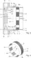
- the spacer element 8 as in the embodiment shown, includes a spacer sleeve 20, which in the securing position S S is arranged coaxially on the sleeve section 2 of the box housing body 1 in an axial area behind the extension sleeve 6, as can be seen in particular from Fig. 3 can be seen, the shape of the spacer sleeve 20 being particularly evident from the Fig. 2 and 7 is evident.
- the spacer sleeve 20 is designed as a circumferentially open, contractible annular sleeve 21 and has a user-operable closing actuation structure 22. Due to its circumferentially open design, the annular sleeve 21 has two circumferential end regions 21a, 21b spaced apart from one another in the circumferential direction, as shown in Fig. 7 marked.
- the spacer sleeve 20 can be gripped by the user at the closing actuation structure 22 and contracted to a certain extent determined by the circumferential distance between the two circumferential end regions 21a, 21b, i.e., narrowed in its radial extent. This facilitates the insertion of the spacer sleeve 20 into the interior of the sleeve section 2 of the box housing body 1 and, in the same way, the removal of the spacer sleeve 20 from the sleeve section 2.
- the spacer sleeve 20 has a radially inwardly projecting flange structure 23 on a front end 20a, i.e. in the mounted position pointing opposite to the push-back direction Z R of the extension sleeve 6.
- This flange structure can serve as a contact surface against which the extension sleeve 6 comes to rest when the spacer sleeve 20 is in its mounted position in the sleeve section 2 of the box housing body 1 and the extension sleeve 6 is positioned on the sleeve section 2 and pushed back to its mounting position M S.
- the front edge of the front end 20a of the spacer sleeve 20 functions as such a stop for positioning the extension sleeve 6 in its mounting position M S .
- the flange structure 23 can function as the closing actuation structure 22.
- the flange structure 23 in the example shown includes two flange arms 23a, 23b, each on one of the two circumferential end regions 21a, 21b, which the annular sleeve 21 has due to its circumferentially open shape.
- the user can then easily remove the spacer sleeve 20, which has been radially narrowed in this way, from the sleeve section 2 of the box housing body 1. In a similar way, the user can easily insert the spacer sleeve 20 into the sleeve section 2.
Landscapes
- Engineering & Computer Science (AREA)
- Public Health (AREA)
- Water Supply & Treatment (AREA)
- Health & Medical Sciences (AREA)
- Life Sciences & Earth Sciences (AREA)
- Hydrology & Water Resources (AREA)
- Architecture (AREA)
- General Engineering & Computer Science (AREA)
- Structural Engineering (AREA)
- Civil Engineering (AREA)
- Mechanical Engineering (AREA)
- Connection Or Junction Boxes (AREA)
- Quick-Acting Or Multi-Walled Pipe Joints (AREA)
Claims (12)
- Unité de boîte de raccordement pour montage encastré avec- un corps de boîtier de boîte (1) avec une section de base (2) côté arrière et une section de manchon (3) dépassant de la section de base, vers l'avant, laquelle section de manchon entoure du côté circonférentiel un espace de logement (4) de composants encastrés, accessible via une extrémité frontale (5) avant, ouverte de la section de manchon,- un manchon de rallonge (6) qui est conçu pour la disposition coaxiale sur la section de manchon et le repoussement axial par rapport à la section de manchon, et- une structure de maintien (7) qui permet un repoussement axial du manchon de rallonge sur la section de manchon, d'une position de montage (MS) jusque dans une position d'utilisation finale (ES) à une hauteur axiale variable (HE) et maintient le manchon de rallonge sur la section de manchon dans la position d'utilisation finale,- sachant que la structure de maintien (7) comprend une structure à bourrelet de maintien (7a), saillant radialement sur la section de manchon (3) et une structure de contre-maintien (7b) formée sur le manchon de rallonge, interagissant avec la structure à bourrelet de maintien par frottement et/ou complémentarité de forme,
caractérisée en ce que- la structure à bourrelet de maintien est constituée d'un matériau déformable de manière étanchéifiante, d'un seul tenant avec au moins une zone partielle (3a) axiale adjacente de la section de manchon (3) dans le matériau déformable de manière étanchéifiante et que la structure de contre-maintien (7b) est constituée d'un matériau plus rigide que le matériau déformable de manière étanchéifiante. - Unité de boîte de raccordement pour montage encastré selon la revendication 1, caractérisée également en ce que l'unité de boîte de raccordement pour montage encastré comprend un élément d'espacement (8) qui est installable de manière amovible sur le corps de boîtier de boîte (1), dans une position de blocage dans laquelle l'élément d'espacement bloque le manchon de rallonge dans la position de montage (MS) pour empêcher un repoussement axial.
- Unité de boîte de raccordement pour montage encastré selon la revendication 1 ou 2, caractérisée également en ce que la structure à bourrelet de maintien comprend un bourrelet de maintien (9) s'étendant de manière continue autour du côté circonférentiel, laquelle structure est saillante radialement vers l'intérieur, sur un côté intérieur (3b) de la section de manchon ou radialement vers l'extérieur, sur un côté extérieur (3c) de la section de manchon.
- Unité de boîte de raccordement pour montage encastré selon la revendication 1 à 3, caractérisée également en ce que la structure à bourrelet de maintien est constituée d'un matériau en mousse synthétique, notamment d'un matériau en mousse particulaire thermoplastique.
- Unité de boîte de raccordement pour montage encastré selon la revendication 1 à 4, caractérisée également en ce que la structure de contre-maintien contient une structure dentée de maintien (10) avec une pluralité de dents de maintien (11) se succédant axialement, qui, s'étendant du côté circonférentiel, sont saillantes radialement vers l'extérieur, sur un côté extérieur (6a) du manchon de rallonge ou radialement vers l'intérieur, sur un côté intérieur (6b) du manchon de rallonge.
- Unité de boîte de raccordement pour montage encastré selon la revendication 5, caractérisée également en ce que la structure dentée de maintien présente, au niveau de ses dents de maintien, un profil en dents de scie avec des flancs arrière de dents (11a) plus plats, pointant dans le sens de repoussement (ZR) du manchon de rallonge et des flancs avant de dents (11b) opposés, plus obliques.
- Unité de boîte de raccordement pour montage encastré selon la revendication 5 ou 6, caractérisée également en ce que la structure dentée de maintien est disposée avec un écart axial par rapport à une extrémité frontale (6c) côté arrière du manchon de rallonge et qu'une section du manchon de rallonge, s'étendant axialement de l'extrémité frontale côté arrière à la structure dentée de maintien au maximum, forme une zone d'emboîtement de prémontage (12) qui est conçue sur la section de manchon du corps de boîtier de boîte, pour le maintien emboîté prémonté du manchon de rallonge dans sa position de montage.
- Unité de boîte de raccordement pour montage encastré selon l'une des revendications 1 à 7, caractérisée également en ce que le manchon de rallonge présente, sur une extrémité frontale (6d) avant, une collerette terminale (13) saillant radialement vers l'extérieur.
- Unité de boîte de raccordement pour montage encastré selon l'une des revendications 1 à 8, caractérisée également en ce qu'un couvercle de montage (17) est installable de manière amovible, sur une extrémité frontale (6d) avant du manchon de rallonge.
- Unité de boîte de raccordement pour montage encastré selon l'une des revendications 2 à 9, caractérisée également en ce que l'élément d'espacement comprend un manchon d'espacement (20) qui, dans la position de blocage, est disposé coaxialement sur la section de manchon dans une zone axiale derrière le manchon de rallonge.
- Unité de boîte de raccordement pour montage encastré selon la revendication 10, caractérisée également en ce que le manchon d'espacement est conçu sous la forme d'un manchon annulaire (21) contractable, ouvert du côté circonférentiel et présente une structure d'actionnement de fermeture (22) actionnable par l'utilisateur.
- Unité de boîte de raccordement pour montage encastré selon la revendication 10 ou 11, caractérisée également en ce que le manchon d'espacement présente, sur une extrémité frontale (20a) avant, une structure de bride (23) faisant saillie radialement vers l'intérieur.
Applications Claiming Priority (1)
| Application Number | Priority Date | Filing Date | Title |
|---|---|---|---|
| DE102020203797.3A DE102020203797A1 (de) | 2020-03-24 | 2020-03-24 | Wandeinbau-Anschlussboxeinheit mit Verlängerungshülse |
Publications (3)
| Publication Number | Publication Date |
|---|---|
| EP3885497A1 EP3885497A1 (fr) | 2021-09-29 |
| EP3885497B1 true EP3885497B1 (fr) | 2025-06-04 |
| EP3885497C0 EP3885497C0 (fr) | 2025-06-04 |
Family
ID=75203007
Family Applications (1)
| Application Number | Title | Priority Date | Filing Date |
|---|---|---|---|
| EP21164305.1A Active EP3885497B1 (fr) | 2020-03-24 | 2021-03-23 | Unité de boîtier de raccordement destinée à être encastrée pourvu de manchon d'extension |
Country Status (10)
| Country | Link |
|---|---|
| US (1) | US11811204B2 (fr) |
| EP (1) | EP3885497B1 (fr) |
| CN (1) | CN113445582B (fr) |
| DE (1) | DE102020203797A1 (fr) |
| ES (1) | ES3040092T3 (fr) |
| PL (1) | PL3885497T3 (fr) |
| RU (1) | RU2770833C1 (fr) |
| SA (1) | SA121420596B1 (fr) |
| SG (1) | SG10202102991VA (fr) |
| ZA (1) | ZA202101865B (fr) |
Families Citing this family (4)
| Publication number | Priority date | Publication date | Assignee | Title |
|---|---|---|---|---|
| DE102020203792A1 (de) | 2020-03-24 | 2021-09-30 | Hansgrohe Se | Wandeinbau-Anschlussboxeinheit |
| DE102020203800A1 (de) * | 2020-03-24 | 2021-09-30 | Hansgrohe Se | Sanitäre Wandeinbau-Anschlussboxeinheit mit elektrischer Leitungsdurchführung |
| DE102020203794A1 (de) | 2020-03-24 | 2021-09-30 | Hansgrohe Se | Wandeinbau-Anschlussboxeinheit mit Funktionsflächenkörper |
| DE102023112622A1 (de) * | 2023-05-12 | 2024-11-14 | Grohe Ag | Anschlusskörper für einen Unterputzeinbaukörper und Unterputzeinbaukörper für eine Sanitärarmatur |
Family Cites Families (84)
| Publication number | Priority date | Publication date | Assignee | Title |
|---|---|---|---|---|
| US1822056A (en) | 1929-02-07 | 1931-09-08 | Gillette Vibber Company Inc | Threadless pipe connecter |
| US2297862A (en) * | 1939-08-30 | 1942-10-06 | Walter H Bachmann | Switch box |
| GB622374A (en) | 1946-03-16 | 1949-05-02 | Du Pont | Improvements in and relating to the photo-polymerisation of compounds containing theethylene double bond |
| DE2637719C3 (de) | 1976-08-21 | 1979-02-22 | Hansa Metallwerke Ag, 7000 Stuttgart | Unterputz-Armatur |
| US4265365A (en) | 1978-04-28 | 1981-05-05 | Slater Electric Inc. | Moisture resistant electrical outlet box |
| US4181329A (en) | 1979-02-02 | 1980-01-01 | Gordon H. Cork | Releasable tube coupling |
| US4265265A (en) | 1979-09-10 | 1981-05-05 | Chicago Pneumatic Tool Company | Pneumatic tool governor |
| DE3310138C2 (de) | 1983-03-21 | 1986-07-24 | Thyssen Plastik Anger KG, 8000 München | Installationsdoseneinheit |
| DE3907588A1 (de) | 1989-03-09 | 1990-09-13 | Grohe Armaturen Friedrich | Befestigungsvorrichtung |
| ATA242889A (de) | 1989-10-23 | 1995-06-15 | Geberit Ag | Geschäumter installationsbaustein für sanitäreinrichtungen |
| CH681237A5 (fr) | 1990-07-26 | 1993-02-15 | Nussbaum & Co Ag R | |
| DE9115323U1 (de) | 1991-12-11 | 1993-04-08 | Grote & Hartmann Gmbh & Co Kg, 5600 Wuppertal | Dichtungsstopfen für elektrische Leitungen |
| DE4241989A1 (de) | 1992-12-12 | 1994-06-16 | Grohe Armaturen Friedrich | Unterputz-Armatur |
| DE4417485C2 (de) | 1994-05-19 | 1997-08-28 | Hansa Metallwerke Ag | Sanitärarmatur |
| US5783774A (en) * | 1996-10-21 | 1998-07-21 | Walker Systems, Inc. | Non-metallic floor box |
| DE19648587B4 (de) | 1996-11-23 | 2004-04-15 | Hansa Metallwerke Ag | Unterputz-Einbaukasten für Sanitärarmaturen |
| DE19715651B4 (de) | 1997-04-15 | 2005-09-29 | Ortwein Sanitär Original Heizung GmbH | Vorrichtung zum schall- und wärmedämmenden Anschluß von Sanitärarmaturen etc. |
| US5913439A (en) * | 1997-08-29 | 1999-06-22 | Watlow Electric Manufacturing Co. | Mounting assembly with dual mount collar |
| GB2337287A (en) * | 1998-05-13 | 1999-11-17 | Barber Eduard & Co Ltd | Boundary box |
| DE19856156A1 (de) | 1998-12-05 | 2000-06-08 | Grohe Kg Hans | Befestigungsanordnung für sanitäre Bauteile |
| DE10036996A1 (de) | 2000-07-06 | 2002-01-17 | Illbruck Gmbh | Wannenträger-Anbauelement |
| US6499771B1 (en) | 2000-07-18 | 2002-12-31 | Victaulic Company Of America | Mechanical pipe coupling with toothed retainer |
| DE20105345U1 (de) | 2001-03-26 | 2001-07-12 | Eisenwerk Wittigsthal GmbH, 08349 Johanngeorgenstadt | Montageeinheit für die Sanitär- und Heizungsinstallation |
| DE10122022A1 (de) | 2001-05-07 | 2002-11-14 | Grohe Armaturen Friedrich | Unterputzwasserarmatur |
| JP4398115B2 (ja) | 2001-06-13 | 2010-01-13 | 未来工業株式会社 | 管引出具 |
| AU2003214029A1 (en) * | 2002-03-27 | 2003-10-08 | Daxtor Aps | Expansion unit |
| EP1355399B8 (fr) * | 2002-04-19 | 2010-03-03 | C & C MARSHALL LIMITED | Accessoire de montage |
| DE20321431U1 (de) | 2002-07-18 | 2007-04-05 | Hansgrohe Ag | Installationseinrichtung für Sanitärelement |
| DE10233858A1 (de) | 2002-07-18 | 2004-01-29 | Hansgrohe Ag | Installationseinrichtung für Sanitärelemente |
| US20050194785A1 (en) | 2003-10-03 | 2005-09-08 | Sami Shemtov | Rain tight compression fitting coupling device |
| DE102004060744A1 (de) | 2004-12-15 | 2006-06-22 | Kludi Gmbh & Co. Kg | Unterputz-Gehäuse für eine Wasseranschlusseinheit |
| US6992252B1 (en) | 2005-03-29 | 2006-01-31 | Sigma Electric Manufacturing Corp. | Reducer bushing for weatherproof outlet boxes |
| FI118447B (fi) * | 2005-11-17 | 2007-11-15 | Ensto Busch Jaeger Oy | Koje- tai jakorasia |
| DE102007002235A1 (de) | 2007-01-10 | 2008-07-17 | Markus Morent | Vorrichtung zur Installation einer Sanitär- und/oder Elektrokomponente an einem Tragelement |
| US8480134B2 (en) | 2007-05-25 | 2013-07-09 | Quick Fitting, Inc. | Piping joint assembly system and method with sealing ring stabilizer |
| US7462775B1 (en) | 2007-06-25 | 2008-12-09 | Arlington Industries, Inc. | Adjustable electrical box for flush or offset mounting of electrical devices on brick or stone walls |
| DE102007044284A1 (de) | 2007-09-07 | 2009-03-12 | Hansgrohe Ag | Anschlussanordnung |
| US8474877B2 (en) | 2007-09-19 | 2013-07-02 | Bridgeport Fittings, Inc. | Push-in fitting for electrical metallic tubing with enhanced sealing and continuity |
| DE102008013736B4 (de) | 2008-03-11 | 2017-07-06 | Ideal Standard International Nv | Einbaukasten zum variablen Einbau von Sanitärarmaturen |
| DE102008027382A1 (de) | 2008-06-09 | 2009-12-17 | Uponor Innovation Ab | Pressfitting für ein Rohr, insbesondere Kunststoffrohr oder Kunststoff-Metall-Verbundrohr |
| AT507052B1 (de) | 2008-06-17 | 2010-07-15 | Baumgartner Johannes | Wandeinbaublock für installationen |
| US8899431B1 (en) * | 2008-09-12 | 2014-12-02 | Hubbell Incorporated | Extendable electrical box |
| US8158884B2 (en) | 2008-11-17 | 2012-04-17 | Thomas & Betts International, Inc. | Angled slots for installation of outdoor metallic boxes |
| DE102008064253B3 (de) | 2008-12-20 | 2010-02-11 | Ideal Standard International Bvba | Unterputzkasten für die Montage von Sanitärbauteilen |
| AT507426B1 (de) | 2008-12-23 | 2010-05-15 | Alois Mochart | Montageblock für den anschluss von geräten |
| DE102009012838B3 (de) | 2009-03-04 | 2010-08-19 | Hansgrohe Ag | Gehäuse für eine Armatur |
| DE102009012840B3 (de) | 2009-03-04 | 2010-08-19 | Hansgrohe Ag | Anschlussblock für Sanitärarmaturen |
| DE102009049711A1 (de) | 2009-10-17 | 2011-04-21 | Abb Ag | Elektro-Installationsgerät mit Trägerrahmen und Wandausgleichselementen |
| DE212010000212U1 (de) | 2010-03-29 | 2013-04-22 | Robert Bosch Limitada | Dichte elektrische Verbinderanordnung |
| DE102010055805A1 (de) | 2010-12-23 | 2012-06-28 | Ideal-Standard International Bvba | Unterputz-Einbaukasten für ein eine elektronisch ansteuerbare Temperatur- und Volumensteuereinheit aufwesendes Mischmodul |
| US8398122B2 (en) | 2010-12-30 | 2013-03-19 | Quick Fitting, Inc. | Push connect joint assembly, system and method |
| US9725892B2 (en) | 2011-04-28 | 2017-08-08 | Sioux Chief Mfg. Co., Inc. | Plumbing supply line mounting and finish panel assembly |
| US9086179B1 (en) | 2011-06-16 | 2015-07-21 | Naris Komolrochanaporn | Quick coupling pipe fitting system |
| DE102012203393A1 (de) | 2012-03-05 | 2013-09-05 | Hansgrohe Se | Höheneinstellbarer Putzdickenausgleich eines iBox Grundsets |
| DE102012011599C5 (de) * | 2012-06-13 | 2023-11-16 | Rose Plastic Ag | Polygonartige Schiebeverpackung mit Dreh-Schub-Bewegung zum Öffnen und Verschließen |
| DK2822121T3 (en) | 2013-07-05 | 2018-06-14 | Schneider Electric Danmark As | Extension assembly for an electrical wiring box |
| WO2015096811A1 (fr) | 2013-12-27 | 2015-07-02 | 厦门松霖科技有限公司 | Ensemble préintégré encastré |
| DE202014106179U1 (de) * | 2014-01-09 | 2015-03-23 | Wolfgang Hofmann | Höhenverstellbare Straßenkappe |
| DE102014208291B4 (de) | 2014-05-02 | 2018-02-15 | Icotek Project Gmbh & Co. Kg | Vorrichtung zum Hindurchführen und Einspannen von Kabeln |
| DE102014107655B4 (de) | 2014-05-30 | 2024-07-11 | Voss Automotive Gmbh | Steckverbinder für Fluidleitungen mit innenliegender Adapterhülse |
| DE202015001883U1 (de) | 2015-03-09 | 2016-06-10 | Neoperl Gmbh | Sanitäres Einsetzelement |
| PL3271518T3 (pl) | 2015-03-16 | 2020-11-16 | Fir Italia S.P.A. | Uniwersalny osadzony system do części składowych baterii sanitarnej |
| US9667053B2 (en) * | 2015-06-01 | 2017-05-30 | Hubbell Incorporated | Adjustable floor box |
| CN204732809U (zh) * | 2015-06-09 | 2015-10-28 | 张少伟 | 一种电器接线盒 |
| DE102015112420A1 (de) | 2015-07-29 | 2017-02-02 | Kaiser Gmbh & Co. Kg | Installationsdose |
| AT517356B1 (de) | 2015-12-04 | 2017-01-15 | Wogro Gmbh | Installationsdose für wenigstens einen Leitungsanschluss |
| RU169542U1 (ru) * | 2016-04-19 | 2017-03-22 | Общество с ограниченной ответственностью "Консальт-Плюс" | Электромонтажная коробка (подрозетник) |
| ES2952103T3 (es) | 2016-04-21 | 2023-10-27 | Jarola Vision B V | Sistema de construcción modular, elemento de acoplamiento, objeto, herramienta y embalaje |
| US10280598B2 (en) | 2016-05-16 | 2019-05-07 | Dahata Inc. | Faucet assembly |
| US10006577B2 (en) | 2016-07-15 | 2018-06-26 | Miniature Precision Components, Inc. | Permanent quick connector and assembly therewith |
| US10186852B2 (en) * | 2016-10-28 | 2019-01-22 | Allied Moulded Products, Inc. | Seal for electrical box |
| DE102017100710A1 (de) | 2017-01-16 | 2018-07-19 | Grohe Ag | Unterputzeinbaukörper für eine Sanitärarmatur mit einem zweiteiligen Gehäuse |
| DE102017100707A1 (de) | 2017-01-16 | 2018-07-19 | Grohe Ag | Unterputzbox für einen Armaturenkörper mit einem Befestigungsrahmen |
| ES2930049T3 (es) | 2017-03-23 | 2022-12-05 | Fischer Georg Jrg Ag | Conector de conexión |
| US10865922B2 (en) | 2017-10-05 | 2020-12-15 | Novares Us Engine Components, Inc. | Anti-tamper permanent quick connect coupling device |
| DE102017127151A1 (de) | 2017-11-17 | 2019-05-23 | Grohe Ag | Unterputzeinbaukörper für eine Sanitärarmatur mit einer Kabeldurchführung |
| US11209083B2 (en) * | 2018-01-18 | 2021-12-28 | Specified Technologies Inc. | Self-sealing membrane sleeve assembly |
| FI3570396T3 (fi) | 2018-05-14 | 2023-04-25 | Schneider Electric Ind Sas | Säädettävä rengaskokoonpano sähköasennusrasiaa varten |
| CN208461082U (zh) | 2018-07-23 | 2019-02-01 | 佳能企业股份有限公司 | 电子系统、出线口结构及缆线 |
| CN209388954U (zh) | 2019-03-11 | 2019-09-13 | 南京铁道职业技术学院 | 一种继电器保护罩 |
| DE102020203794A1 (de) | 2020-03-24 | 2021-09-30 | Hansgrohe Se | Wandeinbau-Anschlussboxeinheit mit Funktionsflächenkörper |
| DE102020203792A1 (de) | 2020-03-24 | 2021-09-30 | Hansgrohe Se | Wandeinbau-Anschlussboxeinheit |
| DE102020203800A1 (de) | 2020-03-24 | 2021-09-30 | Hansgrohe Se | Sanitäre Wandeinbau-Anschlussboxeinheit mit elektrischer Leitungsdurchführung |
| EP4002617A1 (fr) * | 2020-11-13 | 2022-05-25 | Eaton Intelligent Power Limited | Ensemble bague à profondeur réglable et procédé d'installation |
-
2020
- 2020-03-24 DE DE102020203797.3A patent/DE102020203797A1/de active Pending
-
2021
- 2021-03-18 RU RU2021107170A patent/RU2770833C1/ru active
- 2021-03-19 ZA ZA2021/01865A patent/ZA202101865B/en unknown
- 2021-03-23 ES ES21164305T patent/ES3040092T3/es active Active
- 2021-03-23 EP EP21164305.1A patent/EP3885497B1/fr active Active
- 2021-03-23 PL PL21164305.1T patent/PL3885497T3/pl unknown
- 2021-03-23 SG SG10202102991V patent/SG10202102991VA/en unknown
- 2021-03-23 US US17/209,899 patent/US11811204B2/en active Active
- 2021-03-24 SA SA121420596A patent/SA121420596B1/ar unknown
- 2021-03-24 CN CN202110312452.3A patent/CN113445582B/zh active Active
Also Published As
| Publication number | Publication date |
|---|---|
| ZA202101865B (en) | 2022-07-27 |
| EP3885497A1 (fr) | 2021-09-29 |
| SG10202102991VA (en) | 2021-10-28 |
| CN113445582B (zh) | 2023-04-07 |
| EP3885497C0 (fr) | 2025-06-04 |
| PL3885497T3 (pl) | 2025-10-13 |
| US20210305793A1 (en) | 2021-09-30 |
| ES3040092T3 (en) | 2025-10-28 |
| CN113445582A (zh) | 2021-09-28 |
| RU2770833C1 (ru) | 2022-04-22 |
| DE102020203797A1 (de) | 2021-09-30 |
| US11811204B2 (en) | 2023-11-07 |
| SA121420596B1 (ar) | 2023-02-15 |
Similar Documents
| Publication | Publication Date | Title |
|---|---|---|
| EP3885497B1 (fr) | Unité de boîtier de raccordement destinée à être encastrée pourvu de manchon d'extension | |
| EP0943856B1 (fr) | Dispositif de raccordement avec saillie de montage | |
| EP1845208B1 (fr) | Dispositif d'installation pour éléments sanitaires | |
| EP2101002B1 (fr) | Boîtier d'encastrement destiné à l'encastrement variable d'armatures sanitaires | |
| EP4254695B1 (fr) | Unité de boîtier de raccordement destinée à être encastrée pourvu de corps de surface fonctionnel | |
| WO2010069606A1 (fr) | Boîtier encastré pour le montage d’éléments sanitaires | |
| DE19828059A1 (de) | Anschlußarmatur mit einem durch Schlitze in Haltezungen aufgeteilten Befestigungsvorsprung | |
| DE29911362U1 (de) | Anschlußarmatur zum Befestigen von länglichen Körpern | |
| DE3815168A1 (de) | Steckkupplung zum ankuppeln eines schlauches an ein rohr | |
| EP3885496A1 (fr) | Unité de boîtier de raccordement destinée à être encastrée | |
| EP1352193B1 (fr) | Dispositif de raccordement enfichable encliquetable | |
| DE102015219175B4 (de) | Anschlussrohrstutzen für eine Sanitärarmatur | |
| EP3117046B1 (fr) | Support intermédiaire | |
| DE102014216975B4 (de) | Sanitärbrause | |
| EP1870526A1 (fr) | Robinet sanitaire | |
| DE19853950B4 (de) | Abdeck-Rosette | |
| DE102010008926B4 (de) | Anschlussvorrichtung für eine Fluidleitung | |
| DE69108853T2 (de) | Vorrichtung zur Schlauchentwässerung eines ausziehbaren Brause-anschlusses. | |
| EP3647513B1 (fr) | Fixation tubulaire | |
| DE202023002746U1 (de) | Schraubverbindung und Funktionsblock für Installationsanschluss | |
| DE10303169A1 (de) | Wandstange mit Gleitstück | |
| DE19623034A1 (de) | Ablaufarmatur mit Teleskopverstellrohr | |
| EP0961070A2 (fr) | Raccord rapide | |
| DE19823320C2 (de) | Anschlußhülse für elektrische Leitungen aufnehmende Leerrohre an Elektroinstallationsgehäusen | |
| DE102023105107A1 (de) | Abdeckrosette und Einbauset für Installationsanschluss |
Legal Events
| Date | Code | Title | Description |
|---|---|---|---|
| PUAI | Public reference made under article 153(3) epc to a published international application that has entered the european phase |
Free format text: ORIGINAL CODE: 0009012 |
|
| STAA | Information on the status of an ep patent application or granted ep patent |
Free format text: STATUS: THE APPLICATION HAS BEEN PUBLISHED |
|
| AK | Designated contracting states |
Kind code of ref document: A1 Designated state(s): AL AT BE BG CH CY CZ DE DK EE ES FI FR GB GR HR HU IE IS IT LI LT LU LV MC MK MT NL NO PL PT RO RS SE SI SK SM TR |
|
| STAA | Information on the status of an ep patent application or granted ep patent |
Free format text: STATUS: REQUEST FOR EXAMINATION WAS MADE |
|
| 17P | Request for examination filed |
Effective date: 20220325 |
|
| RBV | Designated contracting states (corrected) |
Designated state(s): AL AT BE BG CH CY CZ DE DK EE ES FI FR GB GR HR HU IE IS IT LI LT LU LV MC MK MT NL NO PL PT RO RS SE SI SK SM TR |
|
| STAA | Information on the status of an ep patent application or granted ep patent |
Free format text: STATUS: EXAMINATION IS IN PROGRESS |
|
| 17Q | First examination report despatched |
Effective date: 20230816 |
|
| P01 | Opt-out of the competence of the unified patent court (upc) registered |
Effective date: 20230911 |
|
| GRAP | Despatch of communication of intention to grant a patent |
Free format text: ORIGINAL CODE: EPIDOSNIGR1 |
|
| STAA | Information on the status of an ep patent application or granted ep patent |
Free format text: STATUS: GRANT OF PATENT IS INTENDED |
|
| INTG | Intention to grant announced |
Effective date: 20250120 |
|
| GRAS | Grant fee paid |
Free format text: ORIGINAL CODE: EPIDOSNIGR3 |
|
| GRAA | (expected) grant |
Free format text: ORIGINAL CODE: 0009210 |
|
| STAA | Information on the status of an ep patent application or granted ep patent |
Free format text: STATUS: THE PATENT HAS BEEN GRANTED |
|
| AK | Designated contracting states |
Kind code of ref document: B1 Designated state(s): AL AT BE BG CH CY CZ DE DK EE ES FI FR GB GR HR HU IE IS IT LI LT LU LV MC MK MT NL NO PL PT RO RS SE SI SK SM TR |
|
| REG | Reference to a national code |
Ref country code: GB Ref legal event code: FG4D Free format text: NOT ENGLISH |
|
| REG | Reference to a national code |
Ref country code: CH Ref legal event code: EP |
|
| REG | Reference to a national code |
Ref country code: DE Ref legal event code: R096 Ref document number: 502021007619 Country of ref document: DE |
|
| REG | Reference to a national code |
Ref country code: IE Ref legal event code: FG4D Free format text: LANGUAGE OF EP DOCUMENT: GERMAN |
|
| U01 | Request for unitary effect filed |
Effective date: 20250626 |
|
| P04 | Withdrawal of opt-out of the competence of the unified patent court (upc) registered |
Free format text: CASE NUMBER: APP_31467/2025 Effective date: 20250701 |
|
| U07 | Unitary effect registered |
Designated state(s): AT BE BG DE DK EE FI FR IT LT LU LV MT NL PT RO SE SI Effective date: 20250703 |
|
| PG25 | Lapsed in a contracting state [announced via postgrant information from national office to epo] |
Ref country code: GR Free format text: LAPSE BECAUSE OF FAILURE TO SUBMIT A TRANSLATION OF THE DESCRIPTION OR TO PAY THE FEE WITHIN THE PRESCRIBED TIME-LIMIT Effective date: 20250905 Ref country code: NO Free format text: LAPSE BECAUSE OF FAILURE TO SUBMIT A TRANSLATION OF THE DESCRIPTION OR TO PAY THE FEE WITHIN THE PRESCRIBED TIME-LIMIT Effective date: 20250904 |
|
| PG25 | Lapsed in a contracting state [announced via postgrant information from national office to epo] |
Ref country code: HR Free format text: LAPSE BECAUSE OF FAILURE TO SUBMIT A TRANSLATION OF THE DESCRIPTION OR TO PAY THE FEE WITHIN THE PRESCRIBED TIME-LIMIT Effective date: 20250604 |
|
| PG25 | Lapsed in a contracting state [announced via postgrant information from national office to epo] |
Ref country code: RS Free format text: LAPSE BECAUSE OF FAILURE TO SUBMIT A TRANSLATION OF THE DESCRIPTION OR TO PAY THE FEE WITHIN THE PRESCRIBED TIME-LIMIT Effective date: 20250904 |
|
| REG | Reference to a national code |
Ref country code: ES Ref legal event code: FG2A Ref document number: 3040092 Country of ref document: ES Kind code of ref document: T3 Effective date: 20251028 |
|
| PG25 | Lapsed in a contracting state [announced via postgrant information from national office to epo] |
Ref country code: IS Free format text: LAPSE BECAUSE OF FAILURE TO SUBMIT A TRANSLATION OF THE DESCRIPTION OR TO PAY THE FEE WITHIN THE PRESCRIBED TIME-LIMIT Effective date: 20251004 |
|
| PG25 | Lapsed in a contracting state [announced via postgrant information from national office to epo] |
Ref country code: SM Free format text: LAPSE BECAUSE OF FAILURE TO SUBMIT A TRANSLATION OF THE DESCRIPTION OR TO PAY THE FEE WITHIN THE PRESCRIBED TIME-LIMIT Effective date: 20250604 |
|
| PG25 | Lapsed in a contracting state [announced via postgrant information from national office to epo] |
Ref country code: SK Free format text: LAPSE BECAUSE OF FAILURE TO SUBMIT A TRANSLATION OF THE DESCRIPTION OR TO PAY THE FEE WITHIN THE PRESCRIBED TIME-LIMIT Effective date: 20250604 |
|
| REG | Reference to a national code |
Ref country code: CH Ref legal event code: U11 Free format text: ST27 STATUS EVENT CODE: U-0-0-U10-U11 (AS PROVIDED BY THE NATIONAL OFFICE) Effective date: 20260401 |
|
| PGFP | Annual fee paid to national office [announced via postgrant information from national office to epo] |
Ref country code: GB Payment date: 20260323 Year of fee payment: 6 |
|
| PLBE | No opposition filed within time limit |
Free format text: ORIGINAL CODE: 0009261 |
|
| STAA | Information on the status of an ep patent application or granted ep patent |
Free format text: STATUS: NO OPPOSITION FILED WITHIN TIME LIMIT |
|
| REG | Reference to a national code |
Ref country code: CH Ref legal event code: L10 Free format text: ST27 STATUS EVENT CODE: U-0-0-L10-L00 (AS PROVIDED BY THE NATIONAL OFFICE) Effective date: 20260416 |
|
| PGFP | Annual fee paid to national office [announced via postgrant information from national office to epo] |
Ref country code: TR Payment date: 20260305 Year of fee payment: 6 |
|
| PGFP | Annual fee paid to national office [announced via postgrant information from national office to epo] |
Ref country code: CZ Payment date: 20260317 Year of fee payment: 6 |
|
| U20 | Renewal fee for the european patent with unitary effect paid |
Year of fee payment: 6 Effective date: 20260323 |