EP3885506A1 - Poutre porteuse pour systèmes de plafond, système de plafond et son procédé de fabrication - Google Patents
Poutre porteuse pour systèmes de plafond, système de plafond et son procédé de fabrication Download PDFInfo
- Publication number
- EP3885506A1 EP3885506A1 EP21159926.1A EP21159926A EP3885506A1 EP 3885506 A1 EP3885506 A1 EP 3885506A1 EP 21159926 A EP21159926 A EP 21159926A EP 3885506 A1 EP3885506 A1 EP 3885506A1
- Authority
- EP
- European Patent Office
- Prior art keywords
- supporting beam
- base plate
- concrete
- webs
- web
- Prior art date
- Legal status (The legal status is an assumption and is not a legal conclusion. Google has not performed a legal analysis and makes no representation as to the accuracy of the status listed.)
- Withdrawn
Links
Images



Classifications
-
- E—FIXED CONSTRUCTIONS
- E04—BUILDING
- E04C—STRUCTURAL ELEMENTS; BUILDING MATERIALS
- E04C3/00—Structural elongated elements designed for load-supporting
- E04C3/02—Joists; Girders, trusses, or trusslike structures, e.g. prefabricated; Lintels; Transoms; Braces
- E04C3/29—Joists; Girders, trusses, or trusslike structures, e.g. prefabricated; Lintels; Transoms; Braces built-up from parts of different material, i.e. composite structures
- E04C3/293—Joists; Girders, trusses, or trusslike structures, e.g. prefabricated; Lintels; Transoms; Braces built-up from parts of different material, i.e. composite structures the materials being steel and concrete
-
- E—FIXED CONSTRUCTIONS
- E04—BUILDING
- E04B—GENERAL BUILDING CONSTRUCTIONS; WALLS, e.g. PARTITIONS; ROOFS; FLOORS; CEILINGS; INSULATION OR OTHER PROTECTION OF BUILDINGS
- E04B5/00—Floors; Floor construction with regard to insulation; Connections specially adapted therefor
- E04B5/16—Load-carrying floor structures wholly or partly cast or similarly formed in situ
- E04B5/17—Floor structures partly formed in situ
- E04B5/23—Floor structures partly formed in situ with stiffening ribs or other beam-like formations wholly or partly prefabricated
- E04B5/29—Floor structures partly formed in situ with stiffening ribs or other beam-like formations wholly or partly prefabricated the prefabricated parts of the beams consisting wholly of metal
-
- E—FIXED CONSTRUCTIONS
- E04—BUILDING
- E04B—GENERAL BUILDING CONSTRUCTIONS; WALLS, e.g. PARTITIONS; ROOFS; FLOORS; CEILINGS; INSULATION OR OTHER PROTECTION OF BUILDINGS
- E04B9/00—Ceilings; Construction of ceilings, e.g. false ceilings; Ceiling construction with regard to insulation
- E04B9/06—Ceilings; Construction of ceilings, e.g. false ceilings; Ceiling construction with regard to insulation characterised by constructional features of the supporting construction, e.g. cross section or material of framework members
-
- E—FIXED CONSTRUCTIONS
- E04—BUILDING
- E04C—STRUCTURAL ELEMENTS; BUILDING MATERIALS
- E04C5/00—Reinforcing elements, e.g. for concrete; Auxiliary elements therefor
- E04C5/01—Reinforcing elements of metal, e.g. with non-structural coatings
- E04C5/06—Reinforcing elements of metal, e.g. with non-structural coatings of high bending resistance, i.e. of essentially three-dimensional [3D] extent, e.g. lattice girders
- E04C5/0604—Prismatic or cylindrical reinforcement cages composed of longitudinal bars and open or closed stirrup rods
- E04C5/0618—Closed cages with spiral- or coil-shaped stirrup rod
Definitions
- the invention relates to a support beam for ceiling systems according to the preamble of claim 1.
- Such support beams are often used in reinforced concrete or composite construction, in particular in the construction of ceiling systems or storey ceilings.
- the EP 1 611 295 B1 a generic support beam.
- This has a hollow box cross-section and serves as a support for plate-shaped semi-finished parts or prefabricated parts. After laying the semi-finished or prefabricated parts, a local or large-area in-situ concrete layer is applied, which also penetrates into the interior of the hollow box cross-section of the supporting beam in order to produce the composite ceiling system.
- these support beams which as such only consist of steel, in-situ concrete is introduced into the space of the support beam, which is defined by the webs, a base plate and an upper plate (top flange) opposite the base plate (bottom flange) when connecting to the ceiling panels on the construction site .
- the supporting beam has a carrier, in particular a steel carrier, which has a base plate and at least one, preferably two, web or webs arranged at an angle to this, in particular perpendicularly.
- the supporting beam is characterized in that a space delimited by the web or the webs and the base plate, preferably each made of steel, is at least partially filled with concrete, which is preferably not in-situ concrete, or the space between the web and the base plate or
- the webs and the base plate are at least partially filled with concrete, which is in particular not in-situ concrete.
- Steel and concrete work together here in a composite construction. Reinforcing steel in the form of stirrups and rods can be inserted into the concrete to absorb forces and to increase the bond effect.
- the supporting beam in composite construction is used according to the invention in a ceiling system in composite construction, the supporting beam being used to support at least one semi-prefabricated part or prefabricated part and an in-situ concrete layer, in particular outside the concrete, which defines the space delimited by the web or the webs and the base plate or the space between the web or the webs and the base plate at least partially fills, is provided at least in the connection area between the at least one support beam and the semi-finished part or prefabricated part.
- a ceiling system in composite construction which has at least one supporting beam according to the invention, at least one semi-finished part or prefabricated part, which is supported on the at least one supporting beam, and an in-situ concrete layer, which at least in the connection area between the at least one supporting beam and the semi-finished part or Prefabricated part is provided, in particular outside the concrete, which at least partially fills the space between the web or the webs and the base plate or the space delimited by the web or the webs and the base plate.
- a method for producing a ceiling system in composite construction namely with the steps of supporting at least one supporting beam according to the invention on supports, supporting at least one semi-finished part or prefabricated part on the at least one supporting beam, providing composite elements in the connection area between the at least one supporting beam and the semi-finished part or prefabricated part, provision of an in-situ concrete layer at least in the connection area between the at least one supporting beam and the semi-finished part or prefabricated part, in particular outside the concrete, which at least partially fills the space between the web or webs and the base plate.
- the supporting beam is produced in and for the composite construction in several production steps.
- reinforcement cages consisting of stirrups and steel bars and then later concrete can be introduced into the supporting beam at a later moment, so that initially a semi-finished part is present that, in addition to the steel girder, has composite means, in particular form-fit means, for creating a form fit with the concrete to be filled .
- the supporting beam already has before the connection with semi-finished parts or Precast concrete.
- the concrete is provided at least in sections in this space before the connection with the prefabricated part or semi-finished part, i.e. before the in-situ concrete layer is provided in the connection area between the supporting beam and the semi-finished part or prefabricated part.
- the support beam as such therefore already has at least some sections of concrete that is not in-situ concrete prior to connection with the prefabricated or semi-finished part in the space delimited by the web or the webs and the base plate or in the space between the web or the webs and the base plate .
- this space is completely filled, apart from the through openings, around possible steel reinforcements, with concrete that is not in-situ concrete.
- the supporting beam according to the invention in composite construction already has concrete during assembly, that is to say before connection to the ceiling system by in-situ concrete, it can withstand the load of the ceiling or of the prefabricated part or semi-finished part reliably during assembly, over its entire length without the need to use intermediate or auxiliary supports.
- a pressure zone is already present in the delivery state; No additional support is then required even for laying ceiling elements, since the pressure zone is already (preferably completely) formed by the concrete with or without reinforcement.
- the construction height of the supporting beam corresponds to the height of the ceiling system plus the thickness of the base plate. In this way, the construction height of the ceiling system can be minimized, which leads to a reduction in the construction volume without having to reduce the usable area at the same time.
- the arrangement of steel and concrete in the supporting beam can be optimized with regard to the requirements for compressive strength. This is because the space or the space between the web or the webs and the base plate bounded by the web or the webs and the base plate is at least partially filled with concrete, which is preferably not in-situ concrete, the pressure zone of the beam for the Traffic load case is.
- the use of concrete instead of a steel belt reduces the weight of the support beam.
- the invention is based on the idea of using a supporting beam in ceiling systems, the supporting beam as Composite component itself already has concrete before it is connected to the ceiling system.
- the supporting beam as a prefabricated composite part as such has not only steel but also concrete, it can also be viewed as a "hybrid beam".
- a so-called steel-concrete composite beam or “composite beam”
- the tensile stress is taken over by the steel component and the compressive stress is largely taken over by the concrete component. Strong forces can be absorbed by inserted pressure reinforcement.
- the base plate is to be understood in particular as the lower chord.
- the base plate and the web arranged at an angle thereto or the webs arranged angled thereto and protruding from the same side of the base plate define the space in which the concrete is provided at least in sections.
- the arrangement of the base plate and the webs is preferably U-shaped in cross section perpendicular to the longitudinal direction of the support beam.
- One possible shape also provides a web in the middle with the base plate below in a concrete beam.
- the space for creating the concrete beam is then defined by auxiliary formwork on both sides. It is also possible to implement more than two webs, for example a central web and two lateral webs, to delimit space at the side.
- the base plate can be laterally stiffened by transverse rib webs and thus receive more load-bearing capacity. These rib webs are then to be coordinated with the ceiling elements to be placed by means of cutouts or boundaries, dimensions, so that they can nevertheless rest on the base plate.
- the concrete is any concrete, preferably a high-strength concrete, for example SCC.
- a class C 60/75 concrete can with chemical Plasticizers can be used as additives or mixed carbon fibers or glass fibers.
- the concrete is preferably high-strength concrete (cylinder strength between 50 N / mm 2 and 100 N / mm 2 (C 100/115)).
- the concrete can be reinforced concrete (preferably reinforced concrete reinforced with reinforcing steel stirrups and bars). The concrete filling can therefore be carried out with or without reinforcement.
- additional bonding agents are arranged. These can be formed by shaping the steel parts and / or by additionally applied composite bodies such as head bolts, perforated sheet metal strips and / or structured parts that transfer forces between concrete and steel.
- the space filled with the concrete at least in sections is open at least in some areas, preferably completely, on the side facing away from the base plate.
- the carrier is preferably free of an upper steel plate running parallel to the base plate, i.e. an upper belt made of steel, which delimits the space between the webs and the base plate, so that the space without an opposing plate is referred to as open.
- the steel belt can therefore be dispensed with.
- This embodiment has the advantage over the use of an additional upper plate, that is to say a steel belt, that the weight of the supporting beam is reduced by using less steel.
- the use of concrete in this pressure range is advantageous because steel is less pressure-resistant than concrete.
- the space to be filled with concrete is at least partially, preferably completely, open on the side facing away from the base plate, the concrete can be filled more easily, namely directly from above instead of laterally through the webs. This means that no bubbles form in the concrete, which makes the manufacture of such a supporting beam further easier and more reliable.
- the concrete protrudes over at least one web by an overhang, the overhang preferably extending in a direction perpendicular to the base plate.
- the overhang is preferably dimensioned in such a way that the overhang is flush with the ceiling plate. Then it is not necessary to provide concrete.
- the overhang can be a reinforced concrete body.
- the protrusion preferably has a toothing, in particular a longitudinal groove. These teeth can absorb the horizontal transverse forces.
- the toothing also serves to create an overall load-bearing effect between the supporting beam and the ceiling elements placed on it as a rigid ceiling pane. In special cases, it is possible to apply additional in-situ concrete layers to achieve higher ceiling rigidity.
- One embodiment can have a hanger basket.
- Reinforcing steel preferably in the form of longitudinal bars, be arranged.
- the bracket cage and the reinforcing steel can be surrounded by concrete at least in sections, preferably completely. This arrangement of reinforcement in cooperation with the surrounding concrete then represents reinforced concrete which at least partially fills the space delimited by the web or the webs and the base plate.
- the connecting means can extend through intermediate spaces in the bracket basket in the direction transverse to the longitudinal direction L, that is to say in the transverse direction. This can strengthen the composite effect.
- the inner surfaces of the web or webs i.e. the surfaces that define the space between the webs on the inside, and / or the base plate, i.e. the side of the base plate that defines the space between the webs and the base plate on the inside, have bonding agents.
- This can also mean that the web or the webs and / or the base plate itself are designed in such a way that they act as a connecting means.
- Composite means can also be arranged integrally or additionally on the inner surface of the web or webs and / or the base plate. Bonding agents improve the bond between the beam and the concrete.
- the composite means also preferably has form-fitting means, in particular headed bolts. These can in particular extend at an angle from the webs into the space, further preferably essentially parallel to the base plate and perpendicular to the webs arranged perpendicular to the base plate.
- composite bolts can also be provided from the base plate, preferably running parallel to the webs, and / or several composite bolts, which extend from a web, preferably perpendicular to the base plate and are variable with regard to their distance from the base plate, preferably displaceable along the web.
- composite means for forming a form fit can be implemented as desired, as long as they, and thus the webs and / or the base plate, are designed to absorb and transmit composite transverse forces. They can, for example, be depressions and / or projections that enable a toothing between the webs or the base plate and the concrete.
- a wave-like shape is conceivable on the inside of the webs or base plate, for example in that correspondingly wave-shaped sheets or sheet metal strips with a force-introducing effect as a composite material that are perforated, twisted or otherwise structured in the longitudinal direction are arranged on the inside and welded to the webs or the base plate .
- Another option is a bar with cutouts.
- the individual elements of the supporting beam themselves by appropriate shaping, for example such as corrugation, folds, indentations or other shapes, in interaction with the concrete, transmit forces especially in the longitudinal direction between concrete and steel parts.
- the supporting beam can also be higher than the ceiling elements placed on top.
- the webs are designed to be corrugated or folded on the upper side by an upstream local shaping process. This not only helps to transfer the bond forces between concrete and steel, but it also makes it possible to bend or arch the side bars before welding them to the base plate in order to create a curved supporting beam. Ease of manufacture is therefore of economic and technical importance.
- the supporting beam can preferably have an elevation which preferably corresponds to a later deflection.
- These supporting beams which are produced with so-called canting, have advantages for the perceptible small deflection in the finished structure, because the deflection when the ceiling elements are applied and the canting are more or less canceled out. In any case, whether with deformed upper web elements or flat web elements, this is easier to produce with a supporting beam without a steel belt than with an upper belt, because fewer parts have to be held and welded.
- An arrangement of several strips or sheets in the horizontal or vertical direction, next to one another, for example parallel, and / or at different depths of corrugations or projections and depressions can be designed as desired.
- the supporting beam can furthermore have through openings which extend transversely to the longitudinal axis of the supporting beam through the webs and preferably also through the concrete provided in the room. These, mostly periodically repeating through openings are used to accommodate composite elements that are in the connection area between the supporting beam and the Semi-finished part or finished part are provided. This means that the shear forces in the ceiling system can be reliably absorbed.
- Reinforcing steel can also be picked up or pushed through. This can serve to achieve a stiffening ceiling pane effect. Depending on the height of the openings, this can be done by protruding reinforcing steel in the ceiling elements or by reinforcement placed on top.
- the connecting means or bolts preferably have at least the same distance from the base plate as the through openings. A greater distance between the composite means or form-fit means from the base plate than from the protrusion is conceivable. This is advantageous in the event of a fire.
- the in-situ concrete layer of the ceiling system is therefore preferably provided to the side of the webs around the toothing and through the through openings in the supporting beam and preferably at least partially above.
- the connection area between the supporting beam and the semi-finished part or prefabricated part is to be understood in particular as the area of the through openings of the supporting beam and the upper area in which the protrusion has the toothing.
- the base plate can have at least one projection which protrudes transversely to the longitudinal axis of the supporting beam via at least one web, an elastic damping element preferably being provided on the at least one projection. More preferably, they are provided on both sides of the webs which are on the outside of the space defined by the two webs. It is therefore envisaged that the webs are arranged offset inwards from the edges of the base plate, so that the areas of the base plate outside the webs serve as projections.
- a prefabricated part or semi-finished part, in particular a ceiling plate, can be supported on the projection or projections. If an elastic damping element is also provided, the support is optimized.
- the damping element can, for example, be an elastomer with a thickness of 3-5 mm, a width of preferably more than 30 mm, which has a load-bearing capacity of up to 15 N / mm 2 .
- the damping element can be continuous and / or linear; it can also be formed selectively.
- the base plate or the carrier can have a fire protection layer.
- This is preferably applied at least in sections in the space between the webs - that is, in the supporting beam - on the base lath, this layer being arranged in the space between the webs before the provision of concrete.
- a fire protection layer can also be applied particularly effectively, alternatively or additionally, on the outside, that is to say on the side of the base plate facing away from the webs or on the underside of the base plate, at least in sections along the base plate.
- the fire protection layer can, for example, be a PROMATECT® fire protection building board or a foaming agent.
- the fire protection layer can be a paint or have such a paint.
- the steel base plate transmitting the tensile force of the bending beam can be protected particularly effectively against overheating and premature failure in the event of a flame from below.
- the selective arrangement of the expensive fire protection measures is only economical in the area of greatest impact.
- Fig. 1 shows a support beam 1 with a carrier 10 which is made of steel and has a base plate 12 and two webs 14 and 16 arranged perpendicular to the base plate 12.
- the two webs 14 and 16 extend on the same side of the base plate 12 essentially parallel to one another and perpendicular to the base plate 12, that is to say in a U-shape.
- the two webs 14, 16 and the base plate 12 define a space which is filled with concrete 2.
- a protrusion 4 protrudes beyond the space defined by the webs 14, 16 and the base plate 12. This protrusion 4 extends perpendicular to the base plate 12 and within an imaginary continuation of the webs 14, 16, that is, parallel to them.
- the projection 4 On the sides transverse to the longitudinal direction L of the support beam, the projection 4 has a toothing 6. In the cross-sectional view of Figure 1 this toothing is shown as a groove on the left and right in the protrusion 4.
- a Composite means 18 is provided, which is designed as a head bolt and serves for the form-fitting connection with the concrete 2.
- the head bolt 18 extends from the webs 14, 16 perpendicular and parallel to the base plate 12 to about a quarter of the extent of the space between the webs along the transverse direction of the support beam 12 into the concrete 2 Figure 1 the connecting means or bolts 18 have a smaller distance from the base plate 12 than the through openings 20.
- the connecting means or bolts 18 are preferably at least the same distance from the base plate as the through openings 20 , as in Figure 6 shown. However, a greater distance from the base plate 20 is also conceivable. This is advantageous in the event of a fire.
- the transverse direction runs perpendicular to the longitudinal direction L of the supporting beam 1 and thus in Figure 1 from right to left.
- An alternative or additional arrangement of bolts consists in the bolts 18 extending from the base plate 12 parallel to the webs 14, 16 and / or several bolts extending from a web 14, 16 parallel to the base plate 12 and preferably the spacing of the bolts 18 relative to the base plate 12 or to one another is variable, in particular the bolts are arranged displaceably on the web 14, 16 so that the bolts 18 can be arranged alternately in the center or at the top of the support beam 1, for example.
- the webs 16 and 14 can be designed in a corrugated / folded / shaped manner in order to take over the effect of the composite means 18 with force-transmitting form fit, which can then be wholly or partially omitted or also be supplemented by continuous elements.
- Through openings 20 extend transversely to the longitudinal axis L of the supporting beam 1, that is to say in the transverse direction, through the webs 14, 16 and through the concrete 2 which is filled between the webs.
- the perforations or through-openings in the supplemented concrete part are also arranged higher up, so that in the case of assembly they are located above the ceiling elements placed on the supporting beam 1 and serve to accommodate inserted reinforcement, for example to form a ceiling pane with in-situ concrete.
- the base plate has two projections 12a, 12b which run transversely to the longitudinal axis of the support beam, that is, in the transverse direction. These projections correspond to the edge regions of the base plate 12 in the transverse direction of the support beam 1.
- An elastic damping element 22 is provided on each of the two projections 12a, 12b on the side of the base plate 12 which points towards the webs 14, 16.
- the semi-finished part or finished part is placed on these damping elements 22.
- the elastic damping element 22 can be formed continuously in the longitudinal direction L. It has a load-centering effect.
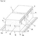
- Fig. 2a shows a perspective view of the support beam 1. It can be seen from this that the elastic damping elements 22 are located on the projections 12a, 12b essentially continuously along the longitudinal direction L.
- FIG. 1 shows a perspective view of the support beam 1. It can be seen from this that the elastic damping elements 22 are located on the projections 12a, 12b essentially continuously along the longitudinal direction L.
- the toothing 6 is designed here, for example, as a periodic longitudinal groove.
- Other embodiments can also provide the toothing outside the longitudinal groove.
- they are arranged at regular intervals along the longitudinal direction Through openings 20 shown through one of which the cross section of Fig. 1 is taken.
- Figure 2b shows another embodiment of the supporting beam 1 with the overhang 4 made of concrete or reinforced concrete and the connecting means formed there in the form of a toothing 6. These can be formed with or without the longitudinal groove.
- Figures 4a and 4b show an embodiment with a fire protection layer 17a, 17b.
- Figure 4a shows an embodiment in which a fire protection layer 17a is provided on the base plate 12, specifically inside the supporting beam 1 between the webs 14, 16.
- a fire protection layer 17b is arranged below the carrier 10 or the base plate 12, ie on the side of the carrier 10 or the base plate 12 facing away from the webs 14, 16.
- the fire protection layer 17b can also have a paint or be a paint itself.
- FIG. 5a shows a further embodiment for composite means according to the invention to achieve a form fit, namely corrugated metal sheets 19.
- corrugated metal sheets are also representative of other deformed sheet metal strips that can transmit composite forces through protrusions / recesses / surface contours. This can be, for example, twisted, folded or plastically deformed areas on the sheet metal strips.
- Figure 5b shows an embodiment in which the composite means according to the invention is realized by a bar or a perforated plate 21, the / the recesses 27 for Has absorption of transverse forces.
- the perforated plate 21 runs parallel to the web 14 and / or 16.
- Figure 5c shows a perforated plate 21 with recesses 27, which is arranged perpendicular to the web 14 and / or 16.
- Fig. 5d shows a further variant of the steel part of the supporting beam, in which the side web design 19, which is designed as a fold / bend, is arranged together with the base plate 12.
- the web 14 and / or 16 has folds and / or bends.
- Fig. 3 shows a ceiling system 100 according to the invention with the supporting beam 1 according to the invention and a semi-finished part 30 which is supported on the supporting beam 1.
- Composite elements 26, in particular reinforcing steel, were passed through the through opening 20 in the supporting beam.
- the connection area between the supporting beam 1 and the semi-finished part 30 is filled with in-situ concrete 50. It is in particular off Fig. 3a It can be seen that the in-situ concrete 50 does not penetrate into the through openings 20 of the supporting beam 1, but the supporting beam 1 is only filled with the concrete 2.
- the supporting beam 1 is first supported on supports (not shown), then the semi-finished part 30 is supported on the supporting beam 1, in particular the projections 12a, 12b.
- the composite elements 26 are then introduced into the through openings 20 of the supporting beam and a connecting area between the supporting beam 1 and the semi-finished part 30 is thus created.
- the in-situ concrete layer 50 is applied in the connection area between the supporting beam and the semi-finished part 30.
- the in-situ concrete 50 only penetrates into the through openings 20 of the supporting beam 1.
- the space between the webs is not filled with in-situ concrete 50 filled up, but has already been filled with concrete 2 during the production of the supporting beam.
- Figure 6 shows an embodiment having a hanger basket 25.
- Reinforcing steel in the form of longitudinal bars 23, 24, which extend in the longitudinal direction L, is arranged therein.
- the bracket cage 25 and the reinforcing steel 23, 24 are surrounded by concrete 2.
- the connecting means 18 extend through gaps in the bracket basket 25, as shown in FIG Figure 6 evident. This can strengthen the composite effect. In other words, the composite means 18 can be anchored even better in the concrete 2.
- the connecting means 18 and the through openings 20 are arranged at the same distance from the base plate 12.
- the composite means 18 and the through openings 20 are also in this embodiment, as for example in FIGS Figures 2a and 2 B for the embodiment of Figure 1 shown, arranged offset from one another in the longitudinal direction L.
- Damping elements 22 can be arranged on the projections 12a, 12b essentially continuously along the longitudinal direction L. Other arrangements of the damping elements 22, in particular those as described above, are also possible.
- the reinforcing bars 23, 24 running in the longitudinal direction L are preferably arranged in two planes, namely the reinforcing bars 23 in a plane E1, which is arranged on the (lower) side of the bracket cage 25 towards the base plate 12, and the reinforcing bars 24 in a plane E2 , which is arranged on the opposite (upper) side of the bracket basket 25, namely on the side of the protrusion 4.
- Six reinforcing bars 24 are preferably arranged in plane E2 and four reinforcing bars 23 are arranged in plane E1, which are located in Extend longitudinal direction L. Any other number is possible depending on the force required.
- the upper level E2 of the reinforcing steel 24 with the concrete 2 forms a reinforced pressure chord of the connecting beam.
Landscapes
- Engineering & Computer Science (AREA)
- Architecture (AREA)
- Civil Engineering (AREA)
- Structural Engineering (AREA)
- Physics & Mathematics (AREA)
- Electromagnetism (AREA)
- Chemical & Material Sciences (AREA)
- Composite Materials (AREA)
- Rod-Shaped Construction Members (AREA)
- Joining Of Building Structures In Genera (AREA)
Applications Claiming Priority (3)
| Application Number | Priority Date | Filing Date | Title |
|---|---|---|---|
| DE202015104628.6U DE202015104628U1 (de) | 2015-09-01 | 2015-09-01 | Tragbalken für Deckensysteme und Deckensystem |
| PCT/EP2016/070498 WO2017037106A1 (fr) | 2015-09-01 | 2016-08-31 | Poutre maîtresse pour structures de plancher, structure de plancher et procédé de fabrication |
| EP16759753.3A EP3344823B2 (fr) | 2015-09-01 | 2016-08-31 | Sommier pour des systèmes de plafonds, un système de plafonds et une méthode de fabrication respective |
Related Parent Applications (2)
| Application Number | Title | Priority Date | Filing Date |
|---|---|---|---|
| EP16759753.3A Division-Into EP3344823B2 (fr) | 2015-09-01 | 2016-08-31 | Sommier pour des systèmes de plafonds, un système de plafonds et une méthode de fabrication respective |
| EP16759753.3A Division EP3344823B2 (fr) | 2015-09-01 | 2016-08-31 | Sommier pour des systèmes de plafonds, un système de plafonds et une méthode de fabrication respective |
Publications (1)
| Publication Number | Publication Date |
|---|---|
| EP3885506A1 true EP3885506A1 (fr) | 2021-09-29 |
Family
ID=56852264
Family Applications (2)
| Application Number | Title | Priority Date | Filing Date |
|---|---|---|---|
| EP21159926.1A Withdrawn EP3885506A1 (fr) | 2015-09-01 | 2016-08-31 | Poutre porteuse pour systèmes de plafond, système de plafond et son procédé de fabrication |
| EP16759753.3A Active EP3344823B2 (fr) | 2015-09-01 | 2016-08-31 | Sommier pour des systèmes de plafonds, un système de plafonds et une méthode de fabrication respective |
Family Applications After (1)
| Application Number | Title | Priority Date | Filing Date |
|---|---|---|---|
| EP16759753.3A Active EP3344823B2 (fr) | 2015-09-01 | 2016-08-31 | Sommier pour des systèmes de plafonds, un système de plafonds et une méthode de fabrication respective |
Country Status (16)
| Country | Link |
|---|---|
| US (1) | US10407910B2 (fr) |
| EP (2) | EP3885506A1 (fr) |
| CN (1) | CN108291401B (fr) |
| CA (1) | CA2996993C (fr) |
| DE (1) | DE202015104628U1 (fr) |
| DK (1) | DK3344823T4 (fr) |
| ES (1) | ES2860674T5 (fr) |
| FI (1) | FI3344823T4 (fr) |
| HU (1) | HUE053574T2 (fr) |
| LT (1) | LT3344823T (fr) |
| MY (1) | MY191103A (fr) |
| PH (1) | PH12018500420B1 (fr) |
| PL (1) | PL3344823T5 (fr) |
| PT (1) | PT3344823T (fr) |
| SG (1) | SG11201801645UA (fr) |
| WO (1) | WO2017037106A1 (fr) |
Families Citing this family (4)
| Publication number | Priority date | Publication date | Assignee | Title |
|---|---|---|---|---|
| NL2020588B1 (nl) * | 2018-03-14 | 2019-09-26 | Mouw Edwin | Liggersamenstel voor composietvloer |
| DE102018212750A1 (de) * | 2018-07-31 | 2020-02-06 | Pfeifer Holding Gmbh & Co. Kg | Tragbalken für Deckensysteme, Deckensystem und Verfahren zu deren Herstellung |
| SE543184C2 (sv) * | 2019-02-14 | 2020-10-20 | Vaestsvenska Staalkonstruktioner Ab | Brandsäker bjälklagsbalk av stål med vertikala liv, horisontella flänsar och ett värmeisolerande material i ett utrymme mellan flänsarna |
| CA3050000A1 (fr) * | 2019-07-16 | 2021-01-16 | Invent To Build Inc. | Poutrelle en acier pouvant etre remplie de beton |
Citations (6)
| Publication number | Priority date | Publication date | Assignee | Title |
|---|---|---|---|---|
| FI980993L (fi) * | 1998-05-05 | 1999-11-06 | Espak Oy | Betoni/teräs-liittorakenteinen leukapalkki |
| WO2007131115A1 (fr) * | 2006-05-04 | 2007-11-15 | Diversakore, Llc | Système d'ossature structurelle en composite et son procédé de construction |
| EP1611295B1 (fr) | 2003-04-10 | 2009-05-13 | Peikko Group Oy | Poutre d'acier |
| WO2011012974A2 (fr) * | 2009-07-29 | 2011-02-03 | Fima Cosma Silos S.P.A. | Procédé de fabrication dune poutre composite préfabriquée dacier et de béton et poutre fabriquée selon ledit procédé |
| KR20120028765A (ko) * | 2010-09-15 | 2012-03-23 | 한국건설기술연구원 | 절곡강판형 강재 보와 데크플레이트를 이용한 합성보 |
| CN104060761B (zh) * | 2014-05-23 | 2016-03-09 | 浙江东南网架股份有限公司 | U形钢混凝土组合截面梁及其施工方法 |
Family Cites Families (31)
| Publication number | Priority date | Publication date | Assignee | Title |
|---|---|---|---|---|
| US2015744A (en) * | 1933-02-20 | 1935-10-01 | American Cyanamid & Chem Corp | Snap locking slab |
| US2222037A (en) * | 1938-02-21 | 1940-11-19 | Robert C Lafferty | Building and building construction |
| US3540116A (en) * | 1967-07-07 | 1970-11-17 | Hauserman Co E F | Method of making a building panel |
| US3810337A (en) * | 1970-10-28 | 1974-05-14 | S Pollard | An elongated stressed structural member |
| US3865914A (en) * | 1971-06-01 | 1975-02-11 | Helmar Nahr | Method of making a composite body consisting of at least two component parts such as profiles |
| GB1431191A (en) | 1973-04-18 | 1976-04-07 | Taylor R | Composite and prestressed concrere structures |
| DE3204590C2 (de) * | 1982-02-10 | 1984-12-20 | Idsteiner Stahl- und Verbundträgerbau GmbH, 6270 Idstein | Verbundträger |
| DE3204890A1 (de) | 1982-02-12 | 1983-08-25 | Peter 7300 Esslingen Witkowski | "beschickungs- und/oder entnahmevorrichtung fuer waermebehandlungsoefen" |
| US4580380A (en) * | 1983-11-07 | 1986-04-08 | Ballard Derryl R | Composite filled interior structural box beams |
| SE457364B (sv) * | 1987-05-11 | 1988-12-19 | Joergen Thor | Brandmotstaandskraftig bjaelklagsbalk av staal i samverkan med betong |
| SE462436B (sv) | 1988-10-18 | 1990-06-25 | Rautaruukki Ab | Balk foer upplaeggning och foerankring av bjaelklag och/eller pelare samt saett att tillverka saadan balk |
| FI85745C (fi) | 1989-04-13 | 1993-02-23 | Peikkorakenne Oy | Brandsaeker prefabricerad staolbalk |
| FI990662L (fi) | 1999-03-25 | 2000-09-26 | Teraeselementti Oy | Palkki |
| AUPQ376399A0 (en) * | 1999-10-29 | 1999-11-25 | Cds Nu-Steel Pty Ltd | A structural member |
| ES2165309B1 (es) * | 2000-02-23 | 2003-05-16 | Nina Marino E Sanchez | Disposicion mejorada para la configuracion de elementos constructivos. |
| AU754130B1 (en) | 2001-06-05 | 2002-11-07 | Bonacci Beam Pty Ltd | Building structural element |
| FI20021934L (fi) * | 2002-10-31 | 2004-07-16 | Tartuntamarkkinointi Oy | Liittopalkki |
| EP1579077A4 (fr) * | 2002-12-30 | 2008-10-22 | Koo Min Se | Poutre mixte precontrainte, structure de poutre mixte precontrainte en continu et procedes de fabrication et de raccordement correspondants |
| US7814719B2 (en) * | 2004-06-14 | 2010-10-19 | Plastedil S.A. | Self-supporting construction element made of expanded plastic material, in particular for manufacturing building floors and floor structure incorporating such element |
| DE202004018655U1 (de) * | 2004-12-02 | 2005-04-21 | Velthorst Beheer B.V. | Stahlverbundträger mit brandgeschütztem Auflager für Deckenelemente |
| NL1031896C1 (nl) | 2006-05-29 | 2007-11-30 | Anne Pieter Van Driesum | Ligger voor het ondersteunen van vloerplaten, alsmede bodemplaat, combinatieplaat of ondersteuningsstaaf als deel van een dergelijke ligger. |
| DE102010025042A1 (de) | 2010-06-22 | 2011-12-22 | Deltastaal B.V. | Stahlträger für Fertigteildecken |
| KR101233931B1 (ko) * | 2010-09-30 | 2013-02-15 | 김충기 | 조립식 지지빔구조체 및 조립식 지지빔구조체의 설치방법 |
| CN103452188B (zh) * | 2012-04-25 | 2015-07-08 | 株式会社Drb东一 | 利用u形组合梁的层高减小型钢构架 |
| CN103061443B (zh) | 2012-12-31 | 2016-08-03 | 合肥工业大学 | 一种外包钢-混凝土叠合板组合梁 |
| CN203440994U (zh) | 2013-06-28 | 2014-02-19 | 武汉弘毅鸿幕墙工程有限公司 | 一种波纹腹板工字型钢混凝土复合扁平梁 |
| CN103388376B (zh) | 2013-08-22 | 2015-11-11 | 四川大学 | 一种提高抗疲劳强度的波形钢腹板梁结构 |
| CN203669205U (zh) | 2014-01-02 | 2014-06-25 | 常州工程职业技术学院 | 一种外包钢组合梁 |
| CN103835435B (zh) | 2014-03-07 | 2016-04-27 | 江苏中宝钢构有限公司 | 一种u形钢-混凝土组合梁 |
| CN104264899B (zh) * | 2014-10-17 | 2016-05-11 | 上海天华建筑设计有限公司 | 嵌入式外包u形钢-混凝土组合梁 |
| KR101567741B1 (ko) * | 2015-02-16 | 2015-11-09 | 권용근 | 조립트러스 매립형 합성보 |
-
2015
- 2015-09-01 DE DE202015104628.6U patent/DE202015104628U1/de not_active Expired - Lifetime
-
2016
- 2016-08-31 EP EP21159926.1A patent/EP3885506A1/fr not_active Withdrawn
- 2016-08-31 US US15/756,492 patent/US10407910B2/en active Active
- 2016-08-31 SG SG11201801645UA patent/SG11201801645UA/en unknown
- 2016-08-31 EP EP16759753.3A patent/EP3344823B2/fr active Active
- 2016-08-31 PL PL16759753.3T patent/PL3344823T5/pl unknown
- 2016-08-31 MY MYPI2018000305A patent/MY191103A/en unknown
- 2016-08-31 PH PH1/2018/500420A patent/PH12018500420B1/en unknown
- 2016-08-31 LT LTEP16759753.3T patent/LT3344823T/lt unknown
- 2016-08-31 HU HUE16759753A patent/HUE053574T2/hu unknown
- 2016-08-31 ES ES16759753T patent/ES2860674T5/es active Active
- 2016-08-31 FI FIEP16759753.3T patent/FI3344823T4/fi active
- 2016-08-31 CA CA2996993A patent/CA2996993C/fr active Active
- 2016-08-31 DK DK16759753.3T patent/DK3344823T4/da active
- 2016-08-31 PT PT167597533T patent/PT3344823T/pt unknown
- 2016-08-31 WO PCT/EP2016/070498 patent/WO2017037106A1/fr not_active Ceased
- 2016-08-31 CN CN201680050724.4A patent/CN108291401B/zh active Active
Patent Citations (6)
| Publication number | Priority date | Publication date | Assignee | Title |
|---|---|---|---|---|
| FI980993L (fi) * | 1998-05-05 | 1999-11-06 | Espak Oy | Betoni/teräs-liittorakenteinen leukapalkki |
| EP1611295B1 (fr) | 2003-04-10 | 2009-05-13 | Peikko Group Oy | Poutre d'acier |
| WO2007131115A1 (fr) * | 2006-05-04 | 2007-11-15 | Diversakore, Llc | Système d'ossature structurelle en composite et son procédé de construction |
| WO2011012974A2 (fr) * | 2009-07-29 | 2011-02-03 | Fima Cosma Silos S.P.A. | Procédé de fabrication dune poutre composite préfabriquée dacier et de béton et poutre fabriquée selon ledit procédé |
| KR20120028765A (ko) * | 2010-09-15 | 2012-03-23 | 한국건설기술연구원 | 절곡강판형 강재 보와 데크플레이트를 이용한 합성보 |
| CN104060761B (zh) * | 2014-05-23 | 2016-03-09 | 浙江东南网架股份有限公司 | U形钢混凝土组合截面梁及其施工方法 |
Also Published As
| Publication number | Publication date |
|---|---|
| ES2860674T3 (es) | 2021-10-05 |
| SG11201801645UA (en) | 2018-03-28 |
| DK3344823T3 (da) | 2021-03-29 |
| CA2996993A1 (fr) | 2017-03-09 |
| MY191103A (en) | 2022-05-30 |
| LT3344823T (lt) | 2021-04-12 |
| ES2860674T5 (en) | 2025-02-12 |
| PL3344823T5 (pl) | 2024-06-03 |
| PL3344823T3 (pl) | 2021-08-02 |
| EP3344823A1 (fr) | 2018-07-11 |
| CN108291401A (zh) | 2018-07-17 |
| FI3344823T4 (fi) | 2024-05-15 |
| DK3344823T4 (da) | 2024-05-21 |
| DE202015104628U1 (de) | 2016-12-05 |
| PH12018500420B1 (en) | 2024-06-21 |
| US10407910B2 (en) | 2019-09-10 |
| HK1256302A1 (zh) | 2019-09-20 |
| US20180291626A1 (en) | 2018-10-11 |
| CA2996993C (fr) | 2023-10-03 |
| HUE053574T2 (hu) | 2021-07-28 |
| PH12018500420A1 (en) | 2018-08-29 |
| WO2017037106A1 (fr) | 2017-03-09 |
| EP3344823B2 (fr) | 2024-04-17 |
| PT3344823T (pt) | 2021-04-06 |
| CN108291401B (zh) | 2021-03-16 |
| EP3344823B1 (fr) | 2021-03-03 |
Similar Documents
| Publication | Publication Date | Title |
|---|---|---|
| EP3344823B1 (fr) | Sommier pour des systèmes de plafonds, un système de plafonds et une méthode de fabrication respective | |
| DE3128165C2 (de) | Schalldämmendes Wandbausystem für Industriebauten, sowie Kassettenprofil hierfür | |
| EP1737778A2 (fr) | Escalier roulant ou trottoir roulant | |
| EP3574160B1 (fr) | Élément de construction hybride en béton poreux | |
| EP0023042B1 (fr) | Elément de plancher préfabriqué pour planchers de bâtiments | |
| EP2984251B1 (fr) | Lame de revêtement pour échafaudages | |
| DE2616058C2 (de) | Blechprofilträger für Dachkonstruktionen | |
| EP0627531B1 (fr) | Elément de support pour éléments de construction | |
| EP1669505B1 (fr) | Poutre composite en acier-béton avec support ignifuge pour éléments de plafond | |
| DE4000956C2 (de) | Element für den Großtafelbau aus Beton | |
| EP2459812B1 (fr) | Élément de béton armé à armature formée d'éléments de tôle en z | |
| AT503358B1 (de) | Anschlusskorb für vorfabrizierte doppelwandelemente | |
| DE102018130460B4 (de) | Stoßfängeranordnung für ein Kraftfahrzeug | |
| DE202020100059U1 (de) | Schalungselement | |
| DE2141046A1 (de) | Bewehrungselement fuer vorgefertigte duennschalige grossflaechen-stahlbetonverbundplatten | |
| WO1992003624A1 (fr) | Profile en acier pour constructions en ossature metallique | |
| DE60115587T2 (de) | Decke für eine Gebäudekonstruktion bestehend aus U-förmigen Metallprofilen | |
| DE2250505C3 (de) | Raumzelle für Bauwerke | |
| AT270962B (de) | Vorgefertigtes, großformatiges, dünnwandiges Stahlbeton-Tafelelement | |
| DE29922297U1 (de) | Stahl-Beton-Decke | |
| DE1805968A1 (de) | Verfahren zur Herstellung vorgefertigter,belastbarer Wandbauteile | |
| DE19822417C2 (de) | Bauteil mit erhöhter Festigkeit | |
| DE102022004941A1 (de) | Verankerungssystem in der Bauindustrie | |
| EP4450723A1 (fr) | Raccord pour éléments de construction en béton | |
| DE7930691U1 (de) | Raeumlicher gittertraeger |
Legal Events
| Date | Code | Title | Description |
|---|---|---|---|
| PUAI | Public reference made under article 153(3) epc to a published international application that has entered the european phase |
Free format text: ORIGINAL CODE: 0009012 |
|
| STAA | Information on the status of an ep patent application or granted ep patent |
Free format text: STATUS: THE APPLICATION HAS BEEN PUBLISHED |
|
| AC | Divisional application: reference to earlier application |
Ref document number: 3344823 Country of ref document: EP Kind code of ref document: P |
|
| AK | Designated contracting states |
Kind code of ref document: A1 Designated state(s): AL AT BE BG CH CY CZ DE DK EE ES FI FR GB GR HR HU IE IS IT LI LT LU LV MC MK MT NL NO PL PT RO RS SE SI SK SM TR |
|
| STAA | Information on the status of an ep patent application or granted ep patent |
Free format text: STATUS: REQUEST FOR EXAMINATION WAS MADE |
|
| 17P | Request for examination filed |
Effective date: 20220329 |
|
| RBV | Designated contracting states (corrected) |
Designated state(s): AL AT BE BG CH CY CZ DE DK EE ES FI FR GB GR HR HU IE IS IT LI LT LU LV MC MK MT NL NO PL PT RO RS SE SI SK SM TR |
|
| P01 | Opt-out of the competence of the unified patent court (upc) registered |
Effective date: 20230525 |
|
| STAA | Information on the status of an ep patent application or granted ep patent |
Free format text: STATUS: THE APPLICATION HAS BEEN WITHDRAWN |
|
| 18W | Application withdrawn |
Effective date: 20231129 |