EP3885666A1 - Absperrvorrichtung für den einsatz in einer luftleitung einer raumlufttechnischen anlage oder einer maschinellen entrauchungsanlage - Google Patents
Absperrvorrichtung für den einsatz in einer luftleitung einer raumlufttechnischen anlage oder einer maschinellen entrauchungsanlage Download PDFInfo
- Publication number
- EP3885666A1 EP3885666A1 EP20165682.4A EP20165682A EP3885666A1 EP 3885666 A1 EP3885666 A1 EP 3885666A1 EP 20165682 A EP20165682 A EP 20165682A EP 3885666 A1 EP3885666 A1 EP 3885666A1
- Authority
- EP
- European Patent Office
- Prior art keywords
- shut
- coating
- housing
- medium
- flap
- Prior art date
- Legal status (The legal status is an assumption and is not a legal conclusion. Google has not performed a legal analysis and makes no representation as to the accuracy of the status listed.)
- Granted
Links
Images

Classifications
-
- F—MECHANICAL ENGINEERING; LIGHTING; HEATING; WEAPONS; BLASTING
- F24—HEATING; RANGES; VENTILATING
- F24F—AIR-CONDITIONING; AIR-HUMIDIFICATION; VENTILATION; USE OF AIR CURRENTS FOR SCREENING
- F24F13/00—Details common to, or for air-conditioning, air-humidification, ventilation or use of air currents for screening
- F24F13/08—Air-flow control members, e.g. louvres, grilles, flaps or guide plates
- F24F13/10—Air-flow control members, e.g. louvres, grilles, flaps or guide plates movable, e.g. dampers
- F24F13/14—Air-flow control members, e.g. louvres, grilles, flaps or guide plates movable, e.g. dampers built up of tilting members, e.g. louvre
- F24F13/1426—Air-flow control members, e.g. louvres, grilles, flaps or guide plates movable, e.g. dampers built up of tilting members, e.g. louvre characterised by actuating means
-
- A—HUMAN NECESSITIES
- A62—LIFE-SAVING; FIRE-FIGHTING
- A62C—FIRE-FIGHTING
- A62C2/00—Fire prevention or containment
- A62C2/06—Physical fire-barriers
- A62C2/12—Hinged dampers
-
- F—MECHANICAL ENGINEERING; LIGHTING; HEATING; WEAPONS; BLASTING
- F24—HEATING; RANGES; VENTILATING
- F24F—AIR-CONDITIONING; AIR-HUMIDIFICATION; VENTILATION; USE OF AIR CURRENTS FOR SCREENING
- F24F11/00—Control or safety arrangements
- F24F11/30—Control or safety arrangements for purposes related to the operation of the system, e.g. for safety or monitoring
- F24F11/32—Responding to malfunctions or emergencies
- F24F11/33—Responding to malfunctions or emergencies to fire, excessive heat or smoke
- F24F11/35—Responding to malfunctions or emergencies to fire, excessive heat or smoke by closing air passages
-
- F—MECHANICAL ENGINEERING; LIGHTING; HEATING; WEAPONS; BLASTING
- F24—HEATING; RANGES; VENTILATING
- F24F—AIR-CONDITIONING; AIR-HUMIDIFICATION; VENTILATION; USE OF AIR CURRENTS FOR SCREENING
- F24F13/00—Details common to, or for air-conditioning, air-humidification, ventilation or use of air currents for screening
- F24F13/08—Air-flow control members, e.g. louvres, grilles, flaps or guide plates
- F24F13/10—Air-flow control members, e.g. louvres, grilles, flaps or guide plates movable, e.g. dampers
- F24F13/14—Air-flow control members, e.g. louvres, grilles, flaps or guide plates movable, e.g. dampers built up of tilting members, e.g. louvre
Definitions
- the invention relates to a shut-off device for use in an air line of a ventilation system or a mechanical smoke extraction system, the shut-off device having a housing through which a gaseous medium flows, preferably a square cross-section, and a housing wall mounted in the housing so as to be pivotable about a pivot axis Includes damper blade.
- shut-off devices In their closed position, shut-off devices should close the flow cross-section of the air line and prevent the gaseous medium from flowing. If the shut-off device is designed as a fire damper, the damper blade is made of calcium silicate. Corresponding shut-off devices can indeed be used in air lines for ventilation of, for example, living or work rooms, but not in atmospheres that, planned or unscheduled, exert a damaging and / or corrosion-causing effect on the shut-off device due to chemical reactions, since the areas of the Shut-off devices that are in contact with the medium flowing in the housing can be attacked by a chemically aggressive gaseous medium.
- the object of the invention is to avoid the above-mentioned disadvantages and to provide a shut-off device that is harmful even in atmospheres that are scheduled or unscheduled due to chemical reactions and / or exert corrosion of metallic and non-metallic materials causing effect on the shut-off device, can be used.
- shut-off device for use of the shut-off device in connection with a chemically aggressive gaseous medium, at least all areas of the shut-off device that are in contact with the medium flowing in the housing are protected against damaging chemical reactions with this medium or due to this medium, are designed to be resistant, the resistance being formed either by the material of the areas coming into contact with the flowing medium themselves or by a coating applied to the areas coming into contact with the flowing medium.
- the pivot axis can be formed by a stationary axis or by a shaft which is non-rotatable with respect to the flap leaf.
- the axle or the shaft can be coated with Teflon, for example.
- the shut-off device according to the invention therefore has no metallic surfaces, at least in the areas that are in contact with the medium flowing in the housing.
- a chemically aggressive gaseous medium is understood as meaning, for example, contaminated and aggressive exhaust air, for example from laboratories and laboratory fume cupboards, from the chemical industry, from electroplating or from the automotive industry.
- This exhaust air can be chemically contaminated with a wide variety of substances, some of which are very aggressive, such as acids or bases. However, it can also be exhaust air from commercial kitchens.
- shut-off device which is, for example, a fire damper, can be used safely as long as one conventional shut-off device designed as a fire damper in an air line for ventilation of, for example, living or work rooms.
- all areas is understood to mean the areas / components of the shut-off device which come into contact with the flowing medium and which are relevant for the function of the shut-off device. These are, for example, the inside of the housing wall, the flap leaf, the bearing or the like. However, it can also be the outside (s) of the shut-off device, which is (are) used, for example, in a laboratory room.
- the flap leaf can for example consist of calcium silicate, for example a calcium silicate plate, or of metal. All areas of the surface of the valve blade that come into contact with the flowing medium are provided with the coating according to the invention.
- the areas themselves that come into contact with the flowing medium or the applied coating can also offer additional protection against mechanical loads.
- particles can be contained in the flowing medium which have an abrasive effect on areas of the shut-off device located within the housing. Either through the material of the areas that come into contact with the flowing medium itself or through a coating applied to the areas that come into contact with the flowing medium, the shut-off device can thus also be used, for example, in atmospheres with a high concentration of particles.
- a two- or more-component epoxy resin coating can be provided as the coating.
- Such a coating is suitable for use in very aggressive chemical media.
- Such a two-component epoxy resin coating is available, for example, under the name Sikafloor®-381.
- Sikafloor®-381 is available, for example, under the name Sikafloor®-381.
- such a coating has good surface protection (mechanical strength) and hardens quickly.
- the coating can be solvent-free in the cured state.
- the coating can be reinforced with ceramic.
- ceramic Such a two-component epoxy resin coating is available under the name LOCTITE® PC 7255 TM. Such a coating ensures good protection of surfaces even in very aggressive chemical media. Since the coating is reinforced with ceramic, the surface provided with the coating is not only well protected against corrosive substances, but also against abrasive substances.
- the coating can be sprayable. Alternatively, the coating can be applied mechanically.
- a primer is provided between the respective area and the coating.
- Calcium silicate has a very uneven and rough surface. Calcium silicate also absorbs liquids strongly.
- the surface of a calcium silicate plate for example, is closed at least to a large extent, preferably completely, so that the coating only needs to be applied in a small amount.
- the primer improves the adhesion of the subsequently applied coating.
- At least a partial area of the housing wall can be formed from at least one fire protection building board or at least one cement-bound calcium silicate board.
- the thickness of the housing wall can preferably be between 10 mm and 80 mm be. If the housing has a square cross-section, the housing wall consists of four housing wall sections which are correspondingly fixed to one another. Each housing wall section can be formed, for example, from a fire protection board or a cement-bound calcium silicate board. Of course, other materials that are sufficiently temperature-resistant are also conceivable.
- the flap leaf can be formed from at least one fire protection building board or a cement-bound calcium silicate board.
- fire protection building board or a cement-bound calcium silicate board.
- other materials that are sufficiently temperature-resistant are also conceivable.
- the shut-off device can be designed as a smoke extraction flap.
- Smoke control dampers are used to keep building areas in a building, for example an escape area, free of smoke.
- the area of application of a smoke control damper is at a temperature between the ambient temperature of the building area to be kept smoke-free (cold smoke extraction) and a temperature of up to 1000 ° C or more (hot smoke extraction).
- smoke control dampers must ensure a cold seal on the one hand and a warm seal on the other. Due to the possibly high temperatures, the housing, the flap, the stops and the encapsulation of the drive device arranged on the outside of the housing usually consist of calcium silicate.
- Smoke control dampers are usually triggered by a smoke detector. Of course, other triggering devices, such as. B.
- Smoke control dampers are designed in such a way that subsequent opening, ie pivoting into the open position, is guaranteed even after they have been triggered, ie after pivoting from the open position into the closed position. Of course, this also applies to the reverse case.
- the shut-off device can also be designed as a fire damper.
- Fire dampers usually have a housing made of metal or of calcium silicate plates, in which a damper blade made of calcium silicate is pivotably mounted.
- a fire damper can be operated manually, for example.
- an operating handle is provided.
- the flap leaf can be fixed in its open position by means of a fixing device against a restoring force and can be pivoted from the fixed position, for example in the event of fire, into its closed position after the fixing device has been released by the restoring force.
- the restoring force can be generated by a spring, preferably arranged outside the housing.
- the fixing device is designed, for example, as a fusible link.
- the flap leaf is fixed in its open position by means of the fixing device against a restoring force. For example in the event of a fire, i. H. if the temperature exceeds a value of about 72 ° C, the flap leaf is pivoted from its fixed open position after triggering the fixing device, for example the fusible link, by the restoring force provided by the spring from its open position to its closed position.
- an intumescent material expands, i. H. a material that foams when exposed to heat.
- the intumescent material now completely fills any gap that may still exist, for example between the housing and the valve leaf in its closed position.
- the flap can no longer be opened and must be replaced later.
- other configurations such as a thermoelectric triggering device, are also conceivable as fixing devices.
- shut-off device can also be designed as a combined fire protection and smoke extraction flap.
- a drive device acts directly or indirectly on the flap leaf. This allows the damper blade to be moved into the desired position by a motor.
- the drive device is designed, for example, as a spring return motor.
- a spring in the spring return motor is tensioned.
- a thermoelectric release device which can be an electric fusible link, for example, causes a voltage interruption.
- the spring return motor can thus no longer counteract the restoring force generated by the tensioned spring, so that the flap leaf is closed by the restoring force applied by the spring.
- an OPEN / CLOSE drive can also be used as a drive device for opening and closing the damper blade.
- the OPEN / CLOSE actuator provides a maximum torque of 40 Nm.
- the limit switches for the OPEN and CLOSED position indicators are usually located inside the OPEN / CLOSE actuator.
- the OPEN / CLOSE drive is controlled via a suitable interface monitoring unit with a control module.
- the interface monitoring unit supplies the OPEN / CLOSE actuator with voltage and monitors whether the safety position has been reached. It also guarantees that the damper blade closes in the event of a voltage drop in a building.
- the OPEN / CLOSE drive is controlled, for example, via a control module. If the control module includes double-layer capacitors, the double-layer capacitors provide a redundant 24 V voltage supply.
- thermoelectric trigger element can be connected to an input of the control module in a fail-safe manner. In the event of a thermal release, the control module closes the damper blade. If the 24V power supply is interrupted, the damper blade is also closed by the energy of the double-layer capacitors.
- the control module is preferably located within an encapsulation of the OPEN / CLOSE drive and is connected to a controller unit by means of two-wire technology, for example.
- the controller unit consists of a controller including suitable control software and a suitable AS-Interface Power supply unit for communication with the control module.
- the protocol that exchanges the data between the control module and the controller has been internationally standardized according to EN 50295 and IEC 62026-2 since 1999.
- the data transmission and the power supply for the control of the OPEN / CLOSE drive take place, for example, via a two-wire line.
- By evaluating the end positions in the OPEN / CLOSE drive both the position and the running time of the damper blade can be monitored.
- the control module can also be used as a "stand-alone variant”. Then there is no communication with the controller.
- the manual opening and closing of the damper blade takes place via an input contact on the control module.
- a smoke extraction damper comprises a motorized drive device
- a voltage is required both for pivoting the damper blade from the open position into its closed position and for pivoting the damper blade from the closed position into its open position.
- At least one screw preferably extending through the pivot axis, can be provided.
- a receptacle preferably a milled receptacle, can be provided in at least one surface of the valve leaf for receiving the end of the screw located in the area of this surface of the valve leaf.
- At least one receptacle can be closed with a cover, preferably fastened to the flap leaf by means of screws.
- the cover can be a calcium silicate plate, for example. With such a configuration, the coating also covers the cover.
- the shut-off device can comprise an energy store.
- This can be, for example, a battery or an accumulator.
- the energy store can also be designed as a capacitor that is charged when a voltage is applied. If, for example, an electrically operated drive device is provided, the flap leaf can in this case be pivoted from the open position into its closed position or, conversely, from the closed position into its open position even in the event of a voltage interruption.
- the figures show a shut-off device with a housing 2 having a circumferential housing wall 1.
- the housing 2 has a square cross-sectional area.
- the housing wall 1 thus consists of a total of four housing wall sections which are fixed to one another, for example by means of screws (not shown).
- a flap leaf 5 is provided which is pivotably mounted about a pivot axis 3 in the direction of the arrow 4.
- the pivot axis 3 is arranged centrally in relation to the flap leaf 5.
- a seal (not shown) is provided between the flap leaf 5 and the housing wall 1.
- the flap leaf 5 is fastened in a rotationally fixed manner with respect to the pivot axis 3.
- the screw 16 extends through the pivot axis 3.
- the shut-off device is designed as a fire damper.
- Both the housing wall 1 of the housing 2 and the valve leaf 5 consist of calcium silicate plates.
- shut-off device As will be explained below, all areas and components of the shut-off device which are in contact with the gaseous medium flowing in the housing 2 are protected against damaging chemical reactions and / or damaging corrosion by a coating 17.
- the shut-off device is therefore also suitable for influencing the flow of chemically aggressive gaseous media and can be used in this respect, for example, in an exhaust air line of a laboratory or a laboratory fume cupboard.
- a stop 7 is provided on the inside of the housing 2.
- the stops 7 with their coating 17 applied on both sides are offset from one another and on opposite sides of the housing 2 by about the thickness of the flap leaf 5, which has the coating 17 on all sides, when viewed in the flow direction 6, and are arranged on the adjacent one by means of screws covered by the coating 17 Housing wall 1 attached.
- Each stop 7 is approximately U-shaped and consists of a base section 8 which is arranged parallel to the pivot axis 3.
- a side section 9 adjoins each of the two ends of each base section 8. The length of each side section 9 is coordinated such that the flap leaf 5 is aligned parallel to the flow direction 6 in the open position. In this position, the flap leaf 5 can touch all four free ends of the side sections 9. In such a configuration, the four ends of the side sections 9 define the open position of the flap leaf 5.
- each stop 7 has a recess 10 on the side facing the flap leaf 5 in its closed position, which in the illustrated embodiment has a square cross-section.
- Each recess 10 is formed by a protruding area 11 of the stop 7 and by the adjoining housing wall 1.
- a seal 12 is provided which completely fills the recess 10 and which also protrudes from the recess 10 and thus protrudes from the stop 7.
- Each recess 10 extends over the entire length of the base section 8 and the two side sections 9 of the relevant stop 7.
- the areas of the seal 12 that come into contact with the flowing medium are also provided with the coating 17.
- the flap leaf 5 rests against a stop 18 which is fastened to the housing wall 1 by means of screws that cannot be seen.
- the surfaces of the stop 18 that come into contact with the flowing medium are also provided with the coating 17.
- the coating 17 covers all surfaces of the areas / components of the shut-off device that are in contact with the medium flowing in the housing 2.
- the inside of the housing wall 1 is also provided with the coating 17.
- a recess 13 is provided in the partial area cooperating with the seal 12 in the closed position, which in the closed position of the flap leaf 5 completely accommodates the part of the seal 12 protruding from the stop 7 in the illustrated case.
- the valve leaf 5 touches the projecting area 11 of the stop 7 in its closed position. If a gap remains between the projecting area 11 of the stop 7 and the valve leaf 5 in the closed position of the valve leaf 5, this is at least reduced to a minimum.
- the recess 10 provided in the stop 7 and the recess 13 corresponding in the flap leaf 5 form a rectangular overall cross-sectional area.
- the seal 12 is preferably full circumference, i. H. covered on all four sides with a non-combustible layer, in particular designed as a coated glass fabric.
- This layer consists, for example, of a material that has a melting point of more than 1000 ° Celsius, preferably more than 1400 ° Celsius.
- it can be a fleece made of alkaline earth silicate wool. This is a high temperature glass wool.
- Fig. 1 It can be seen that in each of the four housing wall sections at least one mounting surface 14 produced by milling with at least one contact edge 15 is introduced.
- the contact edge 15 allows optimal assembly and simple alignment of the stop 7 with respect to the flap leaf 5.
- Fig. 2 shows an outside of the shut-off device. So a drive device 34 is provided on this outside, which by means of screws 19 on the Outside of the housing 2 is attached. The drive device 34 interacts with the pivot axis 3. In order to be able to recognize the position of the flap leaf 5 from the outside, a position indicator 20 is provided.
- a module 21 is provided which is mounted on a bracket 23 fastened to the housing 2 by means of screws 22.
- a square enclosure 24, which is fastened to the housing 2 with screws 25, is provided.
- the encapsulation 24 consists of five calcium silicate plates and, together with the adjoining housing wall 1, forms a closed space in which the drive device 34 and the module 21 are arranged.
- a thermal release element 26 with a detection area 32 is provided on the outside of the housing 2. As in Fig. 1 is shown, the detection area 32 extends through the housing wall 1 and to that extent protrudes into the housing 2.
- the trigger element 26 is connected to the drive device 34 and the module 21 via a cable 33.
- an inspection cover 27 is provided in each of two opposite housing wall sections of the housing 2 and is fastened to the respective housing wall section by means of screws 28.
- Fig. 3 is the detail "Z" from Fig. 1 shown.
- the flap leaf 5 has a continuous recess through which the pivot axis 3 is guided.
- the screw 16 is provided for the rotationally fixed fixing of the flap leaf 5 with respect to the pivot axis 3.
- a milling 35 is provided in both surfaces of the flap leaf 5 on both sides of the continuous recess through which the pivot axis 3 is guided.
- One milling 35 is so deep that it receives a plate 36 and the head of the screw 16, while the opposite milling 35 receives a plate 29.
- An internal thread into which the screw 16 is screwed is provided in the plate 29.
- the plates 36, 29 are made of metal and serve to distribute forces.
- Each milling 35 is covered with a cover 30, each cover 30 being fastened to the flap leaf 5 by means of screws 31.
- Each cover 30 serves as thermal protection for the fastening located underneath in the form of the screw 16.
- the covers 30 can for example consist of calcium silicate plates.
- the coating 17 also extends over the covers 30, so that the flap leaf 5 is completely coated.
Landscapes
- Engineering & Computer Science (AREA)
- Chemical & Material Sciences (AREA)
- Combustion & Propulsion (AREA)
- Mechanical Engineering (AREA)
- General Engineering & Computer Science (AREA)
- Health & Medical Sciences (AREA)
- Public Health (AREA)
- Business, Economics & Management (AREA)
- Emergency Management (AREA)
- Air-Flow Control Members (AREA)
Abstract
Description
- Die Erfindung betrifft eine Absperrvorrichtung für den Einsatz in einer Luftleitung einer raumlufttechnischen Anlage oder einer maschinellen Entrauchungsanlage, wobei die Absperrvorrichtung ein, vorzugsweise einen viereckigen Querschnitt aufweisendes, von einem gasförmigen Medium durchströmtes Gehäuse mit einer Gehäusewandung und ein in dem Gehäuse um eine Schwenkachse herum schwenkbar gelagertes Klappenblatt umfasst.
- Absperrvorrichtungen sollen in ihrer Schließstellung den Strömungsquerschnitt der Luftleitung verschließen und ein Strömen des gasförmigen Mediums verhindern. Sofern die Absperrvorrichtung als Brandschutzklappe ausgebildet ist, besteht das Klappenblatt aus Kalzium-Silikat. Entsprechende Absperrvorrichtungen können zwar in Luftleitungen zur Be- und Entlüftung von beispielsweise Wohn- oder Arbeitsräumen, jedoch nicht in Atmosphären, die planmäßig oder außerplanmäßig aufgrund chemischer Reaktionen eine schädigende und/oder Korrosion verursachende Wirkung auf die Absperrvorrichtung ausüben, eingesetzt werden, da die Bereiche der Absperrvorrichtung, die mit dem in dem Gehäuse strömenden Medium in Kontakt sind, durch ein chemisch aggressives gasförmiges Medium angegriffen werden.
- Aufgabe der Erfindung ist es, die vorgenannten Nachteile zu vermeiden und eine Absperrvorrichtung anzugeben, die auch in Atmosphären, die planmäßig oder außerplanmäßig aufgrund chemischer Reaktionen eine schädigende und/oder Korrosion von metallischen und nicht metallischen Werkstoffen verursachende Wirkung auf die Absperrvorrichtung ausüben, eingesetzt werden kann.
- Diese Aufgabe wird dadurch gelöst, dass für eine Verwendung der Absperrvorrichtung in Verbindung mit einem chemisch aggressiven gasförmigen Medium zumindest sämtliche Bereiche der Absperrvorrichtung, die mit dem in dem Gehäuse strömenden Medium in Kontakt sind, gegen schädigende chemische Reaktionen mit diesem Medium oder aufgrund dieses Mediums, beständig ausgebildet sind, wobei die Beständigkeit entweder durch das Material der mit dem strömenden Medium in Kontakt kommenden Bereiche selbst oder durch eine auf die mit dem strömenden Medium in Kontakt kommenden Bereiche aufgebrachte Beschichtung gebildet ist. Die Schwenkachse kann durch eine feststehende Achse oder durch eine Welle, die drehfest gegenüber dem Klappenblatt ist, gebildet sein. Die Achse oder die Welle können beispielsweise teflonbeschichtet sein. Damit weist die erfindungsgemäße Absperrvorrichtung zumindest in den Bereichen, die mit dem in dem Gehäuse strömenden Medium in Kontakt sind, keine metallischen Oberflächen auf.
- Unter einem chemisch aggressiven gasförmigen Medium wird beispielsweise belastete und aggressive Abluft beispielsweise aus Laboren und Laborabzügen, aus der chemischen Industrie, aus der Galvanik oder aus der Automobilindustrie verstanden. Diese Abluft kann mit den unterschiedlichsten, teils sehr aggressiven, Stoffen, wie beispielsweise Säuren oder Basen, chemisch belastetet sein. Es kann sich jedoch auch um Abluft von gewerblichen Küchen handeln.
- Bei der erfindungsgemäßen Ausgestaltung wird entweder durch das Material der mit dem strömenden Medium in Kontakt kommenden Bereiche selbst oder durch eine auf die mit dem strömenden Medium in Kontakt kommenden Bereiche aufgebrachte Beschichtung verhindert, dass die mit dem strömenden Medium in Kontakt kommenden Bereiche durch das chemisch aggressive gasförmige Medium angegriffen werden. Sämtliche Bereiche der Absperrvorrichtung, die mit dem in dem Gehäuse strömenden Medium in Kontakt sind, sind damit beständig gegen die in der Absperrvorrichtung herrschende Atmosphäre. In Folge der Beständigkeit wird damit eine chemische Reaktion, initiiert durch das chemisch aggressive gasförmige Medium, verhindert, zumindest jedoch auf ein Minimum reduziert, so dass die erfindungsgemäße Absperrvorrichtung, bei der es sich beispielsweise um eine Brandschutzklappe handelt, genauso lange sicher einsetzbar ist wie eine herkömmliche als Brandschutzklappe ausgebildete Absperrvorrichtung in einer Luftleitung zur Be- und Entlüftung von beispielsweise Wohn- oder Arbeitsräumen.
- Unter der Formulierung "sämtliche Bereiche" werden die Bereiche/Bestandteile der Absperrvorrichtung verstanden, die mit dem strömenden Medium in Kontakt kommen und die für die Funktion der Absperrvorrichtung von Relevanz sind. Dies sind beispielsweise die Innenseite der Gehäusewandung, das Klappenblatt, die Lagerung oder dergleichen. Es kann sich aber auch um die Außenseite(n) der Absperrvorrichtung, die beispielsweise in einem Laborraum eingesetzt ist (sind), handeln.
- Das Klappenblatt kann beispielsweise aus Kalzium-Silikat, beispielsweise einer Kalzium-Silikat-Platte, oder aus Metall bestehen. Sämtliche mit dem strömenden Medium in Kontakt kommenden Bereiche der Oberfläche des Klappenblattes sind mit der erfindungsgemäßen Beschichtung versehen.
- Neben einem Schutz gegen schädigende chemische Reaktionen durch das chemisch aggressive gasförmige Medium können die mit dem strömenden Medium in Kontakt kommenden Bereiche selbst oder die aufgebrachte Beschichtung auch ergänzend einen Schutz vor mechanischen Belastungen bieten. So können in dem strömenden Medium Partikel enthalten sein, die eine schmirgelnde Wirkung auf innerhalb des Gehäuses befindliche Bereiche der Absperrvorrichtung haben. Entweder durch das Material der mit dem strömenden Medium in Kontakt kommenden Bereiche selbst oder durch eine auf die mit dem strömenden Medium in Kontakt kommenden Bereiche aufgebrachte Beschichtung kann die Absperrvorrichtung damit auch beispielsweise in stark partikelhaltigen Atmosphären eingesetzt werden.
- Als Beschichtung kann eine zwei- oder mehr-komponentige Epoxidharzbeschichtung vorgesehen sein. Eine derartige Beschichtung eignet sich zur Verwendung in sehr aggressiven chemischen Medien. Eine solche zweikomponentige Epoxidharzbeschichtung ist beispielsweise unter der Bezeichnung Sikafloor®-381 erhältlich. Eine derartige Beschichtung weist neben einer hohen chemischen Beständigkeit einen guten Oberflächenschutz (mechanische Beanspruchbarkeit) auf und härtet schnell aus.
- Dabei kann die Beschichtung im ausgehärteten Zustand lösungsmittelfrei sein.
- Dabei kann die Beschichtung keramikverstärkt sein. Eine solche zweikomponentige Epoxidharzbeschichtung ist unter der Bezeichnung LOCTITE® PC 7255™ erhältlich. Eine solche Beschichtung gewährleistet einen guten Schutz von Oberflächen auch in sehr aggressiven chemischen Medien. Da die Beschichtung keramikverstärkt ist, wird die mit der Beschichtung versehene Oberfläche nicht nur gut gegen korrosive Stoffe, sondern auch gegen schmirgelnde Stoffe geschützt.
- Die Beschichtung kann aufsprühbar sein. Alternativ kann die Beschichtung mechanisch auftragbar sein.
- Es bietet sich an, wenn zwischen dem jeweiligen Bereich und der Beschichtung eine Grundierung vorgesehen ist. Kalzium-Silikat hat eine recht unebene und raue Oberfläche. Zudem saugt Kalzium-Silikat Flüssigkeiten stark auf. Durch das vorherige Aufbringen der Grundierung wird die Oberfläche beispielsweise einer Kalzium-Silikat-Platte zumindest zu einem großen Anteil, vorzugsweise vollständig, verschlossen, so dass die Beschichtung lediglich in einer geringen Menge aufgebracht werden muss. Zudem verbessert die Grundierung die Haftung der anschließend aufgebrachten Beschichtung.
- Zumindest ein Teilbereich der Gehäusewandung, vorzugsweise die komplette Gehäusewandung, kann aus zumindest einer Brandschutzbauplatte oder zumindest einer zementgebundenen Kalzium-Silikat-Platte ausgebildet sein. Die Dicke der Gehäusewandung kann vorzugsweise zwischen 10 mm und 80 mm betragen. Sofern das Gehäuse einen viereckigen Querschnitt aufweist, besteht die Gehäusewandung aus vier Gehäusewandungsabschnitten, die entsprechend gegeneinander fixiert sind. Jeder Gehäusewandungsabschnitt kann beispielsweise aus einer Brandschutzbauplatte oder einer zementgebundenen Kalzium-Silikat-Platte ausgebildet sein. Selbstverständlich sind auch andere Materialien, die hinreichend temperaturbeständig sind, denkbar.
- So kann das Klappenblatt aus zumindest einer Brandschutzbauplatte oder einer zementgebundenen Kalzium-Silikat-Platte ausgebildet sein. Selbstverständlich sind auch andere Materialien, die hinreichend temperaturbeständig sind, denkbar.
- Die Absperrvorrichtung kann als Entrauchungsklappe ausgebildet sein. Entrauchungsklappen dienen dazu, Gebäudebereiche in einem Gebäude, beispielsweise einen Fluchtbereich, rauchfrei zu halten. Der Einsatzbereich einer Entrauchungsklappe ist bei einer Temperatur, die zwischen der Umgebungstemperatur des jeweils rauchfrei zu haltenden Gebäudebereichs (Kaltentrauchung) und einer Temperatur von bis zu 1000°C oder mehr (Heißentrauchung) liegt. Insoweit müssen Entrauchungsklappen zum einen eine Kaltabdichtung und zum anderen eine Warmabdichtung gewährleisten. Aufgrund der eventuell hohen Temperaturen bestehen üblicherweise das Gehäuse, die Klappe, die Anschläge und die auf der Außenseite des Gehäuses angeordnete Kapselung der Antriebseinrichtung aus Kalzium-Silikat. Entrauchungsklappen werden üblicherweise durch einen Rauchmelder ausgelöst. Selbstverständlich sind auch andere Auslöseeinrichtungen, wie z. B. eine Handauslöseeinrichtung, eine Fernauslöseeinrichtung, eine Brandmeldeanlage, ein Koppler oder dergleichen, denkbar. Die Energie zum Öffnen und zum Schließen muss dauerhaft an der Absperrvorrichtung anliegen. Entrauchungsklappen sind so ausgelegt, dass auch nach dem Auslösen, d. h. nach einem Verschwenken aus der Offenstellung in die Schließstellung, ein anschließendes Öffnen, d. h. ein Verschwenken in die Offenstellung, gewährleistet ist. Selbstverständlich gilt dies auch für den umgekehrten Fall.
- Die Absperrvorrichtung kann auch als Brandschutzklappe ausgebildet sein. Brandschutzklappen weisen üblicherweise ein Gehäuse aus Metall oder aus Kalzium-Silikat-Platten auf, in dem ein aus Kalzium-Silikat bestehendes Klappenblatt schwenkbar gelagert ist. Eine Brandschutzklappe kann beispielsweise manuell betätigbar sein. Zum Verschwenken des Klappenblattes aus ihrer Schließstellung gegen die Rückstellkraft in die Offenstellung, d. h. zum Spannen der Feder, ist üblicherweise ein vorzugsweise auf der Außenseite des Gehäuses angeordnetes Betätigungselement, wie z. B. ein Betätigungsgriff, vorgesehen.
- Das Klappenblatt kann mittels einer Fixiereinrichtung gegen eine Rückstellkraft in seiner Offenstellung fixierbar sein und aus der fixierten Position, beispielsweise im Brandfall, nach Lösen der Fixiereinrichtung durch die Rückstellkraft in seine Schließstellung verschwenkbar sein. Die Rückstellkraft kann durch eine, vorzugsweise außerhalb des Gehäuses, angeordnete Feder erzeugt werden. Die Fixiereinrichtung ist beispielsweise als Schmelzlot ausgebildet. Das Klappenblatt wird mittels der Fixiereinrichtung gegen eine Rückstellkraft in seiner Offenstellung fixiert. Beispielsweise im Brandfall, d. h. wenn die Temperatur einen Wert von etwa 72°C übersteigt, wird das Klappenblatt aus seiner fixierten Offenstellung nach Auslösen der Fixiereinrichtung, beispielsweise des Schmelzlots, durch die Rückstellkraft, die von der Feder bereitgestellt wird, aus seiner Offenstellung in seine Schließstellung verschwenkt. Gleichzeitig bläht sich ein intumeszierendes Material, d. h. ein bei Wärme aufschäumendes Material, auf. Das intumeszierende Material füllt nunmehr einen eventuell noch bestehenden Spalt beispielsweise zwischen dem Gehäuse und dem in seiner Schließstellung befindlichen Klappenblatt vollständig aus. Das Klappenblatt kann nunmehr nicht mehr geöffnet werden und muss später ausgetauscht werden. Selbstverständlich sind als Fixiereinrichtungen auch andere Ausgestaltungen, wie beispielsweise eine thermoelektrische Auslöseeinrichtung, denkbar.
- Selbstverständlich kann die Absperrvorrichtung auch als kombinierte Brandschutz- und als Entrauchungsklappe ausgebildet sein.
- Es bietet sich an, wenn an das Klappenblatt mittelbar oder unmittelbar eine Antriebseinrichtung angreift. Damit kann das Klappenblatt motorisch in die gewünschte Stellung verfahren werden.
- Sofern es sich um eine Brandschutzklappe handelt, ist die Antriebseinrichtung beispielsweise als Federrücklaufmotor ausgebildet. Beim Öffnen des Klappenblatts wird eine Feder in dem Federrücklaufmotor gespannt. Im Brandfall bewirkt eine thermoelektrische Auslöseeinrichtung, bei der es sich beispielsweise um ein elektrisches Schmelzlot handeln kann, eine Spannungsunterbrechung. Damit kann der Federrücklaufmotor der durch die gespannte Feder erzeugten Rückstellkraft nicht mehr entgegenwirken, so dass das Klappenblatt durch die von der Feder aufgebrachte Rückstellkraft geschlossen wird.
- Alternativ kann auch ein AUF/ZU-Antrieb als Antriebseinrichtung zum Öffnen und zum Schließen des Klappenblattes verwendet werden. Der AUF/ZU-Antrieb stellt ein maximales Drehmoment von 40 Nm zur Verfügung. Die Endschalter für die Stellungsanzeigen AUF und ZU befinden sich üblicherweise innerhalb des AUF/ZU-Antriebes. Die Ansteuerung des AUF/ZU-Antriebes erfolgt über eine geeignete Schnittstellenüberwachungseinheit mit einem Steuermodul. Die Schnittstellenüberwachungseinheit versorgt den AUF/ZU-Antrieb mit Spannung und überwacht das Erreichen der Sicherheitsstellung. Auch garantiert es ein Schließen des Klappenblattes bei Spannungsabfall in einem Gebäude. Die Ansteuerung des AUF/ZU-Antriebes erfolgt beispielsweise über ein Steuermodul. Sofern das Steuermodul Doppelschichtkondensatoren umfasst, wird durch die Doppelschichtkondensatoren eine redundante 24 V Spannungsversorgung bereitgestellt. Zudem kann ein thermoelektrisches Auslöseelement an einem Eingang des Steuermoduls drahtbruchsicher angeschlossen sein. Bei einer thermischen Auslösung schließt das Steuermodul das Klappenblatt. Ist die 24V Spannungsversorgung unterbrochen, wird durch die Energie der Doppelschichtkondensatoren das Klappenblatt ebenfalls geschlossen. Das Steuermodul befindet sich vorzugsweise innerhalb einer Kapselung des AUF/ZU-Antriebes und ist beispielsweise mittels einer Zwei-Draht-Technologie mit einer Controllereinheit verbunden. Die Controllereinheit besteht aus einem Controller einschließlich einer geeigneten Steuerungssoftware und einem geeigneten AS-Interface Netzteil für die Kommunikation zum Steuermodul. Das Protokoll, das die Daten zwischen dem Steuermodul und dem Controller austauscht, ist seit 1999 nach EN 50295 und IEC 62026-2 international genormt. Die Datenübertragung und die Spannungsversorgung für die Steuerung des AUF/ZU-Antriebes erfolgen beispielsweise über eine Zwei-Draht-Leitung. Durch die Auswertung der Endlagen im AUF/ZU-Antrieb kann sowohl die Position als auch die Laufzeit des Klappenblattes überwacht werden. Durch das Umstellen einer Schalterposition kann das Steuermodul auch als "stand-alone Variante" eingesetzt werden. Dann entfällt die Kommunikation mit dem Controller. Das manuelle Öffnen und Schließen des Klappenblattes erfolgt dabei über einen Eingangskontakt am Steuermodul.
- Soweit eine Entrauchungsklappe eine motorische Antriebseinrichtung umfasst, ist sowohl für ein Verschwenken des Klappenblattes aus der Offenstellung in seine Schließstellung, als auch für ein Verschwenken des Klappenblattes aus der Schließstellung in seine Offenstellung eine anliegende Spannung erforderlich.
- Zur drehfesten Befestigung des Klappenblattes gegenüber der Schwenkachse kann zumindest eine, vorzugsweise die Schwenkachse durchfassende, Schraube vorgesehen sein.
- Dabei kann in zumindest einer Oberfläche des Klappenblattes eine Aufnahme, vorzugsweise eine als Fräsung ausgebildete Aufnahme, zur Aufnahme des im Bereich dieser Oberfläche des Klappenblattes befindlichen Endes der Schraube vorgesehen sein.
- Zumindest eine Aufnahme kann mit einer, vorzugsweise mittels Schrauben an dem Klappenblatt befestigten, Abdeckung verschlossen sein. Bei der Abdeckung kann es sich beispielsweise um eine Kalzium-Silikat-Platte handeln. Die Beschichtung überzieht bei einer solchen Ausgestaltung auch die Abdeckung.
- Die Absperrvorrichtung kann einen Energiespeicher umfassen. Hierbei kann es sich beispielsweise um eine Batterie oder um einen Akkumulator handeln. Der Energiespeicher kann aber auch als Kondensator ausgebildet sein, der bei anliegender Spannung aufgeladen wird. Sofern beispielsweise eine elektrisch betriebene Antriebseinrichtung vorgesehen ist, kann in diesem Fall auch bei einer Spannungsunterbrechung das Klappenblatt aus der Offenstellung in seine Schließstellung oder umgekehrt aus der Schließstellung in seine Offenstellung verschwenkt werden.
- Im Folgenden wird ein in den Zeichnungen dargestelltes Ausführungsbeispiel der Erfindung erläutert. Es zeigen:
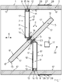
- Fig. 1
- eine erfindungsgemäße Absperrvorrichtung mit einem in einer Zwischenstellung befindlichen Klappenblatt,
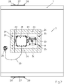
- Fig. 2
- eine Außenansicht auf den Gegenstand nach
Fig. 1 und - Fig. 3
- das Detail "Z" aus
Fig. 1 , wobei der Bereich der rechten Ecke des Seitenabschnittes des in der oberen Hälfte des Gehäuses angeordneten Anschlages und der Bereich der linken Ecke des Seitenabschnittes des in der unteren Hälfte des Gehäuses angeordneten Anschlages nicht dargestellt sind. - In allen Figuren werden für gleiche bzw. gleichartige Bauteile übereinstimmende Bezugszeichen verwendet.
- Die Figuren zeigen eine Absperrvorrichtung mit einem eine umlaufende Gehäusewandung 1 aufweisenden Gehäuse 2. In dem dargestellten Ausführungsbeispiel weist das Gehäuse 2 eine viereckige Querschnittsfläche auf. Damit besteht die Gehäusewandung 1 aus insgesamt vier Gehäusewandungsabschnitten, die beispielsweise mittels nicht dargestellter Schrauben gegeneinander fixiert sind. In dem Gehäuse 2 ist ein, um eine Schwenkachse 3 in Richtung des Pfeils 4 schwenkbar gelagertes Klappenblatt 5 vorgesehen. Die Schwenkachse 3 ist bezogen auf das Klappenblatt 5 mittig angeordnet. Im Bereich der Schwenkachse 3 ist zwischen dem Klappenblatt 5 und der Gehäusewandung 1 eine nicht dargestellte Dichtung vorgesehen. Mittels einer Schraube 16 ist das Klappenblatt 5 drehfest gegenüber der Schwenkachse 3 befestigt. In dem dargestellten Ausführungsbeispiel durchfasst die Schraube 16 die Schwenkachse 3.
- In dem dargestellten Ausführungsbeispiel ist die Absperrvorrichtung als Brandschutzklappe ausgebildet. Sowohl die Gehäusewandung 1 des Gehäuses 2 als auch das Klappenblatt 5 bestehen dabei aus Kalzium-Silikat-Platten.
- Wie nachstehend noch erläutert werden wird, sind sämtliche Bereiche und Bestandteile der Absperrvorrichtung, die mit dem in dem Gehäuse 2 strömenden gasförmigen Medium in Kontakt sind, durch eine Beschichtung 17 gegen schädigende chemische Reaktionen und/oder gegen schädigende Korrosionen geschützt. Damit eignet sich die Absperrvorrichtung auch zur Beeinflussung der Strömung chemisch aggressiver gasförmiger Medien und kann insoweit beispielsweise in einer Abluftleitung eines Labors oder eines Laborabzuges eingesetzt werden. Auch eine Verwendung beispielsweise in Lüftungsleitungen von gewerblichen Küchen, beispielsweise als Küchenabluftklappe, ist selbstverständlich möglich.
- In Strömungsrichtung 6 gesehen sowohl vor als auch hinter der Schwenkachse 3 ist jeweils ein Anschlag 7 auf der Innenseite des Gehäuses 2 vorgesehen. Die Anschläge 7 mit ihrer beidseitig aufgebrachten Beschichtung 17 sind in Strömungsrichtung 6 gesehen etwa um die Dicke des Klappenblattes 5, das allseitig die Beschichtung 17 aufweist, versetzt zueinander und auf gegenüberliegenden Seiten des Gehäuses 2 angeordnet und mittels von der Beschichtung 17 verdeckter Schrauben an der angrenzenden Gehäusewandung 1 befestigt.
- Jeder Anschlag 7 ist in etwa U-förmig ausgebildet und besteht aus einem Basisabschnitt 8, der parallel zur Schwenkachse 3 angeordnet ist. An beiden Enden jedes Basisabschnitts 8 grenzt jeweils ein Seitenabschnitt 9 an. Die Länge jedes Seitenabschnitts 9 ist so abgestimmt, dass in der Offenstellung das Klappenblatt 5 parallel zur Strömungsrichtung 6 ausgerichtet ist. In dieser Stellung kann das Klappenblatt 5 alle vier freien Enden der Seitenabschnitte 9 berühren. Bei einer solchen Ausgestaltung definieren die vier Enden der Seitenabschnitte 9 die Offenstellung des Klappenblattes 5.
- Wie
Fig. 1 zu entnehmen ist, weist jeder Anschlag 7 auf der Seite, die dem Klappenblatt 5 in seiner Schließstellung zugewandt ist, eine Ausnehmung 10 auf, die in dem dargestellten Ausführungsbeispiel einen viereckigen Querschnitt aufweist. Jede Ausnehmung 10 wird durch einen vorspringenden Bereich 11 des Anschlages 7 sowie durch die angrenzende Gehäusewandung 1 gebildet. - In der Ausnehmung 10 ist eine die Ausnehmung 10 vollständig ausfüllende Dichtung 12 vorgesehen, die zudem aus der Ausnehmung 10 herausragt und damit gegenüber dem Anschlag 7 hervorsteht. Jede Ausnehmung 10 erstreckt sich über die komplette Länge des Basisabschnittes 8 und der beiden Seitenabschnitte 9 des betreffenden Anschlages 7. Auch die mit dem strömenden Medium in Kontakt kommenden Bereiche der Dichtung 12 sind mit der Beschichtung 17 versehen.
- In der Offenstellung liegt das Klappenblatt 5 an einem Anschlag 18 an, der mittels nicht erkennbarer Schrauben an der Gehäusewandung 1 befestigt ist. In dem dargestellten Ausführungsbeispiel sind auch die mit dem strömenden Medium in Kontakt kommenden Oberflächen des Anschlags 18 mit der Beschichtung 17 versehen.
- Die Beschichtung 17 überzieht in dem dargestellten Ausführungsbeispiel sämtliche Oberflächen der Bereiche/Bestandteile der Absperrvorrichtung, die mit dem in dem Gehäuse 2 strömenden Medium in Kontakt sind. Damit ist beispielsweise auch die Innenseite der Gehäusewandung 1 mit der Beschichtung 17 versehen.
- In dem Klappenblatt 5 ist in dem mit der Dichtung 12 in der Schließstellung zusammenwirkenden Teilbereich eine Aussparung 13 vorgesehen, die in der Schließstellung des Klappenblattes 5 den gegenüber dem Anschlag 7 hervorstehenden Teil der Dichtung 12 in dem dargestellten Fall vollständig aufnimmt. Bei einer solchen Ausgestaltung berührt das Klappenblatt 5 in seiner Schließstellung den vorspringenden Bereich 11 des Anschlages 7. Sollte in der Schließstellung des Klappenblattes 5 zwischen dem vorspringenden Bereich 11 des Anschlages 7 und dem Klappenblatt 5 ein Spalt verbleiben, ist dieser zumindest auf ein Minimum reduziert.
- In dem dargestellten Ausführungsbeispiel bilden die in dem Anschlag 7 vorgesehene Ausnehmung 10 und die in dem Klappenblatt 5 korrespondierende Aussparung 13 eine rechteckige Gesamtquerschnittsfläche. Die Querschnittsfläche der Dichtung 12, die beispielsweise aus einem nicht brennbaren mineralfaserhaltigen, insbesondere als Mineralfaserschaumstoff ausgebildeten, Material besteht, weist eine korrespondierende Kontur, d. h. ebenfalls einen rechteckigen Querschnitt, auf. Die Dichtung 12 ist vorzugsweise vollumfänglich, d. h. an allen vier Seiten, mit einer nicht brennbaren, insbesondere als beschichtetes Glasgewebe ausgebildeten, Schicht abgedeckt. Diese Schicht besteht beispielsweise aus einem Material, das einen Schmelzpunkt von mehr als 1000° Celsius, vorzugsweise mehr als 1400° Celsius, hat. Es kann sich beispielsweise um ein Vlies aus Erdalkalisilikatwolle handeln. Dies ist eine Hochtemperatur-Glaswolle.
- Wie
Fig. 1 zu entnehmen ist, ist in jedem der vier Gehäusewandungsabschnitte zumindest eine durch Fräsen erzeugte Montagefläche 14 mit zumindest einer Anlagekante 15 eingebracht. Im montierten Zustand liegt die Seitenkante des Anschlages 7, die das Klappenblatt 5 in ihrer Schließstellung zugewandt ist, an der Anlagekante 15 an. Die Anlagekante 15 erlaubt eine optimale Montage und ein einfaches Ausrichten des Anschlages 7 gegenüber dem Klappenblatt 5. - In der Schließstellung verbleibt zwischen der Stirnfläche des Klappenblattes 5 und der Innenseite der Gehäusewandung 1 ein geringfügiger Spalt. Dieser Spalt ist erforderlich, um eine Rotation des Klappenblattes 5 in dem Gehäuse 2 zu ermöglichen.
-
Fig. 2 zeigt eine Außenseite der Absperrvorrichtung. So ist auf dieser Außenseite eine Antriebseinrichtung 34 vorgesehen, die mittels Schrauben 19 an der Außenseite des Gehäuses 2 befestigt ist. Die Antriebseinrichtung 34 wirkt mit der Schwenkachse 3 zusammen. Um die Position des Klappenblattes 5 von außen erkennen zu können, ist ein Stellungsanzeiger 20 vorgesehen. - Zur Steuerung der Antriebseinrichtung 34 ist ein Modul 21 vorgesehen, das mittels Schrauben 22 an einer an dem Gehäuse 2 befestigten Konsole 23 montiert ist. Zum Schutz der Antriebseinrichtung 34 und des Moduls 21 ist eine viereckige Kapselung 24, die mit Schrauben 25 an dem Gehäuse 2 befestigt ist, vorgesehen. Die Kapselung 24 besteht aus fünf Kalzium-Silikat-Platten und bildet mit der angrenzenden Gehäusewandung 1 einen geschlossen Raum, in dem die Antriebseinrichtung 34 und das Modul 21 angeordnet sind.
- Außerhalb der Kapselung 24 ist auf der Außenseite des Gehäuses 2 ein thermisches Auslöseelement 26 mit einem Detektionsbereich 32 vorgesehen. Wie in
Fig. 1 dargestellt ist, durchgreift der Detektionsbereich 32 die Gehäusewandung 1 und ragt insoweit in das Gehäuse 2 hinein. Das Auslöseelement 26 ist über ein Kabel 33 mit der Antriebseinrichtung 34 und dem Modul 21 verbunden. Für Wartungszwecke ist in zwei gegenüberliegenden Gehäusewandungsabschnitten des Gehäuses 2 jeweils ein Revisionsdeckel 27 vorgesehen, der mittels Schrauben 28 an dem jeweiligen Gehäusewandungsabschnitt befestigt ist. - In
Fig. 3 ist das Detail "Z" ausFig. 1 dargestellt. WieFig. 3 zu entnehmen ist, weist das Klappenblatt 5 eine durchgehende Ausnehmung auf, durch die die Schwenkachse 3 geführt ist. Zur drehfesten Fixierung des Klappenblattes 5 gegenüber der Schwenkachse 3 ist die Schraube 16 vorgesehen. Dabei ist in beiden Oberflächen des Klappenblattes 5 beidseits der durchgehenden Ausnehmung, durch die die Schwenkachse 3 geführt ist, jeweils eine Fräsung 35 vorgesehen. Die eine Fräsung 35 ist so tief, dass sie eine Platte 36 und den Kopf der Schraube 16 aufnimmt, während die gegenüberliegende Fräsung 35 eine Platte 29 aufnimmt. In der Platte 29 ist ein Innengwinde, in das die Schraube 16 hineingedreht ist, vorgesehen. Die Platten 36, 29 sind aus Metall und dienen der Verteilung von Kräften. - Jede Fräsung 35 ist mit jeweils einer Abdeckung 30 abgedeckt, wobei jede Abdeckung 30 mittels Schrauben 31 an dem Klappenblatt 5 befestigt ist. Jede Abdeckung 30 dient als thermischer Schutz der darunter befindlichen Befestigung in Form der Schraube 16. Die Abdeckungen 30 können beispielsweise aus Kalzium-Silikat-Platten bestehen. Wie
Fig. 3 zu entnehmen ist, zieht sich die Beschichtung 17 auch über die Abdeckungen 30, so dass das Klappenblatt 5 komplett beschichtet ist.
Claims (17)
- Absperrvorrichtung für den Einsatz in einer Luftleitung einer raumlufttechnischen Anlage oder einer maschinellen Entrauchungsanlage, wobei die Absperrvorrichtung ein, vorzugsweise einen viereckigen Querschnitt aufweisendes, von einem gasförmigen Medium durchströmtes Gehäuse (2) mit einer Gehäusewandung (1) und ein in dem Gehäuse (2) um eine Schwenkachse (3) herum schwenkbar gelagertes Klappenblatt (5) umfasst, dadurch gekennzeichnet, dass für eine Verwendung der Absperrvorrichtung in Verbindung mit einem chemisch aggressiven gasförmigen Medium zumindest sämtliche Bereiche der Absperrvorrichtung, die mit dem in dem Gehäuse (2) strömenden Medium in Kontakt sind, gegen schädigende chemische Reaktionen mit diesem Medium oder aufgrund dieses Mediums beständig ausgebildet sind, wobei die Beständigkeit entweder durch das Material der mit dem strömenden Medium in Kontakt kommenden Bereiche selbst oder durch eine auf die mit dem strömenden Medium in Kontakt kommenden Bereiche aufgebrachte Beschichtung (17) gebildet ist.
- Absperrvorrichtung nach dem vorhergehenden Anspruch, dadurch gekennzeichnet, dass als Beschichtung (17) eine zwei- oder mehr-komponentige Epoxidharzbeschichtung vorgesehen ist.
- Absperrvorrichtung nach dem vorhergehenden Anspruch, dadurch gekennzeichnet, dass die Beschichtung (17) im ausgehärteten Zustand lösungsmittelfrei ist.
- Absperrvorrichtung nach einem der beiden vorhergehenden Ansprüche, dadurch gekennzeichnet, dass die Beschichtung (17) keramikverstärkt ist.
- Absperrvorrichtung nach einem der vorhergehenden Ansprüche, dadurch gekennzeichnet, dass die Beschichtung (17) aufsprühbar ist.
- Absperrvorrichtung nach einem der Ansprüche 1 bis 4, dadurch gekennzeichnet, dass die Beschichtung (17) mechanisch auftragbar ist.
- Absperrvorrichtung nach einem der vorhergehenden Ansprüche, dadurch gekennzeichnet, dass zwischen dem jeweiligen Bereich und der Beschichtung (17) eine Grundierung vorgesehen ist.
- Absperrvorrichtung nach einem der vorhergehenden Ansprüche, dadurch gekennzeichnet, dass zumindest ein Teilbereich der Gehäusewandung (1), vorzugsweise die komplette Gehäusewandung (1), aus zumindest einer Brandschutzbauplatte oder zumindest einer zementgebundenen Kalzium-Silikat-Platte ausgebildet ist.
- Absperrvorrichtung nach einem der vorhergehenden Ansprüche, dadurch gekennzeichnet, dass das Klappenblatt (5) aus zumindest einer Brandschutzbauplatte oder einer zementgebundenen Kalzium-Silikat-Platte ausgebildet ist.
- Absperrvorrichtung nach einem der vorhergehenden Ansprüche, dadurch gekennzeichnet, dass die Absperrvorrichtung als Entrauchungsklappe ausgebildet ist.
- Absperrvorrichtung nach einem der vorhergehenden Ansprüche, dadurch gekennzeichnet, dass die Absperrvorrichtung als Brandschutzklappe ausgebildet ist.
- Absperrvorrichtung nach dem vorhergehenden Anspruch, dadurch gekennzeichnet, dass das Klappenblatt (5) mittels einer Fixiereinrichtung gegen eine Rückstellkraft in seiner Offenstellung fixierbar ist und aus der fixierten Position, beispielsweise im Brandfall, nach Lösen der Fixiereinrichtung durch die Rückstellkraft in seine Schließstellung verschwenkbar ist.
- Absperrvorrichtung nach einem der vorhergehenden Ansprüche, dadurch gekennzeichnet, dass an das Klappenblatt (5) mittelbar oder unmittelbar eine Antriebseinrichtung (34) angreift.
- Absperrvorrichtung nach einem der vorhergehenden Ansprüche, dadurch gekennzeichnet, dass zur drehfesten Befestigung des Klappenblattes (5) gegenüber der Schwenkachse (3) zumindest eine, vorzugsweise die Schwenkachse (3) durchfassende, Schraube (16) vorgesehen ist.
- Absperrvorrichtung nach dem vorhergehenden Anspruch, dadurch gekennzeichnet, dass in zumindest einer Oberfläche des Klappenblattes (5) eine Aufnahme, vorzugsweise eine als Fräsung (35) ausgebildete Aufnahme, zur Aufnahme des im Bereich dieser Oberfläche des Klappenblattes (5) befindlichen Endes der Schraube (16) vorgesehen ist.
- Absperrvorrichtung nach dem vorhergehenden Anspruch, dadurch gekennzeichnet, dass zumindest eine Aufnahme mit einer, vorzugsweise mittels Schrauben (31) an dem Klappenblatt (5) befestigten, Abdeckung (30) verschlossen ist.
- Absperrvorrichtung nach einem der vorhergehenden Ansprüche, dadurch gekennzeichnet, dass die Absperrvorrichtung einen Energiespeicher umfasst.
Priority Applications (3)
| Application Number | Priority Date | Filing Date | Title |
|---|---|---|---|
| ES20165682T ES2984031T3 (es) | 2020-03-25 | 2020-03-25 | Dispositivo de cierre para su uso en un conducto de aire de un sistema de ventilación o en una instalación mecánica de extracción de humos |
| EP20165682.4A EP3885666B9 (de) | 2020-03-25 | 2020-03-25 | Absperrvorrichtung für den einsatz in einer luftleitung einer raumlufttechnischen anlage oder einer maschinellen entrauchungsanlage |
| PL20165682.4T PL3885666T3 (pl) | 2020-03-25 | 2020-03-25 | Urządzenie odcinające do zastosowania w przewodzie powietrznym instalacji wentylacyjnej lub mechanicznej instalacji oddymiającej |
Applications Claiming Priority (1)
| Application Number | Priority Date | Filing Date | Title |
|---|---|---|---|
| EP20165682.4A EP3885666B9 (de) | 2020-03-25 | 2020-03-25 | Absperrvorrichtung für den einsatz in einer luftleitung einer raumlufttechnischen anlage oder einer maschinellen entrauchungsanlage |
Publications (3)
| Publication Number | Publication Date |
|---|---|
| EP3885666A1 true EP3885666A1 (de) | 2021-09-29 |
| EP3885666B1 EP3885666B1 (de) | 2024-05-01 |
| EP3885666B9 EP3885666B9 (de) | 2024-07-10 |
Family
ID=70008391
Family Applications (1)
| Application Number | Title | Priority Date | Filing Date |
|---|---|---|---|
| EP20165682.4A Active EP3885666B9 (de) | 2020-03-25 | 2020-03-25 | Absperrvorrichtung für den einsatz in einer luftleitung einer raumlufttechnischen anlage oder einer maschinellen entrauchungsanlage |
Country Status (3)
| Country | Link |
|---|---|
| EP (1) | EP3885666B9 (de) |
| ES (1) | ES2984031T3 (de) |
| PL (1) | PL3885666T3 (de) |
Citations (4)
| Publication number | Priority date | Publication date | Assignee | Title |
|---|---|---|---|---|
| CH498996A (de) * | 1969-03-22 | 1970-11-15 | Deutsche Steinzeug | Brandschutzanordnung |
| FR2153480A1 (en) * | 1971-09-25 | 1973-05-04 | Trox Gmbh Geb | Fire break valves for ducts - combining use of pivoted gates and intumescent foams to seal the duct |
| FR2648891A1 (fr) * | 1989-06-23 | 1990-12-28 | Sari | Clapet, notamment a usage de clapet coupe-feu ou de clapet de desenfumage |
| DE202015102532U1 (de) * | 2015-05-18 | 2015-07-16 | Trox Gmbh | Absperrklappe für den Einsatz in einem Kanal einer raumlufttechnischen Anlage oder einer maschinellen Entrauchungsanlage |
-
2020
- 2020-03-25 EP EP20165682.4A patent/EP3885666B9/de active Active
- 2020-03-25 ES ES20165682T patent/ES2984031T3/es active Active
- 2020-03-25 PL PL20165682.4T patent/PL3885666T3/pl unknown
Patent Citations (4)
| Publication number | Priority date | Publication date | Assignee | Title |
|---|---|---|---|---|
| CH498996A (de) * | 1969-03-22 | 1970-11-15 | Deutsche Steinzeug | Brandschutzanordnung |
| FR2153480A1 (en) * | 1971-09-25 | 1973-05-04 | Trox Gmbh Geb | Fire break valves for ducts - combining use of pivoted gates and intumescent foams to seal the duct |
| FR2648891A1 (fr) * | 1989-06-23 | 1990-12-28 | Sari | Clapet, notamment a usage de clapet coupe-feu ou de clapet de desenfumage |
| DE202015102532U1 (de) * | 2015-05-18 | 2015-07-16 | Trox Gmbh | Absperrklappe für den Einsatz in einem Kanal einer raumlufttechnischen Anlage oder einer maschinellen Entrauchungsanlage |
Also Published As
| Publication number | Publication date |
|---|---|
| ES2984031T3 (es) | 2024-10-28 |
| EP3885666B1 (de) | 2024-05-01 |
| PL3885666T3 (pl) | 2024-09-02 |
| EP3885666B9 (de) | 2024-07-10 |
Similar Documents
| Publication | Publication Date | Title |
|---|---|---|
| EP3907838B1 (de) | Verteiler- und/oder brandschutzgehäuse, brandschutzeinrichtung und bausatz für ein verteiler- und/oder brandschutzgehäuse | |
| DE102013013209A1 (de) | Brandschutzeinrichtung II | |
| EP3885666B9 (de) | Absperrvorrichtung für den einsatz in einer luftleitung einer raumlufttechnischen anlage oder einer maschinellen entrauchungsanlage | |
| DE10134839A1 (de) | Einrichtung zum rauch- und feuerbeständigen Verschliessen eines Wand- oder Deckendurchbruchs | |
| EP2030651B1 (de) | Schutzvorrichtung für Lüftungskanäle | |
| EP2179768A1 (de) | Brandschutz-/Entrauchungseinrichtung | |
| EP0396785A1 (de) | Vorrichtung zum Absperren von Lüftungseinrichtungen | |
| DE2708109A1 (de) | Feuerschutzklappe fuer kanaele von klima- und belueftungsanlagen | |
| EP0003614B1 (de) | Feuerschutzabschluss zum Abdichten und Verschliessen von Öffnungen in Wänden und Decken | |
| DE10151584A1 (de) | Druckentlastungsklappe | |
| EP1762276B1 (de) | Auslöseeinrichtung zum Auslösen zumindest eines eine Leitung eines lufttechnischen Systems verschliessenden Absperrelementes | |
| DE202012104425U1 (de) | Einbauelement für eine Brandschutzklappe sowie Brandschutzklappe mit einem Einbauelement | |
| DE9300568U1 (de) | Brandschutzabsperrung für brennbare Rohrleitungen | |
| DE2262541A1 (de) | Absperrvorrichtung gegen feuer und rauch | |
| EP3101363B1 (de) | Absperrklappe für den einsatz in einem kanal einer raumlufttechnischen anlage oder einer maschinellen entrauchungsanlage | |
| DE1914738C3 (de) | Brandschutz Verschlußeinrichtung | |
| EP0454879B1 (de) | Entlüftungsgerät für eine Einzel-Entlüftungsanlage | |
| DE19652780A1 (de) | Wartungsfreie Vorrichtung zur rauch- und brandsicheren Abschottung einer Lüftungsrohrleitung | |
| DE10207212A1 (de) | Einrichtung zum Verschließen eines Wand- oder Deckendurchbruchs | |
| EP0300992A2 (de) | Brandschutzeinrichtung für Luftleitungen | |
| DE19700601A1 (de) | Verschlußeinrichtung für Strömungswege | |
| EP2772283A2 (de) | Brandschutzklappe zur Verhinderung von Brand- und Rauchübertragung in einem Rohrgehäuse | |
| EP0046481A1 (de) | Brandschutzklappe | |
| AT388870B (de) | Brandschutzeinrichtung fuer luftleitungen | |
| DE19649126C2 (de) | Absperrvorrichtung gegen eine Brandübertragung |
Legal Events
| Date | Code | Title | Description |
|---|---|---|---|
| PUAI | Public reference made under article 153(3) epc to a published international application that has entered the european phase |
Free format text: ORIGINAL CODE: 0009012 |
|
| STAA | Information on the status of an ep patent application or granted ep patent |
Free format text: STATUS: THE APPLICATION HAS BEEN PUBLISHED |
|
| AK | Designated contracting states |
Kind code of ref document: A1 Designated state(s): AL AT BE BG CH CY CZ DE DK EE ES FI FR GB GR HR HU IE IS IT LI LT LU LV MC MK MT NL NO PL PT RO RS SE SI SK SM TR |
|
| STAA | Information on the status of an ep patent application or granted ep patent |
Free format text: STATUS: REQUEST FOR EXAMINATION WAS MADE |
|
| 17P | Request for examination filed |
Effective date: 20220321 |
|
| RBV | Designated contracting states (corrected) |
Designated state(s): AL AT BE BG CH CY CZ DE DK EE ES FI FR GB GR HR HU IE IS IT LI LT LU LV MC MK MT NL NO PL PT RO RS SE SI SK SM TR |
|
| P01 | Opt-out of the competence of the unified patent court (upc) registered |
Effective date: 20230512 |
|
| GRAP | Despatch of communication of intention to grant a patent |
Free format text: ORIGINAL CODE: EPIDOSNIGR1 |
|
| STAA | Information on the status of an ep patent application or granted ep patent |
Free format text: STATUS: GRANT OF PATENT IS INTENDED |
|
| RIC1 | Information provided on ipc code assigned before grant |
Ipc: F24F 11/35 20180101ALI20230612BHEP Ipc: A62C 2/12 20060101ALI20230612BHEP Ipc: F24F 13/14 20060101AFI20230612BHEP |
|
| INTG | Intention to grant announced |
Effective date: 20230706 |
|
| GRAJ | Information related to disapproval of communication of intention to grant by the applicant or resumption of examination proceedings by the epo deleted |
Free format text: ORIGINAL CODE: EPIDOSDIGR1 |
|
| STAA | Information on the status of an ep patent application or granted ep patent |
Free format text: STATUS: REQUEST FOR EXAMINATION WAS MADE |
|
| GRAS | Grant fee paid |
Free format text: ORIGINAL CODE: EPIDOSNIGR3 |
|
| STAA | Information on the status of an ep patent application or granted ep patent |
Free format text: STATUS: GRANT OF PATENT IS INTENDED |
|
| GRAP | Despatch of communication of intention to grant a patent |
Free format text: ORIGINAL CODE: EPIDOSNIGR1 |
|
| INTC | Intention to grant announced (deleted) | ||
| INTG | Intention to grant announced |
Effective date: 20231128 |
|
| GRAA | (expected) grant |
Free format text: ORIGINAL CODE: 0009210 |
|
| STAA | Information on the status of an ep patent application or granted ep patent |
Free format text: STATUS: THE PATENT HAS BEEN GRANTED |
|
| AK | Designated contracting states |
Kind code of ref document: B1 Designated state(s): AL AT BE BG CH CY CZ DE DK EE ES FI FR GB GR HR HU IE IS IT LI LT LU LV MC MK MT NL NO PL PT RO RS SE SI SK SM TR |
|
| REG | Reference to a national code |
Ref country code: GB Ref legal event code: FG4D Free format text: NOT ENGLISH |
|
| REG | Reference to a national code |
Ref country code: CH Ref legal event code: EP |
|
| REG | Reference to a national code |
Ref country code: IE Ref legal event code: FG4D Free format text: LANGUAGE OF EP DOCUMENT: GERMAN |
|
| REG | Reference to a national code |
Ref country code: DE Ref legal event code: R096 Ref document number: 502020007806 Country of ref document: DE |
|
| REG | Reference to a national code |
Ref country code: CH Ref legal event code: PK Free format text: BERICHTIGUNG B9 |
|
| REG | Reference to a national code |
Ref country code: NL Ref legal event code: FP |
|
| REG | Reference to a national code |
Ref country code: LT Ref legal event code: MG9D |
|
| PG25 | Lapsed in a contracting state [announced via postgrant information from national office to epo] |
Ref country code: IS Free format text: LAPSE BECAUSE OF FAILURE TO SUBMIT A TRANSLATION OF THE DESCRIPTION OR TO PAY THE FEE WITHIN THE PRESCRIBED TIME-LIMIT Effective date: 20240901 |
|
| PG25 | Lapsed in a contracting state [announced via postgrant information from national office to epo] |
Ref country code: BG Free format text: LAPSE BECAUSE OF FAILURE TO SUBMIT A TRANSLATION OF THE DESCRIPTION OR TO PAY THE FEE WITHIN THE PRESCRIBED TIME-LIMIT Effective date: 20240501 |
|
| PG25 | Lapsed in a contracting state [announced via postgrant information from national office to epo] |
Ref country code: HR Free format text: LAPSE BECAUSE OF FAILURE TO SUBMIT A TRANSLATION OF THE DESCRIPTION OR TO PAY THE FEE WITHIN THE PRESCRIBED TIME-LIMIT Effective date: 20240501 Ref country code: FI Free format text: LAPSE BECAUSE OF FAILURE TO SUBMIT A TRANSLATION OF THE DESCRIPTION OR TO PAY THE FEE WITHIN THE PRESCRIBED TIME-LIMIT Effective date: 20240501 |
|
| PG25 | Lapsed in a contracting state [announced via postgrant information from national office to epo] |
Ref country code: GR Free format text: LAPSE BECAUSE OF FAILURE TO SUBMIT A TRANSLATION OF THE DESCRIPTION OR TO PAY THE FEE WITHIN THE PRESCRIBED TIME-LIMIT Effective date: 20240802 |
|
| PG25 | Lapsed in a contracting state [announced via postgrant information from national office to epo] |
Ref country code: PT Free format text: LAPSE BECAUSE OF FAILURE TO SUBMIT A TRANSLATION OF THE DESCRIPTION OR TO PAY THE FEE WITHIN THE PRESCRIBED TIME-LIMIT Effective date: 20240902 |
|
| REG | Reference to a national code |
Ref country code: ES Ref legal event code: FG2A Ref document number: 2984031 Country of ref document: ES Kind code of ref document: T3 Effective date: 20241028 |
|
| PG25 | Lapsed in a contracting state [announced via postgrant information from national office to epo] |
Ref country code: LV Free format text: LAPSE BECAUSE OF FAILURE TO SUBMIT A TRANSLATION OF THE DESCRIPTION OR TO PAY THE FEE WITHIN THE PRESCRIBED TIME-LIMIT Effective date: 20240501 |
|
| PG25 | Lapsed in a contracting state [announced via postgrant information from national office to epo] |
Ref country code: PT Free format text: LAPSE BECAUSE OF FAILURE TO SUBMIT A TRANSLATION OF THE DESCRIPTION OR TO PAY THE FEE WITHIN THE PRESCRIBED TIME-LIMIT Effective date: 20240902 Ref country code: LV Free format text: LAPSE BECAUSE OF FAILURE TO SUBMIT A TRANSLATION OF THE DESCRIPTION OR TO PAY THE FEE WITHIN THE PRESCRIBED TIME-LIMIT Effective date: 20240501 Ref country code: IS Free format text: LAPSE BECAUSE OF FAILURE TO SUBMIT A TRANSLATION OF THE DESCRIPTION OR TO PAY THE FEE WITHIN THE PRESCRIBED TIME-LIMIT Effective date: 20240901 Ref country code: HR Free format text: LAPSE BECAUSE OF FAILURE TO SUBMIT A TRANSLATION OF THE DESCRIPTION OR TO PAY THE FEE WITHIN THE PRESCRIBED TIME-LIMIT Effective date: 20240501 Ref country code: GR Free format text: LAPSE BECAUSE OF FAILURE TO SUBMIT A TRANSLATION OF THE DESCRIPTION OR TO PAY THE FEE WITHIN THE PRESCRIBED TIME-LIMIT Effective date: 20240802 Ref country code: FI Free format text: LAPSE BECAUSE OF FAILURE TO SUBMIT A TRANSLATION OF THE DESCRIPTION OR TO PAY THE FEE WITHIN THE PRESCRIBED TIME-LIMIT Effective date: 20240501 Ref country code: BG Free format text: LAPSE BECAUSE OF FAILURE TO SUBMIT A TRANSLATION OF THE DESCRIPTION OR TO PAY THE FEE WITHIN THE PRESCRIBED TIME-LIMIT Effective date: 20240501 Ref country code: RS Free format text: LAPSE BECAUSE OF FAILURE TO SUBMIT A TRANSLATION OF THE DESCRIPTION OR TO PAY THE FEE WITHIN THE PRESCRIBED TIME-LIMIT Effective date: 20240801 |
|
| PG25 | Lapsed in a contracting state [announced via postgrant information from national office to epo] |
Ref country code: DK Free format text: LAPSE BECAUSE OF FAILURE TO SUBMIT A TRANSLATION OF THE DESCRIPTION OR TO PAY THE FEE WITHIN THE PRESCRIBED TIME-LIMIT Effective date: 20240501 |
|
| PG25 | Lapsed in a contracting state [announced via postgrant information from national office to epo] |
Ref country code: EE Free format text: LAPSE BECAUSE OF FAILURE TO SUBMIT A TRANSLATION OF THE DESCRIPTION OR TO PAY THE FEE WITHIN THE PRESCRIBED TIME-LIMIT Effective date: 20240501 |
|
| PG25 | Lapsed in a contracting state [announced via postgrant information from national office to epo] |
Ref country code: CZ Free format text: LAPSE BECAUSE OF FAILURE TO SUBMIT A TRANSLATION OF THE DESCRIPTION OR TO PAY THE FEE WITHIN THE PRESCRIBED TIME-LIMIT Effective date: 20240501 |
|
| PG25 | Lapsed in a contracting state [announced via postgrant information from national office to epo] |
Ref country code: SK Free format text: LAPSE BECAUSE OF FAILURE TO SUBMIT A TRANSLATION OF THE DESCRIPTION OR TO PAY THE FEE WITHIN THE PRESCRIBED TIME-LIMIT Effective date: 20240501 Ref country code: RO Free format text: LAPSE BECAUSE OF FAILURE TO SUBMIT A TRANSLATION OF THE DESCRIPTION OR TO PAY THE FEE WITHIN THE PRESCRIBED TIME-LIMIT Effective date: 20240501 |
|
| PG25 | Lapsed in a contracting state [announced via postgrant information from national office to epo] |
Ref country code: SM Free format text: LAPSE BECAUSE OF FAILURE TO SUBMIT A TRANSLATION OF THE DESCRIPTION OR TO PAY THE FEE WITHIN THE PRESCRIBED TIME-LIMIT Effective date: 20240501 |
|
| PG25 | Lapsed in a contracting state [announced via postgrant information from national office to epo] |
Ref country code: SM Free format text: LAPSE BECAUSE OF FAILURE TO SUBMIT A TRANSLATION OF THE DESCRIPTION OR TO PAY THE FEE WITHIN THE PRESCRIBED TIME-LIMIT Effective date: 20240501 Ref country code: SK Free format text: LAPSE BECAUSE OF FAILURE TO SUBMIT A TRANSLATION OF THE DESCRIPTION OR TO PAY THE FEE WITHIN THE PRESCRIBED TIME-LIMIT Effective date: 20240501 Ref country code: RO Free format text: LAPSE BECAUSE OF FAILURE TO SUBMIT A TRANSLATION OF THE DESCRIPTION OR TO PAY THE FEE WITHIN THE PRESCRIBED TIME-LIMIT Effective date: 20240501 Ref country code: EE Free format text: LAPSE BECAUSE OF FAILURE TO SUBMIT A TRANSLATION OF THE DESCRIPTION OR TO PAY THE FEE WITHIN THE PRESCRIBED TIME-LIMIT Effective date: 20240501 Ref country code: DK Free format text: LAPSE BECAUSE OF FAILURE TO SUBMIT A TRANSLATION OF THE DESCRIPTION OR TO PAY THE FEE WITHIN THE PRESCRIBED TIME-LIMIT Effective date: 20240501 Ref country code: CZ Free format text: LAPSE BECAUSE OF FAILURE TO SUBMIT A TRANSLATION OF THE DESCRIPTION OR TO PAY THE FEE WITHIN THE PRESCRIBED TIME-LIMIT Effective date: 20240501 |
|
| REG | Reference to a national code |
Ref country code: DE Ref legal event code: R097 Ref document number: 502020007806 Country of ref document: DE |
|
| PG25 | Lapsed in a contracting state [announced via postgrant information from national office to epo] |
Ref country code: IT Free format text: LAPSE BECAUSE OF FAILURE TO SUBMIT A TRANSLATION OF THE DESCRIPTION OR TO PAY THE FEE WITHIN THE PRESCRIBED TIME-LIMIT Effective date: 20240501 |
|
| PLBE | No opposition filed within time limit |
Free format text: ORIGINAL CODE: 0009261 |
|
| STAA | Information on the status of an ep patent application or granted ep patent |
Free format text: STATUS: NO OPPOSITION FILED WITHIN TIME LIMIT |
|
| 26N | No opposition filed |
Effective date: 20250204 |
|
| REG | Reference to a national code |
Ref country code: DE Ref legal event code: R081 Ref document number: 502020007806 Country of ref document: DE Owner name: TROX SE, DE Free format text: FORMER OWNER: TROX GMBH, 47506 NEUKIRCHEN-VLUYN, DE |
|
| PG25 | Lapsed in a contracting state [announced via postgrant information from national office to epo] |
Ref country code: SI Free format text: LAPSE BECAUSE OF FAILURE TO SUBMIT A TRANSLATION OF THE DESCRIPTION OR TO PAY THE FEE WITHIN THE PRESCRIBED TIME-LIMIT Effective date: 20240501 |
|
| PGFP | Annual fee paid to national office [announced via postgrant information from national office to epo] |
Ref country code: ES Payment date: 20250416 Year of fee payment: 6 |
|
| PGFP | Annual fee paid to national office [announced via postgrant information from national office to epo] |
Ref country code: CH Payment date: 20250401 Year of fee payment: 6 |
|
| PG25 | Lapsed in a contracting state [announced via postgrant information from national office to epo] |
Ref country code: SE Free format text: LAPSE BECAUSE OF FAILURE TO SUBMIT A TRANSLATION OF THE DESCRIPTION OR TO PAY THE FEE WITHIN THE PRESCRIBED TIME-LIMIT Effective date: 20240501 |
|
| PG25 | Lapsed in a contracting state [announced via postgrant information from national office to epo] |
Ref country code: MC Free format text: LAPSE BECAUSE OF FAILURE TO SUBMIT A TRANSLATION OF THE DESCRIPTION OR TO PAY THE FEE WITHIN THE PRESCRIBED TIME-LIMIT Effective date: 20240501 |
|
| PG25 | Lapsed in a contracting state [announced via postgrant information from national office to epo] |
Ref country code: LU Free format text: LAPSE BECAUSE OF NON-PAYMENT OF DUE FEES Effective date: 20250325 |
|
| PG25 | Lapsed in a contracting state [announced via postgrant information from national office to epo] |
Ref country code: IE Free format text: LAPSE BECAUSE OF NON-PAYMENT OF DUE FEES Effective date: 20250325 |
|
| REG | Reference to a national code |
Ref country code: CH Ref legal event code: U11 Free format text: ST27 STATUS EVENT CODE: U-0-0-U10-U11 (AS PROVIDED BY THE NATIONAL OFFICE) Effective date: 20260401 |
|
| PGFP | Annual fee paid to national office [announced via postgrant information from national office to epo] |
Ref country code: GB Payment date: 20260317 Year of fee payment: 7 |
|
| PGFP | Annual fee paid to national office [announced via postgrant information from national office to epo] |
Ref country code: NO Payment date: 20260320 Year of fee payment: 7 Ref country code: DE Payment date: 20260305 Year of fee payment: 7 |
|
| PGFP | Annual fee paid to national office [announced via postgrant information from national office to epo] |
Ref country code: AT Payment date: 20260319 Year of fee payment: 7 |
|
| PGFP | Annual fee paid to national office [announced via postgrant information from national office to epo] |
Ref country code: BE Payment date: 20260323 Year of fee payment: 7 |
|
| PGFP | Annual fee paid to national office [announced via postgrant information from national office to epo] |
Ref country code: NL Payment date: 20260323 Year of fee payment: 7 |
|
| PGFP | Annual fee paid to national office [announced via postgrant information from national office to epo] |
Ref country code: FR Payment date: 20260325 Year of fee payment: 7 |
|
| PGFP | Annual fee paid to national office [announced via postgrant information from national office to epo] |
Ref country code: PL Payment date: 20260210 Year of fee payment: 7 |