EP3885752A1 - Dispositif et procédé d'analyse structurelle aux rayons x sur monocristal, et porte-échantillon associé - Google Patents
Dispositif et procédé d'analyse structurelle aux rayons x sur monocristal, et porte-échantillon associé Download PDFInfo
- Publication number
- EP3885752A1 EP3885752A1 EP19887578.3A EP19887578A EP3885752A1 EP 3885752 A1 EP3885752 A1 EP 3885752A1 EP 19887578 A EP19887578 A EP 19887578A EP 3885752 A1 EP3885752 A1 EP 3885752A1
- Authority
- EP
- European Patent Office
- Prior art keywords
- sample
- crystal
- sample holder
- ray
- structure analysis
- Prior art date
- Legal status (The legal status is an assumption and is not a legal conclusion. Google has not performed a legal analysis and makes no representation as to the accuracy of the status listed.)
- Withdrawn
Links
Images



Classifications
-
- G—PHYSICS
- G01—MEASURING; TESTING
- G01N—INVESTIGATING OR ANALYSING MATERIALS BY DETERMINING THEIR CHEMICAL OR PHYSICAL PROPERTIES
- G01N23/00—Investigating or analysing materials by the use of wave or particle radiation, e.g. X-rays or neutrons, not covered by groups G01N3/00 – G01N17/00, G01N21/00 or G01N22/00
- G01N23/20—Investigating or analysing materials by the use of wave or particle radiation, e.g. X-rays or neutrons, not covered by groups G01N3/00 – G01N17/00, G01N21/00 or G01N22/00 by using diffraction of the radiation by the materials, e.g. for investigating crystal structure; by using scattering of the radiation by the materials, e.g. for investigating non-crystalline materials; by using reflection of the radiation by the materials
- G01N23/20008—Constructional details of analysers, e.g. characterised by X-ray source, detector or optical system; Accessories therefor; Preparing specimens therefor
- G01N23/20025—Sample holders or supports therefor
-
- G—PHYSICS
- G01—MEASURING; TESTING
- G01N—INVESTIGATING OR ANALYSING MATERIALS BY DETERMINING THEIR CHEMICAL OR PHYSICAL PROPERTIES
- G01N23/00—Investigating or analysing materials by the use of wave or particle radiation, e.g. X-rays or neutrons, not covered by groups G01N3/00 – G01N17/00, G01N21/00 or G01N22/00
- G01N23/20—Investigating or analysing materials by the use of wave or particle radiation, e.g. X-rays or neutrons, not covered by groups G01N3/00 – G01N17/00, G01N21/00 or G01N22/00 by using diffraction of the radiation by the materials, e.g. for investigating crystal structure; by using scattering of the radiation by the materials, e.g. for investigating non-crystalline materials; by using reflection of the radiation by the materials
- G01N23/20008—Constructional details of analysers, e.g. characterised by X-ray source, detector or optical system; Accessories therefor; Preparing specimens therefor
- G01N23/20016—Goniometers
-
- G—PHYSICS
- G01—MEASURING; TESTING
- G01N—INVESTIGATING OR ANALYSING MATERIALS BY DETERMINING THEIR CHEMICAL OR PHYSICAL PROPERTIES
- G01N23/00—Investigating or analysing materials by the use of wave or particle radiation, e.g. X-rays or neutrons, not covered by groups G01N3/00 – G01N17/00, G01N21/00 or G01N22/00
- G01N23/20—Investigating or analysing materials by the use of wave or particle radiation, e.g. X-rays or neutrons, not covered by groups G01N3/00 – G01N17/00, G01N21/00 or G01N22/00 by using diffraction of the radiation by the materials, e.g. for investigating crystal structure; by using scattering of the radiation by the materials, e.g. for investigating non-crystalline materials; by using reflection of the radiation by the materials
- G01N23/207—Diffractometry using detectors, e.g. using a probe in a central position and one or more displaceable detectors in circumferential positions
Definitions
- the present invention relates to a next-generation single-crystal X-ray structure analysis apparatus capable of analyzing a structure of a material by an aggregative microstructure such as its atomic or molecular arrangement, and an analysis method therefor; and relates specifically to a single-crystal X-ray structure analysis apparatus and a method that comprise tools for performing processing including preparation of a single-crystal sample as an analysis object, and a sample holder therefor.
- the materials are ordinarily synthesized and evaluated to determine the next research policy based on the foregoing.
- a search method of a material structure centering on the material structure analysis capable of efficiently performing the structure analysis, and an X-ray structure analysis used therein are indispensable for efficiently searching the material structure that realizes the function/physical property of an object material.
- the present invention has been achieved in view of problems in the above-described conventional technique, and the objective is, specifically, to enable quickly, surely and easily performing single-crystal X-ray structure analysis without conventionally fine and precise operations for which rapidness is required being accompanied, with a very small and fragile crystalline sponge, even if not having specialized knowledge of X-ray structure analysis, in other words, the objective is to provide a high-yield, efficient, very versatile and user-friendly single-crystal X-ray structure analysis apparatus and a method therefor; and further to provide a sample holder as a tool therefor.
- a series of operations including soaking a sample in a very small and fragile crystalline sponge, followed by installing it in a device can be quickly, surely and safely carried out by using a newly proposed sample holder, without accompanying conventionally precise and fine operations for which rapidness is also required; in other words, provided is a high-yield, efficient, very versatile and user-friendly single-crystal X-ray structure analysis apparatus. Further provide are an analysis method therefor and a sample holder as a tool therefor. Thus, it becomes possible to make a single-crystal X-ray structure analysis with a crystalline sponge easily usable, and to widely spread it.
- FIG. 1 shows the entire appearance configuration of a single-crystal X-ray structure analysis apparatus provided with a single-crystal X-ray diffractometer according to one embodiment of the present invention, and as is clear from the figure, the single-crystal X-ray structure analysis apparatus 1 comprises a base stand 4 in which a cooling device and an X-ray generation power supply unit are stored, and an X-ray protection cover 6 placed on the base stand 4.
- the X-ray protection cover 6 is provided with a casing 7 for surrounding the single-crystal X-ray diffractometer 9, a door 8 provided in front of the casing 7, and so forth.
- the door 8 provided in front of the casing 7 is openable, and in this open state, various operations can be performed for the internal single-crystal X-ray diffractometer 9.
- the present embodiment as shown in the figure is directed to the single-crystal X-ray structure analysis apparatus 1 provided with the single-crystal X-ray diffractometer 9 for performing a structure analysis of a material using the crystalline sponge mentioned below.
- the single-crystal X-ray diffractometer 9 comprises an X-ray tube 11 and a goniometer 12, as shown in FIG. 2 as well.
- the X-ray tube 11 comprises a filament, a target (referred to also as “anticathode”) arranged so as to be opposed to the filament, and a casing for airtightly storing them, though not shown in the figure herein.
- This filament subjected to current applied by the X-ray generation power supply unit stored in the base stand 4 of FIG. 1 generates heat to emit thermal electrons. Further, a high voltage is applied between the filament and the target by the X-ray generation power supply unit, and the thermal electrons emitted from the filament are accelerated by the high voltage, and collide with the target.
- the X-ray tube 11 comprising a microfocus tube and an optical element such as a multilayer focusing mirror or the like enables irradiation with higher brightness beam, and can also be selected from a radiation source such as Cu, Mo, Ag or the like.
- the filament, the target arranged so as to be opposed to the filament, and the casing for airtightly storing them serve as an X-ray source
- a configuration for X-ray irradiation comprising the microfocus tube and the optical element such as the multilayer focusing mirror or the like serves as an X-ray irradiation section.
- the goniometer 12 supporting a sample S to be analyzed comprises a ⁇ rotation table 16 that is rotatable with a sample axis line ⁇ passing through an X-ray incident point of the sample S as a center, and a 2 ⁇ rotation table 17 that is arranged around the ⁇ rotation table 16 and is rotatable with the sample axis line ⁇ as a center.
- the sample S is soaked inside a crystalline sponge previously attached to a part of the sample holder 250 mentioned below.
- Driving devices (not shown in the figure) for driving the above-described ⁇ rotation table 16 and 2 ⁇ rotation table 17 are stored inside a base 18 of the goniometer 12, and the ⁇ rotation table 16 is driven by these driving devices to be intermittently or continuously rotated at a predetermined angular speed so as to make a so-called ⁇ rotation. Further, the 2 ⁇ rotation table 17 is driven by these driving devices to be intermittently or continuously rotated so as to make a so-called 2 ⁇ rotation.
- the above-described driving devices can be constituted from any structure, and for example, can be constituted from a power transmission structure comprising a worm and a worm wheel.
- An X-ray detector 22 is placed on a part of the outer periphery of the goniometer 12, and the X-ray detector 22 is constituted from for example, CCD type and CMOS type two-dimensional pixel detectors, a hybrid type pixel detector, or the like.
- an X-ray detection measurement section means a configuration in which X-rays diffracted or scattered by the sample are detected and measured, and comprises the X-ray detector 22 and a control section that controls the same.
- the single-crystal X-ray diffractometer 9 is constituted as described above, and thus the sample S is ⁇ -rotated with the sample axis line ⁇ as a center by the ⁇ rotation of the ⁇ rotation table 16 in the goniometer 12.
- X-rays generated from the X-ray focus inside the X-ray tube 11, that is directed to the sample S enter the sample S at a predetermined angle, and are diffracted/scattered. That is, the incident angle of X-rays entering the sample S changes depending on the ⁇ rotation of the sample S.
- diffraction X-rays are generated from the sample S.
- the diffraction X-rays are received by the X-ray detector 22 to measure an X-ray intensity thereof. From those described above, an angle of the X-ray detector 22 with respect to the incident X-rays, that is, an intensity of the diffraction X-rays corresponding to a diffraction angle is measured, and a crystal structure concerning the sample S and so forth are analyzed from this measurement result.
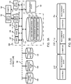
- FIG. 3A shows one example of the detail of an electrical internal configuration constituting a control section 110 in the above-described single-crystal X-ray structure analysis apparatus.
- the present invention is not limited to the following embodiments according to the present invention.
- This single-crystal X-ray structure analysis apparatus 1 includes the above-described internal configuration and further comprises a measurement device 102 for measuring a suitable material used as a sample; an input device 103 constituted from a keyboard, a mouse and so forth; an image display device 104 as display means; a printer 106 as means for printing and outputting the analysis result; CPU (Central Processing Unit) 107; RAM (Random Access Memory) 108; ROM (Read Only Memory) 109; a hard disk 111 as an external storage medium, and so forth. These elements are electrically connected mutually by a bus 112.
- the image display device 104 constituted from an image display unit such as a CRT display, a liquid-crystal display or the like displays an image on a screen in accordance with an image signal generated by an image control circuit 113.
- the image control circuit 113 generates the image signal based on image data input therein.
- the image data input in the image control circuit 113 is generated by an operation of every kind of calculation means, achieved by a computer comprising CPU 107, RAM 108, ROM 109, and the hard disk 111.
- An inkjet plotter, a dot printer, an inkjet printer, an electrostatic transfer printer, or any other printing unit having arbitrary structure is usable for the printer 106.
- the hard disk 111 can also be constituted from a magneto-optical disk, a semiconductor memory, or any other storage medium having arbitrary structure.
- Analysis application software 116 for managing the overall operation of the single-crystal X-ray structure analysis apparatus 1 measurement application software 117 for managing the operation of the measurement processing using the measurement device 102, and display application software 118 for managing the operation of the display processing using the image display device 104 are stored inside the hard disk 111. A predetermined function is achieved after reading these pieces of application software from the hard disk 111, as needed, to transfer them to RAM 108.
- This single-crystal X-ray structure analysis apparatus 1 further comprises for example, a database placed in a cloud area, the database for storing every kind of measurement results including measurement data obtained by the above-described measurement device 102.
- a database placed in a cloud area, the database for storing every kind of measurement results including measurement data obtained by the above-described measurement device 102.
- shown are an XRDS information database 120 that stores XRDS image data obtained by the above-described measurement device 102, and a microscope image database 130 that stores actually observed images obtained by the microscope, and further shown are for example, measurement results obtained via analysis performed with not X-rays but XRF, Raman ray or the like, and another analysis database 140 that stores physical property information.
- these databases are not necessarily stored inside the single-crystal X-ray structure analysis apparatus 1, and for example, they may be provided outside and be communicably connected mutually via a network 150 or the like.
- a method of storing individual measurement data inside an individual file is also taken into account as a file management method for storing a plurality of pieces of measurement data inside a data file, but according to the present embodiment, as shown in FIG. 3B , the plurality of pieces of measurement data are set to be continuously stored inside one data file.
- storage areas each in which "condition" is written are an area for storing every kind of information including device information and measurement conditions when obtaining the measurement data.
- measurement conditions (1) name of measurement object material, (2) type of measurement device, (3) measurement temperature range, (4) measurement start time, (5) measurement end time, (6) measurement angle range, (7) moving speed in scanning movement system, (8) scanning condition, (9) type of X-rays incident on sample, (10) whether or not to use attachments such as a sample high-temperature device, and so forth, are conceivable and every kind of other conditions is also conceivable.
- An XRDS (X-ray Diffraction and Scattering) pattern or an image is obtained by receiving/accumulating X-rays received on a flat plane that is a two-dimensional space of the X-ray detector 22 constituting the above-described measurement device 102 for each pixel arranged in a planar array, that constitutes the detector, and by measuring an intensity thereof.
- a pattern or an image on a two-dimensional space of r and ⁇ can be obtained by detecting the intensity of X-rays received via an integral, for each pixel of the X-ray detector 22.
- the XRDS pattern or the image on an observation space, that is obtained by diffraction and scattering of X-rays caused by an object material for irradiation of the X-rays reflects information of an electron density distribution in an actual space of the object material.
- the XRDS pattern being on the two-dimensional space of r and ⁇ does not directly represents symmetry in the actual space of the object material as a three-dimensional space. Accordingly, it is generally difficult to specify the (spatial) arrangement of atoms and molecules that constitute the material with only the existing XRDS image, and thus a specialized knowledge of X-ray structure analysis is required. Therefore, according to the present Example, automatization is achieved by adopting the above-described measurement application software.
- the single-crystal X-ray structure analysis apparatus 1 receives and manages every kind of measurement results including measurement data obtained by detecting X-rays diffracted or scattered by a sample with the X-ray detection measurement section while controlling a measurement processing operation using the measurement device 102. Further, the sample is subjected to structure analysis with a structure analysis section, based on every kind of measurement results including the measurement data obtained by detecting the X-rays diffracted or scattered by the sample.
- X-ray diffraction data measurement/processing software called “CrysAlis Pro” that is a platform for single-crystal structure analysis is installed to execute preliminary measurement, setting of measurement conditions, main measurement, data processing and so forth. Further, structure analysis and structure refinement are executed in parallel with X-ray diffraction data collection by installing an automatic structure analysis plug-in called "AutoChem”. Then, from space group determination to phase determination, construction and correction of molecular modelling, structure refinement, final reporting, and preparation of a CIF file are executed by a structure analysis program called "Olex 2 " as also shown in FIG. 6 .
- the single-crystal X-ray structure analysis has become widely applicable for those including a liquid compound that cannot be crystallized, a very small amount of a sample with several ng to several ⁇ g that is incapable of acquiring a sufficient amount to perform crystallization, or the like via development of a material called "crystalline sponge" as a very small and fragile porous complex crystal having a size of several 10 ⁇ m to several 100 ⁇ m, in whose inside countless pores each having a diameter of 0.5 to 1 nm are formed.
- a step of soaking a very small amount of a sample approximately several ng to several ⁇ g, separated by every kind of pretreatment (separation) devices in a framework of a very small and fragile crystalline sponge having an outer diameter of approximately 100 ⁇ m provided via immersion in a preserving solvent (carrier) such as cyclohexane or the like, inside a container.
- a preserving solvent such as cyclohexane or the like
- the present invention accomplished based on the above-described inventor's knowledge enables quickly, surely and easily performing an single-crystal X-ray structure analysis with a very small and fragile crystalline sponge by using a sample holder for the crystalline sponge (also referred to simply as a sample holder) as described below, in other words, achieves a high-yield, efficient, very versatile and user-friendly single-crystal X-ray structure analysis apparatus.
- the next-generation single-crystal X-ray structure analysis apparatus there is a large constraint that the very small and fragile crystalline sponge in which a very small amount of a sample S is soaked is prepared, and further, the sample S (crystalline sponge) needs to be taken up from a soaking container and precisely and quickly attached to a predetermined position at the tip portion of the goniometer 12 in a short and quick period of time in such an extent that the crystalline sponge is not broken due to drying , but specifically in order to achieve the very versatile and user-friendly apparatus, such operations needs to be made quickly and easily executable without requiring highly specialized knowledge as well as operation preciseness.
- the present invention described below in detail resolves such a problem, that is, provides an apparatus and a method for performing a high-yield, efficient, very versatile and user-friendly single-crystal X-ray structure analysis in a quick, sure and easy manner by anyone while also using a very small, fragile and difficultly handleable crystalline sponge; and further provides a sample holder as a tool therefor.
- FIG. 7A shows a tip portion of the goniometer 12 in an enlarged view, and this figure shows a state of that, the sample holder 250, being in an enlarged view as FIG. 7B , as a tool where the crystalline sponge 200 soaking a sample to be analyzed that is proposed according to the present invention is attached(mounted) to the goniometer head 121 as the tip portion of the goniometer 12 in advance.
- the sample holder 250 for example, can be attached/detached to/from the goniometer head 121 at the tip portion of the goniometer 12 by an attaching/positioning mechanism for which magnetic force or the like is used, and can be attached easily and accurately at an exact position by anyone.
- FIG. 8 shows a sectional view of the above-described sample holder 250.
- a pin (cylinder)-shaped sample holding part hereinafter, referred to simply as a holding part
- a holding part 252 (corresponding to the so-called goniometer head pin) is implanted vertically in the center of one surface (the lower surface in the figure) of the base part 251 of a disk or corn-shaped holder made of metal or the like attached to the goniometer head 121 ⁇ Refer to FIG.
- the crystalline sponge 200 in which the above-described sample to be analyzed is soaked is combinedly attached and fixed to the sample holder 250 beforehand at a predetermined position of the tip of the pin-shaped holding part 252.
- the positioning mechanism or the like such as a magnet that is not shown in the figure, or the like is provided on the other surface (upper surface in the figure) of the disk-shaped base part 251.
- the sample holder 250 is detachably attached to the tip portion of the goniometer 12 by this positioning mechanism.
- the so-called applicator 300 used with the sample holder 250 is shown as a handling (operating) tool for soaking the sample in the crystalline sponge 200 attached to the sample holder in advance.
- This applicator 300 is, for example, formed from a transparent or non-transparent member made of glass, a resin, metal or the like, in whose inside a storing space 301 for storing the above-described sample holder 250 is formed, and at whose upper portion the opening 302 through which the sample holder 250 is fitted and taken out is further formed.
- seal portions are provided at part of the opening 302 of the applicator 300 so as to be airtightly maintained from outside in a state of storing the sample holder 250 in the storing space 301 in an inside thereof.
- a pair of fine through holes 253, 253 for introducing a sample to be analyzed into the crystalline sponge 200 located inside (storing space 301) the applicator 300 are formed at the base part 251 of the sample holder 250.
- the fine holes 253, 253 exhibit preferable one example of a sample introduction structure, and other structures may be adopted.
- seal portions are provided for these fine holes 253, 253.
- the storing space 301 inside the applicator 300 is kept airtight even in a state where sample introduction tubes (hereinafter, referred to simply as introduction tubes) 254, 254 for introducing the sample into the crystalline sponge 200 are inserted in the fine holes 253, 253.
- introduction tubes hereinafter, referred to simply as introduction tubes
- the crystalline sponge 200 attached to the tip portion of the pin-shaped holding part 252 (corresponding to a goniometer head pin) constituting a part of the sample holding 250 can be safely and easily handled without damage or deviation from the sample holder 250. That is, the crystalline sponge 200 in which a very small amount of the sample is soaked can be safely, simply and easily prepared on the goniometer head 121 in a short and quick period of time in such an extent that no damage occurs due to drying, without any damage due to taking only it out from a soaking container unlike a conventional manner.
- the sample holder 250 with which soaking of the sample is completed is removed from the applicator 300, and is attached to the goniometer head 121 ⁇ Refer to FIG.7A ⁇ at the tip portion of the goniometer 12.
- the sample S soaked in the crystalline sponge 200 is easily, precisely and quickly arranged at a predetermined position inside the single-crystal X-ray diffractometer 9 without requiring highly specialized knowledge and precise operations.
- the sample holder 250 can be integrated (unitized) with the applicator 300 as a handling (operating) tool thereof, and further can be provided as a so-called set by preparing the required number of them for the analysis operation and storing them in a box-shaped case, as also shown in FIG. 9 .
- sample holder 250 and the applicator 300 may be provided as an integral one (unit) or as a set, as described above.
- FIG. 10 shows one Example according to the present invention given by conceptualizing the single-crystal X-ray structure analysis method using the sample holder 250.
- a very small amount of the sample is introduced into the sample holder 250 provided with the applicator 300 as an integral one (unit) to perform soaking required therein.
- the sample in the state where the sample holder 250 is stored inside the applicator 300, the sample can be soaked in the crystalline sponge 200 attached to the tip of the sample holder 250 by inserting a pair of the sample introduction tubes 254, 254 into a pair of the fine through holes 253, 253 (Refer to FIG. 8 ) formed in the sample holder 250.
- a very small amount of the sample S extracted by LC (liquid chromatography) 401, GC (gas chromatography) 402, and further, SCF (supercritical fluid chromatography) 403, CE (electrophoresis) 404 and so forth that constitute a pretreatment device 400 is supplied to a pair of the sample introduction tubes 254, 254 (Refer to FIG. 8 ) inserted in the fine holes 253, 253 of the sample holder 250 via the soaking device (soaking machine) 500 provided with every kind of a switching valve and a pressure adjustment device, that supplies a fluid under the necessary conditions (flow rate and pressure), and the sample is selectively introduced into the storing space 301 inside the applicator 300.
- the sample is sent to the sample introduction tube 254 on the supply side from a tube on the supply side, and is supplied to the sample holder 250 inside the applicator 300 from the tip portion of the sample introduction tube 254 on the supply side. Only the sample, or a solution in which the sample and the preserving solvent (carrier) are mixed is supplied by flowing inside the sample introduction tube 254 on the supply side. In this manner, a very small amount of the sample S introduced thereto comes into contact with the crystalline sponge 200 attached to the tip of the pin-shaped holding part 252 of the sample holder 250 inside the storing space 301 of the applicator 300, and the sample is soaked therein.
- examples of the electrophoresis device herein include various electrophoresis devices concerning capillary electrophoresis, isoelectric point electrophoresis, and so forth.
- the soaking device 500 in a state where the sample is injected, the excessive sample or a solution in which the sample and the preserving solvent (carrier) are mixed is discharged from the sample introduction tube 254 on the discharge side, after a predetermined time has elapsed.
- the unnecessary preserving solvent (carrier) or solution flows inside the sample introduction tube 254 on the discharge side, and is discharged. Accordingly, it is possible that no sample flows through the sample instruction tube 254 on the discharge side.
- gas or supercritical fluid as a carrier, the carrier containing the sample is discharged.
- the sample holder 250 with which the step of soaking is completed is removed from the applicator 300, and is precisely attached to a predetermined position inside the single-crystal X-ray diffractometer 9, that is, to the goniometer head 121 at the tip portion of the goniometer 12, for example, by using a positioning mechanism such as the above-described magnetic force or the like.
- the crystalline sponge 200 attached to a part (tip) of the pin-shaped holding part 252 of the sample holder 250 is to be arranged to the tip portion of the goniometer 12, that is, to a position where X-ray beam is focused and irradiated from the X-ray tube 11 after soaking the sample is completed .
- the sample S soaked in the crystalline sponge 200 is precisely arranged at an predetermined position inside the single-crystal X-ray diffractometer 9, and the intensity of X-rays diffracted from the sample S is subsequently measured by the X-ray detector 22 to analyze a crystal structure thereof, and so forth.
- the sample holder 250 by using the sample holder 250 according to the present invention, it becomes possible that a very small amount of sample is soaked in the crystalline sponge 200 in very small size, that is combinedly attached beforehand to the sample holder 250 in an easy and safe manner by anyone, and subsequently, the sample S is quickly and safely installed to the goniometer 12 as a precise position with high accuracy in a short period of time in such an extent that the crystalline sponge is not broken due to being dried.
- the present Example brings quick, safe and easy check of the molecular structure/aggregative structure (actual space) of a newly discovered or designed structure at sites and so forth of not only drug development and life science but also every kind of material research.
- FIG. 12 shows a cross-sectional structure of a sample holder 250a according to another Example instead of the above-described structure.
- one fine through hole 253 is provided in the base part 251
- another fine hole 253a is provided as a through hole in the center of the pin-shaped holding part 252a implanted vertically from the center part of the base part 251.
- the crystalline sponge 200 in which the sample to be analyzed is soaked is attached as a unit to a predetermined position that is set beforehand.
- the sample holder 250a having a structure other than this, it is clear that the conventionally required fine and precise operation becomes possible in a quick, easy and sure manner by soaking the sample to be analyzed in the crystalline sponge 200 in a state of being held inside the applicator 300 and by removing the sample holder 250a where soaking is completed from the applicator 300 to attach it to the tip portion of the goniometer 12, similarly to the above-described structure, except the sample being introduced from the fine through hole 253a formed in the center of the pin-shaped holding part 252a implanted vertically from the center of the base part 251.
- a very small amount of the sample can be more surely come into contact with the crystalline sponge 200 in very small size and to be soaked by introducing the sample thereinto via the fine through hole 253a of the pin-shaped holding part 252a where the crystalline sponge 200 is attached to the inside or the tip portion.
- the crystalline sponge 200 attached to the pin-shaped holding part 252a is arranged inside the fine through hole 253a of the pin-shaped holding part 252a, and thus it can be more safely, easily and quickly handled without being damaged from the outside or being lost to the outside.
- the single-crystal X-ray structure analysis using a very small and fragile crystalline sponge can be quickly, surely and easily performed without accompanying the conventionally required fine and precise operation, by using a newly proposed sample holder, even if not having specialized knowledge of X-ray structure analysis, in other words, a very versatile and user-friendly single-crystal X-ray structure analysis apparatus that is capable of high-yield and efficient performance of the single-crystal structure analysis using the crystalline sponge is achieved, and further provided are a method and a sample holder therefor.
- the present invention is not limited to the above-described Examples and includes various modified examples.
- the above-described Examples describe the entire system in detail in order to facilitate understanding of the present invention, but are not necessarily limited to those having all the configurations that have been described.
- a part of a configuration of one Example may be replaced with a configuration of another Example; further, a configuration of another Example may be added to a configuration of one Example; and with respect to a part of a configuration of each Example, further performed may be addition/deletion/replacement of another configuration.
- the present invention is widely applicable for a searching method of a material structure, an X-ray structure analysis apparatus used for the same, and so forth.
Landscapes
- Chemical & Material Sciences (AREA)
- Crystallography & Structural Chemistry (AREA)
- Physics & Mathematics (AREA)
- Health & Medical Sciences (AREA)
- Life Sciences & Earth Sciences (AREA)
- Analytical Chemistry (AREA)
- Biochemistry (AREA)
- General Health & Medical Sciences (AREA)
- General Physics & Mathematics (AREA)
- Immunology (AREA)
- Pathology (AREA)
- Analysing Materials By The Use Of Radiation (AREA)
- Sampling And Sample Adjustment (AREA)
Applications Claiming Priority (2)
| Application Number | Priority Date | Filing Date | Title |
|---|---|---|---|
| JP2018217814 | 2018-11-21 | ||
| PCT/JP2019/045685 WO2020105716A1 (fr) | 2018-11-21 | 2019-11-21 | Dispositif et procédé d'analyse structurelle aux rayons x sur monocristal, et porte-échantillon associé |
Publications (2)
| Publication Number | Publication Date |
|---|---|
| EP3885752A1 true EP3885752A1 (fr) | 2021-09-29 |
| EP3885752A4 EP3885752A4 (fr) | 2022-10-19 |
Family
ID=70774214
Family Applications (1)
| Application Number | Title | Priority Date | Filing Date |
|---|---|---|---|
| EP19887578.3A Withdrawn EP3885752A4 (fr) | 2018-11-21 | 2019-11-21 | Dispositif et procédé d'analyse structurelle aux rayons x sur monocristal, et porte-échantillon associé |
Country Status (5)
| Country | Link |
|---|---|
| US (1) | US20220018791A1 (fr) |
| EP (1) | EP3885752A4 (fr) |
| JP (1) | JPWO2020105716A1 (fr) |
| CN (1) | CN113056669A (fr) |
| WO (1) | WO2020105716A1 (fr) |
Cited By (1)
| Publication number | Priority date | Publication date | Assignee | Title |
|---|---|---|---|---|
| EP4148421A1 (fr) * | 2021-09-10 | 2023-03-15 | Merck Patent GmbH | Agencement de porte-échantillon pour l'élucidation des structures à cadres poreux |
Families Citing this family (1)
| Publication number | Priority date | Publication date | Assignee | Title |
|---|---|---|---|---|
| EP3961199A1 (fr) * | 2020-08-24 | 2022-03-02 | Malvern Panalytical B.V. | Détecteur de rayons x pour appareil d'analyse de diffraction de rayons x |
Family Cites Families (15)
| Publication number | Priority date | Publication date | Assignee | Title |
|---|---|---|---|---|
| JP3053502B2 (ja) * | 1992-12-25 | 2000-06-19 | 日機装株式会社 | 粉末品分析用試料の精秤分取装置 |
| JPH06265489A (ja) * | 1993-03-15 | 1994-09-22 | Hitachi Ltd | X線回折装置 |
| JP3821414B2 (ja) * | 1998-04-03 | 2006-09-13 | 株式会社リガク | X線回折分析方法及びx線回折分析装置 |
| JP3640383B2 (ja) * | 2001-09-10 | 2005-04-20 | 独立行政法人理化学研究所 | サンプルの支持機構 |
| AU2002361704A1 (en) * | 2001-12-12 | 2003-06-23 | The Regents Of The University Of California | Integrated crystal mounting and alignment system for high-throughput biological crystallography |
| JP4466991B2 (ja) * | 2003-05-22 | 2010-05-26 | 英明 森山 | 結晶成長装置及び方法 |
| JP2005147826A (ja) * | 2003-11-14 | 2005-06-09 | Hamamatsu Photonics Kk | 蛍光測定装置 |
| JP4121146B2 (ja) | 2005-06-24 | 2008-07-23 | 株式会社リガク | 双晶解析装置 |
| JP4521788B2 (ja) * | 2007-06-25 | 2010-08-11 | Sai株式会社 | ガス充填式キャピラリー及び試料充填方法 |
| US7660389B1 (en) * | 2007-08-17 | 2010-02-09 | Bruker Axs, Inc. | Sample alignment mechanism for X-ray diffraction instrumentation |
| JP2013156218A (ja) * | 2012-01-31 | 2013-08-15 | Japan Synchrotron Radiation Research Institute | 微小試料用キャピラリー |
| DE102012208710B3 (de) * | 2012-05-24 | 2013-09-19 | Incoatec Gmbh | Verfahren zur Herstellung einer einkristallinen Röntgenblende und Röntgenanalysegerät mit einkristalliner Röntgenblende |
| WO2014038221A1 (fr) * | 2012-09-07 | 2014-03-13 | 独立行政法人 科学技術振興機構 | Procédé de préparation d'un échantillon d'analyse de structure cristalline, procédé de détermination de la structure moléculaire d'un composé organique et dispositif pour préparer l'échantillon d'analyse de structure cristalline |
| JP6131595B2 (ja) * | 2012-12-28 | 2017-05-24 | 株式会社ニコン | 測定方法 |
| EP3176568B1 (fr) | 2014-07-31 | 2025-05-07 | Japan Science and Technology Agency | Procédé d'analyse de données de diffraction, programme informatique et support d'enregistrement |
-
2019
- 2019-11-21 EP EP19887578.3A patent/EP3885752A4/fr not_active Withdrawn
- 2019-11-21 CN CN201980076225.6A patent/CN113056669A/zh active Pending
- 2019-11-21 JP JP2020557640A patent/JPWO2020105716A1/ja active Pending
- 2019-11-21 US US17/295,854 patent/US20220018791A1/en not_active Abandoned
- 2019-11-21 WO PCT/JP2019/045685 patent/WO2020105716A1/fr not_active Ceased
Cited By (2)
| Publication number | Priority date | Publication date | Assignee | Title |
|---|---|---|---|---|
| EP4148421A1 (fr) * | 2021-09-10 | 2023-03-15 | Merck Patent GmbH | Agencement de porte-échantillon pour l'élucidation des structures à cadres poreux |
| WO2023036873A1 (fr) * | 2021-09-10 | 2023-03-16 | Merck Patent Gmbh | Dispositif de porte-échantillons pour détermination de structure avec cadres poreux |
Also Published As
| Publication number | Publication date |
|---|---|
| CN113056669A (zh) | 2021-06-29 |
| US20220018791A1 (en) | 2022-01-20 |
| WO2020105716A1 (fr) | 2020-05-28 |
| EP3885752A4 (fr) | 2022-10-19 |
| JPWO2020105716A1 (ja) | 2021-11-11 |
Similar Documents
| Publication | Publication Date | Title |
|---|---|---|
| US12092593B2 (en) | Single-crystal X-ray structure analysis apparatus and method, and sample holder unit therefor | |
| EP3885746B1 (fr) | Système d'analyse structurelle aux rayons x sur monocristal | |
| EP3885755B1 (fr) | Dispositif d'occlusion d'échantillon d'analyse structurelle aux rayons x sur monocristal et procédé d'occlusion | |
| EP3885745B1 (fr) | Dispositif d'analyse de structure à rayons x d'un monocristal et porte-échantillon | |
| EP3885753B1 (fr) | Unité porte-échantillon pour dispositifs d'analyse structurelle aux rayons x sur monocristal | |
| US20220018791A1 (en) | Single-crystal x-ray structure analysis apparatus and method, and sample holder therefor | |
| US11874238B2 (en) | Single-crystal X-ray structure analysis apparatus and method, and sample holder and applicator therefor | |
| US12105034B2 (en) | Single-crystal X-ray structure analysis apparatus, and method therefor | |
| US11821855B2 (en) | Sample holder for single-crystal X-ray structure analysis apparatus, sample holder unit, and soaking method therefor | |
| EP3885749B1 (fr) | Appareil d'analyse de structure par rayons x de monocristal et dispositif de fixation de porte-échantillon | |
| EP3885750B1 (fr) | Unité porte-échantillon pour dispositifs d'analyse structurelle aux rayons x sur monocristal | |
| EP3885756B1 (fr) | Machine de trempage d'échantillons et procédé de trempage pour l'analyse de structure aux rayons x sur monocristal |
Legal Events
| Date | Code | Title | Description |
|---|---|---|---|
| STAA | Information on the status of an ep patent application or granted ep patent |
Free format text: STATUS: THE INTERNATIONAL PUBLICATION HAS BEEN MADE |
|
| PUAI | Public reference made under article 153(3) epc to a published international application that has entered the european phase |
Free format text: ORIGINAL CODE: 0009012 |
|
| STAA | Information on the status of an ep patent application or granted ep patent |
Free format text: STATUS: REQUEST FOR EXAMINATION WAS MADE |
|
| 17P | Request for examination filed |
Effective date: 20210607 |
|
| AK | Designated contracting states |
Kind code of ref document: A1 Designated state(s): AL AT BE BG CH CY CZ DE DK EE ES FI FR GB GR HR HU IE IS IT LI LT LU LV MC MK MT NL NO PL PT RO RS SE SI SK SM TR |
|
| DAV | Request for validation of the european patent (deleted) | ||
| DAX | Request for extension of the european patent (deleted) | ||
| RIN1 | Information on inventor provided before grant (corrected) |
Inventor name: SATO, TAKASHI |
|
| A4 | Supplementary search report drawn up and despatched |
Effective date: 20220919 |
|
| RIC1 | Information provided on ipc code assigned before grant |
Ipc: G01N 1/28 20060101ALI20220913BHEP Ipc: G01N 23/207 20180101ALI20220913BHEP Ipc: G01N 23/20025 20180101AFI20220913BHEP |
|
| STAA | Information on the status of an ep patent application or granted ep patent |
Free format text: STATUS: EXAMINATION IS IN PROGRESS |
|
| 17Q | First examination report despatched |
Effective date: 20241118 |
|
| STAA | Information on the status of an ep patent application or granted ep patent |
Free format text: STATUS: THE APPLICATION IS DEEMED TO BE WITHDRAWN |
|
| 18D | Application deemed to be withdrawn |
Effective date: 20250319 |