EP3886123B1 - Plaque de câblage programmable automatique - Google Patents
Plaque de câblage programmable automatique Download PDFInfo
- Publication number
- EP3886123B1 EP3886123B1 EP21159827.1A EP21159827A EP3886123B1 EP 3886123 B1 EP3886123 B1 EP 3886123B1 EP 21159827 A EP21159827 A EP 21159827A EP 3886123 B1 EP3886123 B1 EP 3886123B1
- Authority
- EP
- European Patent Office
- Prior art keywords
- wiring board
- work surface
- cable
- operator
- cable harness
- Prior art date
- Legal status (The legal status is an assumption and is not a legal conclusion. Google has not performed a legal analysis and makes no representation as to the accuracy of the status listed.)
- Active
Links
Images

Classifications
-
- H—ELECTRICITY
- H01—ELECTRIC ELEMENTS
- H01B—CABLES; CONDUCTORS; INSULATORS; SELECTION OF MATERIALS FOR THEIR CONDUCTIVE, INSULATING OR DIELECTRIC PROPERTIES
- H01B13/00—Apparatus or processes specially adapted for manufacturing conductors or cables
- H01B13/012—Apparatus or processes specially adapted for manufacturing conductors or cables for manufacturing wire harnesses
- H01B13/01218—Apparatus or processes specially adapted for manufacturing conductors or cables for manufacturing wire harnesses the wires being disposed by hand
- H01B13/01227—Apparatus or processes specially adapted for manufacturing conductors or cables for manufacturing wire harnesses the wires being disposed by hand using a layout board
Definitions
- the invention relates to a wiring board used in cable harness production.
- the invention relates to a programmable wiring board, where the cable laying locations are determined by the automatic rise and fall of the nails in the working area according to the shape of the image that is projected on it by means of a projector and thus facilitates the production of the cable harness.
- the method of displaying the image from a panel screen such as LED, LCD TV monitor is used.
- the matrix structure on the wiring board is installed on a glass screen with vacuum using large, non-precise fasteners.
- This installation is not suitable for cable types with high dimensional accuracy, as there is a loss of length accuracy due to equipment.
- the disadvantages of the classical projection method have been eliminated since there is no shadowing in the reflection in the studies performed on the screen.
- the operator working according to the reflection manually adjusts the necessary arrangement for the respective cable harness on the glass. After the adjustment, the cable harness is produced on this intermediate equipment, not on the floor.
- the wiring boards are prepared by the user, it causes additional labor.
- the method mentioned in the link http://www.laselec.com/en/product/the-interactive-harness-assembly-board/ can be given as an example of projecting images on the screen.
- the application relates specifically to a work bench used for the production and checking of electrical harnesses used in the aviation, shipping and automotive industries.
- the said work bench includes the wiring board, projectors, optical sensors, cameras and a computer. Sensors are positioned around the wiring board to receive the position information of the image to be projected and transmit it to the computer.
- the 1:1 scale image of the electrical harness is reflected on the work surface by the projection.
- Computers comprising software are used in the application to provide automatic programming of the cabling production.
- the cable routing according to the incident reflection cannot be determined automatically, but is created manually by the technician.
- the subject application does not include a test device that enables the cable harness produced by being attached to the work surface to be tested on the wiring board.
- the systems mentioned in the applications numbered TR2017/23043 and TR2018/01092 have been presented as a solution to the problems encountered in current applications in cable harness production.
- the application numbered TR2017/23043 relates to the automatic wiring board that reduces various number of wiring boards to a single programmable structure used in the production of wiring.
- the application numbered TR2018/01092 is related to the system that enables the projection of images without creating a user shadow with the projector device without using paper on the wiring boards in the workshops producing cable harness.
- the production operator cannot be guided automatically, as the instructions for production are only visually presented on the work area.
- programming is done manually and the operator is not supported during the production phase. Every laying step made by the operator is not checked in detail.
- None of said applications describe a programmable wiring board, where the cable laying locations are determined by the automatic rise and fall of the nails in the working area according to the shape of the image that is projected on it by means of a projector and thus facilitates the production of the cable harness, according to the invention.
- the invention is created by being inspired by the current situations and aims to solve the problems mentioned above.
- the main object of the invention is to determine the routing areas by automatically raising and lowering of the nails in the working area according to the shape of the image reflected on it by the projector.
- Another object of the invention is to prevent the operator from making mistakes by visually checking the cables laid during production and to provide feedback to the operator in case of making mistakes.
- Another object of the invention is to provide convenience to the operator making the cable production during production by automatically determining the routing areas.
- Another object of the invention is to show the operator where the error is located after the test and ensure that the error is immediately intervened in the event an error is detected in the production, by means of the testing of the produced cable harness at the location of production.
- Another object of the invention is to produce more than one different cable set with a single wiring board.
- the invention relates to a wiring board (1) that enables the production of cable harnesses (9) on it, and basically comprises the following:
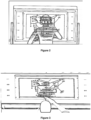
- the invention comprises a display (5) that digitally presents the drawing and production steps of the production to the operator who produces the cable harness (9).
- the invention comprises the following:
- it comprises a test device (7) connected to the test points (6) on the work surface (2) in order to determine whether the produced cable harness (9) works or not.
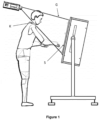
- the wiring board (1) of the present invention is connected on a support platform (1.1) with a movable structure that enables it to be carried.
- the support platform (1) is a mechanical structure/fixed framework that helps to adjust the working angle and height according to the operator who produces the cable harness (9).
- the support platform (1) can be moved easily by means of the wheels it comprises.
- a work surface (2) that is transparent, translucent to light, semi-permeable or can be turned into opaque structure thanks to the paint and film coating.
- the said work surface (2) is made of a transparent material coated with film and/or paint.
- This transparent work surface (2) is prepared to refract the light on it, to be translucent and to pass the light to a certain extent.
- the work surface (2) can be prepared by various methods such as reverse projection film, frosting effect on the surface and using silver-based translucent paint. This way, the image coming from the projector (3) is enabled to be seen on the transparent working surface (2) and the light is prevented from coming directly to the operator performing the work.
- the paths created for directing the production of the cable harness (9) are determined on the work surface (2).
- the holes on the working surface (2) are pin sockets (8.1).
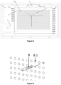
- the pins (8) rise and fall in the pin slots (8.1) located on the working surface (2), as seen in Figure 9 , according to the geometric shape of the cable harness (9) to be produced.
- the mechanical interface for the nails in the area to be inserted is in this element. Mechanical interface can be made using clips, helicoids, inserts etc. fastening members.
- the said mechanical interface is the unit formed by pin slots (8.1) and pins (8) on the working surface (2).
- said pins (8) can be of different types depending on their usage. Their geometries, angles etc. may change according to the work surface (2) and the shape of the pin sockets (8.1) on the work surface (2). In the wiring board (1) of the present invention, any pin (8) can be removed manually from the pin slot (8.1) and inserted into another desired pin slot (8.1).
- the image reflected on the work surface (2) is provided by a projector (3).
- Technical drawing of the cabling harness (9), image of the cabling harness test adapters, production information, etc. are reflected on the work surface (2) by the projector.
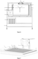
- the projector (3) is connected to the wiring board (1) by means of a connection apparatus (3.1) so that it stays behind the wiring board (1) as seen in Figure 4 .
- the projector (3) can be adjusted according to the desired focal point in order to focus the image in various sizes and to provide user comfort.
- the working surface (2) passes the image coming from the projector (3) and the image remains fixed on the work surface (2), which is at the point where the light is refracted.
- the image of the cable harness (9) to be produced is projected on the work surface (2) in the form of technical drawing.
- the projected image is detected by the sensors (4) and the detected data is transmitted to the control unit.
- the control unit determines the pins (8) closest to the detected image according to the drawing of the cable harness (9) to be produced by processing the data transmitted from the sensors (4).
- the pins (8) determined by the control unit rise as seen in Figure 7 in line with the command generated by the control unit and form the geometric shape of the cable harness (9) to be produced.
- the pins (8) can rise at the turns of the cables, at the separation of the branches and at places where the connectors come.
- the points at which the pins (8) will rise in the image are determined according to the general rules previously defined to the control unit.
- the lines continue uninterruptedly at the corners of the cable, a nail can be removed every 5 cm and the cable can be kept fixed between these pins.
- the junctions on the lines where the cables in the projected drawing are represented are determined and the pins come out according to the instructions from the joint.
- the laying of the cable on the work surface (2) is monitored in each laying step by the sensors (4).
- the sensors (4) transmit each detected laying action to the control unit. These transmitted data are processed by the control unit. If there is a difference between the image on the work surface (2) and the data transmitted by the sensor (4), the control unit detects the difference. The detected difference is transferred to the operator via the display (5). It is not possible to proceed to the next laying step until the difference is eliminated. If there is no difference between the image reflected from the projector (3) and the data transmitted by the sensor (4), the next laying step is shown on the display (5). Showing each laying step to the operator on the display (5) in order of operation provides convenience for the operator during cable laying. After the production is finished, the system resets itself and prepares for the next production.
- the advantage of the wiring board (1) of the present invention over existing techniques is explained in detail with the following example.
- all branches are marked for the laying of a harness of multiple branches.
- the marked cables are handled sequentially by the operator and read into a barcode and the information on where the cable will be laid is given to the operator according to the data received from the barcode. After the cables are laid in the relevant area by the operator, the accuracy is controlled manually by the operator.
- the wiring board (1), of the present invention since there is no separate marking of each branch and the reading of the marked branches, and the accuracy of the laying is automatically checked after the process, a significant gain is achieved in labor.
- the technical drawing of the cable harness (9) transferred to the working surface (2) by projection is detected by image processing technology by means of the sensors (4) and the pins (8) automatically rise and fall according to the rules created.
- image processing technology by means of the sensors (4) and the pins (8) automatically rise and fall according to the rules created.
- Machine Learning, Optical Thickness and Length Measurement, Color Based Analysis Skill are some of the methods used. For example, when the cable is laid from point A to point B, its difference can be seen from the image difference.
- the change in the wiring harness on the wiring board (1) can be understood by performing a yes or no analysis, or when a different color cable is laid, the difference can be determined by performing a color difference analysis.
- the cable harness (9) is supplied with appropriate volt and ampere values for the device to be used. These values are analyzed by mutual reading and success-failure information is given to the operator with the test software. Standard anonymous test devices (7) and standard software are used in tests.
- a projection device can be used, especially if it is desired to make the image projection at short distances, preferably a short range ratio (e.g. 0.46) projection device can be used.
- a short range ratio e.g. 0.46
- the image can also be reflected on the work surface (2) by using the mirroring method used in existing systems.
- the number of reflectors (3) can be increased according to the size of the wiring board (1).
- the wiring board (1) of the present invention is not specific to a single production, it is reconfigured for each production. Therefore, it is possible to produce more than one cable harness (9) with a single wiring board (1).
Landscapes
- Engineering & Computer Science (AREA)
- Manufacturing & Machinery (AREA)
- Combinations Of Printed Boards (AREA)
- General Factory Administration (AREA)
- Installation Of Indoor Wiring (AREA)
Claims (5)
- Plaque de câblage (1) qui permet la production de faisceau de câbles (9) sur celle-ci, ladite plaque comprenant les suivants :• une surface de travail (2) à structure matricielle perforée située sur la plaque de câblage (1),• au moins un projecteur (3) configuré pour projeter le dessin technique du faisceau de câbles (9) à réaliser sur la surface de travail (2),et caractérisée en ce que :• ledit projecteur (3) est raccordé à la plaque de câblage (1) au moyen d'un élément de raccordement (3.1) situé derrière la plaque de câblage (1),• une pluralité de broches (8) qui sont configurées pour être déplacées par montée et descente dans des fentes pour broches (8.1) sur la surface de travail (2),• au moins un capteur (4) configuré pour détecter l'image réfléchie sur la surface de travail (2) et pour transmettre les données détectées à la suite de la détection,• une unité de commande qui est configurée pour traiter les données transmises par le capteur (4), afin de déterminer les broches (8) situées au point le plus proche de l'image détectée et de permettre aux broches déterminées (8) de monter automatiquement.
- Plaque de câblage (1) selon la revendication 1, celle-ci comprenant une surface de travail transparente (2) revêtue d'un film et/ou de peinture.
- Plaque de câblage (1) selon la revendication 1, celle-ci comprenant un dispositif d'affichage (5) qui est configuré pour afficher numériquement le dessin de la production à l'opérateur produisant le faisceau de câbles (9) et de quelle broche (9) à quelle broche (9) l'opérateur doit poser le câble.
- Plaque de câblage (1) selon la revendication 1, celle-ci comprenant ;• au moins un capteur (4) configuré pour détecter l'image réfléchie sur la surface de travail (2) et les câbles posés sur la surface de travail (2) par l'opérateur réalisant le faisceau de câbles (9) et configuré pour transmettre les données détectées à la suite de la détection,• une unité de commande qui est configurée pour traiter les données transmises par le capteur (4) et qui est configurée pour détecter si une divergence existe entre le dessin technique réfléchi sur la surface de travail (2) et le câble posé par l'opérateur, et• dans le cas où une divergence est détectée par l'unité de commande, au moins un dispositif d'affichage (5) qui est configuré pour montrer cette divergence à l'opérateur en tant qu'erreur.
- Plaque de câblage (1) selon la revendication 1, celle-ci comprenant un dispositif d'essai (7) raccordé aux points d'essai (6) sur la surface de travail (2) afin de déterminer si le faisceau de câbles produit (9) fonctionne ou non une fois la production du faisceau de câbles (9) terminée.
Applications Claiming Priority (1)
| Application Number | Priority Date | Filing Date | Title |
|---|---|---|---|
| TR2020/04020A TR202004020A2 (tr) | 2020-03-16 | 2020-03-16 | Otomatik programlanabilir kablaj tahtası |
Publications (2)
| Publication Number | Publication Date |
|---|---|
| EP3886123A1 EP3886123A1 (fr) | 2021-09-29 |
| EP3886123B1 true EP3886123B1 (fr) | 2024-01-31 |
Family
ID=74844760
Family Applications (1)
| Application Number | Title | Priority Date | Filing Date |
|---|---|---|---|
| EP21159827.1A Active EP3886123B1 (fr) | 2020-03-16 | 2021-03-01 | Plaque de câblage programmable automatique |
Country Status (2)
| Country | Link |
|---|---|
| EP (1) | EP3886123B1 (fr) |
| TR (1) | TR202004020A2 (fr) |
Family Cites Families (8)
| Publication number | Priority date | Publication date | Assignee | Title |
|---|---|---|---|---|
| US4979544A (en) * | 1988-09-30 | 1990-12-25 | The Boeing Company | Universal wire harness form board assembly |
| WO2003031094A1 (fr) * | 2001-10-11 | 2003-04-17 | Laser Projection Technologies, Inc. | Procede et systeme de table de routage de faisceaux de cables a projection |
| DE102011084786B4 (de) * | 2011-10-19 | 2013-11-14 | S-Y Systems Technologies Europe Gmbh | Verfahren und Formbrett zum Herstellen eines Kabelbaumes |
| ES2443265B1 (es) | 2012-08-16 | 2014-11-13 | Eads Construcciones Aeronauticas, S.A. | Banco de fabricación o verificación de mazos eléctricos |
| DE102015011822A1 (de) * | 2015-09-09 | 2016-03-31 | Daimler Ag | Fertigungshilfe zum Herstellen eines Leitungssatzes, inbesondere eines Kabelbaums für eine Kraftwagen |
| DE102016119867B4 (de) * | 2016-10-18 | 2018-07-12 | Kromberg & Schubert Gmbh | Kabelbaumformbrett und Verfahren zur Herstellung eines Leitungssatzes |
| TR201723043A2 (tr) | 2017-12-29 | 2019-07-22 | Aselsan Elektronik Sanayi Ve Ticaret Anonim Sirketi | Konfigüre Edilebilir Elektro-Mekanik Kablaj Tahtası |
| TR201801092U5 (tr) | 2018-01-25 | 2019-08-21 | Aselsan Elektronik Sanayi Ve Ticaret As | Gölge oluşmadan görüntünün yansitilmasini sağlayan si̇stem |
-
2020
- 2020-03-16 TR TR2020/04020A patent/TR202004020A2/tr unknown
-
2021
- 2021-03-01 EP EP21159827.1A patent/EP3886123B1/fr active Active
Also Published As
| Publication number | Publication date |
|---|---|
| TR202004020A2 (tr) | 2021-09-21 |
| EP3886123A1 (fr) | 2021-09-29 |
Similar Documents
| Publication | Publication Date | Title |
|---|---|---|
| EP2575147B1 (fr) | Établi pour la fabrication ou la vérification de faisceaux de câbles électriques | |
| EP2910430B1 (fr) | Système pour la réalisation de tests électriques de harnais de câblage électrique | |
| US4638232A (en) | Method and apparatus for calibrating a positioning system | |
| EP3109624B1 (fr) | Systèmes et procédés permettant l'inspection automatique de segments de fils | |
| US6196441B1 (en) | Solder bump measuring method and apparatus | |
| US6366689B1 (en) | 3D profile analysis for surface contour inspection | |
| US20170003232A1 (en) | System and method for measuring reflected optical distortion in contoured glass sheets | |
| GB2207243A (en) | Automatic quality control measuring system for automotive assembly line or the like. | |
| US5526043A (en) | Automatic video display testing and adjusting system | |
| EP3886123A1 (fr) | Plaque de câblage programmable automatique | |
| EP0486272B1 (fr) | Méthode d'inspection des dislocations axiales des connecteurs optiques multifibres | |
| US11295406B2 (en) | Image management device | |
| US5777886A (en) | Programmable lead conditioner | |
| CN116105915B (zh) | 一种车载开关多方向拨杆力测试设备及测试方法 | |
| US7168369B2 (en) | Device for moving a machine | |
| CN210198327U (zh) | 2d及3d量测装置 | |
| JPH0251050A (ja) | 位置ずれ補正方法 | |
| EP0347860A2 (fr) | Méthode de diagnostic pour tester la normalité de la transmission de données entre des unités de commande reliées sériellement | |
| EP4303562A1 (fr) | Procédé et système permettant d'effectuer une analyse de forme et de taille de toutes les particules solides par traitement d'image | |
| US12436574B2 (en) | System for memory module mounting test and method therefor | |
| US20060147103A1 (en) | Device for identifying a structure to be applied to a substrate, and corresponding methods | |
| US20240427307A1 (en) | Tool monitoring system and method of use thereof | |
| JPH0814610B2 (ja) | 回路基板検査装置 | |
| CN117109880A (zh) | 一种ned产品检测设备及其检测方法 | |
| CN121741772A (zh) | 卫星单机多特征一体化验收检测设备及方法 |
Legal Events
| Date | Code | Title | Description |
|---|---|---|---|
| PUAI | Public reference made under article 153(3) epc to a published international application that has entered the european phase |
Free format text: ORIGINAL CODE: 0009012 |
|
| STAA | Information on the status of an ep patent application or granted ep patent |
Free format text: STATUS: THE APPLICATION HAS BEEN PUBLISHED |
|
| AK | Designated contracting states |
Kind code of ref document: A1 Designated state(s): AL AT BE BG CH CY CZ DE DK EE ES FI FR GB GR HR HU IE IS IT LI LT LU LV MC MK MT NL NO PL PT RO RS SE SI SK SM TR |
|
| STAA | Information on the status of an ep patent application or granted ep patent |
Free format text: STATUS: REQUEST FOR EXAMINATION WAS MADE |
|
| 17P | Request for examination filed |
Effective date: 20211224 |
|
| RBV | Designated contracting states (corrected) |
Designated state(s): AL AT BE BG CH CY CZ DE DK EE ES FI FR GB GR HR HU IE IS IT LI LT LU LV MC MK MT NL NO PL PT RO RS SE SI SK SM TR |
|
| P01 | Opt-out of the competence of the unified patent court (upc) registered |
Effective date: 20230601 |
|
| GRAP | Despatch of communication of intention to grant a patent |
Free format text: ORIGINAL CODE: EPIDOSNIGR1 |
|
| STAA | Information on the status of an ep patent application or granted ep patent |
Free format text: STATUS: GRANT OF PATENT IS INTENDED |
|
| INTG | Intention to grant announced |
Effective date: 20230914 |
|
| GRAS | Grant fee paid |
Free format text: ORIGINAL CODE: EPIDOSNIGR3 |
|
| GRAA | (expected) grant |
Free format text: ORIGINAL CODE: 0009210 |
|
| STAA | Information on the status of an ep patent application or granted ep patent |
Free format text: STATUS: THE PATENT HAS BEEN GRANTED |
|
| AK | Designated contracting states |
Kind code of ref document: B1 Designated state(s): AL AT BE BG CH CY CZ DE DK EE ES FI FR GB GR HR HU IE IS IT LI LT LU LV MC MK MT NL NO PL PT RO RS SE SI SK SM TR |
|
| REG | Reference to a national code |
Ref country code: GB Ref legal event code: FG4D Ref country code: CH Ref legal event code: EP |
|
| REG | Reference to a national code |
Ref country code: DE Ref legal event code: R096 Ref document number: 602021008819 Country of ref document: DE |
|
| REG | Reference to a national code |
Ref country code: IE Ref legal event code: FG4D |
|
| REG | Reference to a national code |
Ref country code: LT Ref legal event code: MG9D |
|
| REG | Reference to a national code |
Ref country code: NL Ref legal event code: MP Effective date: 20240131 |
|
| PG25 | Lapsed in a contracting state [announced via postgrant information from national office to epo] |
Ref country code: IS Free format text: LAPSE BECAUSE OF FAILURE TO SUBMIT A TRANSLATION OF THE DESCRIPTION OR TO PAY THE FEE WITHIN THE PRESCRIBED TIME-LIMIT Effective date: 20240531 |
|
| PG25 | Lapsed in a contracting state [announced via postgrant information from national office to epo] |
Ref country code: LT Free format text: LAPSE BECAUSE OF FAILURE TO SUBMIT A TRANSLATION OF THE DESCRIPTION OR TO PAY THE FEE WITHIN THE PRESCRIBED TIME-LIMIT Effective date: 20240131 |
|
| PG25 | Lapsed in a contracting state [announced via postgrant information from national office to epo] |
Ref country code: GR Free format text: LAPSE BECAUSE OF FAILURE TO SUBMIT A TRANSLATION OF THE DESCRIPTION OR TO PAY THE FEE WITHIN THE PRESCRIBED TIME-LIMIT Effective date: 20240501 |
|
| REG | Reference to a national code |
Ref country code: AT Ref legal event code: MK05 Ref document number: 1654432 Country of ref document: AT Kind code of ref document: T Effective date: 20240131 |
|
| PG25 | Lapsed in a contracting state [announced via postgrant information from national office to epo] |
Ref country code: NL Free format text: LAPSE BECAUSE OF FAILURE TO SUBMIT A TRANSLATION OF THE DESCRIPTION OR TO PAY THE FEE WITHIN THE PRESCRIBED TIME-LIMIT Effective date: 20240131 Ref country code: RS Free format text: LAPSE BECAUSE OF FAILURE TO SUBMIT A TRANSLATION OF THE DESCRIPTION OR TO PAY THE FEE WITHIN THE PRESCRIBED TIME-LIMIT Effective date: 20240430 Ref country code: HR Free format text: LAPSE BECAUSE OF FAILURE TO SUBMIT A TRANSLATION OF THE DESCRIPTION OR TO PAY THE FEE WITHIN THE PRESCRIBED TIME-LIMIT Effective date: 20240131 |
|
| PG25 | Lapsed in a contracting state [announced via postgrant information from national office to epo] |
Ref country code: ES Free format text: LAPSE BECAUSE OF FAILURE TO SUBMIT A TRANSLATION OF THE DESCRIPTION OR TO PAY THE FEE WITHIN THE PRESCRIBED TIME-LIMIT Effective date: 20240131 |
|
| PG25 | Lapsed in a contracting state [announced via postgrant information from national office to epo] |
Ref country code: AT Free format text: LAPSE BECAUSE OF FAILURE TO SUBMIT A TRANSLATION OF THE DESCRIPTION OR TO PAY THE FEE WITHIN THE PRESCRIBED TIME-LIMIT Effective date: 20240131 |
|
| PG25 | Lapsed in a contracting state [announced via postgrant information from national office to epo] |
Ref country code: RS Free format text: LAPSE BECAUSE OF FAILURE TO SUBMIT A TRANSLATION OF THE DESCRIPTION OR TO PAY THE FEE WITHIN THE PRESCRIBED TIME-LIMIT Effective date: 20240430 Ref country code: NO Free format text: LAPSE BECAUSE OF FAILURE TO SUBMIT A TRANSLATION OF THE DESCRIPTION OR TO PAY THE FEE WITHIN THE PRESCRIBED TIME-LIMIT Effective date: 20240430 Ref country code: NL Free format text: LAPSE BECAUSE OF FAILURE TO SUBMIT A TRANSLATION OF THE DESCRIPTION OR TO PAY THE FEE WITHIN THE PRESCRIBED TIME-LIMIT Effective date: 20240131 Ref country code: LT Free format text: LAPSE BECAUSE OF FAILURE TO SUBMIT A TRANSLATION OF THE DESCRIPTION OR TO PAY THE FEE WITHIN THE PRESCRIBED TIME-LIMIT Effective date: 20240131 Ref country code: IS Free format text: LAPSE BECAUSE OF FAILURE TO SUBMIT A TRANSLATION OF THE DESCRIPTION OR TO PAY THE FEE WITHIN THE PRESCRIBED TIME-LIMIT Effective date: 20240531 Ref country code: HR Free format text: LAPSE BECAUSE OF FAILURE TO SUBMIT A TRANSLATION OF THE DESCRIPTION OR TO PAY THE FEE WITHIN THE PRESCRIBED TIME-LIMIT Effective date: 20240131 Ref country code: GR Free format text: LAPSE BECAUSE OF FAILURE TO SUBMIT A TRANSLATION OF THE DESCRIPTION OR TO PAY THE FEE WITHIN THE PRESCRIBED TIME-LIMIT Effective date: 20240501 Ref country code: FI Free format text: LAPSE BECAUSE OF FAILURE TO SUBMIT A TRANSLATION OF THE DESCRIPTION OR TO PAY THE FEE WITHIN THE PRESCRIBED TIME-LIMIT Effective date: 20240131 Ref country code: ES Free format text: LAPSE BECAUSE OF FAILURE TO SUBMIT A TRANSLATION OF THE DESCRIPTION OR TO PAY THE FEE WITHIN THE PRESCRIBED TIME-LIMIT Effective date: 20240131 Ref country code: BG Free format text: LAPSE BECAUSE OF FAILURE TO SUBMIT A TRANSLATION OF THE DESCRIPTION OR TO PAY THE FEE WITHIN THE PRESCRIBED TIME-LIMIT Effective date: 20240131 Ref country code: AT Free format text: LAPSE BECAUSE OF FAILURE TO SUBMIT A TRANSLATION OF THE DESCRIPTION OR TO PAY THE FEE WITHIN THE PRESCRIBED TIME-LIMIT Effective date: 20240131 |
|
| PG25 | Lapsed in a contracting state [announced via postgrant information from national office to epo] |
Ref country code: PT Free format text: LAPSE BECAUSE OF FAILURE TO SUBMIT A TRANSLATION OF THE DESCRIPTION OR TO PAY THE FEE WITHIN THE PRESCRIBED TIME-LIMIT Effective date: 20240531 Ref country code: PL Free format text: LAPSE BECAUSE OF FAILURE TO SUBMIT A TRANSLATION OF THE DESCRIPTION OR TO PAY THE FEE WITHIN THE PRESCRIBED TIME-LIMIT Effective date: 20240131 |
|
| PG25 | Lapsed in a contracting state [announced via postgrant information from national office to epo] |
Ref country code: SE Free format text: LAPSE BECAUSE OF FAILURE TO SUBMIT A TRANSLATION OF THE DESCRIPTION OR TO PAY THE FEE WITHIN THE PRESCRIBED TIME-LIMIT Effective date: 20240131 Ref country code: PT Free format text: LAPSE BECAUSE OF FAILURE TO SUBMIT A TRANSLATION OF THE DESCRIPTION OR TO PAY THE FEE WITHIN THE PRESCRIBED TIME-LIMIT Effective date: 20240531 Ref country code: PL Free format text: LAPSE BECAUSE OF FAILURE TO SUBMIT A TRANSLATION OF THE DESCRIPTION OR TO PAY THE FEE WITHIN THE PRESCRIBED TIME-LIMIT Effective date: 20240131 Ref country code: LV Free format text: LAPSE BECAUSE OF FAILURE TO SUBMIT A TRANSLATION OF THE DESCRIPTION OR TO PAY THE FEE WITHIN THE PRESCRIBED TIME-LIMIT Effective date: 20240131 |
|
| REG | Reference to a national code |
Ref country code: DE Ref legal event code: R119 Ref document number: 602021008819 Country of ref document: DE |
|
| PG25 | Lapsed in a contracting state [announced via postgrant information from national office to epo] |
Ref country code: DK Free format text: LAPSE BECAUSE OF FAILURE TO SUBMIT A TRANSLATION OF THE DESCRIPTION OR TO PAY THE FEE WITHIN THE PRESCRIBED TIME-LIMIT Effective date: 20240131 |
|
| PG25 | Lapsed in a contracting state [announced via postgrant information from national office to epo] |
Ref country code: SM Free format text: LAPSE BECAUSE OF FAILURE TO SUBMIT A TRANSLATION OF THE DESCRIPTION OR TO PAY THE FEE WITHIN THE PRESCRIBED TIME-LIMIT Effective date: 20240131 |
|
| PG25 | Lapsed in a contracting state [announced via postgrant information from national office to epo] |
Ref country code: CZ Free format text: LAPSE BECAUSE OF FAILURE TO SUBMIT A TRANSLATION OF THE DESCRIPTION OR TO PAY THE FEE WITHIN THE PRESCRIBED TIME-LIMIT Effective date: 20240131 Ref country code: EE Free format text: LAPSE BECAUSE OF FAILURE TO SUBMIT A TRANSLATION OF THE DESCRIPTION OR TO PAY THE FEE WITHIN THE PRESCRIBED TIME-LIMIT Effective date: 20240131 |
|
| PG25 | Lapsed in a contracting state [announced via postgrant information from national office to epo] |
Ref country code: SK Free format text: LAPSE BECAUSE OF FAILURE TO SUBMIT A TRANSLATION OF THE DESCRIPTION OR TO PAY THE FEE WITHIN THE PRESCRIBED TIME-LIMIT Effective date: 20240131 |
|
| PG25 | Lapsed in a contracting state [announced via postgrant information from national office to epo] |
Ref country code: SM Free format text: LAPSE BECAUSE OF FAILURE TO SUBMIT A TRANSLATION OF THE DESCRIPTION OR TO PAY THE FEE WITHIN THE PRESCRIBED TIME-LIMIT Effective date: 20240131 Ref country code: SK Free format text: LAPSE BECAUSE OF FAILURE TO SUBMIT A TRANSLATION OF THE DESCRIPTION OR TO PAY THE FEE WITHIN THE PRESCRIBED TIME-LIMIT Effective date: 20240131 Ref country code: RO Free format text: LAPSE BECAUSE OF FAILURE TO SUBMIT A TRANSLATION OF THE DESCRIPTION OR TO PAY THE FEE WITHIN THE PRESCRIBED TIME-LIMIT Effective date: 20240131 Ref country code: EE Free format text: LAPSE BECAUSE OF FAILURE TO SUBMIT A TRANSLATION OF THE DESCRIPTION OR TO PAY THE FEE WITHIN THE PRESCRIBED TIME-LIMIT Effective date: 20240131 Ref country code: DK Free format text: LAPSE BECAUSE OF FAILURE TO SUBMIT A TRANSLATION OF THE DESCRIPTION OR TO PAY THE FEE WITHIN THE PRESCRIBED TIME-LIMIT Effective date: 20240131 Ref country code: CZ Free format text: LAPSE BECAUSE OF FAILURE TO SUBMIT A TRANSLATION OF THE DESCRIPTION OR TO PAY THE FEE WITHIN THE PRESCRIBED TIME-LIMIT Effective date: 20240131 |
|
| REG | Reference to a national code |
Ref country code: CH Ref legal event code: PL |
|
| PG25 | Lapsed in a contracting state [announced via postgrant information from national office to epo] |
Ref country code: LU Free format text: LAPSE BECAUSE OF NON-PAYMENT OF DUE FEES Effective date: 20240301 |
|
| PG25 | Lapsed in a contracting state [announced via postgrant information from national office to epo] |
Ref country code: MC Free format text: LAPSE BECAUSE OF FAILURE TO SUBMIT A TRANSLATION OF THE DESCRIPTION OR TO PAY THE FEE WITHIN THE PRESCRIBED TIME-LIMIT Effective date: 20240131 |
|
| PG25 | Lapsed in a contracting state [announced via postgrant information from national office to epo] |
Ref country code: MC Free format text: LAPSE BECAUSE OF FAILURE TO SUBMIT A TRANSLATION OF THE DESCRIPTION OR TO PAY THE FEE WITHIN THE PRESCRIBED TIME-LIMIT Effective date: 20240131 Ref country code: LU Free format text: LAPSE BECAUSE OF NON-PAYMENT OF DUE FEES Effective date: 20240301 |
|
| PG25 | Lapsed in a contracting state [announced via postgrant information from national office to epo] |
Ref country code: IT Free format text: LAPSE BECAUSE OF FAILURE TO SUBMIT A TRANSLATION OF THE DESCRIPTION OR TO PAY THE FEE WITHIN THE PRESCRIBED TIME-LIMIT Effective date: 20240131 |
|
| PLBE | No opposition filed within time limit |
Free format text: ORIGINAL CODE: 0009261 |
|
| STAA | Information on the status of an ep patent application or granted ep patent |
Free format text: STATUS: NO OPPOSITION FILED WITHIN TIME LIMIT |
|
| REG | Reference to a national code |
Ref country code: BE Ref legal event code: MM Effective date: 20240331 |
|
| PG25 | Lapsed in a contracting state [announced via postgrant information from national office to epo] |
Ref country code: IT Free format text: LAPSE BECAUSE OF FAILURE TO SUBMIT A TRANSLATION OF THE DESCRIPTION OR TO PAY THE FEE WITHIN THE PRESCRIBED TIME-LIMIT Effective date: 20240131 |
|
| 26N | No opposition filed |
Effective date: 20241101 |
|
| PG25 | Lapsed in a contracting state [announced via postgrant information from national office to epo] |
Ref country code: DE Free format text: LAPSE BECAUSE OF NON-PAYMENT OF DUE FEES Effective date: 20241001 |
|
| PG25 | Lapsed in a contracting state [announced via postgrant information from national office to epo] |
Ref country code: BE Free format text: LAPSE BECAUSE OF NON-PAYMENT OF DUE FEES Effective date: 20240331 |
|
| PG25 | Lapsed in a contracting state [announced via postgrant information from national office to epo] |
Ref country code: FR Free format text: LAPSE BECAUSE OF NON-PAYMENT OF DUE FEES Effective date: 20240331 |
|
| PG25 | Lapsed in a contracting state [announced via postgrant information from national office to epo] |
Ref country code: IE Free format text: LAPSE BECAUSE OF NON-PAYMENT OF DUE FEES Effective date: 20240301 |
|
| PG25 | Lapsed in a contracting state [announced via postgrant information from national office to epo] |
Ref country code: IE Free format text: LAPSE BECAUSE OF NON-PAYMENT OF DUE FEES Effective date: 20240301 Ref country code: FR Free format text: LAPSE BECAUSE OF NON-PAYMENT OF DUE FEES Effective date: 20240331 Ref country code: DE Free format text: LAPSE BECAUSE OF NON-PAYMENT OF DUE FEES Effective date: 20241001 Ref country code: BE Free format text: LAPSE BECAUSE OF NON-PAYMENT OF DUE FEES Effective date: 20240331 Ref country code: CH Free format text: LAPSE BECAUSE OF NON-PAYMENT OF DUE FEES Effective date: 20240331 |
|
| PG25 | Lapsed in a contracting state [announced via postgrant information from national office to epo] |
Ref country code: SI Free format text: LAPSE BECAUSE OF FAILURE TO SUBMIT A TRANSLATION OF THE DESCRIPTION OR TO PAY THE FEE WITHIN THE PRESCRIBED TIME-LIMIT Effective date: 20240131 |
|
| PG25 | Lapsed in a contracting state [announced via postgrant information from national office to epo] |
Ref country code: CY Free format text: LAPSE BECAUSE OF FAILURE TO SUBMIT A TRANSLATION OF THE DESCRIPTION OR TO PAY THE FEE WITHIN THE PRESCRIBED TIME-LIMIT; INVALID AB INITIO Effective date: 20210301 |
|
| PG25 | Lapsed in a contracting state [announced via postgrant information from national office to epo] |
Ref country code: HU Free format text: LAPSE BECAUSE OF FAILURE TO SUBMIT A TRANSLATION OF THE DESCRIPTION OR TO PAY THE FEE WITHIN THE PRESCRIBED TIME-LIMIT; INVALID AB INITIO Effective date: 20210301 |
|
| GBPC | Gb: european patent ceased through non-payment of renewal fee |
Effective date: 20250301 |
|
| PG25 | Lapsed in a contracting state [announced via postgrant information from national office to epo] |
Ref country code: TR Free format text: LAPSE BECAUSE OF FAILURE TO SUBMIT A TRANSLATION OF THE DESCRIPTION OR TO PAY THE FEE WITHIN THE PRESCRIBED TIME-LIMIT Effective date: 20240131 |
|
| PG25 | Lapsed in a contracting state [announced via postgrant information from national office to epo] |
Ref country code: GB Free format text: LAPSE BECAUSE OF NON-PAYMENT OF DUE FEES Effective date: 20250301 |