EP3887103B1 - Dispositif de perforation und machine avec le dispositif - Google Patents
Dispositif de perforation und machine avec le dispositif Download PDFInfo
- Publication number
- EP3887103B1 EP3887103B1 EP19831887.5A EP19831887A EP3887103B1 EP 3887103 B1 EP3887103 B1 EP 3887103B1 EP 19831887 A EP19831887 A EP 19831887A EP 3887103 B1 EP3887103 B1 EP 3887103B1
- Authority
- EP
- European Patent Office
- Prior art keywords
- support beam
- blade
- perforating
- counter
- blades
- Prior art date
- Legal status (The legal status is an assumption and is not a legal conclusion. Google has not performed a legal analysis and makes no representation as to the accuracy of the status listed.)
- Active
Links
Images

Classifications
-
- B—PERFORMING OPERATIONS; TRANSPORTING
- B26—HAND CUTTING TOOLS; CUTTING; SEVERING
- B26D—CUTTING; DETAILS COMMON TO MACHINES FOR PERFORATING, PUNCHING, CUTTING-OUT, STAMPING-OUT OR SEVERING
- B26D1/00—Cutting through work characterised by the nature or movement of the cutting member or particular materials not otherwise provided for; Apparatus or machines therefor; Cutting members therefor
- B26D1/01—Cutting through work characterised by the nature or movement of the cutting member or particular materials not otherwise provided for; Apparatus or machines therefor; Cutting members therefor involving a cutting member which does not travel with the work
- B26D1/12—Cutting through work characterised by the nature or movement of the cutting member or particular materials not otherwise provided for; Apparatus or machines therefor; Cutting members therefor involving a cutting member which does not travel with the work having a cutting member moving about an axis
- B26D1/25—Cutting through work characterised by the nature or movement of the cutting member or particular materials not otherwise provided for; Apparatus or machines therefor; Cutting members therefor involving a cutting member which does not travel with the work having a cutting member moving about an axis with a non-circular cutting member
- B26D1/34—Cutting through work characterised by the nature or movement of the cutting member or particular materials not otherwise provided for; Apparatus or machines therefor; Cutting members therefor involving a cutting member which does not travel with the work having a cutting member moving about an axis with a non-circular cutting member moving about an axis parallel to the line of cut
- B26D1/38—Cutting through work characterised by the nature or movement of the cutting member or particular materials not otherwise provided for; Apparatus or machines therefor; Cutting members therefor involving a cutting member which does not travel with the work having a cutting member moving about an axis with a non-circular cutting member moving about an axis parallel to the line of cut and coacting with a fixed blade or other fixed member
- B26D1/385—Cutting through work characterised by the nature or movement of the cutting member or particular materials not otherwise provided for; Apparatus or machines therefor; Cutting members therefor involving a cutting member which does not travel with the work having a cutting member moving about an axis with a non-circular cutting member moving about an axis parallel to the line of cut and coacting with a fixed blade or other fixed member for thin material, e.g. for sheets, strips or the like
-
- B—PERFORMING OPERATIONS; TRANSPORTING
- B26—HAND CUTTING TOOLS; CUTTING; SEVERING
- B26D—CUTTING; DETAILS COMMON TO MACHINES FOR PERFORATING, PUNCHING, CUTTING-OUT, STAMPING-OUT OR SEVERING
- B26D7/00—Details of apparatus for cutting, cutting-out, stamping-out, punching, perforating, or severing by means other than cutting
- B26D7/26—Means for mounting or adjusting the cutting member; Means for adjusting the stroke of the cutting member
-
- B—PERFORMING OPERATIONS; TRANSPORTING
- B26—HAND CUTTING TOOLS; CUTTING; SEVERING
- B26F—PERFORATING; PUNCHING; CUTTING-OUT; STAMPING-OUT; SEVERING BY MEANS OTHER THAN CUTTING
- B26F1/00—Perforating; Punching; Cutting-out; Stamping-out; Apparatus therefor
- B26F1/18—Perforating by slitting, i.e. forming cuts closed at their ends without removal of material
- B26F1/20—Perforating by slitting, i.e. forming cuts closed at their ends without removal of material with tools carried by a rotating drum or similar support
-
- B—PERFORMING OPERATIONS; TRANSPORTING
- B65—CONVEYING; PACKING; STORING; HANDLING THIN OR FILAMENTARY MATERIAL
- B65H—HANDLING THIN OR FILAMENTARY MATERIAL, e.g. SHEETS, WEBS, CABLES
- B65H35/00—Delivering articles from cutting or line-perforating machines; Article or web delivery apparatus incorporating cutting or line-perforating devices, e.g. adhesive tape dispensers
- B65H35/04—Delivering articles from cutting or line-perforating machines; Article or web delivery apparatus incorporating cutting or line-perforating devices, e.g. adhesive tape dispensers from or with transverse cutters or perforators
- B65H35/08—Delivering articles from cutting or line-perforating machines; Article or web delivery apparatus incorporating cutting or line-perforating devices, e.g. adhesive tape dispensers from or with transverse cutters or perforators from or with revolving, e.g. cylinder, cutters or perforators
Definitions
- the present invention relates to improvements to perforating devices for perforating continuous web materials along perforation lines transverse to the web material feeding direction.
- devices are disclosed herein for perforating tissue paper, for example for producing toilet paper, kitchen towels and other cellulose products wound in rolls.
- the continuous web material In the production of continuous web material wound in rolls, the continuous web material is often divided into single sheets through transverse perforation lines. The single sheets remain joined together until they are used, i.e. when the user separates one or more sheets by tearing along the respective perforation lines.
- the continuous webs of cellulose material used for producing packs of rolls or wound webs for example toilet paper, kitchen towels and the like, are perforated in this way.
- the perforation lines are made by means of rotating blades co-acting with a fixed counter-blade.
- the fixed counter-blade usually has a discontinuous cutting edge, and the rotating blades have respective continuous cutting edges.
- the cut obtained is discontinuous and, between segments of cut web material, segments of intact material are interposed, that are torn for use.
- the length of the cut segments and that of the uncut segments of material and/or the pitch of perforations, i.e. of cuts may vary from a product to the other, for example according to the type of finished product and/or to the quality of the web material used. For instance, the perforation pitch of in toilet paper is different than that in kitchen towels.
- Perforating devices have been thus designed, which allow to mount more counter-blades, for selectively working with one or the other of a plurality of counter-blades having toothed, i.e. discontinuous, cutting edges, different from one another.
- US 6,431,491 discloses a system having a central beam supporting two counter-blades that co-act selectively with one or the other of two distinct rotating rollers, each of which supports a plurality of blades.
- a perforating device for perforating a web material comprising:a first blade-holder adapted to rotate around a respective first rotation axis and on which a first perforating blade is mounted; a support beam, on which a plurality of counter-blades are mounted; said support beam being angularly adjustable around a selection rotation axis thereof in a plurality of angular working positions, in each angular working position one of the counter-blades being in an operative position; an actuating device adapted to rotate the support beam in order to arrange it selectively in one of said angular working positions.
- the known perforating devices have some drawbacks in terms of flexibility, i.e. as regards the number of counter-blades that can be alternatively used.
- the prior art perforating devices have also further drawbacks as regards the complexity of switching between different operating modes, each of which is based on the selective use of one or the other of several counter-blades, with which the perforating device is provided.
- the switching from one operating mode to the other is carried out manually by the operator, with complex operations for installing and removing the blades. Therefore, these operations require machine shut down and intervention of professional operators, and entail times varying also according to the operator's ability, affecting the production planning and the productivity of the production line.
- manual operations may entail risks for the operators.
- a perforating device for perforating a web material, comprising a first blade-holder adapted to rotate around a respective first rotation axis and on which at least a first perforating blade is mounted; and further comprising a support beam, on which a plurality of counter-blades are mounted, for example two or more counter-blades.
- the support beam is angularly adjustable around a selection rotation axis thereof in a plurality of working positions, i.e. at least two working positions. In each angular working position one of the counter-blades mounted on the support beam is selectively brought in an operative position.
- the term "operative position" refers to a position where the counter-blades co-acts with the rotating blade(s) of the blade-holder or of one of the blade-holders, with which the perforating device is provided.
- the perforating device also has a movable abutment adapted to co-act with the support beam of the counter-blades, and a first actuating device adapted to move the movable abutment between an active position, where the movable abutment co-acts with the support beam, and an idle position, where the movable abutment is spaced from the support beam.
- the movable abutment In the active position the movable abutment, co-acting with the support beam, defines a preset angular position of the support beam, to which an active position or working position of a counter-blade corresponds.
- the support beam In the idle position, the support beam is free to rotate around the axis thereof, without touching the movable abutment, to allow the support beam to be positioned in the desired angular position.
- the movable abutment can be brought to the active position and define the working position of the support beam.
- the rotation movement of the support beam is controlled by a second actuating device adapted to rotate the support beam in order to arrange it selectively in one of said angular working positions.
- the perforating device so configured is adapted to be equipped with a plurality of selectable counter-blades, for example two and preferably more than two counter-blades, and to be configured to bring in working position any one of the various counter-blades in a servo-assisted manner.
- the actuating devices may interface a control unit, so that the operator can set the configuration of the perforating device, for example through a user interface, a control panel, a tablet or other mobile device.
- the movable abutment may be provided with a movement towards, and away from, the selection rotation axis of the support beam.
- the movable abutment may move parallel to the selection rotation axis of the support beam.
- Combined movements may be also provided, with a component parallel to the selection rotation axis and a component orthogonal to the selection rotation axis.
- the support beam may comprise a body elongated according to the selection rotation axis and the counter-blades may extend parallel to the selection rotation axis or helically around the selection rotation axis.
- the elongated body of the beam may be supported, at the ends thereof, on side walls of a bearing structure, for example thorough end shanks.
- the blades and/or the counter-blades may be provided with a translation movement parallel to the rotation axis of the rotating blade-holder and/or of the support beam of the counter-blades, to avoid wear concentrated in the continuous cutting edges of the blades due to the toothed, i.e. discontinuous, shape of the cutting edge of the counter-blades.
- the support beam is integral with a plurality of abutment surfaces adapted to co-act selectively with the movable abutment.
- the abutment surfaces may be provided in a flange integral with the support beam.
- the abutment surfaces may extend approximately radially from a perimeter edge of the flange towards the center of the flange, i.e. towards the selection rotation axis.
- the second actuating device may be constituted only by an electronically controlled electric motor adapted to rotate the support beam selectively in order to arrange it in a plurality of alternative angular positions.
- the second actuating device may comprise more actuators.
- the second actuating device may comprise a first actuator adapted to rotate the support beam around the selection rotation axis in order to arrange angularly the support beam in one of a plurality of alternative angular arrangements, to each of which at least one angular working position corresponds.
- the second actuating device may further comprise a second actuator adapted to bring the support beam to said at least one angular working position, where the movable abutment touches a respective abutment surface integral with the support beam.
- the first actuator performs a preliminary angular positioning
- the second actuator moves the support beam towards the movable abutment, so that the support beam takes the right angular working position with respect to the rotating roller, on which the blade(s) co-acting with the selected counter-blade is(are) mounted.
- the first actuator is an electric actuator, in particular an electric gear motor
- the second actuator is a linear actuator, in particular a cylinder-piston actuator.
- the two actuators may be controlled in coordinated manner, so as firstly to select the angular position of the support beam and then to move the support beam towards the movable abutment.
- the second actuating device may be configured to make a quick emergency movement, so as to bring the counter-blade in a non-working position, for example in case of overload between the counter-blade and the blade(s). This situation may occur, for example, in case of an unexpected accumulation of web material due to the accidental breakage of the same web material.
- the device may comprise a reciprocating translation device, adapted to apply to the support beam a reciprocating translation movement parallel to the longitudinal extension of said support beam.
- the reciprocating translation movement may be obtained, for example, through an electric motor driving into rotation a cam, to which the support beam is fastened.
- the perforating device may have a blade-holder, for example acting as a rotating roller, on which one or more blades are mounted, in particularly advantageous embodiments the device has two rotating blade-holders, arranged with the support beam of the counter-blades in intermediate position between the two rotating blade-holders.
- the perforating device whose support beam of the counter-blades may comprise a plurality of counter-blades adapted to co-act with the rotating blade(s) of the first blade-holder and a further plurality of counter-blades adapted to co-act with the rotating blade(s) of the second blade-holder.
- a converting machine for converting a web material comprising converting members and a perforating device as described above.
- converting machine refers to any machine converting the web material in a finished or semi-finished product.
- the converting machine may be, for example, a rewinder for producing tissue paper rolls.
- the converting members may comprise winding members adapted to wind the previously perforated web material into single rolls.
- the perforating device comprises a support beam, on which a plurality of perforating counter-blades are mounted, each of which can selectively co-act with one or the other of two rotating blade-holders.
- the support beam of the counter-blades can be positioned in any one of a plurality of selective angular positions, in each of which at least one counter-blade can be brought in working position to co-act with a rotating blade-holder.
- the selective positioning system which makes the support beam angularly rotate and which places it correctly angularly in working position, may comprise two distinct actuators, as described below.
- each blade-holder is in the form of a rotating roller and, in the present description, it will be referred to namely as "rotating roller".
- rotating roller the configuration is not mandatory and the blade-holder may have a different form.
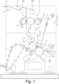
- number 1 generically indicates a converting machine for converting a continuous web material N, for example a single-ply or multi-ply web of tissue paper, i.e. a web comprised of a single cellulose ply or of a plurality of cellulose plies joined together.
- the rewinding machine 1 comprises converting members converting the continuous web material N in rolls R.
- the rolls are formed around tubular winding cores T fed by means of a conveyor 7 to a set of winding members 3.
- the rewinder schematically illustrated in Fig. 1 and only briefly described below, is only one embodiment of a converting machine that can have any configuration. What matters is only the presence of a set of converting members adapted to convert the continuous web material N in a finished or semi-finished product, especially for example a roll R that can be then further converted, for example it can be cut into small rolls that are later packed in single or multiple packs.
- the set of converting members 3 comprises winding rollers, for example three winding roller 3A, 3B, 3C.
- a perforating device 5 is provided upstream of the converting members 3.
- guide rollers 9, 11, 13A, 13B, 15, 17 are also provided, which define a path for the web material N through the perforating device 5 towards the set of converting members 3.
- two alternative paths F1 and F2 are provided, along which the web material N can be fed through the perforating device towards the set of winding members 3, 3A, 3B, 3C.
- This double path F1, F2 is obtained by providing rollers 13A, 13B and 15, 17, which can be alternatively used to guide the web material N along the first path F1 (rollers 13A, 17) or along the second path F2 (rollers 13B, 17).
- the perforating device 5 comprises a support beam 21 bearing a plurality of counter-blades 23 (in this example four counter-blades, wherein the number is given just by way of non-limiting example).
- the support beam 21 is selectively rotatable around a selection rotation axis 21A, to put one or the other of the counter-blades 23 in working position.
- the support beam 21 is arranged in an intermediate position between two rotating blade-holders, indicated respectively with 25 and 27.
- the blade-holder 25 is adapted to rotate around a rotation axis 25A, and blades 29 are mounted thereon.
- the blade-holder 27 is adapted to rotate around a rotation axis 27A, parallel to the axis 25A.
- Blades 31 are mounted on the blade-holder 27. Even if in the illustrated embodiment each blade-holder 25, 27 is provided with four blades 29, 31, it should be understood that the number of blades can vary; for example, even just one blade for each blade-holder may be provided, or two or three blades, or more than four blades.
- the perforating device 3 may also have the two blade-holders provided with a different number of blades from each other.
- the counter-blades 23 extend parallel to the selection rotation axis 21A, whilst the blades 29, 31 extend helically around the rotation axes 25A and 27A respectively.
- the reverse configuration is also possible, wherein the counter-blades 23 helically extend around the selection rotation axis 21A and the blades 29, 31 extend parallel to the rotation axes 25A and 27A.
- the helical arrangement of the blades or of the counter-blades allows to perform a gradual perforation through the width of the web material N.
- the support beam 21 and the blade-holders 25, 27 are arranged inclined, i.e. with the rotation axes thereof not horizontal.
- the web material N may be fed through the nip between the blade-holder 27 and the support beam 21, and in this case the web material is perforated by means of the blades 31 co-acting with one of the counter-blades 23, with the blade-holder 27 rotating in the direction indicated by the arrow f27.
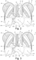
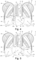
- the perforating device 5 comprises an abutment 33, movable to take an idle position, indicated in Fig. 2 , and an active position, illustrated for instance in Figs. 3-6 .
- the movement of the abutment 33 is indicated by the double arrow f33.
- the movement direction of the movable abutment 33 is in a plane containing the selection rotation axis 21A, around which the support beam 21 can be selectively rotate.
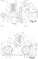
- movable abutment is indicated schematically, whilst Figs. 8 and 9 show an embodiment of the movable abutment 33 and of the members controlling the movement thereof according to the double arrow f33.
- the movable abutment 33 is formed by a wheel for reducing friction and rubbing with the contrast members, with which it co-acts, as detailed below.
- Abutment surfaces i.e. rest surfaces against the movable abutment 33, are integral with the support beam 21.
- the abutment surfaces are arranged around the selection rotation axis 21A in different angular positions corresponding to different angular positions of the support beam 21.
- the abutment surfaces are formed on a flange 47 integral with the support beam 21. More in particular, in the illustrated embodiment the flange 47 forms four abutment surfaces ( Figs. 2-6 ), indicated with 51A, 51B, 51C, 51D.
- the four abutment surfaces may be planes extending radially from a perimeter edge of the flange 47 towards the axis 21A of the support beam 21.
- the abutment surfaces may be formed, for example, by side walls of two notches 53, 55 provided along the edge of the flange 47.
- the four abutment surfaces 51A, 51B, 51C, 51D define four angular positions of the support beam 21. Each angular position is given by the contact of one of the four abutment surfaces 51A-51D with the movable abutment 33.
- the support beam 21 can take two angular working positions, whilst it can take two further angular working positions when the movable abutment 33 is in the notch 55.
- the movable abutment 33 can be brought into idle position outside the perimeter edge of the flange 47. The idle position is shown in Fig. 2 .
- the beam 21 can rotate so as to bring selectively one or the other of the notches 53 and 55 below the movable abutment 33, which then can be moved towards the selection rotation axis 21A to co-act selectively with one or the other of the abutment surfaces 51A, 51B, or with one or the other of the abutment surfaces 51C, 51D.
- the movable abutment 33 is in the notch 53 and the angular position of the flange 47 is such as to bring the abutment surface 51A against the movable abutment 33.
- the angular position of the flange 47 is such as to bring the abutment surface 51A against the movable abutment 33.
- one of the counter-blades 23 of the support beam 21 co-acts with the blades 31 of the rotating blade-holder 27, while no counter-blade co-acts with the blades 29 of the rotating blade-holder 25. Therefore, in this position the web material N is fed along the path F2 ( Fig. 1 ).
- Fig. 4 the support beam 21 has been rotated until it brings the abutment surface 51B against the movable abutment 33. In this position, one of the counter-blades 23 (different than that operative in the arrangement of Fig. 3 ) co-acts with the blades 29 of the rotating blade-holder 25 and the web material N passes along the path F1 in the nip between the blade-holder 25 and the support beam 21.
- a counter-blade 23 (different from the two counter-blades operative in the positions of Figs. 3 and 4 ) co-acts with the blades of the rotating blade-holder 25.
- a counter-blade 23 (different from the three counter-blades operative in the positions of Figs. 3 , 4 and 5 ) co-acts with the blades of the rotating blade-holder 27.
- the selection rotation movement of the support beam 21 is controlled by a second actuating device 61, shown in particular in Figs. 7 and 8 .
- the second actuating device 61 may simply comprise an adequately controlled electric motor.
- the second actuating device 61 comprises a first actuator, for example an electric motor or, more precisely, an electric gear motor 63.
- the reference number 64 indicates the reduction gear of the electric gear motor 63.
- the electric gear motor 63 may be mounted on a shaft 65 that is torsionally coupled, for instance through a locking device 66, to the support beam 21 and coaxial therewith.
- the second actuating device 61 further comprises a second actuator, for example a linear actuator, in particular a hydraulically or pneumatically controlled cylinder-piston actuator 69.
- the linear actuator 69 is connected through a bracket 70 to the side wall 41, and through a rod 69A to an arm 71 hinged on the shaft 65. Through the described kinematic coupling, the linear actuator 69 controls rotation movements, by a limited angle, of the shaft 65 and thus of the beam 21.
- the operation of the second actuating device 61 in combination with the first actuating device 43 is as follows. To set a desired angular working position for the support beam 21, firstly, if necessary, the movable abutment 33 is moved away from the flange 47. In this way, the support beam 21, and the flange 47 integral therewith, are rotated to the desired position, for example to the position of Fig. 2 , actuated by the gear motor 63. More precisely, the flange 47 and the support beam 21 may be brought to such an angular position that the movable abutment 33, once brought again towards the selection rotation axis 21A, is in the notch 53, in intermediate position between the abutment surfaces 51A, 51B.
- the linear actuator 69 extends or retracts, depending on whether the abutment surface 51A or the abutment surface 51B shall be activated. In this way, the shaft 69, the gear motor 63 and the support beam 21 are rotated around the selection rotation axis 21A until to achieve the desired position, for example the position of Fig. 3 or the position of Fig. 4 . In this step, the gear motor 63 acts as a body rigidly integral with the shaft 65.
- the web material N can be fed in the nip between the support beam 21 and the rotating blade-holder 27, to be perforated by means of one of the counter-blades 23 and the blades 31.
- the linear actuator 69 can quickly intervene to open the perforating device. This can be simply done by causing a clockwise rotation of the support beam 21, until the abutment surface 51A is moved away from the movable abutment 33. In this way, the paper accumulation can pass more easily through the perforation nip, making the recovery of the operative condition of the perforating device faster and safer.
- the positions of Figs. 5 and 6 are obtained by temporarily bringing the movable abutment 33 in idle position and rotating the support beam 21 through the gear motor 63, and then moving the movable abutment 33 again towards the selection rotation axis 21A, in intermediate position between the abutment surfaces 51C and 51D.
- the linear actuator 69 similarly to what described with reference to Figs. 3 and 4 , can bring the support beam 21 selectively to the position of Fig. 5 and to the position of Fig.
- the actuating devices 43 and 61 may interface a control unit 81, schematically indicated in Fig. 7 , that can have one or more user interfaces 83.
- the operator can set the desired type of perforation, corresponding to one or the other of the various perforating counter-blades 23.
- the control unit 81 automatically performs the operations of selecting the angular position of the flange 47 relative to the movable abutment 33 to bring the desired counter-blade into operation.
- the operation of selecting the counter-blade is simple and fast, and may not require manual operations, especially if it is not necessary to change the path (F1, F2) of the web material N.
- the support beam 21 may be provided with a reciprocating movement parallel to the selection rotation axis 21A and controlled for example by an electric motor 91 through an eccentric 93.
- the shaft 65 may be connected to the eccentric 93 through a joint 95 (see Figs. 7 and 8 ).
- the actuating device 61 comprises only the gear motor 63 and does not have the linear actuator 69.
- the gear motor 63 acts both to bring the support beam 21 into an angular working position, and to bring one of the respective abutment surfaces 51A, 51B, 51C, 51D against the movable abutment 33 with an adequate force by controlling the motor torque.
- Some of the methods for detecting malfunctions can be also used in the case of the embodiment illustrated in the figures. In this case it is also possible to detect the force necessary to keep the working position through a sensor associated with the linear actuator 69.
Landscapes
- Life Sciences & Earth Sciences (AREA)
- Forests & Forestry (AREA)
- Engineering & Computer Science (AREA)
- Mechanical Engineering (AREA)
- Perforating, Stamping-Out Or Severing By Means Other Than Cutting (AREA)
- Replacement Of Web Rolls (AREA)
- Electrical Discharge Machining, Electrochemical Machining, And Combined Machining (AREA)
- Lighting Device Outwards From Vehicle And Optical Signal (AREA)
Claims (15)
- Un dispositif de perforation (5) pour perforer un matériau en bande (N), comprenant :un premier porte-lame (25 ; 27) apte à tourner autour un premier axe de rotation respectif (25A ; 27A) et sur lequel au moins une première lame de perforation (29; 31) est montée ;une poutre de support (21), sur laquelle une pluralité de contre-lames (23) sont montées ; ladite poutre de support (21) étant réglable angulairement autour d'un axe de rotation de sélection (21) de cette poutre dans une pluralité de positions de travail angulaires, dans chaque position de travail angulaire l'une des contre-lames (23) étant en position de travail ;une butée mobile (33) apte à coopérer avec la poutre de support (21) ; la poutre de support (21) étant solidaire d'une pluralité de surfaces de butée (51A, 51B, 51C, 51D) aptes à coopérer sélectivement avec ladite butée mobile (33) ;un premier dispositif d'actionnement (43) apte à déplacer la butée mobile (33) entre une position active, où la butée mobile (33) coopère avec la poutre de support (21) et un position de repos où la butée mobile (33) est espacée de la poutre de support (21) ;un deuxième dispositif d'actionnement (61) apte à faire tourner la poutre de support (21) afin de l'agencer sélectivement dans l'une desdites positions de travail angulaires.
- Le dispositif de perforation (5) selon la revendication 1, dans lequel la butée mobile (33) est animée d'un mouvement (f33) de rapprochement et d'éloignement de l'axe de rotation de sélection (21A) sur la poutre de support (21).
- Le dispositif de perforation (5) selon la revendication 1 ou 2, dans lequel le premier dispositif d'actionnement (43) et le deuxième dispositif d'actionnement (61) sont connectés fonctionnellement à une unité de commande (81), prévue avec une interface (83) apte à recevoir des instructions pour ajuster la position angulaire de la poutre de support (21).
- Le dispositif de perforation (5) selon la revendication 1 ou 2, dans lequel la poutre de support (21) comprend un corps allongé suivant l'axe de rotation de sélection (21A) ; les contre-lames (23) s'étendant parallèlement à l'axe de rotation de sélection ou hélicoïdalement autour dudit axe de rotation de sélection ; et le corps allongé étant supporté à ses extrémités, sur des parois latérales d'une structure de support (41).
- Le dispositif de perforation (5) selon l'une ou plusieurs des revendications précédentes, dans lequel la pluralité de surfaces de butée (51A, 51B, 51C, 51D) sont formées par une bride (47) solidaire de la poutre de support (21).
- Le dispositif de perforation (5) selon la revendication 5, dans lequel les surfaces de butée (51A à 51D) sont formées par des évidements (53, 55) de la bride (47) s'étendant radialement depuis un bord périmétrique de la bride vers un axe central de la bride, chaque évidement (53, 55) formant de préférence deux surfaces de butées (51A à 51D) correspondant à deux positions angulaires de la poutre de support (21).
- Le dispositif de perforation (5) selon la revendication 5 ou 6, dans lequel la bride (47) est agencée entre un corps de la poutre de support et une tige de la poutre de support, par l'intermédiaire de laquelle la poutre de support (21) est montée sur une structure de support (41).
- Le dispositif de perforation (5) selon l'une ou plusieurs des revendications précédentes, dans lequel le deuxième dispositif d'actionnement (61) comprend un moteur électrique (63) apte à faire tourner sélectivement la poutre de support (21) autour de l'axe de rotation de sélection (21A).
- Le dispositif de perforation (5) selon l'une ou plusieurs des revendications précédentes, dans lequel le deuxième dispositif d'actionnement (61) comprend : un premier actionneur (63) apte à faire tourner la poutre de support (21) autour de l'axe de rotation de sélection (21A) afin d'agencer angulairement la poutre de support (21) dans l'un des plusieurs agencements angulaires alternatifs, à chacun desquels au moins une position de travail angulaire correspond ; un deux actionneur (69) apte à mettre la poutre de support (21) dans ladite ou lesdites position(s) de travail angulaire(s), où la butée mobile (33) est en contact avec une surface de butée respective (51A à 51D) solidaire de la poutre de support (21) ; deux positions de travail alternatives correspondant de préférence à au moins l'un desdits agencements angulaires alternatifs, dans le(s)quel(s) la poutre de support (21) peut être sélectivement mise par le deuxième actionneur (69) ; et le premier actionneur (63) étant de préférence un actionneur électrique, en particulier un moteur à engrenages électrique et le deuxième actionneur étant un actionneur linéaire (69), en particulier un actionneur à piston cylindrique.
- Le dispositif de perforation (5) selon la revendication 9, dans lequel le moteur électrique (63) est supporté sur un arbre (65) contraint en torsion à la poutre de support (21) et l'actionneur linéaire (69) est connecté cinématiquement à l'arbre (65) au moyen d'un mécanisme (71) convertissant le mouvement linéaire de l'actionneur linéaire (69) en un mouvement angulaire de l'arbre (65) et de la poutre de support (21).
- Le dispositif de perforation (5) selon l'une ou plusieurs des revendications précédentes, comprenant un dispositif de translation de va-et-vient (91, 93) apte à appliquer à la poutre de support (21) un mouvement de translation de va-et-vient parallèle à l'extension longitudinale de ladite poutre de support.
- Le dispositif de perforation (5) selon l'une ou plusieurs des revendications précédentes, comprenant un deuxième porte-lame (27 ; 25) qui est apte à tourner autour d'un deuxième axe de rotation respectif (27A, 25A) et sur lequel au moins une deuxième lame de perforation (31, 29) est montée ; dans lequel de préférence la poutre de support (21) comprend : au moins deux contre-lames (23) aptes à coopérer avec ladite ou lesdites première(s) lame(s) de perforation (29, 31) portée(s) par le premier porteur de lame (25; 27) ; et au moins deux contre-lames (23) aptes à coopérer avec ladite ou lesdites deuxième(s) lame(s) de perforation (31 ; 29) portée(s) par le deuxième porte-lame (27 ; 25) ; et dans lequel de préférence la poutre de support (21) comprend au moins une première paire de butées (51A, 51B ; 51C, 51D) connectées rigidement à la poutre de support (21) et associées à une première position angulaire de la poutre de support, et une deuxième paire de butées (51C, 51D ; 51A, 51B) rigidement connectées à la poutre de support (21) et associées à une deuxième position angulaire de la poutre de support ; chacune desdites paires de butée formant une position de travail où la contre-lame (23) de la poutre de support (21) coopère avec la ou les lame(s) de perforation (29 ; 31) du premier support de lame (25 ; 27) et une position de travail où une contre-lame (23) de la poutre de support (21) coopère avec la ou les lame(s) de perforation (31; 29) du deuxième porte-lame (27 ; 25).
- Une machine de conversion (1) comprenant des organes de conversion (3) pour convertir un matériau en bande (N) et le dispositif de perforation (5) selon l'une ou plusieurs des revendications précédentes.
- La machine de conversion (1) selon la revendication 13, configurée comme une rembobineuse, dans laquelle lesdits organes de conversion (3) comprennent des organes d'enroulement (3A, 3B, 3C) aptes à produire des rouleaux (R) de matériau en bande enroulée (N).
- Un procédé de perforation d'un matériau en bande continue (N) le long de lignes de perforation perpendiculaires à une extension longitudinale du matériau en bande (N), avec le dispositif de perforation selon l'une ou plusieurs des revendications 1 à12, comprenant les étapes suivantes consistant à :régler sur un type de perforation ;au moyen d'un agencement d'actionneurs, positionner angulairement la poutre de support (21) dans une position de travail angulaire, où la contre-lame (23) de la poutre de support (21) est dans une position de travail apte à coopérer avec la ou les lame(s) de perforation (29, 31) dudit ou desdits porte-lame (25, 27) ;faire avancer le matériau en bande jusqu'à un espace de perforation entre la poutre de support (21) et le porte-lame tournant (25 ; 27) de façon à produire des lignes de perforation transversales au moyen de la contre-lame (23) sélectionnée et de ladite ou lesdites lame(s) de perforation tournante(s).
Applications Claiming Priority (2)
| Application Number | Priority Date | Filing Date | Title |
|---|---|---|---|
| IT102018000010637A IT201800010637A1 (it) | 2018-11-28 | 2018-11-28 | Dispositivo perforatore e macchina di trasformazione comprendente detto dispositivo |
| PCT/IB2019/060218 WO2020110020A1 (fr) | 2018-11-28 | 2019-11-27 | Dispositif de perforation et machine de conversion comprenant ledit dispositif |
Publications (3)
| Publication Number | Publication Date |
|---|---|
| EP3887103A1 EP3887103A1 (fr) | 2021-10-06 |
| EP3887103B1 true EP3887103B1 (fr) | 2025-01-01 |
| EP3887103C0 EP3887103C0 (fr) | 2025-01-01 |
Family
ID=65685874
Family Applications (1)
| Application Number | Title | Priority Date | Filing Date |
|---|---|---|---|
| EP19831887.5A Active EP3887103B1 (fr) | 2018-11-28 | 2019-11-27 | Dispositif de perforation und machine avec le dispositif |
Country Status (5)
| Country | Link |
|---|---|
| US (1) | US12275159B2 (fr) |
| EP (1) | EP3887103B1 (fr) |
| CN (1) | CN113226676B (fr) |
| IT (1) | IT201800010637A1 (fr) |
| WO (1) | WO2020110020A1 (fr) |
Families Citing this family (2)
| Publication number | Priority date | Publication date | Assignee | Title |
|---|---|---|---|---|
| IT202200016767A1 (it) * | 2022-08-05 | 2024-02-05 | Ot Lucca S R L | Macchina interfogliatrice, impianto e metodo per il cambio cut-off |
| EP4713180A1 (fr) * | 2023-06-23 | 2026-03-25 | BW Converting, Inc. | Unité de perforateur et indexeur pour unité de perforateur |
Citations (1)
| Publication number | Priority date | Publication date | Assignee | Title |
|---|---|---|---|---|
| WO2000006351A1 (fr) * | 1998-07-27 | 2000-02-10 | Fabio Perini S.P.A. | Perforateur pour materiaux du type en bande, dote de moyens de modification de l'intervalle entre des lignes consecutives de perforations |
Family Cites Families (16)
| Publication number | Priority date | Publication date | Assignee | Title |
|---|---|---|---|---|
| US2782853A (en) * | 1955-08-08 | 1957-02-26 | American Viscose Corp | Precision fiber cutter |
| US2990741A (en) * | 1958-10-06 | 1961-07-04 | American Viscose Corp | Control system for rotary cutter |
| DE1215495B (de) * | 1963-12-23 | 1966-04-28 | Winkler Richard | Vorrichtung zur Erzeugung profilierter Aussen- und Innenschnitte an bewegten Bahnen oder Einzelzuschnitten aus Papier od. dgl., insbesondere zum Herstellen von Briefumschlaegen, Flachbeuteln od. dgl. |
| US3750510A (en) * | 1971-05-04 | 1973-08-07 | Frastan Hollinwood Ltd | Cutting apparatus for paper and like webs |
| DE3202264C2 (de) * | 1982-01-25 | 1984-04-12 | Siemens AG, 1000 Berlin und 8000 München | Anordnung zum Antrieb einer Papierabschneideeinrichtung |
| IT1233145B (it) * | 1989-02-07 | 1992-03-14 | Perini Finanziaria Spa | Congegno perforatore per perforazioni trasversali di materiale cartaceo nastriforme |
| IT1247331B (it) * | 1991-04-03 | 1994-12-12 | Perini Fabio Spa | Dispositivo perforatore per nastri di carta o simili, con movimento alternativo di traslazione della contro-lama. |
| DE69906036T2 (de) * | 1999-05-06 | 2004-01-22 | Casmatic S.P.A. | Folienschneideinrichtung insbesondere für eine Wickelmaschine |
| US20060266179A1 (en) * | 2005-05-16 | 2006-11-30 | Koyo Jidoki Co., Ltd. | Rotary cutter and method for adjusting fixing angle of stationary blade in rotary cutter |
| DE502006007084D1 (de) * | 2006-03-22 | 2010-07-15 | Hunkeler Ag | Querschneidevorrichtung und Verfahren zum Betrieb einer solchen Querschneidevorrichtung |
| DE102006051359A1 (de) * | 2006-10-27 | 2008-04-30 | Khs Ag | Schneidwerk für ein Etikettieraggregat sowie Etikettieraggregat mit einem solchen Schneidwerk |
| WO2014135276A1 (fr) * | 2013-03-08 | 2014-09-12 | Bobst Mex Sa | Agencement de découpe et d'éjection des déchets, cassette, unité et machine ainsi équipée |
| EP3243614B1 (fr) * | 2016-05-09 | 2019-10-09 | Sidel Participations | Unité de coupe pour une machine d'étiquetage |
| IT201700011567A1 (it) * | 2017-02-02 | 2018-08-02 | Futura Spa | procedimento ed apparecchiatura per il controllo della corretta esecuzione delle linee di pre-taglio. |
| JP7386605B2 (ja) * | 2017-11-30 | 2023-11-27 | ミュラー・マルティニ・ホルディング・アクチエンゲゼルシヤフト | ペーパーウェブの切断又は穿孔をするための装置及び方法 |
| US10857690B2 (en) * | 2018-09-11 | 2020-12-08 | The Procter & Gamble Company | Method and apparatus for adjusting and maintaining a position of a cutting surface of a perforating apparatus |
-
2018
- 2018-11-28 IT IT102018000010637A patent/IT201800010637A1/it unknown
-
2019
- 2019-11-27 CN CN201980086713.5A patent/CN113226676B/zh active Active
- 2019-11-27 WO PCT/IB2019/060218 patent/WO2020110020A1/fr not_active Ceased
- 2019-11-27 EP EP19831887.5A patent/EP3887103B1/fr active Active
- 2019-11-27 US US17/297,573 patent/US12275159B2/en active Active
Patent Citations (1)
| Publication number | Priority date | Publication date | Assignee | Title |
|---|---|---|---|---|
| WO2000006351A1 (fr) * | 1998-07-27 | 2000-02-10 | Fabio Perini S.P.A. | Perforateur pour materiaux du type en bande, dote de moyens de modification de l'intervalle entre des lignes consecutives de perforations |
Also Published As
| Publication number | Publication date |
|---|---|
| CN113226676B (zh) | 2022-09-09 |
| WO2020110020A1 (fr) | 2020-06-04 |
| US12275159B2 (en) | 2025-04-15 |
| CN113226676A (zh) | 2021-08-06 |
| EP3887103A1 (fr) | 2021-10-06 |
| BR112021010097A2 (pt) | 2021-08-24 |
| EP3887103C0 (fr) | 2025-01-01 |
| IT201800010637A1 (it) | 2020-05-28 |
| US20220024062A1 (en) | 2022-01-27 |
Similar Documents
| Publication | Publication Date | Title |
|---|---|---|
| CN109454688B (zh) | 连接切口组件和瓦楞板设施 | |
| EP2655227B1 (fr) | Machine d'enroulement et procédé d'enroulement | |
| EP2694414B1 (fr) | Machine de rembobinage et procédé de production de rondins de matériau en bande | |
| EP3887103B1 (fr) | Dispositif de perforation und machine avec le dispositif | |
| JPH09202499A (ja) | 渦巻き状巻取りの方法と装置 | |
| JP2009102784A (ja) | 不織布加工装置及び方法 | |
| US20100011924A1 (en) | Corrugating apparatus | |
| US20100101386A1 (en) | Variable signature length web cutting apparatus | |
| US20040173068A1 (en) | Method for cutting continuous sheet | |
| JP5835901B2 (ja) | コルゲートマシンにおけるトリム処理方法,コルゲートマシン及びエッジカット装置 | |
| EP1452283B1 (fr) | Méthode pour la change de format dans la coupe longitudinel d'un matériel en feuille avec le bord ininterrompu | |
| EP2871049B1 (fr) | Appareil de découpe et d'enroulement d'un matériau de carcasse pour pneus | |
| EP2733098B1 (fr) | Unité découpeuse-enrouleuse d'une ligne de production de bande de fibre | |
| EP2067584A1 (fr) | Dispositif d'enroulement ayant des moyens de perforation ainsi que procédé | |
| WO1999057050A1 (fr) | Appareil et procede de coupe transversale pour un materiau de type bande continue, et coupeuse en feuilles | |
| EP0424423A1 (fr) | Dispositif pour fixer une nappe de tissu souple sur un nouvel axe d'enroulement vide. | |
| BR112021010097B1 (pt) | Dispositivo de perfuração e máquina de conversão que compreende o dito dispositivo | |
| US20240336450A1 (en) | Guide system to guide paper webs | |
| US20240317532A1 (en) | Guide system to guide paper webs | |
| EP3532417B1 (fr) | Machine et procédé pour enrouler des bandes de matériau en bande pourvus de moyens permettant la coupe transversale des bandes à la fin de l'enroulement | |
| US317612A (en) | baeton | |
| US416829A (en) | Trimming and slitting machine | |
| CN223704703U (zh) | 一种分切机的切割轴自动调节装置 | |
| JP4728366B2 (ja) | スリッター装置及び輪転機 | |
| SU153274A1 (fr) |
Legal Events
| Date | Code | Title | Description |
|---|---|---|---|
| STAA | Information on the status of an ep patent application or granted ep patent |
Free format text: STATUS: UNKNOWN |
|
| STAA | Information on the status of an ep patent application or granted ep patent |
Free format text: STATUS: THE INTERNATIONAL PUBLICATION HAS BEEN MADE |
|
| PUAI | Public reference made under article 153(3) epc to a published international application that has entered the european phase |
Free format text: ORIGINAL CODE: 0009012 |
|
| STAA | Information on the status of an ep patent application or granted ep patent |
Free format text: STATUS: REQUEST FOR EXAMINATION WAS MADE |
|
| 17P | Request for examination filed |
Effective date: 20210525 |
|
| AK | Designated contracting states |
Kind code of ref document: A1 Designated state(s): AL AT BE BG CH CY CZ DE DK EE ES FI FR GB GR HR HU IE IS IT LI LT LU LV MC MK MT NL NO PL PT RO RS SE SI SK SM TR |
|
| DAV | Request for validation of the european patent (deleted) | ||
| DAX | Request for extension of the european patent (deleted) | ||
| RAP3 | Party data changed (applicant data changed or rights of an application transferred) |
Owner name: KOERBER TISSUE S.P.A. |
|
| P01 | Opt-out of the competence of the unified patent court (upc) registered |
Effective date: 20230530 |
|
| RAP3 | Party data changed (applicant data changed or rights of an application transferred) |
Owner name: VALMET TISSUE CONVERTING S.P.A. |
|
| GRAP | Despatch of communication of intention to grant a patent |
Free format text: ORIGINAL CODE: EPIDOSNIGR1 |
|
| STAA | Information on the status of an ep patent application or granted ep patent |
Free format text: STATUS: GRANT OF PATENT IS INTENDED |
|
| INTG | Intention to grant announced |
Effective date: 20240705 |
|
| GRAS | Grant fee paid |
Free format text: ORIGINAL CODE: EPIDOSNIGR3 |
|
| GRAA | (expected) grant |
Free format text: ORIGINAL CODE: 0009210 |
|
| STAA | Information on the status of an ep patent application or granted ep patent |
Free format text: STATUS: THE PATENT HAS BEEN GRANTED |
|
| AK | Designated contracting states |
Kind code of ref document: B1 Designated state(s): AL AT BE BG CH CY CZ DE DK EE ES FI FR GB GR HR HU IE IS IT LI LT LU LV MC MK MT NL NO PL PT RO RS SE SI SK SM TR |
|
| REG | Reference to a national code |
Ref country code: GB Ref legal event code: FG4D |
|
| REG | Reference to a national code |
Ref country code: DE Ref legal event code: R096 Ref document number: 602019064353 Country of ref document: DE |
|
| REG | Reference to a national code |
Ref country code: CH Ref legal event code: EP |
|
| REG | Reference to a national code |
Ref country code: IE Ref legal event code: FG4D |
|
| P04 | Withdrawal of opt-out of the competence of the unified patent court (upc) registered |
Free format text: CASE NUMBER: APP_4516/2025 Effective date: 20250128 |
|
| U01 | Request for unitary effect filed |
Effective date: 20250124 |
|
| U07 | Unitary effect registered |
Designated state(s): AT BE BG DE DK EE FI FR IT LT LU LV MT NL PT RO SE SI Effective date: 20250130 |
|
| PG25 | Lapsed in a contracting state [announced via postgrant information from national office to epo] |
Ref country code: PL Free format text: LAPSE BECAUSE OF FAILURE TO SUBMIT A TRANSLATION OF THE DESCRIPTION OR TO PAY THE FEE WITHIN THE PRESCRIBED TIME-LIMIT Effective date: 20250101 |
|
| PG25 | Lapsed in a contracting state [announced via postgrant information from national office to epo] |
Ref country code: ES Free format text: LAPSE BECAUSE OF FAILURE TO SUBMIT A TRANSLATION OF THE DESCRIPTION OR TO PAY THE FEE WITHIN THE PRESCRIBED TIME-LIMIT Effective date: 20250101 |
|
| PG25 | Lapsed in a contracting state [announced via postgrant information from national office to epo] |
Ref country code: IS Free format text: LAPSE BECAUSE OF FAILURE TO SUBMIT A TRANSLATION OF THE DESCRIPTION OR TO PAY THE FEE WITHIN THE PRESCRIBED TIME-LIMIT Effective date: 20250501 Ref country code: NO Free format text: LAPSE BECAUSE OF FAILURE TO SUBMIT A TRANSLATION OF THE DESCRIPTION OR TO PAY THE FEE WITHIN THE PRESCRIBED TIME-LIMIT Effective date: 20250401 |
|
| PG25 | Lapsed in a contracting state [announced via postgrant information from national office to epo] |
Ref country code: HR Free format text: LAPSE BECAUSE OF FAILURE TO SUBMIT A TRANSLATION OF THE DESCRIPTION OR TO PAY THE FEE WITHIN THE PRESCRIBED TIME-LIMIT Effective date: 20250101 |
|
| PG25 | Lapsed in a contracting state [announced via postgrant information from national office to epo] |
Ref country code: GR Free format text: LAPSE BECAUSE OF FAILURE TO SUBMIT A TRANSLATION OF THE DESCRIPTION OR TO PAY THE FEE WITHIN THE PRESCRIBED TIME-LIMIT Effective date: 20250402 |
|
| PG25 | Lapsed in a contracting state [announced via postgrant information from national office to epo] |
Ref country code: CZ Free format text: LAPSE BECAUSE OF FAILURE TO SUBMIT A TRANSLATION OF THE DESCRIPTION OR TO PAY THE FEE WITHIN THE PRESCRIBED TIME-LIMIT Effective date: 20250101 |
|
| PG25 | Lapsed in a contracting state [announced via postgrant information from national office to epo] |
Ref country code: SM Free format text: LAPSE BECAUSE OF FAILURE TO SUBMIT A TRANSLATION OF THE DESCRIPTION OR TO PAY THE FEE WITHIN THE PRESCRIBED TIME-LIMIT Effective date: 20250101 |
|
| PG25 | Lapsed in a contracting state [announced via postgrant information from national office to epo] |
Ref country code: SK Free format text: LAPSE BECAUSE OF FAILURE TO SUBMIT A TRANSLATION OF THE DESCRIPTION OR TO PAY THE FEE WITHIN THE PRESCRIBED TIME-LIMIT Effective date: 20250101 |
|
| U20 | Renewal fee for the european patent with unitary effect paid |
Year of fee payment: 7 Effective date: 20250925 |
|
| PLBE | No opposition filed within time limit |
Free format text: ORIGINAL CODE: 0009261 |
|
| STAA | Information on the status of an ep patent application or granted ep patent |
Free format text: STATUS: NO OPPOSITION FILED WITHIN TIME LIMIT |
|
| 26N | No opposition filed |
Effective date: 20251002 |