EP3888576A1 - Marknagel zur applikation von pharmazeutischen fluiden - Google Patents
Marknagel zur applikation von pharmazeutischen fluiden Download PDFInfo
- Publication number
- EP3888576A1 EP3888576A1 EP20167055.1A EP20167055A EP3888576A1 EP 3888576 A1 EP3888576 A1 EP 3888576A1 EP 20167055 A EP20167055 A EP 20167055A EP 3888576 A1 EP3888576 A1 EP 3888576A1
- Authority
- EP
- European Patent Office
- Prior art keywords
- intramedullary nail
- reservoir
- fluid
- conduit means
- pharmaceutical
- Prior art date
- Legal status (The legal status is an assumption and is not a legal conclusion. Google has not performed a legal analysis and makes no representation as to the accuracy of the status listed.)
- Granted
Links
Images



Classifications
-
- A—HUMAN NECESSITIES
- A61—MEDICAL OR VETERINARY SCIENCE; HYGIENE
- A61B—DIAGNOSIS; SURGERY; IDENTIFICATION
- A61B17/00—Surgical instruments, devices or methods
- A61B17/56—Surgical instruments or methods for treatment of bones or joints; Devices specially adapted therefor
- A61B17/58—Surgical instruments or methods for treatment of bones or joints; Devices specially adapted therefor for osteosynthesis, e.g. bone plates, screws or setting implements
- A61B17/68—Internal fixation devices, including fasteners and spinal fixators, even if a part thereof projects from the skin
- A61B17/72—Intramedullary devices, e.g. pins or nails
-
- A—HUMAN NECESSITIES
- A61—MEDICAL OR VETERINARY SCIENCE; HYGIENE
- A61B—DIAGNOSIS; SURGERY; IDENTIFICATION
- A61B17/00—Surgical instruments, devices or methods
- A61B17/34—Trocars; Puncturing needles
- A61B17/3415—Trocars; Puncturing needles for introducing tubes or catheters, e.g. gastrostomy tubes, drain catheters
-
- A—HUMAN NECESSITIES
- A61—MEDICAL OR VETERINARY SCIENCE; HYGIENE
- A61B—DIAGNOSIS; SURGERY; IDENTIFICATION
- A61B17/00—Surgical instruments, devices or methods
- A61B17/34—Trocars; Puncturing needles
- A61B17/3472—Trocars; Puncturing needles for bones, e.g. intraosseus injections
-
- A—HUMAN NECESSITIES
- A61—MEDICAL OR VETERINARY SCIENCE; HYGIENE
- A61B—DIAGNOSIS; SURGERY; IDENTIFICATION
- A61B17/00—Surgical instruments, devices or methods
- A61B17/56—Surgical instruments or methods for treatment of bones or joints; Devices specially adapted therefor
- A61B17/58—Surgical instruments or methods for treatment of bones or joints; Devices specially adapted therefor for osteosynthesis, e.g. bone plates, screws or setting implements
- A61B17/68—Internal fixation devices, including fasteners and spinal fixators, even if a part thereof projects from the skin
- A61B17/72—Intramedullary devices, e.g. pins or nails
- A61B17/7233—Intramedullary devices, e.g. pins or nails with special means of locking the nail to the bone
-
- A—HUMAN NECESSITIES
- A61—MEDICAL OR VETERINARY SCIENCE; HYGIENE
- A61B—DIAGNOSIS; SURGERY; IDENTIFICATION
- A61B17/00—Surgical instruments, devices or methods
- A61B2017/00477—Coupling
-
- A—HUMAN NECESSITIES
- A61—MEDICAL OR VETERINARY SCIENCE; HYGIENE
- A61B—DIAGNOSIS; SURGERY; IDENTIFICATION
- A61B17/00—Surgical instruments, devices or methods
- A61B17/56—Surgical instruments or methods for treatment of bones or joints; Devices specially adapted therefor
- A61B2017/561—Implants with special means for releasing a drug
-
- A—HUMAN NECESSITIES
- A61—MEDICAL OR VETERINARY SCIENCE; HYGIENE
- A61M—DEVICES FOR INTRODUCING MEDIA INTO, OR ONTO, THE BODY; DEVICES FOR TRANSDUCING BODY MEDIA OR FOR TAKING MEDIA FROM THE BODY; DEVICES FOR PRODUCING OR ENDING SLEEP OR STUPOR
- A61M5/00—Devices for bringing media into the body in a subcutaneous, intra-vascular or intramuscular way; Accessories therefor, e.g. filling or cleaning devices, arm-rests
- A61M5/14—Infusion devices, e.g. infusing by gravity; Blood infusion; Accessories therefor
- A61M5/168—Means for controlling media flow to the body or for metering media to the body, e.g. drip meters, counters ; Monitoring media flow to the body
- A61M5/16877—Adjusting flow; Devices for setting a flow rate
- A61M5/16881—Regulating valves
Definitions
- the invention relates to an intramedullary nail for the application of a pharmaceutical fluid, comprising a fluid-conducting first line means running axially in the intramedullary nail, which can be connected to a first reservoir for the pharmaceutical fluid, and at least one passage which connects the first line means to an outer surface of the intramedullary nail in a fluid-conducting manner.
- the invention further relates to a method for treating bone fractures and for applying a pharmaceutical fluid to the area of a bone canal by means of an intramedullary nail.
- intramedullary nails has proven itself for decades for the surgical treatment of both open and closed bone fractures, in particular for the treatment of bone fractures of large tubular bones.
- an intramedullary nail is inserted and fixed in the bone canal, which remains within the bone canal at least until the bone fracture heals.
- Bone fractures can contaminate the bone tissue with microorganisms.
- the infections triggered in this way such as osteitis, in particular osteomyelitis, are very serious diseases.
- To treat microbial infections, local administration of antibiotics is common after surgical debridement of the infected bone tissue.
- intramedullary nails with a perforated intramedullary nail body, by means of which, after implantation, various pharmaceutical fluids, such as antiseptic active ingredient solutions, can be applied locally to the infected bone tissue via a supply line from the outside.
- various pharmaceutical fluids such as antiseptic active ingredient solutions
- Such intramedullary nails are for example in the U.S. 5,681,289 A , the CN 2857862 Y and the CN 201370624 Y described.
- An antiseptic active ingredient solution can escape through ducts in the corresponding intramedullary nails and reach the infected bone tissue.
- a disadvantage of the intramedullary nails described is an unwanted accumulation of the active substance contained in the pharmaceutical fluid in the patient's body, which is caused by the high application pressure required when the fluid is pressed into the bone canal.
- antibiotics such as aminoglycoside antibiotics
- high systemic concentrations of antibiotics can cause damage to the patient, such as kidney damage and damage to the auditory nerve.
- the build-up of pressure caused by the application increases the risk of embolism.
- the invention is based on the aim of providing intramedullary nails which are able to rinse the interior of bones, in particular tubular bones, with pharmaceutical fluids of any composition, in particular with antiseptic active ingredient solutions, such as, for example, antibiotic-containing active ingredient solutions.
- the pharmaceutical fluid should be able to be supplied to the intramedullary nail from a reservoir arranged outside the patient's body and, at the same time, side effects such as the accumulation of the supplied active ingredient in the patient's body and the formation of embolisms, in particular fat embolisms, should be avoided.
- the aim is also to reliably distribute the active ingredient solution over the interior of the bones and at the same time to ensure high mechanical stability of the intramedullary nails and secure fixation of the same in the bone guarantee.
- the intramedullary nails should enable a safe and controllable rinsing of the interior of a bone without contamination or clogging of the intramedullary nails, in particular through penetration of bone tissue into the intramedullary nails.
- range specifications also include the values specified as limits.
- An indication of the type “in the range from X to Y” in relation to a variable A consequently means that A can assume the values X, Y and values between X and Y. Areas delimited on one side of the type "up to Y" for a size A accordingly mean Y as a value and less than Y.
- a first object of the invention relates to an intramedullary nail for the application of a pharmaceutical fluid, comprising a fluid-conducting first conduit means which runs axially in the intramedullary nail and which can be connected to a first reservoir for the pharmaceutical fluid and at least one passage which fluidly connects the first conduit to an outer surface of the intramedullary nail, characterized in that a fluid-conducting second conduit means connects the outer surface to a second reservoir in such a way as to convey the pharmaceutical fluid between the first reservoir and the second reservoir.
- An intramedullary nail is an intramedullary splint in the treatment of a bone fracture, in particular a long bone, which breaks the bone until it heals Stabilized bone fracture.
- a bone fracture in particular a long bone
- the terms "reamed” and “not reamed” referring to the method of implantation of the intramedullary nails.
- the entire medullary canal of the long bone is drilled out and then the intramedullary nail is driven into the drilled bone canal. Mechanical locking to fix the intramedullary nail within the bone canal is not mandatory.
- Non-reamed intramedullary nails are more massive, but thinner than reamed intramedullary nails, and fixation with locking screws is usually required.
- the intramedullary nail according to the invention can be used both as a reamed intramedullary nail and as a non-reamed intramedullary nail, use as a reamed intramedullary nail being preferred.
- the intramedullary nail according to the invention is used to apply a pharmaceutical fluid for the treatment of infected bone tissue, in particular for application within the bone canal of the bone, over a period of several days to weeks.
- a pharmaceutical fluid contains at least one pharmaceutical active ingredient.
- the pharmaceutical fluid is aqueous or non-aqueous solutions or suspensions of pharmaceutical active ingredients.
- the pharmaceutical fluid is a solution which contains at least one antibiotic, at least one chemotherapeutic agent and / or at least one antimycotic agent.
- the pharmaceutical fluids contain at least one disinfecting component.
- pharmaceutical fluids also include gases, gas mixtures and solutions of gases in liquids, such as, for example, water.
- the intramedullary nail has a first line means and a second line means.
- a conduit means all elements which can connect two structures to one another in a fluid-conducting manner. Examples of such elements are tubular, hose-like or channel-like connections.
- the first conduit means and / or the second conduit means can, for example, have an internal cross section of 0.5 mm 2 to 5 mm 2 , preferably 1 mm 2 to 4 mm 2 .
- the first conduit means and / or the second conduit means can each have a sieve or consist of a sieve.
- the first conduit means runs at least partially axially within the intramedullary nail.
- the axial course of the first conduit means within the intramedullary nail can be designed in different ways. Because of the ease of manufacture, the first conduit means preferably runs at least partially parallel to the longitudinal axis of the intramedullary nail.
- the path that the first conduit means runs axially within the intramedullary nail can be designed to be of different lengths.
- the first conduit means can run axially through 1-100% of a total length of the intramedullary nail.
- the first conduit means can run axially through at least 1%, 10%, 70%, 80% of the total length of the intramedullary nail, for example.
- the first conduit means can run axially through a maximum of 100%, 95%, 90% or 85% of the total length of the intramedullary nail.
- the intramedullary nail can be connected in a fluid-conducting manner to a first reservoir via the first conduit means and to a second reservoir for a pharmaceutical fluid via the second conduit means.
- a reservoir is understood to mean all containers which are suitable for providing and / or receiving the pharmaceutical fluid. Examples of reservoirs include bags, syringes, plungers, balloons, canisters and ampoules, with bags, balloons and syringes being preferred.
- a reservoir for receiving the pharmaceutical fluid it can also be a bag, a vessel or some other type of collecting container, which does not have to be structurally connected to the first line means or the second line means, but is suitable for that from the first To collect line means or the second line means exiting pharmaceutical fluid.
- the reservoir receiving the pharmaceutical fluid can also be a space or a floor of a space into which the pharmaceutical fluid emerging from the first conduit means or the second conduit means is discharged or onto which the, in this case liquid, pharmaceutical fluid flows or drips.
- the first conduit means is fluidly connected to an outer surface of the intramedullary nail via at least one passage, the outer surface representing the surface of the intramedullary nail which is in physical contact with the patient's bone tissue.
- the at least one passage is designed as at least one perforation in the intramedullary nail which connects the first conduit means to the outer surface in a fluid-conducting manner.
- the feedthrough can have an internal cross section of 0.5 mm 2 to 5 mm 2 , preferably 1 mm 2 to 4 mm 2 .
- the at least one passage can have a sieve, consist of a sieve or a closure, such as a flap, which only opens when the pharmaceutical fluid is conveyed through the at least one passage, but otherwise remains closed and thus a Ingrown tissue, and thus clogging of the at least one passage, is prevented.
- a sieve consist of a sieve or a closure, such as a flap
- the first reservoir can be fluidly connected to the second reservoir via the first conduit means, the at least one passage, the outer surface of the intramedullary nail and the second conduit means in order to convey the pharmaceutical fluid between the first reservoir and the second reservoir, so that the pharmaceutical fluid can the infected bone tissue surrounding the intramedullary nail can be applied.
- the pharmaceutical fluid can be conveyed from the first reservoir via the first conduit means, the at least one passage, the outer surface of the intramedullary nail and the second conduit means into the second reservoir.
- the pharmaceutical fluid can be conveyed from the second reservoir via the second conduit means, the outer surface of the intramedullary nail, the at least one passage and the first conduit means into the first reservoir.
- the pharmaceutical fluid comes into contact with the patient's bone tissue via the outer surface of the intramedullary nail and thus allows the active ingredient contained in the pharmaceutical fluid to be applied to combat infections in the area of the bone fracture.
- the pharmaceutical fluid does not remain in the area of the infected bone tissue, but can instead be discharged into the first reservoir or the second reservoir.
- a continued supply of the pharmaceutical fluid does not generate any pressure build-up due to the fluid remaining in the bone canal, as a result of which an undesired increased introduction of the active substance into the bloodstream of the patient is prevented. This prevents the active substance from accumulating in the patient and also reduces the risk of embolism.
- first line means comprises a first connection for fluid-conducting connection to the first reservoir and the second line means comprises a second connection for fluid-conducting connection to the second reservoir, the first connection and the second connection at a first end of the intramedullary nail are arranged.
- connection is to be understood as a structural unit which allows the conduit and reservoir to be connected in a fluid-conducting manner.
- the connection is designed as a grommet, via which the conduit means can be connected to the reservoir in a fluid-conducting manner by means of a hose.
- the connection is formed as a thread which can be connected to the reservoir in a fluid-conducting manner via a corresponding counterpart.
- the connection forms a flange connection with the reservoir.
- the connection forms a fluid-conducting connection with the reservoir via a hose coupling, wherein the connection can have the coupling or the nipple of the hose coupling.
- the first connection and the second connection are arranged together at a first end of the intramedullary nail, so that the supply and discharge of the pharmaceutical fluid into and out of the bone canal can take place at the same end of the bone.
- the first connection and the second connection are preferably located at the end of the intramedullary nail which faces the opening in the bone provided for the implantation of the intramedullary nail.
- the first connection and the second connection form a common structural element, such as a common grommet, which allows the use of a double hose system for feeding and discharging the pharmaceutical fluid into or out of the intramedullary nail.
- One embodiment of the intramedullary nail is characterized in that the at least one passage is arranged on a second end of the intramedullary nail opposite the first end.
- the first conduit means thus extends from the first end of the intramedullary nail, where the first connection is located, to the second end of the intramedullary nail, at which the feedthrough connects the first conduit means to the outer surface of the intramedullary nail in a fluid-conducting manner.
- the first conduit means preferably extends axially over 70-100%, more preferably over 80-100%, even more preferably over 85-95% of the total length of the intramedullary nail.
- the second conduit means is designed in such a way, for example as at least one channel into the intramedullary nail, that the pharmaceutical fluid is diverted from the outer surface of the intramedullary nail at the first end of the intramedullary nail.
- the pharmaceutical fluid is preferably at least over 60-100%, preferably 70-100%, more preferably between 80-95% of the total length of the intramedullary nail along the outer surface, starting with the at least one passage, before it is conveyed by means of the dissipative design of the second Conduction means from the outer surface is promoted.
- the intramedullary nail allows large-area treatment of infected bone tissue.
- the pharmaceutical fluid can be guided in different ways along the outer surface of the intramedullary nail.
- the second conduit means is at least partially designed as at least one axially extending groove in the outer surface.
- the pharmaceutical fluid can be conveyed safely through the at least one groove, in larger quantities and without the risk of clogging, with wetting of the outer surface along the groove ensuring effective control of an infection.
- the second conduit means is preferably designed as a plurality of, for example two to ten, axially extending grooves which are distributed radially over the outer surface of the intramedullary nail.
- the at least one axially extending groove can be configured differently.
- the at least one axially extending groove runs in wave-shaped deflections along the outer surface.
- the at least one groove runs helically along the outer surface. Due to the ease of manufacture, the at least one axially extending groove runs essentially parallel to the longitudinal axis of the intramedullary nail.
- the at least one groove can extend along the longitudinal axis of the intramedullary nail of different lengths.
- the at least one groove can extend over 5-100%, preferably over 50-100%, more preferably over 70-95% of the total length of the intramedullary nail along the outer surface.
- the at least one passage and the second conduit means can be connected to one another in a fluid-conducting manner in different ways.
- the at least one passage and the second conduit means in particular in the form of at least one axially extending groove in the outer surface, are not connected to one another in a fluid-conducting manner, but only via the outer surface of the intramedullary nail.
- One embodiment of the intramedullary nail is characterized in that the at least one axially extending groove is connected to the at least one passage in a direct fluid-conducting manner, without the pharmaceutical fluid having to be conveyed via the outer surface of the intramedullary nail. This further reduces the risk of an unwanted pressure build-up when conveying the pharmaceutical fluid between the first reservoir and the second reservoir.
- One embodiment of the intramedullary nail is characterized in that the second conduit means is designed as two to six, in particular four, axially extending grooves in the outer surface and the intramedullary nail has the same number of passages, with one groove each having a passage directly conducting fluid connected to each other.
- the intramedullary nail allows the pharmaceutical fluid to be conveyed both from the first reservoir into the second reservoir and from the second reservoir into the first reservoir.
- an embodiment of the intramedullary nail is characterized in that the first line means has a first check valve. In this way it is possible to check which parts of the intramedullary nail are contaminated with pharmaceutical fluid which has already come into contact with bone tissue. In addition, this allows the direction of flow of the pharmaceutical fluid through the intramedullary nail to be selected, which brings with it the lower risk of clogging.
- One embodiment of the intramedullary nail is characterized in that the first check valve is designed to be fluid-permeable in the direction of the at least one passage and fluid-impermeable in the direction of the first connection.
- the intramedullary nail only allows the pharmaceutical fluid to be conveyed from the first reservoir into the second reservoir.
- One advantage of this embodiment is that it is only unused pharmaceutical fluid can be conveyed through the first conduit means running at least partially axially in the intramedullary nail and contamination and / or clogging of the first conduit means with bone tissue, which can accumulate in the pharmaceutical fluid after contact with bone tissue, is excluded.
- the first line means can be fed to the intramedullary nail through the first connection at the first end and leaves again at the second end through the at least one passage and at the same time the second line means removes the pharmaceutical fluid from the outer surface of the intramedullary nail at the first end , and also leaves the intramedullary nail through the second connection at the first end, the first check valve protects the longer inside of the intramedullary nail from contamination and / or clogging by bone tissue, in particular by bone marrow.
- the first check valve can have different designs.
- the first non-return valve comprises a non-return flap which allows the pharmaceutical fluid to be conveyed through the first conduit means only in one flow direction and closes the first conduit means in a fluid-conducting manner in the opposite flow direction.
- the first check valve has a first return element which closes the first check valve in a fluid-conducting manner in one direction and allows the pharmaceutical fluid to be conveyed through the first check valve in the opposite direction.
- the return element preferably comprises a spring, in particular a spiral spring, for example made of a plastic or a metal, or the first return element consists of a spring, in particular a spiral spring, for example made of a plastic or a metal.
- the first check valve is designed as a ball check valve. Due to the high structural robustness, in a further, preferred embodiment, the first check valve is designed as a disc check valve.
- the first restoring element can be arranged at different points within the first conduit means in order to allow the pharmaceutical fluid to be conveyed in only one flow direction.
- a preferred embodiment of the intramedullary nail is characterized in that the first restoring element is arranged at the second end of the intramedullary nail. More preferably, the first restoring element is arranged at the point of the first conduit that is most axially distant from the first end of the intramedullary nail, in particular at the transition from the first conduit to the at least one passage.
- one embodiment of the intramedullary nail is characterized in that the second line means has a second check valve.
- the intramedullary nail is characterized in that the second check valve is designed to be fluid-impermeable in the direction of the outer surface and fluid-permeable in the direction of the second connection.
- the intramedullary nail allows the pharmaceutical fluid to be conveyed exclusively from the first reservoir into the second reservoir.
- One advantage of this embodiment is that the pharmaceutical fluid that has not yet come into contact with bone tissue can be conveyed through the first conduit, which runs at least partially in the intramedullary nail, and contamination and / or clogging of the first conduit with bone tissue, which occurs after the bone canal has been rinsed through can accumulate in the pharmaceutical fluid is excluded.
- the second check valve can have different designs.
- the second non-return valve comprises a non-return flap which allows the pharmaceutical fluid to be conveyed through the second conduit means only in one flow direction and closes the second conduit means in a fluid-conducting manner in the opposite flow direction.
- the second check valve has a second return element which closes the second check valve in a fluid-conducting manner in one flow direction and allows the pharmaceutical fluid to be conveyed through the second check valve in the opposite flow direction.
- the second return element preferably comprises a spring, in particular a spiral spring, for example made of a plastic or a metal, or the second return element consists of a spring, in particular a spiral spring, for example made of a plastic or a metal .
- the second check valve is designed as a ball check valve. Due to the high structural robustness, in a further, preferred embodiment, the second check valve is designed as a disc check valve.
- the intramedullary nail has at least one hole in order to fix the intramedullary nail within a bone canal.
- a fastening means such as a screw
- the intramedullary nail preferably has the at least one bore at the first end or at the second end of the intramedullary nail.
- the intramedullary nail also preferably has at least one bore at the first end and at least one bore at the second end.
- the intramedullary nail has at least one sealing ring.
- the at least one sealing ring encloses the outer surface of the intramedullary nail in a fluid-impermeable manner and, after implantation of the intramedullary nail, interacts with the bone tissue surrounding the intramedullary nail in such a way that a pharmaceutical fluid, in particular a liquid pharmaceutical fluid, cannot be conveyed through between the sealing ring and bone tissue.
- sealing rings include foam rings made of a foamed plastic or solid, non-foamed elastic plastic rings, in particular sealing rings made of elastomers.
- the intramedullary nail has at least one sealing ring at the first end.
- the intramedullary nail has at least one sealing ring at the second end.
- the intramedullary nail has at least one sealing ring at the first end and at least one sealing ring at the second end, of this type.
- the at least one sealing ring at the first end and the at least one sealing ring at the second end comprise at least the second conduit means running on the outer surface in such a way that the pharmaceutical fluid can be conveyed from one reservoir to the other in a controlled manner, but at the same time prevent unintentional distribution of the pharmaceutical Fluids in the direction of and beyond the two axial ends of the intramedullary nail. This prevents unwanted accumulation of the active ingredient contained in the pharmaceutical fluid in the patient.
- both steps c1) and c2) are carried out so that the pharmaceutical is at least partially alternating between the first reservoir and the second reservoir.
- step c1) or step c2) is carried out so that the pharmaceutical fluid is conveyed through the intramedullary nail only once in one flow direction. This prevents contamination and / or clogging of the intramedullary nail by bone tissue, in particular by bone marrow.
- the first reservoir or second reservoir receiving the pharmaceutical fluid can be used in different ways in step b) with the first conduit means or with are fluidly connected to the second conduit means.
- the reservoir receiving the pharmaceutical fluid is physically connected directly to the corresponding conduit, for example via a hose.
- the reservoir receiving the pharmaceutical fluid for example a bowl or a vessel, is not physically connected directly to the corresponding conduit, but the corresponding reservoir merely catches the pharmaceutical fluid emerging from the corresponding conduit, for example as a drop.
- the method comprises step c1) and not step c2).
- the first line means which in a preferred embodiment extends over a longer distance within the intramedullary nail compared to the second line means, is protected from contamination and clogging.
- the application of the pharmaceutical fluid can take place in different ways.
- the pharmaceutical fluid is applied via the intramedullary nail into the bone canal, where it remains in the area of the bone canal for a period of minutes to days, for example up to 10 days.
- the pharmaceutical fluid is conveyed through the intramedullary nail one or more times continuously, without delay, so that the pharmaceutical fluid is flushed through the bone canal one or more times.
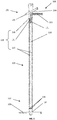
- Figure 1 shows a schematic cross section of an intramedullary nail 100.
- the intramedullary nail 100 has an axially extending first conduit means 110.
- the first conduit means 110 extends axially from a first end 101 to a second end 102 of the intramedullary nail 100 first reservoir for a pharmaceutical fluid can be connected in a fluid-conducting manner.
- the first conduit means 110 is partially designed as an axially running channel within the intramedullary nail 100, through which a pharmaceutical fluid, in particular a liquid pharmaceutical fluid, can be conveyed.
- the intramedullary nail 100 has passages 130 which connect the first line means 110 to a second line means 120 and via the second line means 120 also to an outer surface 105 of the intramedullary nail 100 in a fluid-conducting manner.
- the intramedullary nail 100 shown has four passages (one passage 130 pointing out of the plane of the drawing and a further passage 130 directed behind the plane of the drawing and thus not visible), each of which is radially offset from one another at an angle of 90 ° on the intramedullary nail 100 are arranged.
- embodiments of intramedullary nail 100 both the number and the arrangement of the feedthroughs 130 can vary.
- the second conduit means 120 comprises four grooves 125 running axially in the outer surface 105 (again, analogous to the feedthroughs 130, one of the axial grooves 125 running in front of the plane of the drawing and another groove 125 running behind the plane of the drawing), which extends connect directly to the four passages 130, a radially circumferential depression 126 and a channel-like second connection 121 at the first end 101 of the intramedullary nail 100, the channel-like depression 126 connecting the second connection 121 and the grooves 125 in a fluid-conducting manner.
- the first connector 111 and the second connector 121 are designed in one piece, in such a way that a first reservoir and a second reservoir can be connected to the intramedullary nail 100 with a double hose system.
- the first connection 111 and the second connection 121 can be configured separately from one another, so that a first reservoir and a second reservoir each have a separate connection means, such as a hose, to the first connection 111 and the second Connection 121 can be connected.
- the first end 101 is on by means of a screw connection 107 Rest of intramedullary nail 100 attached.
- the first end 101 and the rest of the intramedullary nail 100 are configured in one piece.
- the intramedullary nail 100 allows a pharmaceutical fluid to be conveyed in two directions of flow.
- the pharmaceutical fluid can be introduced into the intramedullary nail 100 via the first connection 111 into the first conduit means 110 and conveyed in the direction of the second end 102 through the first conduit means 110, and when it reaches the second end 102 it exits through the feedthroughs 130 the intramedullary nail 100 is guided into the grooves 125.
- the grooves 125 guide the pharmaceutical fluid back again in the direction of the first end 101, where it is collected by the radially encircling depression 126 and passed into a second reservoir by means of the second connection 121.
- the pharmaceutical fluid can be introduced from a second reservoir via the second connection 121 into the second conduit means 120 in the intramedullary nail 100 and conveyed in the direction of the second end 102, it being first through the radially circumferential recess 126 and then via the Grooves 125 is guided.
- the pharmaceutical fluid is introduced from the grooves 125 through the feedthroughs 130 into the first conduit 110.
- the first conduit means 110 conducts the pharmaceutical fluid back again in the direction of the first end 101, whereby it is transferred from the intramedullary nail 100 into a first reservoir by means of the first connection 111 when the first end 101 is reached.
- the pharmaceutical fluid is in fluid-conducting connection via the grooves 125 with the outer surface 105 of the intramedullary nail 100, which allows the active ingredient contained in the pharmaceutical fluid to be applied to the surrounding bone tissue of the implanted intramedullary nail 100.
- Bores 104 each provided with a fastening means 103 in the form of a screw, are provided at the first end 101 and at the second end 102.
- the fastening means 103 serve to spatially fix the intramedullary nail 100 within a bone canal.
- FIG. 11 shows a schematic external view of the intramedullary nail 100 from FIG Figure 1 .
- one of the passages 130 from the interior of the intramedullary nail 100 opens into one of the grooves 125.
- the corresponding groove 125 runs axially from the second end 102 to the first end 101 in the outer surface 105 of the intramedullary nail 100, where it conducts fluid is connected to the radially circumferential recess 126.
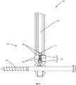
- FIG. 11 shows a detail of a schematic cross section of the intramedullary nail 100 from FIG Figures 1 and 2 , wherein the first conduit means 110 additionally has a first restoring element 140.
- the first check valve is located at an end 112 of the first conduit means 110 facing the second end 102 of the intramedullary nail 100, directly at the transition to the feedthroughs 130 and is in a closed position.
- a first restoring element 141 in the form of a spring biases a first piston 142 in such a way that it closes the transition from the first conduit means 110 and the feedthroughs 130 in a fluid-conducting manner.
- the intramedullary nail 100 has a second sealing ring 155 at the second end 102, which surrounds the intramedullary nail 100 radially.
- the second sealing ring 155 interacts with the bone tissue surrounding the intramedullary nail 100 in such a way that a pharmaceutical fluid conveyed through the intramedullary nail 100 and exiting the ducts 130 in the direction of the first end 101 and not in the direction of the fastening means 103 of the second end 102 is passed. This prevents uncontrolled accumulation of the active substance contained in the pharmaceutical fluid in the patient's body.
- the intramedullary nail 100 has the second sealing ring 155, but not the first check valve 110.
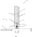
- FIG. 11 shows a detail of a schematic cross section of the intramedullary nail 100 from FIG Figures 1 , 2 and 3 , the additional first check valve 140 from Figure 3 shown in an open position.
- Figure 4 shows a conveyance of a pharmaceutical fluid through the first conduit means 110 in the direction of the feedthroughs 130 and along the grooves 125 back again to the first end 101 of the intramedullary nail 100, as illustrated with the aid of the arrows 106.
- the first check valve 140 Triggered by a delivery pressure of the pharmaceutical fluid through the first conduit means 110 in the direction of the second end 102, the first check valve 140 is in the open position because the pharmaceutical fluid moves the first piston 142 of the first check valve 140 against the clamping force of the first return element 141 in The direction of the bore 104 at the second end 102 shifts.
- the first check valve thus allows a pharmaceutical fluid to be conveyed only along the lines illustrated by the arrows 106 Direction of flow, as a result of which the risk of contamination and / or clogging of the first conduit means 110 is reduced.
- Figure 5 shows a detail of a schematic cross section of the intramedullary nail 100 from the previous figures, the second conduit means 120, in particular the second connection 121, additionally having a second check valve 145.
- Figure 5 shows the second check valve 145 in a closed position.
- a second restoring element 146 in the form of a spring biases a second piston 147 such that it closes the second conduit means 120, in particular the second connection 121, in a fluid-conducting manner in the flow direction of the radial recess.
- the closed position of the second check valve 145 it is not possible to convey a pharmaceutical fluid through the second connection 121 in the direction of the second end 102 of the intramedullary nail 100.
- intramedullary nail 100 has only second check valve 145.
- the intramedullary nail 100 has the first check valve 140 according to FIG Figures 3 and 4th and the second check valve 145.
- the second check valve 145 is arranged in the channel-like second connection 121, in particular at an end of the second connection 121 facing the radial recess 126.
- the intramedullary nail 100 has a first sealing ring 150 at the first end 101, which surrounds the intramedullary nail 100 radially.
- the first sealing ring 150 interacts with the bone tissue surrounding the intramedullary nail 100 such that a pharmaceutical fluid conveyed through the intramedullary nail 100, which is conveyed through the grooves 125 in the direction of the first end 101, into the second connection 121 and is not diverted in the direction of the fastening means 103 at the first end 101. This prevents uncontrolled accumulation of the active substance contained in the pharmaceutical fluid in the patient's body.
- the intramedullary nail 100 has the second sealing ring 155, but not the first check valve 110.
- the intramedullary nail has both the first sealing ring 150 and the second sealing ring 155. This enables a controlled delivery of a pharmaceutical fluid from one reservoir to another reservoir, preferably from the first reservoir to the second reservoir, without the active ingredient contained in the pharmaceutical fluid being accumulated in an undesired manner.
- Figure 6 shows the detail of a schematic cross section of the intramedullary nail 100 from the previous figures, the additional second check valve 145 from Figure 5 shown in an open position.
- Figure 6 shows a conveyance of a pharmaceutical fluid through the first line means 110 in the direction of the second end 102 and through the second line means 120 back again in the direction of the first end 101 of the intramedullary nail, as illustrated with the aid of the arrows 106.
- the second check valve 145 is in the open position, in that the pharmaceutical fluid pushes the second piston 147 of the second check valve 145 against the clamping force of the second return element 141 in The direction of the bore 104 at the first end 101 shifts.
- the second check valve thus allows a pharmaceutical fluid to be conveyed only in the flow direction illustrated along the arrows 106, as a result of which the risk of contamination and / or blockage, in particular of the first conduit means 110, is reduced.
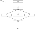
- Figure 7 shows a flow diagram of a method 200 for the treatment of bone fractures and for the application of a pharmaceutical fluid in the area of the bone canal by means of an intramedullary nail, comprising steps 210, 220, 230 and / or 240 as well as an optional step 250.
- the intramedullary nail is in implanted the bone canal and, in step 220, a first line of the intramedullary nail with a first reservoir for pharmaceutical fluids and a second line of the intramedullary nail with a second reservoir for pharmaceutical fluids connected in a fluid-conducting manner, for example via one or more tubes.
- the method 200 can be carried out in three different ways.
- a pharmaceutical fluid is at least partially conveyed from the first reservoir into the second reservoir, for example by pumping. The pharmaceutical fluid is not conveyed from the second reservoir into the first reservoir.
- a pharmaceutical fluid is at least partially conveyed from the second reservoir into the first reservoir, for example by pumping. The pharmaceutical fluid is not conveyed from the first reservoir into the second reservoir.
- both an at least partial delivery of a pharmaceutical fluid from the first reservoir into the second reservoir and an at least partial delivery from the second reservoir into the first reservoir are carried out.
- the first reservoir and the second reservoir can each store the same pharmaceutical fluid or a different pharmaceutical fluid before the first delivery, or only the first reservoir or only the second Reservoirs store a pharmaceutical fluid before the first delivery.
- the first reservoir is separated from the first conduit means and the second reservoir is separated from the second conduit means in a fluid-conducting manner.
Landscapes
- Health & Medical Sciences (AREA)
- Orthopedic Medicine & Surgery (AREA)
- Surgery (AREA)
- Life Sciences & Earth Sciences (AREA)
- Molecular Biology (AREA)
- Animal Behavior & Ethology (AREA)
- Engineering & Computer Science (AREA)
- Biomedical Technology (AREA)
- Heart & Thoracic Surgery (AREA)
- Medical Informatics (AREA)
- Veterinary Medicine (AREA)
- Nuclear Medicine, Radiotherapy & Molecular Imaging (AREA)
- General Health & Medical Sciences (AREA)
- Public Health (AREA)
- Neurology (AREA)
- Pathology (AREA)
- Gastroenterology & Hepatology (AREA)
- Surgical Instruments (AREA)
- Prostheses (AREA)
- Infusion, Injection, And Reservoir Apparatuses (AREA)
Abstract
Description
- Die Erfindung betrifft einen Marknagel zur Applikation eines pharmazeutischen Fluids, umfassend ein axial im Marknagel verlaufendes fluidleitendes erstes Leitungsmittel, welches mit einem ersten Reservoir für das pharmazeutische Fluid verbindbar ist und mindestens eine Durchführung, welche das erste Leitungsmittel fluidleitend mit einer Außenfläche des Marknagels verbindet.
Die Erfindung betrifft weiterhin ein Verfahren Behandlung von Knochenfrakturen und zur Applikation eines pharmazeutischen Fluids in den Bereich eines Knochenkanals mittels eines Marknagels. - Zur chirurgischen Versorgung von offenen, als auch von geschlossenen, Knochenfrakturen, insbesondere zur Behandlung bei Knochenfrakturen von großen Röhrenknochen, hat sich seit Jahrzehnten der Einsatz von Marknägeln bewährt. Dazu wird zur Reposition und Stabilisierung des frakturierten Knochens ein Marknagel in den Knochenkanal eingeführt und fixiert, welcher zumindest bis zur Heilung der Knochenfraktur innerhalb des Knochenkanals verbleibt.
- Durch Knochenfrakturen, Insbesondere durch offene Knochenfrakturen, kann es zu Kontaminationen des Knochengewebes mit Mikroorganismen kommen. Die so ausgelösten Infektionen, wie beispielsweise eine Osteitis, insbesondere eine Osteomyelitis, stellen sehr schwerwiegende Erkrankungen dar.
Zur Behandlung der mikrobiellen Infektionen ist nach einem chirurgischen Debridement des infizierten Knochengewebes eine lokale Gabe von Antibiotika üblich. - In der
US 8,609,003 B2 und derUS 5,618,286 A werden Marknägel beschrieben, welche mit PMMA-Knochenzement umhüllt sind, der ein oder mehrere Antibiotika enthält. Nachteilig gestaltet sich dabei, dass die im PMMA-Knochenzement inkorporierten Antibiotika nur innerhalb der ersten Tage nach der Implantation des Marknagels eine ausreichend hohe Konzentration an Antibiotika freisetzen können, was für eine abschließende Bekämpfung der Infektion zu kurz sein kann. Weiterhin kann die Antibiotikazusammensetzung nach erfolgter Implantation nicht variiert werden, was insbesondere im Falle einer Unwirksamkeit der im PMMA-Knochenzement enthaltenen Antibiotika nachteilig ist. - Eine Weiterentwicklung stellen daher Marknägel mit perforiertem Marknagelkörper dar, mittels derer nach erfolgter Implantation über ein Leitungsmittel verschiedene pharmazeutische Fluide, wie beispielsweise antiseptische Wirkstofflösungen, lokal am infizierten Knochengewebe über Zuleitung von außen appliziert werden kann. Solche Marknägel werden beispielsweise in der
US 5,681,289 A , derCN 2857862 Y und derCN 201370624 Y beschrieben. Dabei kann eine antiseptische Wirkstofflösung durch Durchführungen in den entsprechenden Marknägeln austreten und das infizierte Knochengewebe erreichen. - Ein Nachteil der beschriebenen Marknägel besteht in einer ungewollten Anreicherung des im pharmazeutischen Fluids enthaltenen Wirkstoffs im Patientenkörper, welche durch den beim Einpressen des Fluids in den Knochenkanal benötigten, hohen Applikationsdruck verursacht wird. Bei einer Reihe von Antibiotika, wie beispielsweise Aminoglykosid-Antibiotika, können hohe systemische Antibiotika-Konzentrationen Schädigungen des Patienten, wie beispielsweise Nierenschäden und Schäden am Hörnerv, verursachen. Weiterhin wird durch den durch die Applikation hervorgerufenen Druckaufbau das Risiko von Embolien erhöht. Zudem kann zu einem unkontrolliertem Rückfließen des pharmazeutischen Fluids durch den zuvor zur Einleitung genutzten Zugang, und damit zur Kontamination des Spülsystems, insbesondere des Marknagels, kommen.
- Eine Aufgabe der vorliegenden Erfindung ist es, einen oder mehrere der sich aus dem Stand der Technik ergebenen Nachteile zumindest teilweise zu überwinden.
- Im Speziellen basiert die Erfindung auf dem Ziel, Marknägel bereitzustellen, welche in der Lage sind den Innenraum von Knochen, insbesondere von Röhrenknochen, mit pharmazeutischen Fluiden beliebiger Zusammensetzung, insbesondere mit antiseptischen Wirkstofflösungen, wie beispielsweise antibiotikahaltigen Wirkstofflösungen, zu spülen. Dabei soll das pharmazeutische Fluid von einem außerhalb des Patientenkörpers angeordneten Reservoir dem Marknagel zuführbar sein und gleichzeitig Nebenwirkungen, wie beispielsweise die Anreicherung des zugeführten Wirkstoffs im Patientenkörper und die Ausbildung von Embolien, insbesondere von Fettembolien, vermieden werden. Das Ziel ist zudem, die Wirkstofflösung zuverlässig über den Innenraum der Knochen zu verteilen und gleichzeitig eine hohe mechanische Stabilität der Marknägel und eine sichere Fixierung derselben im Knochen zu gewährleisten. Zudem sollen die Marknägel ein sicheres und kontrollierbares Spülen eines Innenraums eines Knochens ermöglichen, ohne dass es dabei zu einer Kontamination oder einer Verstopfung der Marknägel, insbesondere durch Eindringen von Knochengewebe in die Marknägel, kommt.
- Ein Beitrag zur mindestens teilweisen Erfüllung mindestens einer der zuvor genannten Aufgaben wird durch die Merkmale der unabhängigen Ansprüche geleistet. Die abhängigen Ansprüche stellen bevorzugte Ausführungsformen bereit, die zur mindestens teilweisen Erfüllung mindestens einer der Aufgaben beitragen.
- |1| Marknagel zur Applikation eines pharmazeutischen Fluids, umfassend
ein axial im Marknagel verlaufendes fluidleitendes erstes Leitungsmittel, welches mit einem ersten Reservoir für das pharmazeutische Fluid verbindbar ist und
mindestens eine Durchführung, welche das erste Leitungsmittel fluidleitend mit einer Außenfläche des Marknagels verbindet,
dadurch gekennzeichnet, dass
ein fluidleitendes zweites Leitungsmittel die Außenfläche derart mit einem zweiten Reservoir verbindet, um das pharmazeutische Fluid zwischen dem ersten Reservoir und dem zweiten Reservoir zu fördern. - |2| Marknagel nach Ausführungsform 1, dadurch gekennzeichnet, dass das erste Leitungsmittel einen ersten Anschluss zur fluidleitenden Verbindung mit dem ersten Reservoir und das zweite Leitungsmittel einen zweiten Anschluss zur fluidleitenden Verbindung mit dem zweiten Reservoir umfasst, wobei der erste Anschluss und der zweite Anschluss an einem ersten Ende des Marknagels angeordnet sind.
- |3| Marknagel nach Ausführungsform 2, dadurch gekennzeichnet, dass die mindestens eine Durchführung an einem dem ersten Ende entgegengesetzten zweitem Ende des Marknagels angeordnet ist.
- |4| Marknagel nach einer der vorhergehenden Ausführungsformen, dadurch gekennzeichnet, dass das zweite Leitungsmittel zumindest partiell als mindestens eine sich axial erstreckende Nut in der Außenfläche ausgebildet ist.
- |5| Marknagel nach Ausführungsform 4, dadurch gekennzeichnet, dass die mindestens eine sich axial erstreckende Nut fluidleitend mit der mindestens einen Durchführung verbunden ist.
- |6| Marknagel nach Ausführungsform 4 oder 5, dadurch gekennzeichnet, dass das zweite Leitungsmittels als zwei bis sechs, insbesondere als vier, sich axial erstreckende Nuten in der Außenfläche ausgebildet ist und der Marknagel die gleiche Anzahl an Durchführungen aufweist, wobei jeweils eine Nut mit jeweils einer Durchführungen fluidleitend miteinander verbunden ist.
- |7| Marknagel nach einer der vorhergehenden Ausführungsformen, dadurch gekennzeichnet, dass das erste Leitungsmittel ein erstes Rückschlagventil aufweist.
- |8| Marknagel nach Ausführungsform 7, dadurch gekennzeichnet, dass das erste Rückschlagventil in Richtung der mindestens einen Durchführung fluiddurchlässig ausgestaltet ist.
- |9| Marknagel nach Ausführungsform 7 oder 8, dadurch gekennzeichnet, dass das erste Rückschlagventil ein erstes Rückstellelement, insbesondere eine erste Feder, aufweist.
- |10| Marknagel nach einer der vorhergehenden Ausführungsformen, dadurch gekennzeichnet, dass das zweite Leitungsmittel ein zweites Rückschlagventil aufweist.
- |11| Marknagel nach Ausführungsform 10, dadurch gekennzeichnet, dass das zweite Rückschlagventil in Richtung der Außenfläche fluidundurchlässig ausgestaltet ist.
- |12| Marknagel nach Ausführungsform 10 oder 11, dadurch gekennzeichnet, dass das zweite Rückschlagventil ein zweites Rückstellelement, insbesondere eine zweite Feder, aufweist.
- |13| Marknagel nach einer der vorhergehenden Ausführungsformen, dadurch gekennzeichnet, dass der Marknagel mindestens eine Bohrung aufweist, um den Marknagel innerhalb eines Knochenkanals zu fixieren.
- |14| Verfahren zur Behandlung von Knochenfrakturen und zur Applikation eines pharmazeutischen Fluids in den Bereich des Knochenkanals mittels eines Marknagels umfassend
ein axial im Marknagel verlaufendes fluidleitendes erstes Leitungsmittel, welches mit einem ersten Reservoir für das pharmazeutische Fluid verbindbar ist,
mindestens eine Durchführung, welche das erste Leitungsmittel fluidleitend mit einer Außenfläche des Marknagels verbindet, wobei die Außenfläche über ein fluidleitendes zweites Leitungsmittel mit einem zweiten Reservoir für das pharmazeutische Fluid verbindbar ist,
zumindest umfassend die Schritte- a) Implantieren des Marknagels in den Knochenkanal;
- b) Fluidleitendes Verbinden des ersten Leitungsmittels mit dem ersten Reservoir und des zweiten Leitungsmittels mit dem zweiten Reservoir;
- c1) zumindest partielles Fördern des pharmazeutischen Fluids aus dem ersten Reservoir über das erste Leitungsmittel, die mindestens eine Durchführung, die Außenfläche und das zweite Leitungsmittel in das zweite Reservoir; und/oder
- c2) zumindest partielles Fördern des pharmazeutischen Fluids aus dem zweiten Reservoir über das zweite Leitungsmittel, die Außenfläche, die mindestens eine Durchführung und das erste Leitungsmittel in das erste Reservoir.
- |15| Verfahren nach Ausführungsform 14, dadurch gekennzeichnet, dass das Verfahren die Schritte a), b) und c1) umfasst.
- In der vorliegenden Beschreibung beinhalten Bereichsangaben auch die als Grenzen genannten Werte. Eine Angabe der Art "im Bereich von X bis Y" in Bezug auf eine Größe A bedeutet folglich, dass A die Werte X, Y und Werte zwischen X und Y annehmen kann. Einseitig begrenzte Bereiche der Art "bis zu Y" für eine Größe A bedeuten entsprechend als Wert Y und kleiner als Y.
- Einige der beschriebenen Merkmale sind mit dem Begriff "im Wesentlichen" verknüpft. Der Begriff "im Wesentlichen" ist so zu verstehen, dass unter realen Bedingungen und Fertigungstechniken eine mathematisch exakte Auslegung von Begrifflichkeiten wie "Überlagerung", "senkrecht", "Durchmesser" oder "Parallelität" nie exakt, sondern nur innerhalb gewisser fertigungstechnischer Fehlertoleranzen gegeben sein kann. Beispielsweise schließen "im Wesentlichen parallele Achsen" einen Winkel von 85 Grad bis 95 Grad zueinander ein und "im Wesentlichen gleiche Volumen" umfassen eine Abweichung von bis zu 5 Volumen-%. Eine "im Wesentlichen aus Kunststoff bestehende Vorrichtung" umfasst beispielsweise einen Kunststoffanteil von ≥95 bis ≤100 Gewichts-%. Eine "im Wesentlichen vollständige Befüllung eines Volumens B" umfasst beispielsweise eine Befüllung von ≥95 bis ≤100 Volumen-% des Gesamtvolumens von B.
- Ein erster Gegenstand der Erfindung betrifft einen Marknagel zur Applikation eines pharmazeutischen Fluids, umfassend
ein axial im Marknagel verlaufendes fluidleitendes erstes Leitungsmittel, welches mit einem ersten Reservoir für das pharmazeutische Fluid verbindbar ist und
mindestens eine Durchführung, welche das erste Leitungsmittel fluidleitend mit einer Außenfläche des Marknagels verbindet,
dadurch gekennzeichnet, dass
ein fluidleitendes zweites Leitungsmittel die Außenfläche derart mit einem zweiten Reservoir verbindet, um das pharmazeutische Fluid zwischen dem ersten Reservoir und dem zweiten Reservoir zu fördern. - Ein Marknagel stellt eine intramedulläre Schienung bei der Behandlung einer Knochenfraktur insbesondere eines Röhrenknochens dar, welche den Knochen bis zur Heilung der Knochenfraktur stabilisiert. In der Praxis kommen überwiegend aufgebohrte und nicht-aufgebohrte Marknägel zum Einsatz, wobei sich die Begrifflichkeiten "aufgebohrt" und "nichtaufgebohrt" auf die Implantationsmethode der Marknägel bezieht. Bei aufgebohrten Marknägeln wird der gesamte Markraum des Röhrenknochens aufgebohrt und anschließend der Marknagel in den aufgebohrten Knochenkanal eingeschlagen. Eine mechanische Verriegelung zur Fixierung des Marknagels innerhalb des Knochenkanals ist nicht obligat.
Nicht-aufgebohrte Marknägel sind massiver, aber dünner als aufgebohrte Marknägel, wobei eine Fixierung mit Verriegelungsschrauben in der Regel geboten ist. Die erfindungsgemäße Marknagel kann sowohl als aufgebohrter Marknagel, als auch als nicht-aufgebohrter Marknagel verwendet werden, wobei die Verwendung als aufgebohrter Marknagel bevorzugt ist. - Der erfindungsgemäße Marknagel dient zur Applikation eines pharmazeutischen Fluids zur Behandlung infizierten Knochengewebes, insbesondere zur Applikation innerhalb des Knochenkanals des Knochens, über einen Zeitraum von mehreren Tagen bis Wochen. Ein pharmazeutisches Fluid enthält wenigstens einen pharmazeutischen Wirkstoff. Beispielsweise handelt es sich bei dem pharmazeutischen Fluid um wässrige oder nicht-wässrige Lösungen oder Suspensionen von pharmazeutischen Wirkstoffen.
In einer Ausgestaltungsform handelts es sich bei dem pharmazeutisches Fluid um Lösungen, welche wenigstens ein Antibiotikum, wenigstens ein Chemotherapeutikum und/oder wenigstens ein Antimykotikum enthalten. In einer weiteren Ausgestaltungsform enthalten die pharmazeutischen Fluide wenigstens einen desinfizierenden Bestandteil.
Weiterhin umfassen pharmazeutische Fluide auch Gase, Gasgemische und Lösungen von Gasen in Flüssigkeiten, wie beispielsweise Wasser. - Der Marknagel weist ein erstes Leitungsmittel und ein zweites Leitungsmittel auf. Unter einem Leitungsmittel werden alle Elemente verstanden, welche zwei Strukturen fluidleitend miteinander verbinden können. Beispiele für solche Elemente sind rohrartige, schlauchartige oder kanalartige Verbindungen.
- Um eine für die Applikation des pharmazeutischen Fluids ausreichend hohe Durchflussrate zu gewährleisten, kann das erste Leitungsmittel und/oder das zweite Leitungsmittel beispielsweise einen Innenquerschnitt von 0,5 mm2 bis 5 mm2, bevorzugt von 1 mm2 bis 4 mm2 aufweisen. Um ein Fördern von Feststoffen, und damit ein Risiko einer Verstopfung des ersten Leitungsmittels und/oder des zweiten Leitungsmittel zu verhindern kann das erste Leitungsmittel und/oder das zweite Leitungsmittel jeweils ein Sieb aufweisen oder aus einem Sieb bestehen.
- Das erste Leitungsmittel verläuft zumindest partiell axial innerhalb des Marknagels. Der axiale Verlauf des ersten Leitungsmittel innerhalb des Marknagels kann auf unterschiedliche Weisen ausgestaltet sein. Aufgrund der leichten Fertigungsweise verläuft das erste Leitungsmittel bevorzugt zumindest partiell parallel zur Längsachse des Marknagels.
- Die Wegstrecke, die das erste Leitungsmittel innerhalb des Marknagels axial verläuft, kann unterschiedliche lang ausgestaltet sein. Beispielsweise kann das erste Leitungsmittel durch 1-100% einer Gesamtlänge des Marknagels axial verlaufen. Das erste Leitungsmittel kann beispielsweise mindestens 1 %, 10 %, 70 %, 80 % der Gesamtlänge des Marknagels axial durchlaufen. Als Obergrenze kann das erste Leitungsmittel maximal 100 %, 95 %, 90 % oder 85 % der Gesamtlänge des Marknagels axial durchlaufen.
- Der Marknagel ist über das erste Leitungsmittel mit einem ersten Reservoir und über das zweite Leitungsmittel mit einem zweiten Reservoir für ein pharmazeutisches Fluid fluidleitend verbindbar. Unter einem Reservoir werden alle Behältnisse verstanden, welche dazu geeignet sind, das pharmazeutische Fluid bereitzustellen und/oder aufzunehmen. Beispiele für Reservoire umfassen Beutel, Spritzen, Kolben, Ballons, Kanister und Ampullen, wobei Beutel, Ballons und Spritzen bevorzugt sind. Als ein Reservoir zur Aufnahme des pharmazeutischen Fluids kann es sich zudem darüber hinaus um einen Beutel, ein Gefäß oder einen andersartigen Auffangbehälter handeln, welcher nicht strukturell mit dem ersten Leitungsmittel oder dem zweiten Leitungsmittel verbunden sein muss, aber dazu geeignet ist, das aus dem ersten Leitungsmittel oder dem zweiten Leitungsmittel austretende pharmazeutische Fluid aufzufangen. In einer Ausgestaltungsform kann das das pharmazeutische Fluid aufnehmende Reservoir auch ein Raum oder ein Boden eines Raums sein, in den das aus dem ersten Leitungsmittel oder dem zweiten Leitungsmittel austretende pharmazeutische Fluid ausgeleitet wird oder auf den das, in diesem Fall flüssige pharmazeutische Fluid, fließt oder tropft.
- Das erste Leitungsmittel ist über mindestens eine Durchführung mit einer Außenfläche des Marknagels fluidleitend verbunden, wobei die Außenfläche die Fläche des Marknagels darstellt, welche in physischem Kontakt mit dem Knochengewebe des Patienten steht. In einer Ausgestaltungsform ist die mindestens eine Durchführung als mindestens eine Perforation im Marknagel ausgestaltet, welche das erste Leitungsmittel mit der Außenfläche fluidleitend verbindet. Um eine für die Applikation des pharmazeutischen Fluids ausreichend hohe Durchflussrate durch die mindestens eine Durchführung zu gewährleisten, kann die Durchführung einen Innenquerschnitt von 0,5 mm2 bis 5 mm2, bevorzugt von 1 mm2 bis 4 mm2 von aufweisen. Um ein Fördern von Feststoffen, und damit ein Risiko einer Verstopfung der Durchführung zu verhindern, kann die mindestens eine Durchführung ein Sieb aufweisen, aus einem Sieb bestehen oder einen Verschluss, wie beispielsweise eine Klappe, aufweisen, welcher sich erst beim Fördern des pharmazeutischen Fluids durch die mindestens eine Durchführung öffnet, ansonsten aber verschlossen bleibt und somit ein Einwachsen von Gewebe, und damit einem Verstopfen der mindestens einen Durchführung, verhindert.
- Das erste Reservoir ist über das erste Leitungsmittel, die mindestens eine Durchführung, die Außenfläche des Marknagels und das zweite Leitungsmittel fluidleitend mit dem zweiten Reservoir verbindbar, um das pharmazeutische Fluid zwischen dem ersten Reservoir und dem zweiten Reservoir zu fördern, so dass das pharmazeutische Fluid an das den Marknagel umgebende infizierte Knochengewebe applizierbar ist.
- In einer Ausgestaltungsform ist das pharmazeutische Fluid aus dem ersten Reservoir über das erste Leitungsmittel, die mindestens eine Durchführung, die Außenfläche des Marknagels und das zweite Leitungsmittel in das zweite Reservoir förderbar. In einer weiteren Ausgestaltungsform ist das pharmazeutische Fluid aus dem zweiten Reservoir über das zweite Leitungsmittel, die Außenfläche des Marknagels, die mindestens eine Durchführung und das erste Leitungsmittel in das erste Reservoir förderbar.
- In beiden Ausgestaltungsformen kommt das pharmazeutischen Fluid über die Außenfläche des Marknagels mit dem Knochengewebe des Patienten in Kontakt und erlaubt somit eine Applikation des in dem pharmazeutischen Fluids enthaltenen Wirkstoff zur Bekämpfung von Infektionen im Bereich der Knochenfraktur. Gleichzeitig verbleibt das pharmazeutische Fluid nicht im Bereich des infizierten Knochengewebes, sondern kann in das erste Reservoir oder das zweite Reservoir abgeführt werden. Somit erzeugt ein fortgeführtes Zuführen des pharmazeutischen Fluids keinen Druckaufbau durch im Knochenkanal verbleibendes Fluid, wodurch ein unerwünschtes erhöhtes Einbringen des Wirkstoffs in den Blutkreislauf des Patienten unterbunden wird. Dies verhindert ein Anreichern des Wirkstoffs im Patienten und verringert zudem das Risiko von Embolien.
- Eine Ausgestaltungsform des Marknagels ist dadurch gekennzeichnet, dass das erste Leitungsmittel einen ersten Anschluss zur fluidleitenden Verbindung mit dem ersten Reservoir und das zweite Leitungsmittel einen zweiten Anschluss zur fluidleitenden Verbindung mit dem zweiten Reservoir umfasst, wobei der erste Anschluss und der zweite Anschluss an einem ersten Ende des Marknagels angeordnet sind.
- Unter einem Anschluss ist eine Struktureinheit zu verstehen, welche ein fluidleitendes Verbinden von Leitungsmittel und Reservoir erlaubt. In einer Ausgestaltungsform ist der Anschluss als Tülle ausgeformt, über die das Leitungsmittel mittels Schlauchs mit dem Reservoir fluidleitend verbindbar ist. In einer weiteren Ausgestaltungsform ist der Anschluss als Gewinde ausgeformt, welches über ein entsprechendes Gegenstück fluidleitend mit dem Reservoir verbindbar ist. In einer weiteren Ausgestaltungsform formt der Anschluss mit dem Reservoir eine Flanschverbindung. In einer weiteren Ausgestaltungsform formt der Anschluss über eine Schlauchkupplung mit dem Reservoir eine fluidleitende Verbindung, wobei der Anschluss die Kupplung oder den Nippel der Schlauchkupplung aufweisen kann.
- Der erste Anschluss und der zweite Anschluss sind gemeinsam an einem ersten Ende des Marknagels angeordnet, so dass das Zu- und Abführen des pharmazeutischen Fluids in beziehungsweise aus dem Knochenkanal am gleichen Ende des Knochens vonstattengehen kann. Vorzugsweise befindet sich der erste Anschluss und der zweite Anschluss an dem Ende des Marknagels, welches der für die Implantation des Marknagels vorgesehenen Öffnung des Knochens zugewandt ist. In einer bevorzugten Ausgestaltungsform bilden der erste Anschluss und der zweite Anschluss ein gemeinsames Strukturelement, wie beispielsweise eine gemeinsame Tülle, aus, welches die Verwendung eines Doppelschlauchsystems zum Zu- und Abführen des pharmazeutischen Fluids in beziehungsweise aus dem Marknagel erlaubt.
- Eine Ausgestaltungsform des Marknagels ist dadurch gekennzeichnet, dass die mindestens eine Durchführung an einem dem ersten Ende entgegengesetzten zweitem Ende des Marknagels angeordnet ist. Somit erstreckt sich das erste Leitungsmittel vom ersten Ende des Marknagels, wo sich der erste Anschluss befindet, bis zum zweiten Ende des Marknagels, an dem die Durchführung das erste Leitungsmittel mit der Außenfläche des Marknagels fluidleitend verbindet. Vorzugsweise erstreckt sich das erste Leitungsmittel axial über 70-100 %, weiter bevorzugt über 80-100 %, noch weiter bevorzugt über 85-95 % der Gesamtlänge des Marknagels.
- In einer bevorzugten Ausgestaltungsform ist das zweite Leitungsmittel derart ausgestaltet, beispielsweise als zumindest ein Kanal in den Marknagels hinein, dass ein Ableiten des pharmazeutischen Fluids von der Außenfläche des Marknagels am ersten Ende des Marknagels erfolgt. Bevorzugt wird das pharmazeutische Fluid zumindest über 60-100 %, bevorzugt 70-100 %, weiter bevorzugt zwischen 80-95 % der Gesamtlänge des Marknagel entlang der Außenfläche, beginnend mit der zumindest einen Durchführung, geleitet, bevor es mittels der ableitenden Ausgestaltung des zweiten Leitungsmittels von der Außenfläche gefördert wird. Dies sorgt dafür, dass das pharmazeutische Fluid einen Großteil der Gesamtlänge des Marknagel an der Außenfläche entlanggeführt wird, während ein Fördern zwischen dem ersten Reservoir und dem zweiten Reservoir durchgeführt wird. Damit erlaubt der Marknagel eine großflächige Behandlung infizierten Knochengewebes.
- Das pharmazeutische Fluid kann auf unterschiedliche Weisen entlang der Außenfläche des Marknagels geführt werden.
- Eine Ausgestaltungsform des Marknagel ist dadurch gekennzeichnet, dass das zweite Leitungsmittel zumindest partiell als mindestens eine sich axial erstreckende Nut in der Außenfläche ausgebildet ist. Durch die mindestens eine Nut kann das pharmazeutische Fluid sicher, in größeren Mengen und ohne das Risikos einer Verstopfung gefördert werden, wobei eine Benetzung der Außenfläche entlang der Nut eine wirksame Bekämpfung einer Infektion sicherstellt. Somit kommt es nicht zu einem Druckaufbau durch fortgeführtes Fördern des pharmazeutischen Fluids zwischen dem ersten Reservoir und dem zweiten Reservoir, was ein ungewolltes Anreichern des im pharmazeutischen Fluids enthaltenen Wirkstoffs unterbindet und das Risiko von Embolien vermindert. Bevorzugt ist das zweite Leitungsmittel als mehrere, beispielsweise als zwei bis zehn, axial verlaufende Nuten ausgebildet, welche radial über die Außenfläche des Marknagels verteilt sind.
- Dies erlaubt eine großflächige Applikation des pharmazeutischen Fluids im gesamten Bereich des Marknagels bei gleichzeitig vermindertem Risiko eines ungewollten Druckaufbaus beim Fördern.
- Die zumindest eine sich axial erstreckende Nut kann unterschiedlich ausgestaltet sein. In einer Ausgestaltungsform verläuft die zumindest eine sich axial erstreckende Nut in wellenförmigen Auslenkungen entlang der Außenfläche. In einer weiteren Ausgestaltungsform verläuft die mindestens eine Nut schraubenförmig entlang der Außenfläche. Aufgrund der leichteren Fertigung verläuft die zumindest eine sich axial erstreckende Nut im Wesentlichen parallel zur Längsachse des Marknagels.
- Die zumindest eine Nut kann sich unterschiedlich lang entlang der Längsachse des Marknagels erstrecken. Beispielsweise kann sich die zumindest eine Nut über 5-100 %, bevorzugt über 50-100 %, weiter bevorzugt über 70-95 % der Gesamtlänge des Marknagels entlang der Außenfläche erstrecken.
- Die mindestens eine Durchführung und das zweite Leitungsmittel können auf unterschiedliche Weise fluidleitend miteinander verbunden sein. In einer Ausgestaltungsform sind die mindestens eine Durchführung und das zweite Leitungsmittel, insbesondere in Form zumindest einer sich axial in der Außenfläche erstreckende Nut, nicht direkt, sondern nur über die Außenfläche des Marknagel miteinander fluidleitend verbunden.
- Eine Ausgestaltungsform des Marknagels ist dadurch gekennzeichnet, dass die mindestens eine sich axial erstreckende Nut direkt fluidleitend mit der mindestens eine Durchführung verbunden ist, ohne dass dabei das pharmazeutische Fluid über die Außenfläche des Marknagels gefördert werden muss. Damit wird das Risiko eines ungewollten Druckaufbaus beim Fördern des pharmazeutischen Fluids zwischen dem ersten Reservoir und dem zweiten Reservoir weiter gesenkt.
- Eine Ausgestaltungsform des Marknagels ist dadurch gekennzeichnet, dass das zweite Leitungsmittel als zwei bis sechs, insbesondere als vier, sich axial erstreckende Nuten in der Außenfläche ausgebildet ist und der Marknagel die gleiche Anzahl an Durchführungen aufweist, wobei jeweils eine Nut mit jeweils einer Durchführung direkt fluidleitend miteinander verbunden ist.
- In einer Ausgestaltungsform erlaubt der Marknagel ein Fördern des pharmazeutischen Fluids sowohl aus dem ersten Reservoir in das zweite Reservoir als auch aus dem zweiten Reservoir in das erste Reservoir.
- Um ein Fördern des pharmazeutischen Fluids in ausschließlich eine Flussrichtung, also aus dem ersten Reservoir in das zweite Reservoir oder aus dem zweiten Reservoir in das erste Reservoir, zuzulassen, ist eine Ausgestaltungsform des Marknagels dadurch gekennzeichnet, dass das erste Leitungsmittel ein erstes Rückschlagventil aufweist. Auf diese Weise ist kontrollierbar, welche Teile des Marknagels mit pharmazeutischem Fluid, welches bereits mit Knochengewebe in Kontakt gekommen ist, kontaminiert werden. Zudem erlaubt dies die Flussrichtung des pharmazeutischen Fluids durch den Marknagel zu wählen, welche das geringere Risiko einer Verstopfung mit sich bringt.
- Eine Ausgestaltungsform des Marknagels ist dadurch gekennzeichnet, dass das erste Rückschlagventil in Richtung der mindestens einen Durchführung fluiddurchlässig und in Richtung des ersten Anschlusses fluidundurchlässig ausgestaltet ist. Dadurch erlaubt der Marknagel ausschließlich ein Fördern des pharmazeutischen Fluids aus dem ersten Reservoir in das zweite Reservoir. Ein Vorteil dieser Ausgestaltungsform ist, dass das nur unbenutztes pharmazeutisches Fluid durch das zumindest partiell axial im Marknagel verlaufende erste Leitungsmittel förderbar ist und eine Kontamination und/oder Verstopfung des ersten Leitungsmittel mit Knochengewebe, welches sich nach dem Kontakt mit Knochengewebe im pharmazeutischen Fluid ansammeln kann, ausgeschlossen wird.
- Da in einer bevorzugten Ausgestaltungsform des Marknagels das erste Leitungsmittel den Marknagel durch den ersten Anschluss am ersten Ende zuführbar ist und am zweiten Ende durch die zumindest eine Durchführung wieder verlässt und gleichzeitig das zweite Leitungsmittel das pharmazeutische Fluid sowohl am ersten Ende von der Außenfläche des Marknagels abführt, als auch den Marknagel durch den zweiten Anschluss am ersten Ende wieder verlässt, wird durch das erste Rückschlagventil das länger im Marknagelinneren verlaufende der beiden Leitungsmittel vor Kontamination und/oder Verstopfung durch Knochengewebe, insbesondere durch Knochenmark, geschützt.
- Das erste Rückschlagventil kann unterschiedliche Bauformen aufweisen. In einer Ausgestaltungsform umfasst das erste Rückschlagventil eine Rückschlagklappe, welche ein Fördern des pharmazeutischen Fluids durch das erste Leitungsmittel nur in eine Flussrichtung erlaubt und in die entgegengesetzte Flussrichtung das erste Leitungsmittel fluidleitend verschließt.
- Ein Ausgestaltungsform des Marknagels ist dadurch gekennzeichnet, dass das erste Rückschlagventil ein erstes Rückstellelement aufweist, welche das erste Rückschlagventil in eine Richtung fluidleitend verschließt und in die entgegengesetzte Richtung ein Fördern des pharmazeutischen Fluids durch das erste Rückschlagventil erlaubt. Aufgrund der einfachen Bauweise und der sicheren Verwendbarkeit umfasst das Rückstellelement bevorzugt eine Feder, insbesondere eine Spiralfeder, beispielsweise aus einem Kunststoff oder aus einem Metall, oder besteht das erste Rückstellelement aus einer Feder, insbesondere einer Spiralfeder, beispielsweise aus einem Kunststoff oder aus einem Metall.
- In einer Ausgestaltungsform ist das erste Rückschlagventil als Kugelrückschlagventil ausgebildet. Aufgrund der hohen strukturellen Robustheit ist in einer weiteren, bevorzugten, Ausgestaltungsform das erste Rückschlagventil als Tellerrückschlagventil ausgebildet.
- Das erste Rückstellelement kann an unterschiedlichen Stellen innerhalb des ersten Leitungsmittels angeordnet sein, um ein Fördern des pharmazeutischen Fluids in nur eine Flussrichtung zu erlauben.
- Um eine Kontamination und/oder eine Verstopfung des ersten Leitungsmittels möglichst effektiv zu verhindern, ist eine bevorzugte Ausgestaltungsform des Marknagels dadurch gekennzeichnet, das erste Rückstellelement am zweiten Ende des Marknagels angeordnet ist. Weiter bevorzugt ist das erste Rückstellelement am weitest axial vom ersten Ende des Marknagels entfernten Punkt des ersten Leitungsmittel angeordnet, insbesondere am Übergang vom ersten Leitungsmittel in die mindestens eine Durchführung.
- Um ein Fördern des pharmazeutischen Fluids in ausschließlich eine Flussrichtung, also aus dem ersten Reservoir in das zweite Reservoir oder aus dem zweiten Reservoir in das erste Reservoir, zuzulassen, ist eine Ausgestaltungsform des Marknagels dadurch gekennzeichnet, dass das zweite Leitungsmittel ein zweites Rückschlagventil aufweist.
- Eine Ausgestaltungsform des Marknagels ist dadurch gekennzeichnet, dass das zweite Rückschlagventil in Richtung der Außenfläche fluidundurchlässig und in Richtung des zweiten Anschlusses fluiddurchlässig ausgestaltet ist. Dadurch erlaubt der Marknagel ein Fördern des pharmazeutischen Fluids ausschließlich aus dem ersten Reservoir in das zweite Reservoir. Ein Vorteil dieser Ausgestaltungsform ist, dass das nur noch nicht mit Knochengewebe in Kontakt gekommenes pharmazeutisches Fluid durch das zumindest partiell im Marknagel verlaufende erste Leitungsmittel förderbar ist und eine Kontamination und/oder eine Verstopfung des ersten Leitungsmittel mit Knochengewebe, welches sich nach dem Durchspülen des Knochenkanals im pharmazeutischen Fluid ansammeln kann, ausgeschlossen wird.
- Das zweite Rückschlagventil kann unterschiedliche Bauformen aufweisen. In einer Ausgestaltungsform umfasst das zweite Rückschlagventil eine Rückschlagklappe, welche ein Fördern des pharmazeutischen Fluids durch das zweite Leitungsmittel nur in eine Flussrichtung erlaubt und in die entgegengesetzte Flussrichtung das zweite Leitungsmittel fluidleitend verschließt.
- Ein Ausgestaltungsform des Marknagels ist dadurch gekennzeichnet, dass das zweite Rückschlagventil ein zweites Rückstellelement aufweist, welche das zweite Rückschlagventil in eine Flussrichtung fluidleitend verschließt und in die entgegengesetzte Flussrichtung ein Fördern des pharmazeutischen Fluids durch das zweite Rückschlagventil erlaubt. Aufgrund der einfachen Bauweise und der sicheren Verwendbarkeit umfasst das zweite Rückstellelement bevorzugt eine Feder, insbesondere eine Spiralfeder, beispielsweise aus einem Kunststoff oder aus einem Metall, oder besteht das zweite Rückstellelement aus einer Feder, insbesondere einer Spiralfeder, beispielsweise aus einem Kunststoff oder aus einem Metall.
- In einer Ausgestaltungsform ist das zweite Rückschlagventil als Kugelrückschlagventil ausgebildet. Aufgrund der hohen strukturellen Robustheit ist in einer weiteren, bevorzugten, Ausgestaltungsform das zweite Rückschlagventil als Tellerrückschlagventil ausgebildet.
- Eine Ausgestaltungsform des Marknagels ist dadurch gekennzeichnet, dass der Marknagel mindestens eine Bohrung aufweist, um den Marknagel innerhalb eines Knochenkanals zu fixieren. Dazu kann jeweils ein Befestigungsmittel, wie beispielsweise eine Schraube, durch die mindestens eine Bohrung sowie durch das den Marknagel umgebendes Knochengewebe getrieben werden, wodurch eine Verschiebung und/oder Verdrehung des Marknagels innerhalb des Knochenkanals unterbunden wird. Bevorzugt weist der Marknagel die zumindest eine Bohrung am ersten Ende oder am zweiten Ende des Marknagels auf. Weiter bevorzugt weist der Marknagel mindestens eine Bohrung am ersten Ende und mindestens eine Bohrung am zweiten Ende auf.
- Eine Ausgestaltungsform des Marknagels ist dadurch gekennzeichnet, dass der Marknagel mindestens einen Dichtungsring aufweist. Der mindestens eine Dichtungsring umschließt die Außenfläche des Marknagels fluidundurchlässig und wirkt nach einer Implantation des Marknagels derart mit dem den Marknagel umgebenden Knochengewebe zusammen, dass ein pharmazeutisches Fluid, insbesondere ein flüssiges pharmazeutisches Fluid, nicht zwischen Dichtungsring und Knochengewebe hindurch förderbar ist. Beispiele für Dichtungsringe umfassen Schaumringe aus einem geschäumten Kunststoff oder massive, nicht geschäumte elastische Kunststoffringe, insbesondere Dichtungsringe aus Elastomeren. In einer Ausgestaltungsform weist der Marknagel mindestens einen Dichtungsring am ersten Ende auf. In einer weiteren Ausgestaltungsform weist der Marknagel mindestens einen Dichtungsring am zweiten Ende auf. In einer weiteren, bevorzugten, Ausgestaltungsform weist der Marknagel mindestens einen Dichtungsring am ersten Ende und mindestens einen Dichtungsring am zweiten Ende auf, derart. Der mindestens eine Dichtungsring am ersten Ende und der mindestens eine Dichtungsring am zweiten Ende umfassen mindestens das an der Außenfläche verlaufende zweite Leitungsmittel derart, dass das pharmazeutische Fluid kontrolliert von dem einen Reservoir in das andere Reservoir förderbar ist, verhindern aber gleichzeitig ein ungewolltes Verteilen des pharmazeutischen Fluids in Richtung und über die beiden axialen Enden des Marknagels hinaus. Dies unterbindet ein ungewolltes Anreicherung des im pharmazeutischen Fluids enthaltenen Wirkstoffs im Patienten.
- Ein weiterer Gegenstand der Erfindung betrifft ein Verfahren zur Behandlung von Knochenfrakturen und zur Applikation eines pharmazeutischen Fluids in den Bereich des Knochenkanals mittels eines Marknagels, insbesondere eines Marknagels nach einer der vorhergehenden Ausgestaltungsformen. Das Verfahren umfasst zumindest die folgenden Schritte:
- a) Implantieren des Marknagels in den Knochenkanal;
- b) Fluidleitendes Verbinden des ersten Leitungsmittels mit dem ersten Reservoir und des zweiten Leitungsmittels mit dem zweiten Reservoir;
- c1) zumindest partielles Fördern des pharmazeutischen Fluids aus dem ersten Reservoir über das erste Leitungsmittel, die mindestens eine Durchführung, die Außenfläche und das zweite Leitungsmittel in das zweite Reservoir; und/oder
- c2) zumindest partielles Fördern des pharmazeutischen Fluids aus dem zweiten Reservoir über das zweite Leitungsmittel, die Außenfläche, die mindestens eine Durchführung und das erste Leitungsmittel in das erste Reservoir.
- In einer Ausgestaltung des Verfahrens werden sowohl die Schritte c1) als auch c2) durchgeführt, so dass das pharmazeutische zumindest partiell abwechselnd zwischen dem ersten Reservoir und dem zweiten Reservoir verbracht wird.
- In einer weiteren, bevorzugten, Ausgestaltungsform des Verfahrens wird entweder Schritt c1) oder Schritt c2) durchgeführt, so dass das pharmazeutische Fluid nur einmal in eine Flussrichtung durch den Marknagel gefördert wird. Dies verhindert eine Kontamination und/oder eine Verstopfung des Marknagels durch Knochengewebe, insbesondere durch Knochenmark.
- Falls das Verfahren nur den Schritt c1) oder den Schritt c2) umfasst, also das pharmazeutische nur einmal durch den Marknagel gefördert wird, kann das das pharmazeutische Fluid aufnehmende erste Reservoir oder zweite Reservoir auf unterschiedliche Weise in Schritt b) mit dem ersten Leitungsmittel beziehungsweise mit dem zweiten Leitungsmittel fluidleitend verbunden werden. In einer Ausgestaltungsform wird das das pharmazeutische Fluid aufnehmende Reservoir direkt physisch mit dem entsprechenden Leitungsmittel, beispielsweise über einen Schlauch, verbunden. In einer weiteren Ausgestaltungsform wird das das pharmazeutische Fluid aufnehmende Reservoir, beispielsweise eine Schale oder ein Gefäß, nicht direkt physisch mit dem entsprechenden Leitungsmittel verbunden, sondern das entsprechende Reservoir fängt das aus dem entsprechenden Leitungsmittel, beispielsweise als Tropfen, austretende pharmazeutische Fluid lediglich auf.
- In einer bevorzugten Ausgestaltungsform des Verfahrens umfasst das Verfahren den Schritt c1) und nicht den Schritt c2). Dadurch wird das erste Leitungsmittel, welches sich in einer bevorzugten Ausgestaltungsform im Vergleich zum zweiten Leitungsmittel über eine längere Strecke innerhalb des Marknagel erstreckt, vor Kontamination und Verstopfung geschützt.
- Die Applikation des pharmazeutischen Fluids kann auf unterschiedliche Weise vonstattengehen. In einer Ausgestaltungsform wird das pharmazeutische Fluid über den Marknagel in den Knochenkanal appliziert, wo es über eine Zeitspanne von Minuten bis Tagen, beispielsweise bis zu 10 Tagen, im Bereich des Knochenkanals verbleibt. In einer weiteren Ausgestaltungsform wird das pharmazeutische Fluid ein oder mehrmals kontinuierlich, ohne zeitlichen Verzug, durch den Marknagel gefördert, so dass der Knochenkanal ein oder mehrmals mit dem pharmazeutischen Fluid durchspült wird.
- Die für den Marknagel offenbarten Merkmale sind auch für das Verfahren offenbart und umgekehrt.
- Die Erfindung wird im Folgenden durch Beispiele weiter beispielhaft illustriert. Die Erfindung ist nicht auf die Beispiele beschränkt.
- Es zeigen
- Fig. 1
- einen schematischen Querschnitt eines Marknagels,
- Fig. 2
- eine schematischen Außenansicht des Marknagels,
- Fig. 3
- einen schematischen Querschnitt des Marknagels umfassend ein erstes Rückschlagventil in einer geschlossenen Position,
- Fig. 4
- einen schematischen Querschnitt des Marknagels umfassend das erste Rückschlagventil in einer offenen Position,
- Fig. 5
- einen schematischen Querschnitt des Marknagels umfassend ein zweites Rückschlagventil in einer geschlossenen Position,
- Fig. 6
- einen schematischen Querschnitt des Marknagels umfassend das zweite Rückschlagventil in einer offenen Position, und
- Fig. 7
- ein Verfahren zum Behandeln eines Patienten mittels eines Marknagels.
-
Figur 1 zeigt einen schematischen Querschnitt eines Marknagels 100. Der Marknagel 100 weist ein axial verlaufendes erstes Leitungsmittel 110 auf. Das erste Leitungsmittel 110 verläuft von einem ersten Ende 101 axial bis zu einem zweiten Ende 102 des Marknagels 100. Das erste Leitungsmittel 110 weist am ersten Ende 101 einen ersten Anschluss 111 auf, über den der Marknagel 100, insbesondere das erste Leitungsmittel 110, mit einem ersten Reservoir für ein pharmazeutisches Fluid fluidleitend verbindbar ist. Das erste Leitungsmittel 110 ist partiell als axial verlaufender Kanal innerhalb des Marknagels 100 ausgebildet, durch den ein pharmazeutisches Fluid, insbesondere ein flüssiges pharmazeutisches Fluid, förderbar ist. Am zweiten Ende 102 weist der Marknagel 100 Durchführungen 130 auf, welche das erste Leitungsmittel 110 mit einem zweiten Leitungsmittel 120 und über das zweite Leitungsmittel 120 auch mit einer Außenfläche 105 des Marknagels 100 fluidleitend verbinden. Der gezeigte Marknagel 100 weist vier Durchführungen (wobei eine Durchführung 130 aus der Zeichenebene heraus, und eine weitere Durchführung 130 hinter die Zeichenebene gerichtet, und somit nicht sichtbar, ist) auf, welche jeweils mit einem Winkel von 90° radial versetzt zueinander am Marknagel 100 angeordnet sind. In weiteren, nicht gezeigten, Ausgestaltungsformen des Marknagels 100 kann sowohl die Anzahl als auch die Anordnung der Durchführungen 130 variieren.
Das zweite Leitungsmittel 120 umfasst in der gezeigten Ausgestaltungsform vier axial in der Außenfläche 105 verlaufende Nuten 125 (wobei wiederum, analog zu den Durchführungen 130, eine der axialen Nuten 125 vor der Zeichenebene, und eine weitere Nut 125 hinter der Zeichenebene verläuft), welche sich unmittelbar an die vier Durchführungen 130 anschließen, eine radial umlaufende Vertiefung 126 sowie einen kanalartigen zweiten Anschluss 121 am ersten Ende 101 des Marknagels 100, wobei die kanalartige Vertiefung 126 den zweiten Anschluss 121 und die Nuten 125 fluidleitend verbindet.
In der gezeigten Ausgestaltungsform des Marknagels 100 sind der erste Anschluss 111 und der zweite Anschluss 121 einstückig ausgebildet, derart, dass ein erstes Reservoir und ein zweites Reservoir mit einem Doppelschlauchsystem an den Marknagel 100 anschließbar ist. In weiteren, nicht gezeigten, Ausgestaltungsform können der erste Anschluss 111 und der zweite Anschluss 121 separat voneinander ausgestaltet sein, so dass ein erstes Reservoir und ein zweites Reservoir mit jeweils einem separaten Anschlussmittel, wie beispielsweise einem Schlauch, an den ersten Anschluss 111 und den zweiten Anschluss 121 anschließbar ist. In der gezeigten Ausgestaltungsform ist das erste Ende 101 mittels einer Schraubverbindung 107 am Rest des Marknagels 100 befestigt. In weiteren, nicht gezeigten, Ausgestaltungsformen ist das erste Ende 101 und der Rest des Marknagels 100 einteilig ausgestaltet.
Der Marknagel 100 erlaubt ein Fördern eines pharmazeutischen Fluid in zwei Flussrichtungen. In einer ersten Ausgestaltungsform kann das pharmazeutische Fluid über den ersten Anschluss 111 in das erste Leitungsmittels 110 in den Marknagel 100 eingeleitet und Richtung des zweiten Ende 102 durch das erste Leitungsmittel 110 gefördert werden, wobei es bei Erreichen des zweiten Endes 102 durch die Durchführungen 130 aus dem Marknagel 100 in die Nuten 125 geleitet wird. Die Nuten 125 leiten das pharmazeutische Fluid wieder zurück in Richtung des ersten Endes 101, wo es durch die radial umlaufende Vertiefung 126 eingesammelt und mittels des zweiten Anschlusses 121 in ein zweites Reservoir geleitet wird. In einer weiteren Ausgestaltungsform kann das pharmazeutische Fluid aus einem zweiten Reservoir über den zweiten Anschluss 121 in das zweite Leitungsmittel 120 in den Marknagel 100 eingeleitet und Richtung des zweiten Endes 102 gefördert werden, wobei es zuerst durch die radial umlaufende Vertiefung 126 und im Folgenden über die Nuten 125 geführt wird. Bei Erreichen des zweiten Endes 102 wird das pharmazeutische Fluid aus den Nuten 125 durch die Durchführungen 130 in das erste Leitungsmittel 110 eingebracht. Das erste Leitungsmittel 110 leitet das pharmazeutische Fluid wieder zurück Richtung des ersten Endes 101, wobei es bei Erreichen des ersten Endes 101 mittels des ersten Anschlusses 111 aus dem Marknagel 100 in ein erstes Reservoir überführt wird.
In beiden Ausgestaltungsformen steht das pharmazeutische Fluid über die Nuten 125 mit der Außenfläche 105 des Marknagels 100 fluidleitend in Verbindung, was eine Applikation des im pharmazeutischen Fluid enthaltenen Wirkstoffs an das umgebende Knochengewebe des implantierten Marknagels 100 erlaubt.
Am ersten Ende 101 und am zweiten Ende 102 sind mit jeweils einem Befestigungsmittel 103 in Form einer Schraube versehene Bohrungen 104 angebracht. Die Befestigungsmittel 103 dienen dazu, den Marknagel 100 innerhalb eines Knochenkanals räumlich zu fixieren. -
Figur 2 zeigt eine schematische Außenansicht des Marknagels 100 ausFigur 1 . Am zweiten Ende 102 mündet in der Draufsicht eine der Durchführungen 130 aus dem Inneren des Marknagels 100 in eine der Nuten 125. Die entsprechende Nut 125 verläuft vom zweiten Ende 102 axial bis zum ersten Ende 101 in der Außenfläche 105 des Marknagels 100, wo sie fluidleitend mit der radial umlaufenden Vertiefung 126 verbunden ist. Durch die fluidleitende Verbindung der Nuten 125 mit der Außenfläche 105 steht somit ein Großteil der Gesamtlänge des Marknagels 100 für eine großflächige Applikation eines im pharmazeutischen Fluids enthaltenen Wirkstoffs an die Umgebung des Marknagels 100 zur Verfügung. -
Figur 3 zeigt einen Ausschnitt eines schematischen Querschnitts des Marknagels 100 aus denFiguren 1 und2 , wobei das erste Leitungsmittel 110 zusätzlich ein erstes Rückstellelement 140 aufweist. Das erste Rückschlagventil befindet sich an einem dem zweiten Ende 102 des Marknagels 100 zugewandten Ende 112 des ersten Leitungsmittels 110, direkt am Übergang zu den Durchführungen 130 und befindet sich in einer geschlossenen Position. Dazu spannt ein erstes Rückstellelement 141 in Form einer Feder einen ersten Kolben 142 derart vor, dass dieser den Übergang von erstem Leitungsmittel 110 und den Durchführungen 130 fluidleitend verschließt. In der geschlossenen Position ist ein Fördern eines pharmazeutischen Fluids von außerhalb des Marknagels 100 durch die Durchführungen 130 in das erste Leitungsmittel 110 nicht möglich, so dass das Risiko einer Kontamination und/oder einer Verstopfung des ersten Leitungsmittels 110 verhindert wird.
In der gezeigten Ausgestaltungsform weist der Marknagel 100 am zweiten Ende 102 einen zweiten Dichtungsring 155 auf, welcher den Marknagel 100 radial umfasst. Der zweite Dichtungsring 155 wirkt nach einer Implantation des Marknagels 100 derart mit dem den Marknagel 100 umgebenden Knochengewebe zusammen, dass ein durch den Marknagel 100 gefördertes pharmazeutisches Fluid, welches aus den Durchführungen 130 austritt, in Richtung des ersten Endes 101 und nicht in Richtung des Befestigungsmittels 103 des zweiten Endes 102 geleitet wird. Dadurch wird eine unkontrollierte Anreicherung des im pharmazeutischen Fluid enthalten Wirkstoff im Körper des Patienten verhindert. In einer weiteren, nicht gezeigten, Ausgestaltungsform weist der Marknagel 100 zwar den zweiten Dichtungsring 155, aber nicht das erste Rückschlagventil 110 auf. -
Figur 4 zeigt einen Ausschnitt eines schematischen Querschnitts des Marknagels 100 aus denFiguren 1 ,2 und3 , wobei das zusätzliche erste Rückschlagventil 140 ausFigur 3 in einer offenen Position dargestellt ist.Figur 4 zeigt ein Fördern eines pharmazeutischen Fluids durch das erste Leitungsmittel 110 in Richtung der Durchführungen 130 und entlang der Nuten 125 wieder zurück zum ersten Ende 101 des Marknagels 100, wie anhand der Pfeile 106 illustriert. Ausgelöst durch einen Förderdruck des pharmazeutischen Fluid durch das erste Leitungsmittel 110 in Richtung des zweiten Endes 102, befindet sich das erste Rückschlagventil 140 in der offenen Position, indem das pharmazeutische Fluid den ersten Kolben 142 des ersten Rückschlagventils 140 entgegen der Spannkraft des ersten Rückstellelements 141 in Richtung der Bohrung 104 am zweiten Ende 102 verschiebt. Das erste Rückschlagventil erlaubt somit ein Fördern eines pharmazeutischen Fluids nur entlang der durch die Pfeile 106 illustrierten Flussrichtung, wodurch das Risiko einer Kontamination und/oder einer Verstopfung des ersten Leitungsmittels 110 verringert wird. -
Figur 5 zeigt einen Ausschnitt eines schematischen Querschnitts des Marknagels 100 aus den vorhergehenden Figuren, wobei das zweite Leitungsmittel 120, insbesondere der zweite Anschluss 121, zusätzlich ein zweites Rückschlagventil 145 aufweist.Figur 5 zeigt das zweite Rückschlagventil 145 in einer geschlossenen Position. Dazu spannt ein zweites Rückstellelement 146 in Form einer Feder einen zweiten Kolben 147 derart vor, dass dieser das zweite Leitungsmittel 120, insbesondere den zweiten Anschluss 121 in Flussrichtung der radialen Vertiefung fluidleitend verschließt. In der geschlossenen Position des zweiten Rückschlagventils 145 ist ein Fördern eines pharmazeutischen Fluids durch den zweiten Anschluss 121 in Richtung des zweiten Ende 102 des Marknagels 100 nicht möglich.
In einer ersten Ausgestaltungsform weist der Marknagel 100 nur das zweite Rückschlagventil 145 auf. In einer weiteren, bevorzugten, Ausgestaltungsform weist der Marknagel 100 das erste Rückschlagventil 140 gemäß denFiguren 3 und4 und das zweite Rückschlagventil 145 auf. Das zweite Rückschlagventil 145 ist im kanalartigen zweiten Anschluss 121, insbesondere an einem der radialen Vertiefung 126 zugewandten Ende des zweiten Anschlusses 121, angeordnet.
In der gezeigten Ausgestaltungsform weist der Marknagel 100 am ersten Ende 101 einen ersten Dichtungsring 150 auf, welcher den Marknagel 100 radial umfasst. Der erste Dichtungsring 150 wirkt nach einer Implantation des Marknagels 100 derart mit dem den Marknagel 100 umgebenden Knochengewebe zusammen, dass ein durch den Marknagel 100 gefördertes pharmazeutisches Fluid, welche durch die Nuten 125 in Richtung des ersten Endes 101 gefördert wird in den zweiten Anschluss 121 und nicht in Richtung des Befestigungsmittels 103 am ersten Ende 101 abgeleitet wird. Dadurch wird eine unkontrollierte Anreicherung des im pharmazeutischen Fluid enthalten Wirkstoff im Körper des Patienten verhindert. In einer weiteren, nicht gezeigten, Ausgestaltungsform weist der Marknagel 100 zwar den zweiten Dichtungsring 155, aber nicht das erste Rückschlagventil 110 auf. In einer weiteren Ausgestaltungsform weist der Marknagel sowohl den ersten Dichtungsring 150 als auch den zweiten Dichtungsring 155 auf. Dadurch ist ein kontrolliertes Fördern eines pharmazeutischen Fluids aus einem Reservoir in ein anderes Reservoir, bevorzugt aus dem ersten Reservoir in das zweite Reservoir, möglich, ohne dass es zu einer ungewollten Anreicherung des im pharmazeutischen Fluids enthaltenen Wirkstoffs kommt. -
Figur 6 zeigt den Ausschnitt eines schematischen Querschnitts des Marknagels 100 aus den vorhergehenden Figuren, wobei das zusätzliche zweite Rückschlagventil 145 ausFigur 5 in einer offenen Position dargestellt ist.Figur 6 zeigt ein Fördern eines pharmazeutischen Fluids durch das erste Leitungsmittel 110 in Richtung des zweiten Endes 102 und durch das zweite Leitungsmittel 120 wieder zurück in Richtung des ersten Ende 101 des Marknagels, wie anhand der Pfeile 106 illustriert. Ausgelöst durch einen Förderdruck, welcher durch das Fördern des pharmazeutischen Fluids durch den Marknagel 100 hervorgerufen wird, befindet sich das zweite Rückschlagventil 145 in der offenen Position, indem das pharmazeutische Fluid den zweiten Kolben 147 des zweiten Rückschlagventils 145 entgegen der Spannkraft des zweiten Rückstellelements 141 in Richtung der Bohrung 104 am ersten Ende 101 verschiebt. Das zweite Rückschlagventil erlaubt somit ein Fördern eines pharmazeutischen Fluids nur der entlang der Pfeile 106 illustrierten Flussrichtung, wodurch das Risiko einer Kontamination und/oder einer Verstopfung, insbesondere des ersten Leitungsmittels 110, verringert wird. -
Figur 7 zeigt ein Flussdiagram eines Verfahren 200 zur Behandlung von Knochenfrakturen und zur Applikation eines pharmazeutischen Fluids in den Bereich des Knochenkanals mittels eines Marknagels, umfassend die Schritte 210, 220, 230 und/oder 240 sowie einen optionalen Schritt 250. In Schritt 210 wird der Marknagel in den Knochenkanal implantiert und in Schritt 220 ein erstes Leitungsmittel des Marknagels mit einem ersten Reservoir für pharmazeutische Fluids sowie ein zweites Leitungsmittel des Marknagels mit einem zweiten Reservoir für pharmazeutische Fluids fluidleitend, beispielsweise über einen oder mehrere Schläuche, verbunden. Im Folgenden kann das Verfahren 200 auf drei unterschiedliche Arten durchgeführt werden. In einer ersten Ausgestaltungsform des Verfahrens 200 wird ein pharmazeutisches Fluid in Schritt 230 vom ersten Reservoir zumindest partiell in das zweite Reservoir, beispielsweise über pumpen, gefördert. Ein Fördern des pharmazeutischen Fluids vom zweiten Reservoir in das erste Reservoir findet nicht statt. In einer zweiten Ausgestaltungsform des Verfahrens 200 wird ein pharmazeutisches Fluid in Schritt 240 vom zweiten Reservoir zumindest partiell in das erste Reservoir, beispielsweise über pumpen, gefördert. Ein Fördern des pharmazeutischen Fluids vom ersten Reservoir in das zweite Reservoir findet nicht statt. In der dritten Ausgestaltungsform des Verfahrens 200 wird in einem Schritt 250 sowohl ein zumindest partielles Fördern eines pharmazeutischen Fluid vom ersten Reservoir in das zweite Reservoir als auch ein zumindest partielles Fördern vom zweiten Reservoir in das erste Reservoir durchgeführt. Dabei können das erste Reservoir und das zweite Reservoir jeweils das gleiche pharmazeutische Fluid oder jeweils ein unterschiedliches pharmazeutisches Fluid vor dem ersten Fördern lagern oder jeweils nur das erste Reservoir oder nur das zweite Reservoir lagern vor dem ersten Fördern ein pharmazeutisches Fluid. Nach Beendigung der Schritte 230, 240 oder 250 wird in einem optionalen Schritt 260 das erste Reservoir vom ersten Leitungsmittel und das zweite Reservoir vom zweiten Leitungsmittel fluidleitend getrennt. - Die in den Ansprüchen, der Beschreibung und in den Figuren offenbarten Merkmale können für verschiedene Ausgestaltungsformen der beanspruchten Erfindung sowohl getrennt als auch in beliebiger Kombination miteinander wesentlich sein. Die für den Marknagel offenbarten Merkmale sind auch für das Verfahren offenbart und umgekehrt.
-
- 100
- Marknagel
- 101
- erstes Ende
- 102
- zweites Ende
- 103
- Befestigungsmittel
- 104
- Bohrung
- 105
- Außenfläche
- 106
- Pfeile
- 107
- Schraubverbindung
- 110
- erstes Leitungsmittel
- 111
- erster Anschluss
- 120
- zweites Leitungsmittel
- 121
- zweiter Anschluss
- 125
- Nut
- 126
- radiale Vertiefung
- 130
- Durchführung
- 140
- erstes Rückschlagventil
- 141
- erstes Rückstellelement
- 142
- erster Kolben
- 145
- zweites Rückschlagventil
- 146
- zweites Rückstellelement
- 147
- zweiter Kolben
- 150
- erster Dichtungsring
- 155
- zweiter Dichtungsring
- 200
- Verfahren zur Behandlung von Knochenfrakturen
- 210
- Implantation
- 220
- fluidleitendes Verbinden
- 230
- Fördern von erstem Reservoir in zweites Reservoir
- 240
- Fördern von zweitem Reservoir in erstes Reservoir
- 250
- Fördern von erstem Reservoir in zweites Reservoir und von zweitem Reservoir in erstes Reservoir
- 260
- optionales fluidleitendes Trennen
Claims (15)
- Marknagel (100) zur Applikation eines pharmazeutischen Fluids, umfassend ein axial im Marknagel (100) verlaufendes fluidleitendes erstes Leitungsmittel (110), welches mit einem ersten Reservoir für das pharmazeutische Fluid verbindbar ist und mindestens eine Durchführung (130), welche das erste Leitungsmittel (110) fluidleitend mit einer Außenfläche (105) des Marknagels (100) verbindet,
dadurch gekennzeichnet, dass
ein fluidleitendes zweites Leitungsmittel (120) die Außenfläche (105) derart mit einem zweiten Reservoir verbindet, um das pharmazeutische Fluid zwischen dem ersten Reservoir und dem zweiten Reservoir zu fördern. - Marknagel (100) nach Anspruch 1, dadurch gekennzeichnet, dass das erste Leitungsmittel (110) einen ersten Anschluss (111) zur fluidleitenden Verbindung mit dem ersten Reservoir und das zweite Leitungsmittel (120) einen zweiten Anschluss (121) zur fluidleitenden Verbindung mit dem zweiten Reservoir umfasst, wobei der erste Anschluss (111) und der zweite Anschluss (121) an einem ersten Ende (101) des Marknagels (100) angeordnet sind.
- Marknagel (100) nach Anspruch 2, dadurch gekennzeichnet, dass die mindestens eine Durchführung (130) an einem dem ersten Ende (101) entgegengesetzten zweitem Ende (102) des Marknagels (100) angeordnet ist.
- Marknagel (100) nach einem der vorhergehenden Ansprüche, dadurch gekennzeichnet, dass das zweite Leitungsmittel (120) zumindest partiell als mindestens eine sich axial erstreckende Nut (125) in der Außenfläche (105) ausgebildet ist.
- Marknagel (100) nach Anspruch 4, dadurch gekennzeichnet, dass die mindestens eine sich axial erstreckende Nut (125) fluidleitend mit der mindestens einen Durchführung (130) verbunden ist.
- Marknagel (100) nach Anspruch 4 oder 5, dadurch gekennzeichnet, dass das zweite Leitungsmittels (120) als zwei bis sechs, insbesondere als vier, sich axial erstreckende Nuten (125) in der Außenfläche (105) ausgebildet ist und der Marknagel (100) die gleiche Anzahl an Durchführungen (130) aufweist, wobei jeweils eine Nut (125) mit jeweils einer Durchführungen (130) fluidleitend miteinander verbunden ist.
- Marknagel (100) nach einem der vorhergehenden Ansprüche, dadurch gekennzeichnet, dass das erste Leitungsmittel (110) ein erstes Rückschlagventil (140) aufweist.
- Marknagel (100) nach Anspruch 7, dadurch gekennzeichnet, dass das erste Rückschlagventil (140) in Richtung der mindestens einen Durchführung (130) fluiddurchlässig ausgestaltet ist.
- Marknagel (100) nach Anspruch 7 oder 8, dadurch gekennzeichnet, dass das erste Rückschlagventil (140) ein erstes Rückstellelement (141), insbesondere eine erste Feder, aufweist.
- Marknagel (100) nach einem der vorhergehenden Ansprüche, dadurch gekennzeichnet, dass das zweite Leitungsmittel (120) ein zweites Rückschlagventil (145) aufweist.
- Marknagel (100) nach Anspruch 10, dadurch gekennzeichnet, dass das zweite Rückschlagventil (145) in Richtung der Außenfläche (105) fluidundurchlässig ausgestaltet ist.
- Marknagel (100) nach Anspruch 10 oder 11, dadurch gekennzeichnet, dass das zweite Rückschlagventil (145) ein zweites Rückstellelement (146), insbesondere eine zweite Feder, aufweist.
- Marknagel (100) nach einem der vorhergehenden Ansprüche, dadurch gekennzeichnet, dass der Marknagel (100) mindestens eine Bohrung (104) aufweist, um den Marknagel (100) innerhalb eines Knochenkanals zu fixieren.
- Verfahren (200) zur Behandlung von Knochenfrakturen und zur Applikation eines pharmazeutischen Fluids in den Bereich des Knochenkanals mittels eines Marknagels (100) umfassend
ein axial im Marknagel (100) verlaufendes fluidleitendes erstes Leitungsmittel (110), welches mit einem ersten Reservoir für das pharmazeutische Fluid verbindbar ist,
mindestens eine Durchführung (130), welche das erste Leitungsmittel (110) fluidleitend mit einer Außenfläche (105) des Marknagels (100) verbindet, wobei die Außenfläche (105) über ein fluidleitendes zweites Leitungsmittel (120) mit einem zweiten Reservoir für das pharmazeutische Fluid verbindbar ist,
zumindest umfassend die Schrittea) Implantieren des Marknagels (100) in den Knochenkanal;b) Fluidleitendes Verbinden des ersten Leitungsmittels (110) mit dem ersten Reservoir und des zweiten Leitungsmittels (120) mit dem zweiten Reservoir;c1) zumindest partielles Fördern des pharmazeutischen Fluids aus dem ersten Reservoir über das erste Leitungsmittel (110), die mindestens eine Durchführung (130), die Außenfläche (105) und das zweite Leitungsmittel (120) in das zweite Reservoir; und/oderc2) zumindest partielles Fördern des pharmazeutischen Fluids aus dem zweiten Reservoir über das zweite Leitungsmittel (120), die Außenfläche (105), die mindestens eine Durchführung (130) und das erste Leitungsmittel (110) in das erste Reservoir. - Verfahren nach Anspruch 14, dadurch gekennzeichnet, dass das Verfahren die Schritte a), b) und c1) umfasst.
Priority Applications (6)
| Application Number | Priority Date | Filing Date | Title |
|---|---|---|---|
| EP20167055.1A EP3888576B1 (de) | 2020-03-31 | 2020-03-31 | Marknagel zur applikation von pharmazeutischen fluiden |
| CA3105245A CA3105245C (en) | 2020-03-31 | 2021-01-11 | Intramedullary nail for the application of pharmaceutical fluids |
| JP2021003661A JP7169381B2 (ja) | 2020-03-31 | 2021-01-13 | 医薬流体を適用するための髄内釘 |
| AU2021200285A AU2021200285B2 (en) | 2020-03-31 | 2021-01-18 | Intramedullary nail for the application of pharmaceutical fluids |
| CN202110251785.XA CN113456204A (zh) | 2020-03-31 | 2021-03-08 | 用于施用药物流体的髓内钉 |
| US17/217,141 US11751921B2 (en) | 2020-03-31 | 2021-03-30 | Intramedullary nail for the application of pharmaceutical fluids |
Applications Claiming Priority (1)
| Application Number | Priority Date | Filing Date | Title |
|---|---|---|---|
| EP20167055.1A EP3888576B1 (de) | 2020-03-31 | 2020-03-31 | Marknagel zur applikation von pharmazeutischen fluiden |
Publications (2)
| Publication Number | Publication Date |
|---|---|
| EP3888576A1 true EP3888576A1 (de) | 2021-10-06 |
| EP3888576B1 EP3888576B1 (de) | 2023-03-22 |
Family
ID=70110068
Family Applications (1)
| Application Number | Title | Priority Date | Filing Date |
|---|---|---|---|
| EP20167055.1A Active EP3888576B1 (de) | 2020-03-31 | 2020-03-31 | Marknagel zur applikation von pharmazeutischen fluiden |
Country Status (6)
| Country | Link |
|---|---|
| US (1) | US11751921B2 (de) |
| EP (1) | EP3888576B1 (de) |
| JP (1) | JP7169381B2 (de) |
| CN (1) | CN113456204A (de) |
| AU (1) | AU2021200285B2 (de) |
| CA (1) | CA3105245C (de) |
Citations (7)
| Publication number | Priority date | Publication date | Assignee | Title |
|---|---|---|---|---|
| US5618286A (en) | 1992-08-20 | 1997-04-08 | Brinker; Mark | Antibiotic eluding intramedullary nail apparatus |
| US5681289A (en) | 1995-08-14 | 1997-10-28 | Medicinelodge Inc. | Chemical dispensing system |
| CN2857862Y (zh) | 2005-12-19 | 2007-01-17 | 崔健 | 一种抗炎髓内钉 |
| CN201370624Y (zh) | 2009-03-27 | 2009-12-30 | 王卫国 | 可注药式交锁髓内钉 |
| EP2399533A1 (de) * | 2010-06-23 | 2011-12-28 | Spinal Generations, LLC | Verfahren und Vorrichtung zur Abgabe einer Medizin an einen Knochen |
| US8609003B2 (en) | 2010-10-12 | 2013-12-17 | Rahul Vaidya | Apparatus and method for forming an antibiotic impregnated bone cement intramedullary nail |
| US20190175232A1 (en) * | 2017-12-13 | 2019-06-13 | DePuy Synthes Products, Inc. | Intramedullary nail with cannulation access hole |
Family Cites Families (11)
| Publication number | Priority date | Publication date | Assignee | Title |
|---|---|---|---|---|
| US5626581A (en) * | 1995-11-27 | 1997-05-06 | Volunteers For Medical Engineering | Implantable bone lengthening apparatus |
| US6019761A (en) | 1998-12-23 | 2000-02-01 | Gustilo; Ramon B. | Intramedullary nail and method of use |
| US8267918B2 (en) * | 2006-03-14 | 2012-09-18 | Kci Licensing, Inc. | System and method for percutaneously administering reduced pressure treatment using a flowable manifold |
| CA3066331C (en) * | 2009-07-10 | 2022-11-29 | Medicaltree Patent Ltd. | Implantable lubrication device and method of treating a human or mammal patient by means of the device |
| US10433965B2 (en) * | 2015-06-17 | 2019-10-08 | Joint Purification Systems Llc | Total joint replacement infection control devices and methods |
| US11273044B2 (en) * | 2017-06-23 | 2022-03-15 | Forcast Orthopedics, Inc. | Method, system, and apparatus for antibiotic dispensing knee prosthesis |
| US10744313B2 (en) * | 2017-07-27 | 2020-08-18 | University Of Utah Research Foundation | Therapeutic delivery device |
| DE102018106705B4 (de) * | 2018-03-21 | 2021-05-27 | Heraeus Medical Gmbh | Femoraler Hüftgelenkspacer mit Sprühvorrichtung |
| EP3808296B1 (de) * | 2019-10-17 | 2021-12-22 | Heraeus Medical GmbH | Vorrichtung zur lokalen applikation von und/oder zum spülen mit fluiden |
| CN115335625A (zh) * | 2020-02-14 | 2022-11-11 | 特拉维辛有限公司 | 用于医疗装置的双向热致动部件 |
| EP4285021B1 (de) * | 2021-01-28 | 2025-04-30 | CareFusion 303, Inc. | Peristaltische pumpe mit konstanter vorspannungskraft |
-
2020
- 2020-03-31 EP EP20167055.1A patent/EP3888576B1/de active Active
-
2021
- 2021-01-11 CA CA3105245A patent/CA3105245C/en active Active
- 2021-01-13 JP JP2021003661A patent/JP7169381B2/ja active Active
- 2021-01-18 AU AU2021200285A patent/AU2021200285B2/en not_active Ceased
- 2021-03-08 CN CN202110251785.XA patent/CN113456204A/zh not_active Withdrawn
- 2021-03-30 US US17/217,141 patent/US11751921B2/en active Active
Patent Citations (7)
| Publication number | Priority date | Publication date | Assignee | Title |
|---|---|---|---|---|
| US5618286A (en) | 1992-08-20 | 1997-04-08 | Brinker; Mark | Antibiotic eluding intramedullary nail apparatus |
| US5681289A (en) | 1995-08-14 | 1997-10-28 | Medicinelodge Inc. | Chemical dispensing system |
| CN2857862Y (zh) | 2005-12-19 | 2007-01-17 | 崔健 | 一种抗炎髓内钉 |
| CN201370624Y (zh) | 2009-03-27 | 2009-12-30 | 王卫国 | 可注药式交锁髓内钉 |
| EP2399533A1 (de) * | 2010-06-23 | 2011-12-28 | Spinal Generations, LLC | Verfahren und Vorrichtung zur Abgabe einer Medizin an einen Knochen |
| US8609003B2 (en) | 2010-10-12 | 2013-12-17 | Rahul Vaidya | Apparatus and method for forming an antibiotic impregnated bone cement intramedullary nail |
| US20190175232A1 (en) * | 2017-12-13 | 2019-06-13 | DePuy Synthes Products, Inc. | Intramedullary nail with cannulation access hole |
Also Published As
| Publication number | Publication date |
|---|---|
| AU2021200285A1 (en) | 2021-10-14 |
| US20210298801A1 (en) | 2021-09-30 |
| JP2021159748A (ja) | 2021-10-11 |
| CA3105245A1 (en) | 2021-09-30 |
| CN113456204A (zh) | 2021-10-01 |
| CA3105245C (en) | 2023-09-26 |
| AU2021200285B2 (en) | 2023-02-02 |
| US11751921B2 (en) | 2023-09-12 |
| JP7169381B2 (ja) | 2022-11-10 |
| EP3888576B1 (de) | 2023-03-22 |
Similar Documents
| Publication | Publication Date | Title |
|---|---|---|
| DE3854067T2 (de) | Saugdrainage-knochenschraube. | |
| EP3808296B1 (de) | Vorrichtung zur lokalen applikation von und/oder zum spülen mit fluiden | |
| EP2067498B1 (de) | Katheterstilett mit Katheter-Aufnahmelumen | |
| DE69507658T2 (de) | Implantierbare Infusionspumpe mit seitlicher Auslassöffnung | |
| EP3542759B1 (de) | Femoraler hüftgelenkspacer mit spülvorrichtung | |
| DE4406077B4 (de) | Ballonkatheter- und Führungsdraht-Anordnung | |
| DE69125359T2 (de) | Vorrichtung zur Osteosynthese von Knochen | |
| DE102018218429A1 (de) | Vorrichtung zur temporären, lokalen Applikation von Fluiden | |
| DE102011005150A1 (de) | Medikamentenabreichungs- und Diagnosesystem für orthopädische Implantate | |
| EP3795196B1 (de) | Vorrichtung zur temporären, lokalen applikation von fluiden | |
| CH682300A5 (de) | ||
| EP2060287A1 (de) | Medikamentenzuführungssystem für CED (Convection Enhanced Delivery)-Katheterinfusionen | |
| DE102019101081B4 (de) | Femoraler Hüftgelenkspacer mit Spülvorrichtung | |
| EP4226897A1 (de) | Augmentationsvorrichtung | |
| DE3327586A1 (de) | Wunddrainagekatheder | |
| EP4094797B1 (de) | Vorrichtung zur applikation eines pharmazeutischen fluids | |
| DE3321472C2 (de) | ||
| EP3888576B1 (de) | Marknagel zur applikation von pharmazeutischen fluiden | |
| DE202019005985U1 (de) | Medizinisches Instrument zum gerichteten Einbringen einer therapeutischen Substanz in einen Hohlraum und Werkzeug dafür | |
| EP3854437B1 (de) | Vorrichtung zur temporären, lokalen applikation von fluiden | |
| EP4124356B1 (de) | Vorrichtung und verfahren zur applikation eines pharmazeutischen fluids | |
| EP4169608B1 (de) | Vorrichtung zum bereitstellen einer flüssigkeitskomponente eines knochenzementteigs, system und verfahren zum bereitstellen eines knochenzementteigs | |
| WO2022184582A1 (de) | Medizinprodukt, funktionsteil für ein medizinprodukt und verfahren zum sterilisieren und/oder zum herstellen von sterilisationsbeständigkeit eines medizinprodukts oder funktionsteils | |
| EP3228271B1 (de) | Doppelballonkatheter | |
| EP4218636B1 (de) | Zementapplikator |
Legal Events
| Date | Code | Title | Description |
|---|---|---|---|
| PUAI | Public reference made under article 153(3) epc to a published international application that has entered the european phase |
Free format text: ORIGINAL CODE: 0009012 |
|
| STAA | Information on the status of an ep patent application or granted ep patent |
Free format text: STATUS: REQUEST FOR EXAMINATION WAS MADE |
|
| 17P | Request for examination filed |
Effective date: 20200331 |
|
| AK | Designated contracting states |
Kind code of ref document: A1 Designated state(s): AL AT BE BG CH CY CZ DE DK EE ES FI FR GB GR HR HU IE IS IT LI LT LU LV MC MK MT NL NO PL PT RO RS SE SI SK SM TR |
|
| GRAP | Despatch of communication of intention to grant a patent |
Free format text: ORIGINAL CODE: EPIDOSNIGR1 |
|
| STAA | Information on the status of an ep patent application or granted ep patent |
Free format text: STATUS: GRANT OF PATENT IS INTENDED |
|
| RIC1 | Information provided on ipc code assigned before grant |
Ipc: A61B 17/56 20060101ALN20221223BHEP Ipc: A61B 17/72 20060101AFI20221223BHEP |
|
| GRAS | Grant fee paid |
Free format text: ORIGINAL CODE: EPIDOSNIGR3 |
|
| INTG | Intention to grant announced |
Effective date: 20230119 |
|
| GRAA | (expected) grant |
Free format text: ORIGINAL CODE: 0009210 |
|
| STAA | Information on the status of an ep patent application or granted ep patent |
Free format text: STATUS: THE PATENT HAS BEEN GRANTED |
|
| AK | Designated contracting states |
Kind code of ref document: B1 Designated state(s): AL AT BE BG CH CY CZ DE DK EE ES FI FR GB GR HR HU IE IS IT LI LT LU LV MC MK MT NL NO PL PT RO RS SE SI SK SM TR |
|
| REG | Reference to a national code |
Ref country code: GB Ref legal event code: FG4D Free format text: NOT ENGLISH |
|
| REG | Reference to a national code |
Ref country code: CH Ref legal event code: EP |
|
| REG | Reference to a national code |
Ref country code: DE Ref legal event code: R096 Ref document number: 502020002778 Country of ref document: DE |
|
| REG | Reference to a national code |
Ref country code: IE Ref legal event code: FG4D Free format text: LANGUAGE OF EP DOCUMENT: GERMAN |
|
| REG | Reference to a national code |
Ref country code: AT Ref legal event code: REF Ref document number: 1554830 Country of ref document: AT Kind code of ref document: T Effective date: 20230415 |
|
| PGFP | Annual fee paid to national office [announced via postgrant information from national office to epo] |
Ref country code: IE Payment date: 20230330 Year of fee payment: 4 |
|
| REG | Reference to a national code |
Ref country code: LT Ref legal event code: MG9D |
|
| P01 | Opt-out of the competence of the unified patent court (upc) registered |
Effective date: 20230528 |
|
| REG | Reference to a national code |
Ref country code: NL Ref legal event code: MP Effective date: 20230322 |
|
| PG25 | Lapsed in a contracting state [announced via postgrant information from national office to epo] |
Ref country code: RS Free format text: LAPSE BECAUSE OF FAILURE TO SUBMIT A TRANSLATION OF THE DESCRIPTION OR TO PAY THE FEE WITHIN THE PRESCRIBED TIME-LIMIT Effective date: 20230322 Ref country code: NO Free format text: LAPSE BECAUSE OF FAILURE TO SUBMIT A TRANSLATION OF THE DESCRIPTION OR TO PAY THE FEE WITHIN THE PRESCRIBED TIME-LIMIT Effective date: 20230622 Ref country code: LV Free format text: LAPSE BECAUSE OF FAILURE TO SUBMIT A TRANSLATION OF THE DESCRIPTION OR TO PAY THE FEE WITHIN THE PRESCRIBED TIME-LIMIT Effective date: 20230322 Ref country code: LT Free format text: LAPSE BECAUSE OF FAILURE TO SUBMIT A TRANSLATION OF THE DESCRIPTION OR TO PAY THE FEE WITHIN THE PRESCRIBED TIME-LIMIT Effective date: 20230322 Ref country code: HR Free format text: LAPSE BECAUSE OF FAILURE TO SUBMIT A TRANSLATION OF THE DESCRIPTION OR TO PAY THE FEE WITHIN THE PRESCRIBED TIME-LIMIT Effective date: 20230322 |
|
| PGFP | Annual fee paid to national office [announced via postgrant information from national office to epo] |
Ref country code: IT Payment date: 20230331 Year of fee payment: 4 Ref country code: FR Payment date: 20230516 Year of fee payment: 4 Ref country code: DE Payment date: 20230330 Year of fee payment: 4 Ref country code: CH Payment date: 20230428 Year of fee payment: 4 |
|
| PG25 | Lapsed in a contracting state [announced via postgrant information from national office to epo] |
Ref country code: SE Free format text: LAPSE BECAUSE OF FAILURE TO SUBMIT A TRANSLATION OF THE DESCRIPTION OR TO PAY THE FEE WITHIN THE PRESCRIBED TIME-LIMIT Effective date: 20230322 Ref country code: NL Free format text: LAPSE BECAUSE OF FAILURE TO SUBMIT A TRANSLATION OF THE DESCRIPTION OR TO PAY THE FEE WITHIN THE PRESCRIBED TIME-LIMIT Effective date: 20230322 Ref country code: GR Free format text: LAPSE BECAUSE OF FAILURE TO SUBMIT A TRANSLATION OF THE DESCRIPTION OR TO PAY THE FEE WITHIN THE PRESCRIBED TIME-LIMIT Effective date: 20230623 Ref country code: FI Free format text: LAPSE BECAUSE OF FAILURE TO SUBMIT A TRANSLATION OF THE DESCRIPTION OR TO PAY THE FEE WITHIN THE PRESCRIBED TIME-LIMIT Effective date: 20230322 |
|
| PG25 | Lapsed in a contracting state [announced via postgrant information from national office to epo] |
Ref country code: SM Free format text: LAPSE BECAUSE OF FAILURE TO SUBMIT A TRANSLATION OF THE DESCRIPTION OR TO PAY THE FEE WITHIN THE PRESCRIBED TIME-LIMIT Effective date: 20230322 Ref country code: RO Free format text: LAPSE BECAUSE OF FAILURE TO SUBMIT A TRANSLATION OF THE DESCRIPTION OR TO PAY THE FEE WITHIN THE PRESCRIBED TIME-LIMIT Effective date: 20230322 Ref country code: PT Free format text: LAPSE BECAUSE OF FAILURE TO SUBMIT A TRANSLATION OF THE DESCRIPTION OR TO PAY THE FEE WITHIN THE PRESCRIBED TIME-LIMIT Effective date: 20230724 Ref country code: ES Free format text: LAPSE BECAUSE OF FAILURE TO SUBMIT A TRANSLATION OF THE DESCRIPTION OR TO PAY THE FEE WITHIN THE PRESCRIBED TIME-LIMIT Effective date: 20230322 Ref country code: EE Free format text: LAPSE BECAUSE OF FAILURE TO SUBMIT A TRANSLATION OF THE DESCRIPTION OR TO PAY THE FEE WITHIN THE PRESCRIBED TIME-LIMIT Effective date: 20230322 |
|
| PG25 | Lapsed in a contracting state [announced via postgrant information from national office to epo] |
Ref country code: SK Free format text: LAPSE BECAUSE OF FAILURE TO SUBMIT A TRANSLATION OF THE DESCRIPTION OR TO PAY THE FEE WITHIN THE PRESCRIBED TIME-LIMIT Effective date: 20230322 Ref country code: PL Free format text: LAPSE BECAUSE OF FAILURE TO SUBMIT A TRANSLATION OF THE DESCRIPTION OR TO PAY THE FEE WITHIN THE PRESCRIBED TIME-LIMIT Effective date: 20230322 Ref country code: IS Free format text: LAPSE BECAUSE OF FAILURE TO SUBMIT A TRANSLATION OF THE DESCRIPTION OR TO PAY THE FEE WITHIN THE PRESCRIBED TIME-LIMIT Effective date: 20230722 |
|
| REG | Reference to a national code |
Ref country code: BE Ref legal event code: MM Effective date: 20230331 |
|
| PG25 | Lapsed in a contracting state [announced via postgrant information from national office to epo] |
Ref country code: LU Free format text: LAPSE BECAUSE OF NON-PAYMENT OF DUE FEES Effective date: 20230331 |
|
| REG | Reference to a national code |
Ref country code: DE Ref legal event code: R097 Ref document number: 502020002778 Country of ref document: DE |
|
| PG25 | Lapsed in a contracting state [announced via postgrant information from national office to epo] |
Ref country code: MC Free format text: LAPSE BECAUSE OF FAILURE TO SUBMIT A TRANSLATION OF THE DESCRIPTION OR TO PAY THE FEE WITHIN THE PRESCRIBED TIME-LIMIT Effective date: 20230322 |
|
| PLBE | No opposition filed within time limit |
Free format text: ORIGINAL CODE: 0009261 |
|
| STAA | Information on the status of an ep patent application or granted ep patent |
Free format text: STATUS: NO OPPOSITION FILED WITHIN TIME LIMIT |
|
| PG25 | Lapsed in a contracting state [announced via postgrant information from national office to epo] |
Ref country code: SI Free format text: LAPSE BECAUSE OF FAILURE TO SUBMIT A TRANSLATION OF THE DESCRIPTION OR TO PAY THE FEE WITHIN THE PRESCRIBED TIME-LIMIT Effective date: 20230322 Ref country code: MC Free format text: LAPSE BECAUSE OF FAILURE TO SUBMIT A TRANSLATION OF THE DESCRIPTION OR TO PAY THE FEE WITHIN THE PRESCRIBED TIME-LIMIT Effective date: 20230322 Ref country code: DK Free format text: LAPSE BECAUSE OF FAILURE TO SUBMIT A TRANSLATION OF THE DESCRIPTION OR TO PAY THE FEE WITHIN THE PRESCRIBED TIME-LIMIT Effective date: 20230322 Ref country code: CZ Free format text: LAPSE BECAUSE OF FAILURE TO SUBMIT A TRANSLATION OF THE DESCRIPTION OR TO PAY THE FEE WITHIN THE PRESCRIBED TIME-LIMIT Effective date: 20230322 |
|
| 26N | No opposition filed |
Effective date: 20240102 |
|
| PG25 | Lapsed in a contracting state [announced via postgrant information from national office to epo] |
Ref country code: BE Free format text: LAPSE BECAUSE OF NON-PAYMENT OF DUE FEES Effective date: 20230331 |
|
| REG | Reference to a national code |
Ref country code: DE Ref legal event code: R119 Ref document number: 502020002778 Country of ref document: DE |
|
| REG | Reference to a national code |
Ref country code: CH Ref legal event code: PL |
|
| PG25 | Lapsed in a contracting state [announced via postgrant information from national office to epo] |
Ref country code: BG Free format text: LAPSE BECAUSE OF FAILURE TO SUBMIT A TRANSLATION OF THE DESCRIPTION OR TO PAY THE FEE WITHIN THE PRESCRIBED TIME-LIMIT Effective date: 20230322 |
|
| GBPC | Gb: european patent ceased through non-payment of renewal fee |
Effective date: 20240331 |
|
| PG25 | Lapsed in a contracting state [announced via postgrant information from national office to epo] |
Ref country code: BG Free format text: LAPSE BECAUSE OF FAILURE TO SUBMIT A TRANSLATION OF THE DESCRIPTION OR TO PAY THE FEE WITHIN THE PRESCRIBED TIME-LIMIT Effective date: 20230322 |
|
| PG25 | Lapsed in a contracting state [announced via postgrant information from national office to epo] |
Ref country code: DE Free format text: LAPSE BECAUSE OF NON-PAYMENT OF DUE FEES Effective date: 20241001 |
|
| PG25 | Lapsed in a contracting state [announced via postgrant information from national office to epo] |
Ref country code: GB Free format text: LAPSE BECAUSE OF NON-PAYMENT OF DUE FEES Effective date: 20240331 |
|
| PG25 | Lapsed in a contracting state [announced via postgrant information from national office to epo] |
Ref country code: FR Free format text: LAPSE BECAUSE OF NON-PAYMENT OF DUE FEES Effective date: 20240331 |
|
| PG25 | Lapsed in a contracting state [announced via postgrant information from national office to epo] |
Ref country code: IE Free format text: LAPSE BECAUSE OF NON-PAYMENT OF DUE FEES Effective date: 20240331 |
|
| PG25 | Lapsed in a contracting state [announced via postgrant information from national office to epo] |
Ref country code: IE Free format text: LAPSE BECAUSE OF NON-PAYMENT OF DUE FEES Effective date: 20240331 Ref country code: GB Free format text: LAPSE BECAUSE OF NON-PAYMENT OF DUE FEES Effective date: 20240331 Ref country code: FR Free format text: LAPSE BECAUSE OF NON-PAYMENT OF DUE FEES Effective date: 20240331 Ref country code: DE Free format text: LAPSE BECAUSE OF NON-PAYMENT OF DUE FEES Effective date: 20241001 Ref country code: CH Free format text: LAPSE BECAUSE OF NON-PAYMENT OF DUE FEES Effective date: 20240331 |
|
| PGFP | Annual fee paid to national office [announced via postgrant information from national office to epo] |
Ref country code: AT Payment date: 20250417 Year of fee payment: 5 |
|
| PG25 | Lapsed in a contracting state [announced via postgrant information from national office to epo] |
Ref country code: IT Free format text: LAPSE BECAUSE OF NON-PAYMENT OF DUE FEES Effective date: 20240331 |
|
| PG25 | Lapsed in a contracting state [announced via postgrant information from national office to epo] |
Ref country code: CY Free format text: LAPSE BECAUSE OF FAILURE TO SUBMIT A TRANSLATION OF THE DESCRIPTION OR TO PAY THE FEE WITHIN THE PRESCRIBED TIME-LIMIT; INVALID AB INITIO Effective date: 20200331 |
|
| PG25 | Lapsed in a contracting state [announced via postgrant information from national office to epo] |
Ref country code: HU Free format text: LAPSE BECAUSE OF FAILURE TO SUBMIT A TRANSLATION OF THE DESCRIPTION OR TO PAY THE FEE WITHIN THE PRESCRIBED TIME-LIMIT; INVALID AB INITIO Effective date: 20200331 |
|
| PG25 | Lapsed in a contracting state [announced via postgrant information from national office to epo] |
Ref country code: TR Free format text: LAPSE BECAUSE OF FAILURE TO SUBMIT A TRANSLATION OF THE DESCRIPTION OR TO PAY THE FEE WITHIN THE PRESCRIBED TIME-LIMIT Effective date: 20230322 |