EP4218636B1 - Zementapplikator - Google Patents
Zementapplikator Download PDFInfo
- Publication number
- EP4218636B1 EP4218636B1 EP22154210.3A EP22154210A EP4218636B1 EP 4218636 B1 EP4218636 B1 EP 4218636B1 EP 22154210 A EP22154210 A EP 22154210A EP 4218636 B1 EP4218636 B1 EP 4218636B1
- Authority
- EP
- European Patent Office
- Prior art keywords
- cement
- bone
- prechamber
- applicator
- mixing system
- Prior art date
- Legal status (The legal status is an assumption and is not a legal conclusion. Google has not performed a legal analysis and makes no representation as to the accuracy of the status listed.)
- Active
Links
Images


Classifications
-
- A—HUMAN NECESSITIES
- A61—MEDICAL OR VETERINARY SCIENCE; HYGIENE
- A61B—DIAGNOSIS; SURGERY; IDENTIFICATION
- A61B17/00—Surgical instruments, devices or methods
- A61B17/56—Surgical instruments or methods for treatment of bones or joints; Devices specially adapted therefor
- A61B17/58—Surgical instruments or methods for treatment of bones or joints; Devices specially adapted therefor for osteosynthesis, e.g. bone plates, screws or setting implements
- A61B17/88—Osteosynthesis instruments; Methods or means for implanting or extracting internal or external fixation devices
- A61B17/8802—Equipment for handling bone cement or other fluid fillers
-
- A—HUMAN NECESSITIES
- A61—MEDICAL OR VETERINARY SCIENCE; HYGIENE
- A61B—DIAGNOSIS; SURGERY; IDENTIFICATION
- A61B17/00—Surgical instruments, devices or methods
- A61B17/56—Surgical instruments or methods for treatment of bones or joints; Devices specially adapted therefor
- A61B17/58—Surgical instruments or methods for treatment of bones or joints; Devices specially adapted therefor for osteosynthesis, e.g. bone plates, screws or setting implements
- A61B17/88—Osteosynthesis instruments; Methods or means for implanting or extracting internal or external fixation devices
- A61B17/8802—Equipment for handling bone cement or other fluid fillers
- A61B17/8805—Equipment for handling bone cement or other fluid fillers for introducing fluid filler into bone or extracting it
- A61B17/8811—Equipment for handling bone cement or other fluid fillers for introducing fluid filler into bone or extracting it characterised by the introducer tip, i.e. the part inserted into or onto the bone
-
- A—HUMAN NECESSITIES
- A61—MEDICAL OR VETERINARY SCIENCE; HYGIENE
- A61B—DIAGNOSIS; SURGERY; IDENTIFICATION
- A61B17/00—Surgical instruments, devices or methods
- A61B17/56—Surgical instruments or methods for treatment of bones or joints; Devices specially adapted therefor
- A61B17/58—Surgical instruments or methods for treatment of bones or joints; Devices specially adapted therefor for osteosynthesis, e.g. bone plates, screws or setting implements
- A61B17/88—Osteosynthesis instruments; Methods or means for implanting or extracting internal or external fixation devices
- A61B17/8802—Equipment for handling bone cement or other fluid fillers
- A61B17/8805—Equipment for handling bone cement or other fluid fillers for introducing fluid filler into bone or extracting it
- A61B17/8822—Equipment for handling bone cement or other fluid fillers for introducing fluid filler into bone or extracting it characterised by means facilitating expulsion of fluid from the introducer, e.g. a screw pump plunger, hydraulic force transmissions, application of vibrations or a vacuum
-
- A—HUMAN NECESSITIES
- A61—MEDICAL OR VETERINARY SCIENCE; HYGIENE
- A61F—FILTERS IMPLANTABLE INTO BLOOD VESSELS; PROSTHESES; DEVICES PROVIDING PATENCY TO, OR PREVENTING COLLAPSING OF, TUBULAR STRUCTURES OF THE BODY, e.g. STENTS; ORTHOPAEDIC, NURSING OR CONTRACEPTIVE DEVICES; FOMENTATION; TREATMENT OR PROTECTION OF EYES OR EARS; BANDAGES, DRESSINGS OR ABSORBENT PADS; FIRST-AID KITS
- A61F2/00—Filters implantable into blood vessels; Prostheses, i.e. artificial substitutes or replacements for parts of the body; Appliances for connecting them with the body; Devices providing patency to, or preventing collapsing of, tubular structures of the body, e.g. stents
- A61F2/02—Prostheses implantable into the body
- A61F2/30—Joints
- A61F2/32—Joints for the hip
- A61F2/36—Femoral heads ; Femoral endoprostheses
-
- A—HUMAN NECESSITIES
- A61—MEDICAL OR VETERINARY SCIENCE; HYGIENE
- A61B—DIAGNOSIS; SURGERY; IDENTIFICATION
- A61B17/00—Surgical instruments, devices or methods
- A61B17/56—Surgical instruments or methods for treatment of bones or joints; Devices specially adapted therefor
- A61B17/58—Surgical instruments or methods for treatment of bones or joints; Devices specially adapted therefor for osteosynthesis, e.g. bone plates, screws or setting implements
- A61B17/88—Osteosynthesis instruments; Methods or means for implanting or extracting internal or external fixation devices
- A61B17/8802—Equipment for handling bone cement or other fluid fillers
- A61B17/8805—Equipment for handling bone cement or other fluid fillers for introducing fluid filler into bone or extracting it
- A61B2017/8813—Discharging means for excessively introduced fluid fillers, e.g. discharging excess cement
-
- A—HUMAN NECESSITIES
- A61—MEDICAL OR VETERINARY SCIENCE; HYGIENE
- A61B—DIAGNOSIS; SURGERY; IDENTIFICATION
- A61B17/00—Surgical instruments, devices or methods
- A61B17/56—Surgical instruments or methods for treatment of bones or joints; Devices specially adapted therefor
- A61B17/58—Surgical instruments or methods for treatment of bones or joints; Devices specially adapted therefor for osteosynthesis, e.g. bone plates, screws or setting implements
- A61B17/88—Osteosynthesis instruments; Methods or means for implanting or extracting internal or external fixation devices
- A61B17/8802—Equipment for handling bone cement or other fluid fillers
- A61B17/8833—Osteosynthesis tools specially adapted for handling bone cement or fluid fillers; Means for supplying bone cement or fluid fillers to introducing tools, e.g. cartridge handling means
- A61B2017/8838—Osteosynthesis tools specially adapted for handling bone cement or fluid fillers; Means for supplying bone cement or fluid fillers to introducing tools, e.g. cartridge handling means for mixing bone cement or fluid fillers
Definitions
- the present invention relates to a cement applicator for introducing bone cement during the implantation of prostheses in bones.
- An implantation is an operation to insert an artificial material into the body.
- the material used which is also known as an implant or prosthesis, remains in the body permanently or at least for a longer period of time.
- preserving the anatomy and biomechanics is a fundamental goal of prosthetics, especially hip endoprosthetics. When treating young patients with joint replacements, it is particularly important to work as bone-preserving and minimally invasively as possible. Ultimately, preserving the bone improves the anchoring quality in the event of a subsequent replacement operation, which cannot be ruled out. More and more manufacturers are trying to meet this requirement by developing surface replacement prostheses for the treatment of bone arthrosis.
- the main task of bone cement is to anchor endoprostheses firmly and securely in the bone. Very large forces can occur on the artificial joints. In addition, the loading situation can be very complex. It is important to take into account the overlapping of pressure, shear, bending and torsional stress. The cement must be able to hold the prosthesis securely in the bone immediately after the implant is inserted and then for as many years as possible.
- Bone cement as the force-transmitting material between the prosthesis and the bone, plays a critical role in this. Air inclusions weaken the cement and promote microfractures and their spread in the cement mantle. The porosity of the bone cement can be reduced and the mechanical properties improved using vacuum mixing technology.
- bone cement consists of a powder of polymethyl methacrylate (PMMA) and a liquid of methyl methacrylate (MMA).
- PMMA and MMA are mixed in a rough ratio of 2:1, a polymethyl methacrylate bone cement is formed.
- PMMA and MMA come into contact, polymerization begins.
- the bone cement hardens and cures completely within a time interval of 7-15 minutes.
- surgeons apply bone cement early within this time interval when the bone cement is less viscous and fluid, or late within this time interval when the bone cement is more viscous and putty-like.
- cement applications are often carried out by surgeons by hand - standardization is therefore not possible and is subject only to the surgeon's expertise. Individual cement application can lead to strong fluctuations, particularly in the thickness of the cement layer on the bone during cement application - this can severely impair cement penetration into the bone and the associated stability of the implant.
- the writing US2015005778A1 discloses a cement applicator for applying a bone cement to a bone surface.
- the uniform layer thickness depends heavily on the experience of the surgeon and is not ensured by the cement applicator alone.
- the writing DE102007024083A1 discloses an alternative cement applicator. This device is used to form a cement mass applied to a bone.
- the applicator described in this document does not include any components to facilitate the application of the cement or to regulate the flow of cement. Therefore, this system cannot provide a solution to ensure a uniform layer thickness.
- the object of the present invention is to avoid the disadvantages of the prior art, so that a cement applicator can be provided for producing a particularly uniform layer of bone cement on a bone, so that a particularly reliable connection between bone and implanted prosthesis is ensured.
- the invention relates to an improved cement applicator 100 for applying bone cement during the implantation of prostheses.
- the cement applicator 100 is used to transfer cement from a mixing system in which the cement is located prior to use to the
- the mixing system which is not part of the actual cement applicator 100, usually comprises a bone cement syringe 1 for transferring the bone cement into a cement applicator.
- the bone cement syringe 1 normally has an opening through which the bone cement can exit from the mixing system into a cement applicator 100.
- the cement applicator 100 comprises at least one universal connection 3 for connection to a mixing system.
- This universal connection 3 is designed such that it can be connected to a mixing system so that bone cement 2 can be pressed from a mixing system through the universal connection 3.
- the diameter of the universal connection preferably has a diameter between 2 mm and 10 mm so that it is suitable for most common mixing systems.
- the universal connection is preferably designed such that the cement applicator can either be pressed on using a press fit or screwed on using an existing external thread of the nozzle screw attachment of the mixing system.
- the cement applicator 100 further comprises a prechamber 11 having a first side 11a, a second side 11b and a casing 11c which connects the first side 11a and the second side 11b to one another in a fluid-tight manner.
- the casing 11c is designed such that it encloses the interior of the prechamber 11.
- the prechamber 11 is connected on its first side 11a to the universal connector 3 in a fluid-permeable manner and serves to receive bone cement from a mixing system.
- the prechamber 11 comprises at least one exit hole 5 on the second side 11b opposite the universal connector 3.
- the prechamber 11 preferably comprises between 20 and 30 exit holes 5 with a diameter of between 1 mm and 5 mm.
- the exit holes 5 are slit-shaped with a length of 2 cm to 4 cm and a width of between 1 mm and 3 mm.
- the prechamber preferably has between 12 and 24 slit-shaped exit holes 5 through which the bone cement 2 can be pressed out of the antechamber 11.
- the cement applicator 100 comprises a guide mandrel 6. This is arranged on the second side 11b of the antechamber 11 such that it projects centrally into the antechamber 11 with a first end 6a and can be attached with an opposite second end 6b within a prepared medullary canal of a bone.
- the guide pin 6 is preferably conical with a first end 6a and is thus intended to ensure a uniform flow of the fluid into the prechamber 11. It is thus designed in such a way that it can penetrate the closure of a mixing system so that bone cement from the mixing system can reach the prechamber 11 via the universal connection 3.
- the guide pin 6 is preferably designed to allow fluid to flow through and comprises at least one outlet hole 14, so that bone cement from the mixing system can pass through the universal connector 3 through the guide pin 6 via the at least one outlet hole 14 directly into a prepared medullary canal.
- the at least one outlet hole 14 is arranged at the second end 6b.
- the guide pin preferably comprises between 10 and 20 outlet holes 14 with a size of 0.5 mm to 2 mm.
- this guide pin 6 depends on the implant and the implant size. In knee endoprostheses, this guide pin preferably has a cylindrical geometry.
- the material is preferably a printable plastic that can be sterilized at the factory and packaged sterile. This is, for example, polyetheretherketone (PEEK).
- the cement applicator 100 further comprises at least one outlet region 9. This is connected to the prechamber 11 via the second side 11b of the prechamber and is connected to the prechamber 11 via at least one outlet hole 5 in such a way that fluid can flow through it.
- the second side 11b of the prechamber 11 forms the first side 9a of the outlet region 9.
- the outlet region 9 is designed such that the side opposite the prechamber 11 is open and on a Bone 7 can be applied. Bone cement can thus be evenly applied to a bone from the antechamber 11 through the exit area 9.
- the applicator is designed so that a surgeon can remove the cement applicator 100 after cement application and press an implant into the bone cement.
- the cement applicator 100 comprises at least one torsion protection guide 8 so that it can lie flat on a bone. This is arranged between the prechamber 11 and the exit area 9.
- the torsion protection guide 8 is arranged in a spoke-like manner starting from the guide pin 6. This can either be formed as one piece with the guide pin 6 or separately.
- the torsion protection guide 8 takes on two tasks when applying the bone cement.
- the torsion protection guide is inserted into the already prepared slots in the cancellous bone during bone cement application and thus prevents the applicator from twisting about the longitudinal axis of the bone. Furthermore, no cement should get into these guides during cement application. By ensuring that the torsion protection guides fit precisely into the prepared slot, this has an additional sealing effect and thus prevents the bone cement from accidentally penetrating.
- the outlet area 9 has a seal 10 surrounding it. This is arranged so that it is located between the prechamber 11 and the outlet area 9 on the side of the casing 11c facing away from the guide pin 6.
- the seal 10 is designed as a sealing lip or sealing bead and serves to reduce the contact area between the outlet area and the bone. This ensures a constant pressure within the cement. With this uniform pressure, bone cement can be applied to any part of the bone surface at the same time.
- the cement applicator 100 comprises a pressure regulating bead 12.
- This is preferably designed as a sealing ring. It is arranged in a ring shape around the guide mandrel 6 and projects into the prechamber 11.
- the pressure regulating bead 12 can either be formed as one piece with the guide pin 6 or separately.
- the thickness of the cement mantle on the bone plateau can be influenced or adjusted in the outlet area 9 of the applicator via the seal 10 or the seal bead 12.
- the cement applicator 100 also comprises at least one stabilizing rib 13. This is arranged on the casing 11c of the prechamber and is aligned from the guide mandrel 6 to the edge of the casing 11c. It serves to increase the rigidity of the cement applicator. Alternatively, this can be achieved if the material thickness of the casing 11c is increased accordingly.
- At least one exit hole 14, seal 10, pressure regulating bead 12 and at least one stabilizing rib 13 are compatible with each other.
- each of these components can be added or omitted without affecting the function of the other components. Which component is actually used depends on the type and size of the implant for which the cement applicator is to be used.
- the cement applicator 100 To use the cement applicator 100 according to the invention, it is first plugged into the mixing system used via a universal connection 3 so that the cement 2 can be sprayed directly through it.
- the cement is first evenly distributed in the antechamber 11 by an internal guide pin 6 used for flow regulation and then comes out evenly via at least one outlet hole 5 located below. This ensures a constant pressure of the bone cement 2. With this same uniform pressure, the bone cement is introduced into the bone simultaneously and evenly.
- An implant-specific guide pin 6 and a torsion protection guide 8 within the prepared medullary canal of the bone 7 also ensure that the cement applicator 100 lies flat on the bone 7. After the cement has been applied, the surgeon can remove the cement applicator 100 and the Press the implant into the cement.
- the thickness of the cement coating on the tibial plateau can also be influenced or adjusted using a sealing ring or a sealing bead in the exit area 9 of the applicator 100. This leads to the creation of a particularly uniform layer of bone cement on a bone, thus ensuring a particularly reliable connection between a bone and an implanted prosthesis.
- the cement applicator according to the invention is basically suitable for various types of implantation in which prostheses are attached to bones using bone cement. Examples include operations to replace a hip joint, a knee joint or a shoulder joint. However, the method is not limited to this.
- the implant can consist of a wide variety of materials or material combinations. Examples of groups of materials are stainless steels, titanium compounds, ceramics or plastics. For this purpose, it is necessary to adapt the cement applicator to the respective joint geometry.
- An example design of the cement applicator is based on the geometry of the tibial component of the PFC TM SIGMAOTC3 knee system (J&J Medical Devices). After intraoperative selection of the final size, a corresponding applicator is selected that corresponds 1:1 to the geometry and size of the implant to be used - this fit is achieved by manufacturers who want to provide such an applicator for the implantation of their implants providing the 3D data.
- the cement is mixed and then the mixing system is plugged/screwed onto the cement applicator.
- the guide pin is inserted into the prepared medullary cavity. In this specific case, the torsion position is achieved using the torsion protection guide. For implants that do not have wings, any possible twisting of the implant is visually checked. Finally, the cement is pressed into the applicator by the mixing system and is evenly distributed over the prepared surface of the bone, which serves as the implant bed.
Landscapes
- Health & Medical Sciences (AREA)
- Orthopedic Medicine & Surgery (AREA)
- Life Sciences & Earth Sciences (AREA)
- Surgery (AREA)
- Public Health (AREA)
- General Health & Medical Sciences (AREA)
- Biomedical Technology (AREA)
- Heart & Thoracic Surgery (AREA)
- Engineering & Computer Science (AREA)
- Veterinary Medicine (AREA)
- Animal Behavior & Ethology (AREA)
- Medical Informatics (AREA)
- Nuclear Medicine, Radiotherapy & Molecular Imaging (AREA)
- Molecular Biology (AREA)
- Cardiology (AREA)
- Oral & Maxillofacial Surgery (AREA)
- Transplantation (AREA)
- Vascular Medicine (AREA)
- Prostheses (AREA)
Description
- Die vorliegende Erfindung betrifft einen Zementapplikator zum Einbringen von Knochenzement bei der Implantation von Prothesen in Knochen.
- Eine Implantation ist eine Operation zum Einsetzen eines künstlichen Materials in den Körper. Das eingesetzte Material, welches auch als Implantat oder als Prothese bezeichnet wird, verbleibt dabei permanent oder zumindest für einen längeren Zeitraum im Körper. Generell ist die Erhaltung der Anatomie und der Biomechanik ein fundamentales Ziel der Prothetik, insbesondere auch der Hüftendoprothetik. Dabei ist es gerade bei der Versorgung junger Patienten mit Gelenksersatz wichtig, möglichst knochenerhaltend und minimalinvasiv zu arbeiten. Schließlich wird durch die Erhaltung des Knochens die Verankerungsqualität bei einer nicht auszuschließenden späteren Wechseloperation verbessert. Diesem Anspruch versuchen immer mehr Hersteller durch die Entwicklung von Oberflächenersatzprothesen zur Therapie von Knochenarthrosen Rechnung zu tragen.
- Gegenwärtig wird bei der Implantation von Prothesen in Knochen, um z.B. durch Arthrose zerstörte Gelenke zu ersetzen (z.B. bei einer Knie-Totalarthroplastik), häufig Knochenzement verwendet, um das Implantat auf dem Knochen zu verfestigen. Mittlerweile werden Oberflächenersatz-Systeme weltweit von vielen Zentren implantiert. So wird bei Hüftimplantaten die femorale Fixation der Prothese zumeist zementiert durchgeführt, wobei die primäre Fixation von der Zementiertechnik abhängt.
- Die Hauptaufgabe des Knochenzements besteht darin, Endoprothesen fest und sicher im Knochen zu verankern. An den künstlichen Gelenken können sehr große Kräfte auftreten. Zudem kann die Belastungssituation sehr komplex sein. Es gilt, Überlagerungen von Druck-, Scher-, Biege- und Torsionsbeanspruchung zu beachten. Der Zement muss die Prothese bereits unmittelbar nach dem Einsetzen des Implantats und anschließend über möglichst viele Jahre sicher im Knochen halten können.
- In der zementierten Endoprothetik sind aseptische Lockerungen nach wie vorhäufigster Ursache für Revisionen. Dem Knochenzement als kraftübertragendem Material zwischen Prothese und Knochen kommt dabei eine kritische Rolle zu. Lufteinschlüsse schwächen den Zement und begünstigen Mikrofrakturen sowie deren Ausbreitung im Zementmantel. Mit der Vakuum-Mischtechnik können die Porosität des Knochenzements verringert und die mechanischen Eigenschaften verbessert werden.
- Dabei zeigen Untersuchungen, dass die Rate der aseptischen Lockerungen der Prothesen, die zwischen Zement und Knochen und/oder zwischen Zement und Prothese auftreten, höher als bei konventionellen Langschaftprothesen ist und meist auf der femoralen Seite auftraten. So erfordert das Zement-Knochen-Interface ein suffizientes Eindringen des Zementes in die Spongiosa am proximalen Femur. Auch kann eine Benetzung dieses Bereiches des Knochens oder des Zements mit Blut nachteilige Effekte auf beide Interfaces haben. Zudem kann eine besonders tiefe Zementpenetration oder eine besonders dicke Zementschicht zu Hitzenekrosen im Knochen führen. So wurden in humanen Femora Temperaturen von über 50°C in 3 mm Abstand von der Zementoberfläche gemessen, die länger als 30 Sekunden andauerten und damit das Knochengewebe irreversibel schädigen konnten. Wenn hingegen zu viel Zement zwischen Knochen und Prothese verbleibt, resultiert daraus ein schlechter Prothesensitz, der mit biomechanisch ungünstigen Hebelverhältnissen und einem erhöhten Risiko für Schenkelhalsbrüche einhergeht. Zuviel Zement unter einer Oberflächenersatzprothese, im Knochen oder auf der Knochenoberfläche kann Knochennekrosen, Prothesenlockerungen und Schenkelhalsbrüche verursachen.
- Im Allgemeinen besteht der Knochenzement aus einem Pulver aus Polymethylmethacrylat (PMMA) und einer Flüssigkeit aus Methylmethacrylat (MMA). Wenn PMMA und MMA in einem groben Verhältnis von 2:1 gemischt werden, bildet sich ein Knochenzement aus Polymethylmethacrylat. Sobald PMMA und MMA in Kontakt kommen, beginnt die Polymerisation. Zum Beispiel härtet der Knochenzement innerhalb eines Zeitintervalls von 7-15 Minuten aus und härtet vollständig aus. Je nach Vorliebe tragen die Chirurgen den Knochenzement früh innerhalb dieses Zeitintervalls auf, wenn der Knochenzement weniger viskos und flüssig ist, oder spät Knochenzement innerhalb dieses Zeitintervalls, wenn der Knochenzement zähflüssiger und kittartiger ist. Das Arbeiten mit einem weniger viskosen Knochenzement ist vorteilhaft, da der Knochenzement tiefer in den resezierten Knochen eindringen kann, was eine tiefer im Knochen verankerte Fixierung ermöglicht. Allerdings ist das Auftragen eines weniger viskosen Knochenzements deutlich schwieriger. Die Chirurgen haben nur sehr wenig Zeit, den Knochenzement innerhalb des kleinen Zeitrahmens gleichmäßig aufzutragen, wenn der Knochenzement seine optimale Konsistenz hat oder weniger viskos ist. Daher besteht auf dem Gebiet ein Bedarf an einem Zementapplikator, um die Effizienz des Auftragens des Knochenzements auf den Knochen eines Patienten zu verbessern.
- Oftmals werden Zementapplikationen von den Chirurgen per Hand durchgeführt - eine Standardisierung ist hierdurch nicht möglich und unterliegt lediglich der entsprechenden Expertise des Operateurs. Durch eine individuelle Zementapplikation kann es zu starken Schwankungen insbesondere bei der Schichtdicke des Zements auf dem Knochen bei der Zementapplikation kommen - hierdurch kann die Zementpenetration in den Knochen und die damit verbundene Stabilität des Implantats stark beeinträchtigt werden.
- Dazu wurden bereits verschiedene Hilfswerkzeuge und Applikatoren entwickelt.
- Die Schrift
US2015005778A1 offenbart einen Zementapplikator zum Auftragen eines Knochenzements auf eine Knochenoberfläche. Hier hängt die gleichmäßige Schichtdicke stark von der Erfahrung des Operateurs ab und wird nicht durch den Zementapplikator allein sichergestellt. - Die Schrift
DE102007024083A1 offenbart einen alternativen Zementapplikator. Diese Vorrichtung dient zum Formen einer auf einem Knochen aufgebrachten Zementmasse. Der in dieser Schrift beschriebene Applikator umfasst keine Bestandteile um das Auftragen des Zements zu erleichtern oder den Zufluss an Zement zu regulieren. Damit kann auch dieses System keine Lösung zur Sicherstellung einer gleichmäßige Schichtdicke bereitstellen. - Diese bislang bekannten Vorrichtungen versetzen den Operateur nicht in die Lage, den Zement kontrolliert, gleichmäßig und glatt auf dem Knochen zu verteilen, um eine definierte Zementpenetration in den Knochen zu bewirken. Dabei treten regelmäßig folgende Probleme auf: Zum einen kann es zum Verschließen der für das Befestigen der Prothese vorgesehenen zentralen Öffnung und damit zu Lufteinschlüssen unter der Prothesenkappe kommen. Zum anderen kann zu wenig Zement am äußeren unteren Rand oder zu viel Zement am Prothesenpol unter der Prothesenkappe zu einem inkompletten Prothesensitz führen. Zudem kann es zu Blutlamination und Verunreinigungen durch Handkontakt kommen.
- Aufgabe der vorliegenden Erfindung ist es, die Nachteile des Standes der Technik zu vermeiden, sodass ein Zementapplikator zur Erzeugung einer besonders gleichmäßigen Schicht von Knochenzement auf einem Knochen bereitgestellt werden kann, sodass eine besonders zuverlässige Verbindung zwischen Knochen und implantierter Prothese sichergestellt wird.
- Gelöst wird diese Aufgabe durch die kennzeichnenden Merkmale des Anspruchs 1. Weitere vorteilhafte Ausgestaltungen ergeben sich aus den Unteransprüchen.
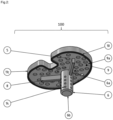
- Die Erfindung betrifft einen verbesserten Zementapplikator 100 zur Applikation von Knochenzement bei der Implantation von Prothesen.
- Dazu wird der Zementapplikator 100 eingesetzt, um Zement von einem Mischsystem in welchem sich der Zement vor seiner Verwendung befindet, auf die
- Oberfläche eines Knochens zu applizieren, damit anschließend eine Prothese auf dieser Oberfläche sicher verankert werden kann. Das Mischsystem, welches nicht Teil des eigentlichen Zementapplikators 100 ist, umfasst üblicherweise eine Knochenzementspritze 1 um den Knochenzement in einen Zementapplikator zu übertragen. Die Knochenzementspritze 1 weist normalweise eine Öffnung auf, durch welche der Knochenzement aus dem Mischsystem in einen Zementapplikator 100 austreten kann.
- Der Zementapplikator 100 umfasst wenigstens einen Universalanschluss 3 zum Anschluss an ein Mischsystem. Dieser Universalanschluss 3 ist dabei so ausgebildet, dass er mit einem Mischsystem verbindbar ist, sodass Knochenzement 2 aus einem Mischsystem durch den Universalanschluss 3 gepresst werden kann. Der Durchmesser des Universalanschlusses weist dabei bevorzugt einen Durchmesser zwischen 2 mm und 10 mm auf, sodass er für die meisten üblichen Mischsysteme geeignet ist. Der Universalanschluss ist dabei vorzugsweise so ausgebildet, dass der Zementapplikator entweder per Presssitz aufgedrückt, oder über ein bestehende Außengewinde des Düsenschraubaufsatzes des Mischsystems aufgeschraubt werden kann.
- Weiterhin umfasst der Zementapplikator 100 eine Vorkammer 11 aufweisend eine erste Seite 11a, eine zweite Seite 11b und einen Mantel 11c, der die ersten Seite 11a und die zweiten Seite 11b fluiddicht miteinander verbindet. Der Mantel 11c ist so ausgebildet, dass er das Innere der Vorkammer 11 dabei umschließt. Die Vorkammer 11 ist auf ihrer ersten Seite 11a mit dem Universalanschluss 3 fluiddurchströmbar verbunden und dient zu Aufnahme von Knochenzement aus einem Mischsystem.
- Zusätzlich umfasst die Vorkammer 11 auf der dem Universalanschluss 3 gegenüberliegenden zweiten Seite 11b wenigstens ein Austrittloch 5. Je nach Größe des finalen Implantats umfasst die Vorkammer 11 vorzugsweise zwischen 20 und 30 Austrittslöcher 5 mit einem Durchmesser zwischen 1 mm und 5 mm. In einer alternativen Ausführungsform sind die Austrittslöcher 5 schlitzförmig mit einer Länge von 2 cm bis 4 cm und einer breite zwischen 1 mm und 3 mm ausgeführt. Dabei weist die Vorkammer vorzugsweise zwischen 12 und 24 schlitzförmige Austrittslöcher 5 auf, durch welche der Knochenzement 2 aus der Vorkammer 11 gepresst werden kann.
- Weiterhin umfasst der Zementapplikator 100 einen Führungsdorn 6. Dieser ist an der zweiten Seite 11b der Vorkammer 11 so angeordnet, dass er mit einem ersten Ende 6a zentral in die Vorkammer 11 hineinragt und mit einem entgegengesetzten zweiten Ende 6b innerhalb eines präparierten Markraumkanals eines Knochens anbringbar ist.
- Der Führungsdorn 6 ist mit einem ersten Ende 6a vorzugweise kegelförmig ausgebildet und soll somit ein gleichmäßiges Einströmen des Fluids in die Vorkammer 11 gewährleisten. Damit ist er so ausgebildet, dass er den Verschluss eines Mischsystems durchstoßen kann, sodass Knochenzement aus dem Mischsystem über den Universalanschluss 3 in die Vorkammer 11 gelangen kann.
- In einer alternativen Ausführungsform ist der Führungsdorn 6 vorzugsweise fluiddurchströmbar ausgebildet und umfasst wenigstens ein Austrittsloch 14, sodass Knochenzement aus dem Mischsystem über den Universalanschluss 3 durch den Führungsdorn 6 über das wenigstens eine Austrittsloch 14 direkt in einen präparierten Markraumkanals gelangen kann. Das wenigstens eine Austrittsloch 14 ist dabei am zweiten Ende 6b angeordnet. Dabei umfasst der Führungsdorn vorzugsweise zwischen 10 und 20 Austrittslöcher 14 mit einer Größe von 0,5 mm bis 2 mm.
- Die genaue Geometrie des Führungsdorns 6 ist abhängig vom Implantat und der Implantatgröße. Vorzugsweise weisen dieser Führungsdorn bei Knieendoprothesen eine zylindrische Geometrie auf. Das Material ist vorzugsweise ein druckbarer Kunststoff, welcher werkseitig sterilisiert und steril verpackt werden kann. Dies ist beispielsweise Polyetheretherketon (PEEK).
- Der Zementapplikator 100 umfasst weiterhin wenigstens einen Austrittsbereich 9. Dieser ist über die zweite Seite 11b der Vorkammer mit der Vorkammer 11 verbunden und über wenigstens ein Austrittsloch 5 mit der Vorkammer 11 fluiddurchströmbar verbunden. Dabei bildet die zweite Seite 11b der Vorkammer 11 die erste Seite 9a des Austrittsbereichs 9. Weiterhin ist der Austrittsbereich 9 so ausgebildet, dass die mit ihrer der Vorkammer 11 gegenüberliegenden Seite offen und auf einem Knochen 7 anbringbar ist. So kann Knochenzement, von der Vorkammer 11 durch den Austrittsbereich 9 auf einem Knochen gleichmäßig aufgebracht werden.
- Der Applikator ist so aufgebaut, dass ein Operateur nach der Zementapplikation den Zementapplikator 100 entfernen und ein Implantat in den Knochenzement pressen kann.
- Dazu umfasst der Zementapplikator 100 wenigstens eine Torsionsschutzführung 8, sodass der flächig auf einem Knochen aufliegen kann. Diese ist dabei zwischen der Vorkammer 11 und dem Austrittsbereich 9 angeordnet. Die Torsionsschutzführung 8 ist speichenförmig vom Führungsdorn 6 ausgehend angeordnet. Diese kann dabei entweder einstückig mit dem Führungsdorn 6 oder separat ausgebildet sein. Die Torsionsschutzführung 8, übernimmt bei der Aufbringung des Knochenzements zwei Aufgaben. Die Torsionsschutzführung wird bei der Knochenzementapplikation in die bereits präparierten Schlitze im spongiösen Knochen eingeführt und verhindert somit ein verdrehen des Applikators um die longitudinale Achse des Knochens. Weiterhin soll bei der Zementapplikation kein Zement in diese Führungen gelangen. Durch einen passgenauen Sitz der Torsionsschutzführungen in den präparierten Schlitz, wirkt dieser zusätzlich abdichtend und verhindert somit das ungewollte Eindringen des Knochenzementes.
- In einer weiteren alternativen Ausführungsform weist der Austrittsbereich 9 eine sie umgegebene Dichtung 10 auf. Diese ist dabei so angeordnet, dass sie sich zwischen der Vorkammer 11 und dem Austrittsbereich 9 auf der dem Führungsdorn 6 abgewandten Seite des Mantels 11c befindet. Die Dichtung 10 ist dabei als Dichtlippe oder Dichtwulst ausgebildet und dient zur Verringerung der Kontaktfläche zwischen Austrittsbereich und Knochen. Hierdurch wird ein konstanter Druck innerhalb des Zements gewährleitet. Mit eben diesem gleichmäßigen Druck kann Knochenzement an jeder Stelle der Knochenoberfläche zeitgleich flächig eingebracht werden.
- In einer weiteren alternativen Ausführungsform umfasst der Zementapplikator 100 einen Druckregulierungswulst 12. Dieser ist vorzugsweise als Dichtungsring ausgeführt. Er ist ringförmig um den Führungsdorn 6 angeordnet und ragt dabei in die Vorkammer 11 hinein. Der Druckregulierungswulst 12 kann dabei entweder einstückig mit dem Führungsdorn 6 oder separat ausgebildet sein. Über die Dichtung 10 bzw. den Dichtungswulst 12 kann im Austrittsbereich 9 des Applikators die Dicke des Zementmantels auf dem Knochenplateau beeinflusst bzw. eingestellt werden.
- In einer weiteren Ausführungsform umfasst der Zementapplikator 100 noch wenigstens eine Stabilisierungsrippe 13. Diese ist auf dem Mantel 11c der Vorkammer angeordnet und dabei vom Führungsdorn 6 ausgehend zum Rand des Mantels 11c ausgerichtet. Sie dient dazu die Steifigkeit des Zementapplikator zu erhöhen. Alternativ kann dies erreicht werden, wenn die Materialdicke des Mantels 11c entsprechend erhöht wird.
- Die zusätzlichen Bauelemente der weiteren Ausführungsformen: wenigstens ein Austrittsloch 14, Dichtung 10, Druckregulierungswulst 12 und wenigstens eine Stabilisierungsrippe 13 sind miteinander kompatibel. So kann jedes dieser Bauelemente hinzugefügt oder wegelassen werden ohne die anderen Komponenten in ihrer Funktion zu beeinträchtigen. Welches Bauelement tatsächlich verwendet wird, hängt von der Art und der Größe des Implantates ab, für welches der Zementapplikator verwendet werden soll.
- Für die Verwendung des erfindungsgemäßen Zementapplikators 100 wird dieser zunächst an das verwendete Mischsystem über einen Universalanschluss 3 gesteckt, sodass der Zement 2 direkt hierdurch gespritzt werden kann. Durch einen internen zur Flussregulierung dienenden Führungsdorn 6 wird der Zement zunächst im Vorraum 11 gleichmäßig verteilt und tritt anschließend gleichmäßig über wenigstens ein unten liegendes Austrittsloch 5 aus. Hierdurch wird ein konstanter Druck des Knochenzements 2 gewährleitet. Mit eben diesem gleichmäßigen Druck wird der Knochenzement zeitgleich und flächig in den Knochen eingebracht. Über einen implantatindividuellen Führungsdorn 6 und eine Torsionsschutzführung 8 innerhalb des präparierten Markraumkanals des Knochens 7 wird zudem gewährleistet, dass der Zementapplikator 100 flächig auf dem Knochen 7 aufliegt. Nach der Zementapplikation kann der Operateur den Zementapplikator 100 entfernen und das Implantat in den Zement pressen. Über einen Dichtungsring bzw. einen Dichtungswulst kann zudem im Austrittsbereich 9 des Applikators 100 die Dicke des Zementmantels auf dem Schienbeinplateau beeinflusst bzw. eingestellt werden. Dies führt zur Erzeugung einer besonders gleichmäßigen Schicht von Knochenzement auf einem Knochen, sodass eine besonders zuverlässige Verbindung zwischen einen Knochen und einer implantierten Prothese sichergestellt.
- Der erfindungsgemäße Zementapplikator ist grundsätzlich für verschiedene Arten von Implantation geeignet bei denen Prothesen in Knochen mittels Knochenzement befestigt werden. Beispielhaft seien hier Operationen zum Ersetzen eines Hüftgelenks, eines Kniegelenks oder eines Schultergelenks genannt. Das Verfahren ist aber nicht darauf einschränkt. Dabei kann das Implantat aus verschiedensten Materialen oder Materialkombinationen bestehen. Beispielshafte Gruppen von Materialien sind Edelstähle, Titanverbindungen, Keramiken oder Kunststoffe. Dazu ist es notwendig den Zementapplikator an die jeweilige Gelenkgeometrie anzupassen.
- Eine beispielhafte Ausführung des Zementapplikators basiert auf der Geometrie der Tibiakomponente des P.F.C.™ SIGMAOTC3-Kniesystems (J&J Medical Devices). Nach intraoperativer Auswahl der finalen Größe, wird ein entsprechender Applikator ausgewählt, welcher der Geometrie und der Größe des zu verwendeten Implantats 1:1 entspricht - diese Passung wird dadurch realisiert, dass Hersteller, die einen solchen Applikator für die Implantation ihrer Implantate zur Verfügung stellen wollen, die 3D-Daten zur Verfügung stellen. Nach Präparation des Implantatlagers wird der Zement angerührt und anschließend das Mischsystem auf den Zementapplikator gesteckt/geschraubt. Der Führungsdorn wird in die präparierte Markhöhle eingeführt. Die Torsionsstellung wird in diesem konkreten Fall über die Torsionsschutzführung realisiert. Bei Implantaten, die keine Flügel aufweisen, wird eine mögliche Verdrehung des Implantats visuell kontrolliert. Abschließend wird der Zement durch das Mischsystem in den Applikator gepresst und verteilt sich über diesen gleichmäßig auf der präparierten Oberfläche des Kochens, die als Implantatlager dient.
-
-
Fig. 1 zeigt eine beispielhafte Ausführungsform des erfindungsgemäßen Zementapplikators 100 in einer isometrischen Ansicht. -
Fig. 2 zeigt eine beispielhafte Ausführungsform des erfindungsgemäßen Zementapplikators 100 im betriebsbereiten Zustand in einer isometrischen Ansicht. Hierbei ist der Zementapplikator 100 mit einem Mischsystem in Form einer Knochenzementspritze 1 mit Knochenzement 2 verbunden. DieFig.2 zeigt den Zementapplikator 100 wie dieser bereits über den Führungsdorn 6 im Knochen verankert wurde, um den Knochenzement 2 auf die Oberfläche des Knochens 7 zu applizieren. -
Fig. 3 zeigt eine beispielhafte Ausführungsform des erfindungsgemäßen Zementapplikators 100 zusammen mit einer mit Knochenzement 2 gefüllten Knochenzementspritze 1 und einem Knochen 7 auf dessen Oberfläche dieser Zement appliziert werden soll als Gesamtkonzept. -
- 1 Knochenzementspritze
- 2 (Knochen-)zement
- 3 Universalanschluss
- 4 Flussregulierungsdorn
- 5 Austrittsloch der Vorkammer
- 6 Führungsdorn
- 6a erstes Ende des Führungsdorns
- 6b zweites Ende des Führungsdorns
- 7 Knochen
- 8 Torsionsschutzführung
- 9 Austrittsbereich
- 9a erste Seite des Austrittsbereichs
- 9b zweite Seite des Austrittsbereichs
- 10 Dichtung
- 11 Vorkammer
- 11a erste Seite der Vorkammer
- 11b zweite Seite der Vorkammer
- 11c Mantel der Vorkammer
- 12 Druckregulierungswulst
- 13 Stabilisierungsrippe
- 14 Austrittsloch des Führungsdorns
- 100 Zementapplikator
Claims (5)
- Zementapplikator (100) zum Einbringen von Knochenzement bei der Implantation von Prothesen in Knochen wenigstens umfassend• einen Universalanschluss (3) zum Anschluss an ein Mischsystem• eine Vorkammer (11) aus einer ersten Seite (11a), einer zweiten Seite (11b) und einem Mantel (11c), der die erste Seite (11a) und die zweite Seite (11b) miteinander fluiddicht verbindet,• wobei die erste Seite (11a) mit dem Universalanschluss (3) fluiddurchströmbar verbindbar ist und zur Aufnahme von Knochenzement aus einem Mischsystem geeignet ist, und• wobei die zweite Seite (11b) der ersten Seite (11a) gegenüberliegend angeordnet ist und wenigstens ein Austrittloch (5) aufweist, durch welches der Knochenzement austreten kann,• ein Austrittsbereich (9), welcher benachbart zur Vorkammer (11) angeordnet ist, wobei die zweite Seite (11b) der Vorkammer die erste Seite (9a) der Austrittsbereich (9) bildet, sodass die Austrittsbereich (9) über das wenigstens eine Austrittsloch (5) mit der Vorkammer (9) fluiddurchströmbar verbunden ist, sodass Knochenzement von der Vorkammer (11) in die Austrittsbereich (9) strömen kann, wobei der Austrittsbereich (9) weiterhin so ausgebildet ist, dass seine der Vorkammer (11) gegenüberliegende zweite Seite (9b) offen und auf einem Knochen anordbar ist,• eine Torsionsschutzführung (8), wobei diese zwischen der Vorkammer (11) und der Austrittkammer (9) angeordnet ist, sodass der Zementapplikator (100) flächig auf einem Knochen aufliegt kann
dadurch gekennzeichnet, dass der Zementapplikator(100) weiterhin einen Führungsdorn (6) aufweist, welcher so angeordnet ist, dass er mit einem ersten Ende (6a) so in die Vorkammer (11) hineinragt, sodass er durch wenigstens einen Universalanschluss (3) hindurch einen Verschluss eines Mischsystems durchstoßen kann, sodass Knochenzement aus dem Mischsystem über den Universalanschluss (3) in die Vorkammer (11) gelangen kann, wobei ein dem ersten Ende entgegensetztes zweites Ende (6b) des Führungsdorns (6), innerhalb eines präparierten Markraumkanals eines Knochens anbringbar ist. - Zementapplikator (100) gemäß Anspruch 1 dadurch gekennzeichnet, dass der Führungsdorn (6) durchströmbar ausgebildet ist und wenigstens ein Austrittsloch (14) aufweist, sodass Knochenzement aus dem Mischsystem über den Universalanschluss (3) durch den Führungsdorn (6) über das wenigstens eine Austrittsloch (14) direkt in einen präparierten Markraumkanals gelangen kann.
- Zementapplikator (100) gemäß Anspruch 1 oder 2 dadurch gekennzeichnet, dass der Austrittsbereich (9) eine sie umgegebene Dichtung (10) aufweist, welche. so angeordnet ist, dass sie sich zwischen der Vorkammer (11) und dem Austrittsbereich (9) auf der dem Führungsdorn (6) abgewandten Seite des Mantels (11c) der Vorkammer befindet.
- Zementapplikator (100) gemäß einem der vorigen Ansprüche dadurch gekennzeichnet, dass der Zementapplikator (100) einen Druckregulierungswulst (12) aufweist, welcher ringförmig um den Führungsdorn (6) angeordnet ist und dabei in die Vorkammer (11) hineinragt.
- Zementapplikator (100) gemäß einem der vorigen Ansprüche dadurch gekennzeichnet, dass er noch wenigstens eine Stabilisierungsrippe (13) umfasst, wobei diese auf dem Mantel (11c) der Vorkammer angeordnet ist und dabei vom Führungsdorn (6) ausgehend zum Rand des Mantels (11c) ausgerichtet ist.
Priority Applications (1)
| Application Number | Priority Date | Filing Date | Title |
|---|---|---|---|
| EP22154210.3A EP4218636B1 (de) | 2022-01-31 | 2022-01-31 | Zementapplikator |
Applications Claiming Priority (1)
| Application Number | Priority Date | Filing Date | Title |
|---|---|---|---|
| EP22154210.3A EP4218636B1 (de) | 2022-01-31 | 2022-01-31 | Zementapplikator |
Publications (2)
| Publication Number | Publication Date |
|---|---|
| EP4218636A1 EP4218636A1 (de) | 2023-08-02 |
| EP4218636B1 true EP4218636B1 (de) | 2024-08-14 |
Family
ID=80123318
Family Applications (1)
| Application Number | Title | Priority Date | Filing Date |
|---|---|---|---|
| EP22154210.3A Active EP4218636B1 (de) | 2022-01-31 | 2022-01-31 | Zementapplikator |
Country Status (1)
| Country | Link |
|---|---|
| EP (1) | EP4218636B1 (de) |
Family Cites Families (4)
| Publication number | Priority date | Publication date | Assignee | Title |
|---|---|---|---|---|
| DE102007024083B4 (de) | 2007-02-01 | 2018-02-01 | Rudi Georg Bitsch | Zementapplikator |
| US9855085B2 (en) | 2013-06-28 | 2018-01-02 | AOD Holdings, LLC | Bone cement applicator |
| DE102016121607B4 (de) * | 2016-11-11 | 2019-05-16 | Heraeus Medical Gmbh | Vorrichtung und Verfahren zum Lagern und Mischen eines Knochenzements |
| DE102018209784A1 (de) * | 2018-06-18 | 2019-12-19 | Heraeus Medical Gmbh | Knochenzementapplikator mit versenkbarem Mischstab und Verfahren zur Herstellung eines Knochenzements |
-
2022
- 2022-01-31 EP EP22154210.3A patent/EP4218636B1/de active Active
Also Published As
| Publication number | Publication date |
|---|---|
| EP4218636A1 (de) | 2023-08-02 |
Similar Documents
| Publication | Publication Date | Title |
|---|---|---|
| EP0568552B1 (de) | Endoprothese des hüftgelenkes | |
| DE69527816T2 (de) | Schultergelenk-Endoprothese | |
| DE102011112890B4 (de) | Knochenschraube sowie Vorrichtung und Bausatz umfassend die Knochenschraube | |
| DE69715264T2 (de) | Knochenprothese | |
| DE69125712T2 (de) | Hüftprothese | |
| DE2610922A1 (de) | Schaft fuer kniegelenk-endoprothesen | |
| EP0085147B1 (de) | Gerader, blattartiger Schaft für eine Gelenkendoprothese | |
| DE3142730A1 (de) | "gelenkprothese" | |
| DE2220304A1 (de) | Hueftgelenkprothese, operationsverfahren zum einsetzen dieser prothese, sowie werkzeugsatz zur ausfuehrung des operationsverfahrens | |
| EP2124783A2 (de) | Implantat zur frakturversorgung | |
| DD301734A9 (de) | Verankerungselement zum halten eines kuenstlichen gelenkteils | |
| DE10233204A1 (de) | Zementierbare Hüftgelenkendoprothese als Ersatz des proximalen Femur | |
| EP3923840A1 (de) | Knochenverankerungsvorrichtung für den pedikelzugang | |
| EP4226897B1 (de) | Augmentationsvorrichtung | |
| CH659580A5 (de) | Den grossen trochanter ersetzendes implantat. | |
| EP3490504B1 (de) | Implantat und gelenkimplantat | |
| EP4218636B1 (de) | Zementapplikator | |
| DE102007024083B4 (de) | Zementapplikator | |
| DE102015109353A1 (de) | Gelenkteil und Kniegelenkendoprothese | |
| EP1592369A1 (de) | Hüftgelenkprothese mit einem in den oberschenkelknochen ein zusetzenden schaft | |
| EP3542761B1 (de) | Tibia-komponente eines künstlichen kniegelenks | |
| DE60219352T2 (de) | Set aus femurschäften, die mit einer durch ihre mitte injizierten flüssigkeit fixiert werden | |
| DE102010042082B4 (de) | Set zur Erstellung eines transkutanen Implantates | |
| EP3666229B1 (de) | Kniegelenkendoprothesen-satz und instrumentarium | |
| EP3831344A1 (de) | Siegel zur applikation von knochenzement |
Legal Events
| Date | Code | Title | Description |
|---|---|---|---|
| PUAI | Public reference made under article 153(3) epc to a published international application that has entered the european phase |
Free format text: ORIGINAL CODE: 0009012 |
|
| STAA | Information on the status of an ep patent application or granted ep patent |
Free format text: STATUS: THE APPLICATION HAS BEEN PUBLISHED |
|
| AK | Designated contracting states |
Kind code of ref document: A1 Designated state(s): AL AT BE BG CH CY CZ DE DK EE ES FI FR GB GR HR HU IE IS IT LI LT LU LV MC MK MT NL NO PL PT RO RS SE SI SK SM TR |
|
| STAA | Information on the status of an ep patent application or granted ep patent |
Free format text: STATUS: REQUEST FOR EXAMINATION WAS MADE |
|
| RIN1 | Information on inventor provided before grant (corrected) |
Inventor name: JAHNKE, ALEXANDER Inventor name: HARZ, TORBEN Inventor name: FONSECA-ULLOA, CARLOS ALFONSO Inventor name: FOELSCH, CHRISTIAN |
|
| 17P | Request for examination filed |
Effective date: 20240202 |
|
| RBV | Designated contracting states (corrected) |
Designated state(s): AL AT BE BG CH CY CZ DE DK EE ES FI FR GB GR HR HU IE IS IT LI LT LU LV MC MK MT NL NO PL PT RO RS SE SI SK SM TR |
|
| GRAP | Despatch of communication of intention to grant a patent |
Free format text: ORIGINAL CODE: EPIDOSNIGR1 |
|
| STAA | Information on the status of an ep patent application or granted ep patent |
Free format text: STATUS: GRANT OF PATENT IS INTENDED |
|
| RIC1 | Information provided on ipc code assigned before grant |
Ipc: A61F 2/36 20060101ALI20240221BHEP Ipc: A61B 17/88 20060101AFI20240221BHEP |
|
| INTG | Intention to grant announced |
Effective date: 20240319 |
|
| GRAS | Grant fee paid |
Free format text: ORIGINAL CODE: EPIDOSNIGR3 |
|
| GRAA | (expected) grant |
Free format text: ORIGINAL CODE: 0009210 |
|
| STAA | Information on the status of an ep patent application or granted ep patent |
Free format text: STATUS: THE PATENT HAS BEEN GRANTED |
|
| RAP3 | Party data changed (applicant data changed or rights of an application transferred) |
Owner name: JUSTUS-LIEBIG-UNIVERSITAET GIESSEN,KOERPERSCHAFT DES OEFFENTLICHEN RECHTS |
|
| AK | Designated contracting states |
Kind code of ref document: B1 Designated state(s): AL AT BE BG CH CY CZ DE DK EE ES FI FR GB GR HR HU IE IS IT LI LT LU LV MC MK MT NL NO PL PT RO RS SE SI SK SM TR |
|
| REG | Reference to a national code |
Ref country code: GB Ref legal event code: FG4D Free format text: NOT ENGLISH |
|
| REG | Reference to a national code |
Ref country code: CH Ref legal event code: EP |
|
| REG | Reference to a national code |
Ref country code: DE Ref legal event code: R096 Ref document number: 502022001424 Country of ref document: DE |
|
| REG | Reference to a national code |
Ref country code: IE Ref legal event code: FG4D Free format text: LANGUAGE OF EP DOCUMENT: GERMAN |
|
| REG | Reference to a national code |
Ref country code: LT Ref legal event code: MG9D |
|
| REG | Reference to a national code |
Ref country code: NL Ref legal event code: MP Effective date: 20240814 |
|
| PG25 | Lapsed in a contracting state [announced via postgrant information from national office to epo] |
Ref country code: NO Free format text: LAPSE BECAUSE OF FAILURE TO SUBMIT A TRANSLATION OF THE DESCRIPTION OR TO PAY THE FEE WITHIN THE PRESCRIBED TIME-LIMIT Effective date: 20241114 |
|
| PG25 | Lapsed in a contracting state [announced via postgrant information from national office to epo] |
Ref country code: PT Free format text: LAPSE BECAUSE OF FAILURE TO SUBMIT A TRANSLATION OF THE DESCRIPTION OR TO PAY THE FEE WITHIN THE PRESCRIBED TIME-LIMIT Effective date: 20241216 Ref country code: NL Free format text: LAPSE BECAUSE OF FAILURE TO SUBMIT A TRANSLATION OF THE DESCRIPTION OR TO PAY THE FEE WITHIN THE PRESCRIBED TIME-LIMIT Effective date: 20240814 Ref country code: GR Free format text: LAPSE BECAUSE OF FAILURE TO SUBMIT A TRANSLATION OF THE DESCRIPTION OR TO PAY THE FEE WITHIN THE PRESCRIBED TIME-LIMIT Effective date: 20241115 Ref country code: PL Free format text: LAPSE BECAUSE OF FAILURE TO SUBMIT A TRANSLATION OF THE DESCRIPTION OR TO PAY THE FEE WITHIN THE PRESCRIBED TIME-LIMIT Effective date: 20240814 Ref country code: FI Free format text: LAPSE BECAUSE OF FAILURE TO SUBMIT A TRANSLATION OF THE DESCRIPTION OR TO PAY THE FEE WITHIN THE PRESCRIBED TIME-LIMIT Effective date: 20240814 |
|
| PG25 | Lapsed in a contracting state [announced via postgrant information from national office to epo] |
Ref country code: BG Free format text: LAPSE BECAUSE OF FAILURE TO SUBMIT A TRANSLATION OF THE DESCRIPTION OR TO PAY THE FEE WITHIN THE PRESCRIBED TIME-LIMIT Effective date: 20240814 |
|
| PG25 | Lapsed in a contracting state [announced via postgrant information from national office to epo] |
Ref country code: LV Free format text: LAPSE BECAUSE OF FAILURE TO SUBMIT A TRANSLATION OF THE DESCRIPTION OR TO PAY THE FEE WITHIN THE PRESCRIBED TIME-LIMIT Effective date: 20240814 |
|
| PG25 | Lapsed in a contracting state [announced via postgrant information from national office to epo] |
Ref country code: IS Free format text: LAPSE BECAUSE OF FAILURE TO SUBMIT A TRANSLATION OF THE DESCRIPTION OR TO PAY THE FEE WITHIN THE PRESCRIBED TIME-LIMIT Effective date: 20241214 |
|
| PG25 | Lapsed in a contracting state [announced via postgrant information from national office to epo] |
Ref country code: HR Free format text: LAPSE BECAUSE OF FAILURE TO SUBMIT A TRANSLATION OF THE DESCRIPTION OR TO PAY THE FEE WITHIN THE PRESCRIBED TIME-LIMIT Effective date: 20240814 |
|
| PG25 | Lapsed in a contracting state [announced via postgrant information from national office to epo] |
Ref country code: RS Free format text: LAPSE BECAUSE OF FAILURE TO SUBMIT A TRANSLATION OF THE DESCRIPTION OR TO PAY THE FEE WITHIN THE PRESCRIBED TIME-LIMIT Effective date: 20241114 Ref country code: ES Free format text: LAPSE BECAUSE OF FAILURE TO SUBMIT A TRANSLATION OF THE DESCRIPTION OR TO PAY THE FEE WITHIN THE PRESCRIBED TIME-LIMIT Effective date: 20240814 |
|
| PG25 | Lapsed in a contracting state [announced via postgrant information from national office to epo] |
Ref country code: RS Free format text: LAPSE BECAUSE OF FAILURE TO SUBMIT A TRANSLATION OF THE DESCRIPTION OR TO PAY THE FEE WITHIN THE PRESCRIBED TIME-LIMIT Effective date: 20241114 Ref country code: PT Free format text: LAPSE BECAUSE OF FAILURE TO SUBMIT A TRANSLATION OF THE DESCRIPTION OR TO PAY THE FEE WITHIN THE PRESCRIBED TIME-LIMIT Effective date: 20241216 Ref country code: PL Free format text: LAPSE BECAUSE OF FAILURE TO SUBMIT A TRANSLATION OF THE DESCRIPTION OR TO PAY THE FEE WITHIN THE PRESCRIBED TIME-LIMIT Effective date: 20240814 Ref country code: NO Free format text: LAPSE BECAUSE OF FAILURE TO SUBMIT A TRANSLATION OF THE DESCRIPTION OR TO PAY THE FEE WITHIN THE PRESCRIBED TIME-LIMIT Effective date: 20241114 Ref country code: NL Free format text: LAPSE BECAUSE OF FAILURE TO SUBMIT A TRANSLATION OF THE DESCRIPTION OR TO PAY THE FEE WITHIN THE PRESCRIBED TIME-LIMIT Effective date: 20240814 Ref country code: LV Free format text: LAPSE BECAUSE OF FAILURE TO SUBMIT A TRANSLATION OF THE DESCRIPTION OR TO PAY THE FEE WITHIN THE PRESCRIBED TIME-LIMIT Effective date: 20240814 Ref country code: IS Free format text: LAPSE BECAUSE OF FAILURE TO SUBMIT A TRANSLATION OF THE DESCRIPTION OR TO PAY THE FEE WITHIN THE PRESCRIBED TIME-LIMIT Effective date: 20241214 Ref country code: HR Free format text: LAPSE BECAUSE OF FAILURE TO SUBMIT A TRANSLATION OF THE DESCRIPTION OR TO PAY THE FEE WITHIN THE PRESCRIBED TIME-LIMIT Effective date: 20240814 Ref country code: GR Free format text: LAPSE BECAUSE OF FAILURE TO SUBMIT A TRANSLATION OF THE DESCRIPTION OR TO PAY THE FEE WITHIN THE PRESCRIBED TIME-LIMIT Effective date: 20241115 Ref country code: FI Free format text: LAPSE BECAUSE OF FAILURE TO SUBMIT A TRANSLATION OF THE DESCRIPTION OR TO PAY THE FEE WITHIN THE PRESCRIBED TIME-LIMIT Effective date: 20240814 Ref country code: ES Free format text: LAPSE BECAUSE OF FAILURE TO SUBMIT A TRANSLATION OF THE DESCRIPTION OR TO PAY THE FEE WITHIN THE PRESCRIBED TIME-LIMIT Effective date: 20240814 Ref country code: BG Free format text: LAPSE BECAUSE OF FAILURE TO SUBMIT A TRANSLATION OF THE DESCRIPTION OR TO PAY THE FEE WITHIN THE PRESCRIBED TIME-LIMIT Effective date: 20240814 |
|
| PG25 | Lapsed in a contracting state [announced via postgrant information from national office to epo] |
Ref country code: RO Free format text: LAPSE BECAUSE OF FAILURE TO SUBMIT A TRANSLATION OF THE DESCRIPTION OR TO PAY THE FEE WITHIN THE PRESCRIBED TIME-LIMIT Effective date: 20240814 Ref country code: DK Free format text: LAPSE BECAUSE OF FAILURE TO SUBMIT A TRANSLATION OF THE DESCRIPTION OR TO PAY THE FEE WITHIN THE PRESCRIBED TIME-LIMIT Effective date: 20240814 Ref country code: SM Free format text: LAPSE BECAUSE OF FAILURE TO SUBMIT A TRANSLATION OF THE DESCRIPTION OR TO PAY THE FEE WITHIN THE PRESCRIBED TIME-LIMIT Effective date: 20240814 |
|
| PG25 | Lapsed in a contracting state [announced via postgrant information from national office to epo] |
Ref country code: EE Free format text: LAPSE BECAUSE OF FAILURE TO SUBMIT A TRANSLATION OF THE DESCRIPTION OR TO PAY THE FEE WITHIN THE PRESCRIBED TIME-LIMIT Effective date: 20240814 |
|
| PG25 | Lapsed in a contracting state [announced via postgrant information from national office to epo] |
Ref country code: CZ Free format text: LAPSE BECAUSE OF FAILURE TO SUBMIT A TRANSLATION OF THE DESCRIPTION OR TO PAY THE FEE WITHIN THE PRESCRIBED TIME-LIMIT Effective date: 20240814 |
|
| PG25 | Lapsed in a contracting state [announced via postgrant information from national office to epo] |
Ref country code: SK Free format text: LAPSE BECAUSE OF FAILURE TO SUBMIT A TRANSLATION OF THE DESCRIPTION OR TO PAY THE FEE WITHIN THE PRESCRIBED TIME-LIMIT Effective date: 20240814 Ref country code: IT Free format text: LAPSE BECAUSE OF FAILURE TO SUBMIT A TRANSLATION OF THE DESCRIPTION OR TO PAY THE FEE WITHIN THE PRESCRIBED TIME-LIMIT Effective date: 20240814 |
|
| REG | Reference to a national code |
Ref country code: DE Ref legal event code: R097 Ref document number: 502022001424 Country of ref document: DE |
|
| PLBE | No opposition filed within time limit |
Free format text: ORIGINAL CODE: 0009261 |
|
| STAA | Information on the status of an ep patent application or granted ep patent |
Free format text: STATUS: NO OPPOSITION FILED WITHIN TIME LIMIT |
|
| 26N | No opposition filed |
Effective date: 20250515 |
|
| REG | Reference to a national code |
Ref country code: CH Ref legal event code: PL |
|
| PG25 | Lapsed in a contracting state [announced via postgrant information from national office to epo] |
Ref country code: SE Free format text: LAPSE BECAUSE OF FAILURE TO SUBMIT A TRANSLATION OF THE DESCRIPTION OR TO PAY THE FEE WITHIN THE PRESCRIBED TIME-LIMIT Effective date: 20240814 |
|
| PG25 | Lapsed in a contracting state [announced via postgrant information from national office to epo] |
Ref country code: LU Free format text: LAPSE BECAUSE OF NON-PAYMENT OF DUE FEES Effective date: 20250131 Ref country code: MC Free format text: LAPSE BECAUSE OF FAILURE TO SUBMIT A TRANSLATION OF THE DESCRIPTION OR TO PAY THE FEE WITHIN THE PRESCRIBED TIME-LIMIT Effective date: 20240814 |
|
| PG25 | Lapsed in a contracting state [announced via postgrant information from national office to epo] |
Ref country code: BE Free format text: LAPSE BECAUSE OF NON-PAYMENT OF DUE FEES Effective date: 20250131 |
|
| PG25 | Lapsed in a contracting state [announced via postgrant information from national office to epo] |
Ref country code: FR Free format text: LAPSE BECAUSE OF NON-PAYMENT OF DUE FEES Effective date: 20250131 |
|
| PG25 | Lapsed in a contracting state [announced via postgrant information from national office to epo] |
Ref country code: CH Free format text: LAPSE BECAUSE OF NON-PAYMENT OF DUE FEES Effective date: 20250131 |
|
| REG | Reference to a national code |
Ref country code: BE Ref legal event code: MM Effective date: 20250131 |
|
| PG25 | Lapsed in a contracting state [announced via postgrant information from national office to epo] |
Ref country code: IE Free format text: LAPSE BECAUSE OF NON-PAYMENT OF DUE FEES Effective date: 20250131 |
|
| PGFP | Annual fee paid to national office [announced via postgrant information from national office to epo] |
Ref country code: DE Payment date: 20260131 Year of fee payment: 5 |
|
| PGFP | Annual fee paid to national office [announced via postgrant information from national office to epo] |
Ref country code: AT Payment date: 20260301 Year of fee payment: 5 |