EP3888946B1 - Pneumatique - Google Patents
Pneumatique Download PDFInfo
- Publication number
- EP3888946B1 EP3888946B1 EP20020140.8A EP20020140A EP3888946B1 EP 3888946 B1 EP3888946 B1 EP 3888946B1 EP 20020140 A EP20020140 A EP 20020140A EP 3888946 B1 EP3888946 B1 EP 3888946B1
- Authority
- EP
- European Patent Office
- Prior art keywords
- groove
- snow
- tyre
- longitudinal direction
- tyre according
- Prior art date
- Legal status (The legal status is an assumption and is not a legal conclusion. Google has not performed a legal analysis and makes no representation as to the accuracy of the status listed.)
- Active
Links
Images


Classifications
-
- B—PERFORMING OPERATIONS; TRANSPORTING
- B60—VEHICLES IN GENERAL
- B60C—VEHICLE TYRES; TYRE INFLATION; TYRE CHANGING; CONNECTING VALVES TO INFLATABLE ELASTIC BODIES IN GENERAL; DEVICES OR ARRANGEMENTS RELATED TO TYRES
- B60C11/00—Tyre tread bands; Tread patterns; Anti-skid inserts
- B60C11/03—Tread patterns
- B60C11/0306—Patterns comprising block rows or discontinuous ribs
- B60C11/0309—Patterns comprising block rows or discontinuous ribs further characterised by the groove cross-section
-
- B—PERFORMING OPERATIONS; TRANSPORTING
- B60—VEHICLES IN GENERAL
- B60C—VEHICLE TYRES; TYRE INFLATION; TYRE CHANGING; CONNECTING VALVES TO INFLATABLE ELASTIC BODIES IN GENERAL; DEVICES OR ARRANGEMENTS RELATED TO TYRES
- B60C11/00—Tyre tread bands; Tread patterns; Anti-skid inserts
- B60C11/03—Tread patterns
- B60C11/0302—Tread patterns directional pattern, i.e. with main rolling direction
-
- B—PERFORMING OPERATIONS; TRANSPORTING
- B60—VEHICLES IN GENERAL
- B60C—VEHICLE TYRES; TYRE INFLATION; TYRE CHANGING; CONNECTING VALVES TO INFLATABLE ELASTIC BODIES IN GENERAL; DEVICES OR ARRANGEMENTS RELATED TO TYRES
- B60C11/00—Tyre tread bands; Tread patterns; Anti-skid inserts
- B60C11/03—Tread patterns
- B60C11/032—Patterns comprising isolated recesses
- B60C11/0323—Patterns comprising isolated recesses tread comprising channels under the tread surface, e.g. for draining water
-
- B—PERFORMING OPERATIONS; TRANSPORTING
- B60—VEHICLES IN GENERAL
- B60C—VEHICLE TYRES; TYRE INFLATION; TYRE CHANGING; CONNECTING VALVES TO INFLATABLE ELASTIC BODIES IN GENERAL; DEVICES OR ARRANGEMENTS RELATED TO TYRES
- B60C11/00—Tyre tread bands; Tread patterns; Anti-skid inserts
- B60C11/03—Tread patterns
- B60C11/12—Tread patterns characterised by the use of narrow slits or incisions, e.g. sipes
- B60C11/1272—Width of the sipe
- B60C11/1281—Width of the sipe different within the same sipe, i.e. enlarged width portion at sipe bottom or along its length
-
- B—PERFORMING OPERATIONS; TRANSPORTING
- B60—VEHICLES IN GENERAL
- B60C—VEHICLE TYRES; TYRE INFLATION; TYRE CHANGING; CONNECTING VALVES TO INFLATABLE ELASTIC BODIES IN GENERAL; DEVICES OR ARRANGEMENTS RELATED TO TYRES
- B60C11/00—Tyre tread bands; Tread patterns; Anti-skid inserts
- B60C11/03—Tread patterns
- B60C11/13—Tread patterns characterised by the groove cross-section, e.g. for buttressing or preventing stone-trapping
- B60C11/1353—Tread patterns characterised by the groove cross-section, e.g. for buttressing or preventing stone-trapping with special features of the groove bottom
-
- B—PERFORMING OPERATIONS; TRANSPORTING
- B60—VEHICLES IN GENERAL
- B60C—VEHICLE TYRES; TYRE INFLATION; TYRE CHANGING; CONNECTING VALVES TO INFLATABLE ELASTIC BODIES IN GENERAL; DEVICES OR ARRANGEMENTS RELATED TO TYRES
- B60C11/00—Tyre tread bands; Tread patterns; Anti-skid inserts
- B60C11/03—Tread patterns
- B60C11/13—Tread patterns characterised by the groove cross-section, e.g. for buttressing or preventing stone-trapping
- B60C11/1369—Tie bars for linking block elements and bridging the groove
-
- B—PERFORMING OPERATIONS; TRANSPORTING
- B60—VEHICLES IN GENERAL
- B60C—VEHICLE TYRES; TYRE INFLATION; TYRE CHANGING; CONNECTING VALVES TO INFLATABLE ELASTIC BODIES IN GENERAL; DEVICES OR ARRANGEMENTS RELATED TO TYRES
- B60C11/00—Tyre tread bands; Tread patterns; Anti-skid inserts
- B60C11/03—Tread patterns
- B60C2011/0337—Tread patterns characterised by particular design features of the pattern
- B60C2011/0339—Grooves
- B60C2011/0358—Lateral grooves, i.e. having an angle of 45 to 90 degees to the equatorial plane
-
- B—PERFORMING OPERATIONS; TRANSPORTING
- B60—VEHICLES IN GENERAL
- B60C—VEHICLE TYRES; TYRE INFLATION; TYRE CHANGING; CONNECTING VALVES TO INFLATABLE ELASTIC BODIES IN GENERAL; DEVICES OR ARRANGEMENTS RELATED TO TYRES
- B60C11/00—Tyre tread bands; Tread patterns; Anti-skid inserts
- B60C11/03—Tread patterns
- B60C11/12—Tread patterns characterised by the use of narrow slits or incisions, e.g. sipes
- B60C11/1204—Tread patterns characterised by the use of narrow slits or incisions, e.g. sipes with special shape of the sipe
- B60C2011/1213—Tread patterns characterised by the use of narrow slits or incisions, e.g. sipes with special shape of the sipe sinusoidal or zigzag at the tread surface
-
- B—PERFORMING OPERATIONS; TRANSPORTING
- B60—VEHICLES IN GENERAL
- B60C—VEHICLE TYRES; TYRE INFLATION; TYRE CHANGING; CONNECTING VALVES TO INFLATABLE ELASTIC BODIES IN GENERAL; DEVICES OR ARRANGEMENTS RELATED TO TYRES
- B60C11/00—Tyre tread bands; Tread patterns; Anti-skid inserts
- B60C11/03—Tread patterns
- B60C11/13—Tread patterns characterised by the groove cross-section, e.g. for buttressing or preventing stone-trapping
- B60C11/1307—Tread patterns characterised by the groove cross-section, e.g. for buttressing or preventing stone-trapping with special features of the groove walls
- B60C2011/1338—Tread patterns characterised by the groove cross-section, e.g. for buttressing or preventing stone-trapping with special features of the groove walls comprising protrusions
-
- B—PERFORMING OPERATIONS; TRANSPORTING
- B60—VEHICLES IN GENERAL
- B60C—VEHICLE TYRES; TYRE INFLATION; TYRE CHANGING; CONNECTING VALVES TO INFLATABLE ELASTIC BODIES IN GENERAL; DEVICES OR ARRANGEMENTS RELATED TO TYRES
- B60C11/00—Tyre tread bands; Tread patterns; Anti-skid inserts
- B60C11/03—Tread patterns
- B60C11/13—Tread patterns characterised by the groove cross-section, e.g. for buttressing or preventing stone-trapping
- B60C11/1353—Tread patterns characterised by the groove cross-section, e.g. for buttressing or preventing stone-trapping with special features of the groove bottom
- B60C2011/1361—Tread patterns characterised by the groove cross-section, e.g. for buttressing or preventing stone-trapping with special features of the groove bottom with protrusions extending from the groove bottom
Definitions
- the present invention relates to tyres, and more particularly to snow tyres.
- European patent no. 3100873 discloses a tyre with protrusions located on the bottom wall of a groove in the tyre tread. The protrusions are intended to improve grip on snow without greatly affecting water flow.
- KR1020040104118A discloses a tyre with a device in a groove to prevent the snow entering the groove. However, these arrangements leave room for improvement. Attention is also drawn to the disclosures of WO2011/073312A1 , FR3026347A1 , DE102011051224A1 and EP2591923A2 .
- the present invention aims to mitigate at least one problem of the prior art.
- the present invention provides a tyre as claimed in claim 1.
- the first surface acts to trap snow flowing from the first side
- the second surface acts to allow water to flow smoothly round the snow trapping device.
- the snow trapped by the first surface has two effects: firstly, some of the snow sliding in the groove encounters the first surface which stops the snow sliding any further; secondly, other of the snow, which is above the snow trapping device, does not encounter the first surface but is subject shear stress from the snow that has been trapped. The shear stress slows the sliding of that portion of snow.
- the overall effect is to slow down the whole pack of snow which improves snow compression and overall grip.
- Prior art snow trapping devices tend to cause flow separation and recirculation downstream of the device, which results in increased hydrodynamic drag and flow losses and reduced water drainage.
- the passageway for water through the device reduces flow separation and recirculation downstream of the device, thereby improving water flow and drainage.
- the water flow encountering the device is divided into two main flows. One is channelled inside the passageway, and the other flows over the snow trapping device. The flow channelled inside the passageway creates a water pressure gradient which reduces creation of the recirculation region.
- KR1020040104118A discloses a tyre with device in a groove to prevent snow entering the groove.
- the device is positioned in a circumferential direction groove and a width direction groove at the point where the two grooves cross each other. According to Fig. 2 , only a small portion of the device is positioned between the side walls of either groove, and most is positioned at the intersection of the grooves. This means that the device blocks water flow along both intersecting grooves. In contrast, the device of the present invention does not block the water flow so much. By providing that at least half of the device is positioned between the side walls of the groove in a plan view of the tread, water drainage is improved because less of the intersection between two grooves is blocked.
- the device of KR1020040104118A blocks most of the intersection point, the amount of snow that can be diverted will be limited.
- the device, or snow trapped by the device in the groove can divert more snow into an intersecting groove at the intersection point, thereby improving grip on snow.
- the feature that the snow trapping device extends at most halfway across the area of the groove may be provided.
- This feature provides improved water drainage in comparison to the prior art, for the following reasons.
- the device extends more than halfway across the area of the groove from the bottom wall of the groove. This means the device provides a large blocking effect on water flowing in the groove, which reduces drainage.
- the snow trapping device extending at most 50% of the way across the area of the groove, the device does not block so much of the area of the groove, which improves water drainage.
- the joining or contact point may be formed at the apex of the snow trapping device.
- a sipe is provided at the contact point which allows the parts to contact each other. The sipe opens when the snow trapping device is outside the contact patch, and closes when the snow trapping device enters the contact patch.
- the sipe may be at the apex of the snow trapping device.
- the parts which overlap may be joined to each other by being integrally formed at the joining point.
- the parts which overlap are joined to each other so that a joining point is formed between the passageway and the bottom wall of the groove.
- a joining point is formed between the passageway and the bottom wall of the groove.
- an "inner” joining point may be formed.
- the parts may be integrally formed at the "inner” contact point.
- the parts of the device which overlap in the groove longitudinal direction are integrally formed.
- the parts of the device which overlap in the groove longitudinal direction extend along the groove longitudinal direction from the same start point, and preferably to the same end point.
- the passageway comprises a hole in the device.
- a maximum dimension of the hole orthogonal to the groove longitudinal direction is less than half the depth of the snow trapping device.
- a maximum dimension of the hole may be preferably less than 1mm, when for example the depth of the snow trapping device is 2mm and, for example, the depth of the groove is 8mm. This helps to prevent snow passing through the hole.
- the hole may be circular in cross-section.
- the passageway comprises a sipe.
- a sipe is a groove that closes when it passes through the contact patch of the tyre.
- the sipe is formed outside the hole in a tyre radial direction, and adjoins the hole.
- the sipe helps to simplify the manufacturing process by allowing the hole to be formed more easily during moulding of the tyre.
- the passageway is substantially parallel with the groove longitudinal direction.
- the passageway is substantially parallel with the groove longitudinal direction.
- the passageway follows the flow streamline, which reduces resistance to flow.
- the passageway comprises a hole formed in the second surface.
- the passageway comprises a hole formed the first surface.
- the passageway may have a substantially constant cross-sectional area along its length.
- the snow trapping device is attached to a bottom wall and a side wall of the groove.
- the snow trapping device is attached to both a bottom wall and a side wall of the groove.
- the snow trapping device is attached to both a bottom wall and a side wall of the groove means that the device is securely attached and is less likely to become detached from the groove than in the prior art.
- the protrusions are only attached to the bottom wall of the groove.
- the snow trapping device is attached to both side walls of the groove.
- the second surface is inclined by less than 45°, more preferably less than 30°, with respect to the bottom wall of the groove. This avoids abrupt changes of direction of the water flow to provide a smooth flow.
- the second surface directs water flowing from the second side outwards in a tyre radial direction.
- the second (inclined) surface directs water flowing from the second side away from the bottom wall of the groove.
- At least half of the first (snow trapping) surface of the device (which may be in more than one part) when viewed along the groove width direction does not face outwards in the tyre radial direction. This means the snow is not directed outwards in the tyre radial direction and is trapped more effectively.
- the apex of the snow trapping device extends from one side wall to the other at a constant height.
- the first (snow trapping) surface extends in a direction which is substantially parallel to the groove width direction. This helps to trap snow more effectively.
- the first (snow trapping) surface extends at a right angle to the bottom wall and/or a side wall of the groove. This helps to trap snow more effectively.
- the first surface is planar.
- the first (snow trapping) surface which is planar is normal to the groove longitudinal direction.
- the second surface is planar.
- the groove is a width direction groove.
- width direction groove means the groove extends in the width direction, but does not need to extend exactly parallel to the width direction.
- the snow trapping device improves grip during cornering, when the snow tries to slide in the tyre width direction.
- the groove is provided in the tyre shoulder region.
- “Tyre shoulder region” means the region between the tread end and a point halfway to the tyre equatorial plane from the tread end.
- the tyre is a pneumatic tyre.
- the tyre is a snow tyre or an allseason tyre.
- the tyre in a plan view of the tread, has a V-shaped groove, and the snow trapping device is located in the V-shaped groove.
- the first side is the outside in the tyre width direction.
- the second side is the inside in the tyre width direction.
- “Outside” means outside with respect to the tyre equatorial plane.
- the second surface allows water to flow smoothly round the snow trapping device towards the outside with respect to the tyre equatorial plane. This is the predominant flow direction of water drainage in the width direction grooves.
- the depth of the snow trapping device is at least 25% or at least 30% of the depth of the groove.
- the snow trapping device occupies at least 25% or at least 30% of the area of the groove.
- the device when viewed in the groove longitudinal direction, the device occupies at most 50% of the area of the groove, more preferably at most 40%, more preferably at most 30%.
- the device when viewed in the groove longitudinal direction, the device extends at most halfway across the area of the groove from the bottom wall of the groove.
- the device extends more than halfway across the area of the groove from the bottom wall of the groove. This means the device provides a large blocking effect on water flowing in the groove, which reduces drainage.
- the snow trapping device extending at most 50% of the way across the area of the groove, the device does not block so much of the area of the groove, which improves water drainage.
- the device extends across at most at most 40% of the way across the area of the groove from the bottom wall of the groove, more preferably at most 30%.
- the depth of the device is at most 50% of the depth of the groove, mere preferably at most 40%, more preferably at most 30%.
- the device occupies or extends across less of the area of the groove in this way, the device provides less hindrance to the flow of water along the groove. Also, restricting the depth of the device helps to improve fatigue resistance and wear resistance. This is because the device is less likely to contact the road surface during running.
- a maximum dimension of the passageway orthogonal to the groove longitudinal direction is less than half the depth of the snow trapping device.
- a maximum dimension of the passageway may be preferably less than 1mm, when for example the depth of the snow trapping device is 2mm and, for example, the depth of the groove is 8mm. This helps to prevent snow passing through the passageway.
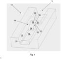
- the tread 10 has a groove (lug) 12 having a snow trapping device in the form of a dam 14 in it.
- the snow trapping device 14 is adjacent to, and attached to, a bottom wall 16 of the groove 12, as well as being adjacent to and attached to a left-hand side wall 18 and a right-hand side wall 20 of the groove 12.
- the groove 12 and snow trapping device 14 are shown when they are not in the contact patch of the tyre.
- the dam 14 has a first, snow trapping surface 22 facing a first side in the groove longitudinal direction.
- the first side of the dam 14 is towards the top of Fig. 1 .
- the first, snow trapping surface 22 is configured to trap snow flowing from the first side in the groove longitudinal direction.
- the dam 14 has a second, inclined surface 24 facing a second side in the groove longitudinal direction which is opposite to the first side.
- the second side of the dam 14 is towards the bottom of Fig. 1 .
- the second, inclined surface 24 is inclined so as to direct water flowing from the second side away from the wall to which the snow trapping device is adjacent.
- the surface 24 is inclined with respect to the bottom wall 16 of the groove 12, and directs the flow of water away from the bottom wall 16. The surface 24 does not direct the flow of water away from the side walls 18 and 20 of the groove 12.
- the dam 14 has a left-hand part 26 and a right-hand part 28.
- the parts 26 and 28 are integrally formed, but this is not essential.
- the parts 26 and 28 are divided by a dotted line. The parts 26 and 28 overlap along the groove longitudinal direction so as to form a passageway 30 for water through the dam 14 in the groove longitudinal direction.
- the passageway 30 comprises a hole 32 and a sipe 34 which pass through the middle of the dam 14 in the groove width direction.
- the hole 32 adjoins the sipe 34, and the hole 32 is nearer to the bottom wall 16 of the groove 12 than the sipe 34.
- the hole 32 passes through the inclined surface 24 and the snow trapping surface 22, and the axis of the hole 32 is parallel to the groove longitudinal direction.
- the sipe 34 also passes through the inclined surface 24 and the snow trapping surface 22.
- the sipe 34 may simplify the manufacturing process by allowing the hole 32 to be formed more easily during moulding of the tyre.
- the sipe 34 is sized to close when it passes through the contact patch of the tyre, which prevents loss of flow rate. This closing is due to the block barrelling effect.
- the passageway 30 consists of just the hole 32.
- the sipe 34 closes so that the parts 26 and 28 contact each other.
- the passageway 30 consists of just the hole 32, which is formed between the contact point and the bottom wall 16.
- the snow trapping surface 22 is planar, with the plane being normal to the groove longitudinal direction. This provides a blunt end of the dam 14 with which to trap snow.
- the surface 22 extends from the bottom wall 16 of the groove 12, and also, in the present embodiment, from the left side wall 18 to the right side wall 20.
- the inclined surface 24 is planar and is inclined with respect to the bottom wall 16 of the groove 12.
- the surface 24 acts as ramp to lift water up and over the dam 14 in a smooth flow.
- the angle of inclination of the surface 24 is preferably less than 45°, more preferably less than 30°, to avoid abrupt changes of direction of the water flow and to provide a smooth flow.
- the passageway 30 allows water to flow through the dam 14 and acts to reduce flow separation and recirculation downstream of the dam 14 (in particular, downstream of the snow trapping surface 22).
- the tyre is a snow tyre with several sipes provided in each tread block.
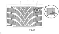
- the tyre has a configuration of V-shaped grooves characteristic of a unidirectional tyre.
- the angle of the grooves making up the V shape, with respect to the tyre width direction, changes from small to large from the shoulder region to the centre region of the tyre. Hence the angle is larger near the tyre equatorial plane.
- the dam 14 is positioned approximately in the middle in the groove longitudinal direction of the groove section in which it is located.
- the groove section extends from the tread end to the intersection with a groove (circumferential groove 40) running in the tyre circumferential direction.
- This groove section has a relatively small angle with respect to the tyre width direction. Therefore, snow slides particularly in this groove section during cornering.
- the contact patch 38 is also shown in Fig. 2 with a dotted line.
- the dam 14 is provided only in the shoulder regions of the tyre, and only in tyre width direction grooves. However, this is not essential, and the dam 14 may be provided elsewhere in addition or alternatively, possibly in grooves other than tyre width direction grooves.
- the cross-sectional view along line A-A' shows the inside of the dam 14.
- the hole 32 is shown, but the sipe 34 is not.
- D G denotes the depth of the groove 12, and D D the depth of the dam 14.
- the depth D D of the dam 14 is, in the present embodiment, about 25% of the depth D G of the groove 12. Accordingly, in the present embodiment, when viewed in the groove longitudinal direction, the dam 14 extends about a quarter of the way across the area of the groove 12 from the bottom wall 16. In the present embodiment, the dam 14 occupies about 2% of the volume of the groove section. As shown, the dam 14 forms a right-angled triangle in cross-section.
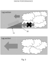
- Fig. 3 illustrates schematically the snow performance of the tyre of the preferred embodiment, in comparison to a tyre without a snow trapping device.
- Fig. 4 illustrates schematically the wet performance of the tyre of the preferred embodiment.
- Fig. 4 water flowing along the groove 12 from left to right encounters the dam 14 and in particular the inclined surface 24.
- the surface 24 directs the flow upwards and away from the bottom wall 16 of the groove 12.
- Some of the water then flows through the hole 32 parallel to the groove longitudinal direction.
- the majority of the water continues up the inclined surface 24 and over the top of the dam 14 and then down towards the bottom wall 16 of the groove 12.
- a recirculation region 36 is shown downstream of the snow trapping surface 22.
- the flows of water meet in this recirculation region 36, and the flow which has passed through the hole 32 reduces the size of the recirculation region in comparison to the case where there is no flow through the dam 14. This reduces flow losses and improves water drainage from the tyre.
- Fig. 5 shows the snow density on the tyre tread of a tyre without a snow trapping device
- Fig. 6 shows the snow density on the tyre tread of a tyre with a snow trapping device according to the embodiment of Fig. 1 .
- contour lines join points of equal snow density.
- the area inside the dashed boxes contains the dams 14, and these areas have a low density where the dams 14 are, but have areas of higher snow density around the dams 14 than the corresponding areas in Fig. 5 .
- the shape of the contour lines shows that the snow density is high in the circumferential groove 40 as well as in the adjacent tyre width direction groove.
- the results show an increase of about 22% in lateral force when the dams 14 are present in comparison to the case where they are not.
- the results also showed an increase in the amount of snow flowing into the circumferential direction grooves intersecting the groove section in which the dam 14 is located. This contributed to an improvement in grip in the snow.
- the flow into these circumferential grooves has the following mechanism. During cornering, snow in the contact patch is subject to a force with a component in the width direction of the tyre but also with a component in the circumferential direction. (During traction, the circumferential component is upwards in Fig. 2 , and left to right in Figs 5 and 6 ). The component in the circumferential direction causes the snow to flow towards the groove section in which the dam 14 is located. However, the snow trapped by the dam 14 causes the snow from the contact patch to be diverted into the circumferential groove 40. This increases the snow density in the circumferential groove 40 and the snow gripping effect.
- the simulations did not show any significant change in performance due to the presence of the dams 14.
- the simulations were carried out with the assumption that the flow was both inviscid and laminar, because of the technical limitations of the simulation equipment.
- the recirculation region downstream of the dam 14 will be mainly due to viscous and turbulence effects. Therefore, it is to be expected that, in reality, the wet performance will be significantly worse than the simulations show, and also that the presence of the passageway 30 will beneficial to counteract the recirculation.
- the dam 14 when viewed in the groove longitudinal direction, the dam 14 extends about a quarter of the way across the area of the groove 12 from the bottom wall 16. However, this is not essential. In addition, in the present embodiment, the dam 14 occupies about 2% of the volume of the groove section, but again this is not essential.
Landscapes
- Engineering & Computer Science (AREA)
- Mechanical Engineering (AREA)
- Tires In General (AREA)
Claims (14)
- Pneumatique comprenant :une bande de roulement (10) avec une rainure (12), la rainure (12) ayant dans son intérieur un dispositif de retenue de neige (14) fixé à une paroi de fond (16) de la rainure (12), le dispositif de retenue de neige (14) ayant une première surface (22) faisant face à un premier côté dans la direction longitudinale de rainure, la première surface (22) étant conçue pour retenir de la neige s'écoulant à partir du premier côté dans la direction longitudinale de rainure, et le dispositif (14) ayant une seconde surface (24) faisant face à un second côté dans la direction longitudinale de rainure qui est opposé au premier côté, la seconde surface (24) étant inclinée de manière à diriger de l'eau s'écoulant à partir du second côté à l'écart de la paroi de fond (16) de la rainure (12),dans lequel des parties (26, 28) du dispositif (14) se chevauchent le long de la direction longitudinale de rainure de manière à former un passage (30) pour l'eau à travers le dispositif (14) dans la direction longitudinale de rainure,dans lequel, dans une vue en plan de la bande de roulement (10), l'ensemble du dispositif (14) est positionné entre les parois latérales (18, 20) de la rainure (12),dans lequel, lorsque le dispositif de retenue de neige (14) traverse l'aire de contact du pneumatique, les parties (26, 28) qui se chevauchent sont jointes ou en contact l'une avec l'autre de sorte que le passage (30) est formé entre un point de jonction ou de contact et la paroi de fond (16) de la rainure (12),caractérisé en ce quele passage (30) comprend une lamelle (34) et un trou (32) dans le dispositif (14), la lamelle (34) étant formée à l'extérieur du trou (32) dans une direction radiale de pneumatique et adjacente au trou (32), etdans lequel la profondeur du dispositif de retenue de neige (14) est au maximum égale à 50 % de la profondeur de la rainure (12), dans lequel la profondeur est mesurée à partir de la paroi de fond (16) de la rainure (12).
- Pneumatique selon la revendication 1, dans lequel la lamelle (34) est fournie au niveau du point de contact qui permet aux parties (26, 28) d'entrer en contact l'une avec l'autre.
- Pneumatique selon la revendication 1 ou 2, dans lequel les parties du dispositif (14) qui se chevauchent dans la direction longitudinale de rainure sont formées d'un seul tenant.
- Pneumatique selon l'une quelconque revendication précédente, dans lequel le trou (32) est formé dans la seconde surface (24).
- Pneumatique selon l'une quelconque revendication précédente, dans lequel le trou (32) est formé dans la première surface (22).
- Pneumatique selon l'une quelconque revendication précédente, dans lequel, vu dans la direction longitudinale de rainure, le dispositif de retenue de neige (14) s'étend au maximum sur la moitié de la surface de la rainure (12) à partir de la paroi de fond (16) de la rainure (12).
- Pneumatique selon l'une quelconque revendication précédente, dans lequel la seconde surface (24) dirige l'eau s'écoulant à partir du second côté vers l'extérieur dans une direction radiale de pneumatique.
- Pneumatique selon l'une quelconque revendication précédente, dans lequel la première surface (22) s'étend dans une direction qui est sensiblement parallèle à la direction de largeur de rainure.
- Pneumatique selon l'une quelconque revendication précédente, dans lequel la première surface (22) est plane.
- Pneumatique selon l'une quelconque revendication précédente, dans lequel la seconde surface (24) est plane.
- Pneumatique selon l'une quelconque revendication précédente, dans lequel la rainure (12) est une rainure (12) de direction de largeur.
- Pneumatique selon l'une quelconque revendication précédente, dans lequel le premier côté est l'extérieur dans la direction de largeur de pneumatique.
- Pneumatique selon l'une quelconque revendication précédente, dans lequel le dispositif de retenue de neige (14) est situé à au moins 25 % de la longueur d'une section de rainure dans laquelle il est situé à partir d'une extrémité de la section de rainure.
- Pneumatique selon la revendication 13, dans lequel le dispositif de retenue de neige (14) est situé approximativement au milieu dans la direction longitudinale de rainure de la section de rainure dans laquelle il est situé.
Priority Applications (5)
| Application Number | Priority Date | Filing Date | Title |
|---|---|---|---|
| EP20020140.8A EP3888946B1 (fr) | 2020-03-30 | 2020-03-30 | Pneumatique |
| CN202180034125.4A CN115605356B (zh) | 2020-03-30 | 2021-03-26 | 轮胎 |
| PCT/EP2021/058019 WO2021198105A1 (fr) | 2020-03-30 | 2021-03-26 | Pneu |
| CA3176474A CA3176474A1 (fr) | 2020-03-30 | 2021-03-26 | Pneu |
| US17/914,198 US12589616B2 (en) | 2020-03-30 | 2021-03-26 | Tire |
Applications Claiming Priority (1)
| Application Number | Priority Date | Filing Date | Title |
|---|---|---|---|
| EP20020140.8A EP3888946B1 (fr) | 2020-03-30 | 2020-03-30 | Pneumatique |
Publications (2)
| Publication Number | Publication Date |
|---|---|
| EP3888946A1 EP3888946A1 (fr) | 2021-10-06 |
| EP3888946B1 true EP3888946B1 (fr) | 2024-11-06 |
Family
ID=70108015
Family Applications (1)
| Application Number | Title | Priority Date | Filing Date |
|---|---|---|---|
| EP20020140.8A Active EP3888946B1 (fr) | 2020-03-30 | 2020-03-30 | Pneumatique |
Country Status (5)
| Country | Link |
|---|---|
| US (1) | US12589616B2 (fr) |
| EP (1) | EP3888946B1 (fr) |
| CN (1) | CN115605356B (fr) |
| CA (1) | CA3176474A1 (fr) |
| WO (1) | WO2021198105A1 (fr) |
Families Citing this family (2)
| Publication number | Priority date | Publication date | Assignee | Title |
|---|---|---|---|---|
| CN118849671A (zh) * | 2023-04-28 | 2024-10-29 | 北京小米移动软件有限公司 | 驱动轮及清洁设备 |
| JP7659204B2 (ja) * | 2023-09-07 | 2025-04-09 | 横浜ゴム株式会社 | タイヤ |
Family Cites Families (25)
| Publication number | Priority date | Publication date | Assignee | Title |
|---|---|---|---|---|
| DE2333589A1 (de) * | 1973-07-02 | 1975-02-06 | Hans Dipl Ing Lange | Verfahren und vorrichtungen zum regelbaren widerstand zwischen dem strassenbelag und dem eleastischen andruck aus einem beweglichen dorn oder einem mit harten duennen metallstuecken aufgefuellten gummiriemen, der im autoreifen eingebettet ist |
| JPH061119A (ja) * | 1992-06-22 | 1994-01-11 | Yokohama Rubber Co Ltd:The | 氷雪路用空気入りタイヤ |
| JP3204741B2 (ja) * | 1992-07-06 | 2001-09-04 | オーツタイヤ株式会社 | タイヤのトレッド構造 |
| JP3229405B2 (ja) * | 1992-12-24 | 2001-11-19 | 横浜ゴム株式会社 | 空気入りタイヤ |
| JPH07172114A (ja) * | 1993-12-21 | 1995-07-11 | Bridgestone Corp | 重荷重用空気入りタイヤ |
| JP2966760B2 (ja) | 1995-04-18 | 1999-10-25 | 住友ゴム工業株式会社 | 重荷重用タイヤ |
| US5785782A (en) * | 1995-05-02 | 1998-07-28 | Tsuzuki Electric Corporation | Slip-preventing vehicle tire |
| JP2934405B2 (ja) * | 1996-01-30 | 1999-08-16 | 住友ゴム工業株式会社 | 空気入りタイヤ |
| JP4285823B2 (ja) * | 1999-02-05 | 2009-06-24 | 住友ゴム工業株式会社 | 空気入りタイヤ |
| JP2001187517A (ja) * | 1999-12-28 | 2001-07-10 | Bridgestone Corp | 空気入りタイヤ |
| KR20040104118A (ko) | 2003-06-03 | 2004-12-10 | 박종우 | 안경다리의 제조용 커팅장치 |
| KR20060065297A (ko) * | 2004-12-10 | 2006-06-14 | 한국타이어 주식회사 | 스노우 타이어 |
| JP5270407B2 (ja) | 2009-03-09 | 2013-08-21 | 東洋ゴム工業株式会社 | 空気入りタイヤ |
| JP4829994B2 (ja) * | 2009-04-06 | 2011-12-07 | 住友ゴム工業株式会社 | 空気入りタイヤ |
| JP2010254033A (ja) * | 2009-04-22 | 2010-11-11 | Bridgestone Corp | 空気入りタイヤ |
| KR20110064552A (ko) * | 2009-12-08 | 2011-06-15 | 한국타이어 주식회사 | 타이어의 수막현상 성능을 향상시킨 트레드 홈 |
| FR2954221B1 (fr) * | 2009-12-17 | 2012-03-16 | Michelin Soc Tech | Pneu a performance de roulage amelioree |
| JP5291739B2 (ja) * | 2011-03-02 | 2013-09-18 | 住友ゴム工業株式会社 | 空気入りタイヤ |
| DE102011051224B4 (de) * | 2011-06-21 | 2020-12-31 | Continental Reifen Deutschland Gmbh | Fahrzeugluftreifen |
| JP5503622B2 (ja) * | 2011-11-08 | 2014-05-28 | 住友ゴム工業株式会社 | 空気入りタイヤ |
| FR3012768B1 (fr) * | 2013-11-05 | 2016-12-23 | Michelin & Cie | Bande de roulement comportant un bloc presentant une pluralite d'incisions |
| CN106457921B (zh) * | 2014-06-30 | 2019-04-02 | 米其林集团总公司 | 轮胎胎面和轮胎的可变宽度胎纹沟槽 |
| FR3026347B1 (fr) * | 2014-09-30 | 2018-03-23 | Compagnie Generale Des Etablissements Michelin | Pneumatique comportant une bande de roulement comprenant un element en protuberance dans une rainure transversale |
| NO2795041T3 (fr) | 2015-06-01 | 2018-01-27 | ||
| KR102253921B1 (ko) * | 2019-04-15 | 2021-05-20 | 한국타이어앤테크놀로지 주식회사 | 공기입 타이어 |
-
2020
- 2020-03-30 EP EP20020140.8A patent/EP3888946B1/fr active Active
-
2021
- 2021-03-26 CA CA3176474A patent/CA3176474A1/fr active Pending
- 2021-03-26 CN CN202180034125.4A patent/CN115605356B/zh active Active
- 2021-03-26 US US17/914,198 patent/US12589616B2/en active Active
- 2021-03-26 WO PCT/EP2021/058019 patent/WO2021198105A1/fr not_active Ceased
Also Published As
| Publication number | Publication date |
|---|---|
| WO2021198105A1 (fr) | 2021-10-07 |
| CA3176474A1 (fr) | 2021-10-07 |
| CN115605356B (zh) | 2025-11-28 |
| EP3888946A1 (fr) | 2021-10-06 |
| US20230115477A1 (en) | 2023-04-13 |
| CN115605356A (zh) | 2023-01-13 |
| US12589616B2 (en) | 2026-03-31 |
Similar Documents
| Publication | Publication Date | Title |
|---|---|---|
| CN102548777B (zh) | 具有改善的刚性的轮胎胎面 | |
| US12589616B2 (en) | Tire | |
| EP1541383A2 (fr) | Profil de bande de roulement de pneumatique | |
| EP2570272A1 (fr) | Chape de pneu | |
| CN104487265B (zh) | 重负载用充气轮胎 | |
| CN104010834B (zh) | 充气轮胎 | |
| JP2008221955A (ja) | 空気入りタイヤ | |
| JPS62241712A (ja) | スタッドレス空気入りタイヤ | |
| JP5865070B2 (ja) | 空気入りタイヤ | |
| CN108602394A (zh) | 充气轮胎 | |
| JP5832887B2 (ja) | 空気入りタイヤ | |
| US11993103B2 (en) | Pneumatic tire | |
| JPH04345504A (ja) | 空気入りタイヤ | |
| JP5865071B2 (ja) | 空気入りタイヤ | |
| JP6391483B2 (ja) | 空気入りタイヤ | |
| JP3502166B2 (ja) | 空気入りラジアルタイヤ | |
| EA046460B1 (ru) | Шина | |
| EA044896B1 (ru) | Шина | |
| JP2004306906A (ja) | 空気入りタイヤ | |
| JP6735131B2 (ja) | タイヤ | |
| CN112918194A (zh) | 一种充气轮胎和车辆 | |
| US12251969B2 (en) | Tire tread for a heavy goods vehicle tire having improved incisions | |
| CN116568530A (zh) | 用于重型车辆的具有改进的抗攻击性的轮胎胎面 | |
| JP2003191714A (ja) | 排水性能にすぐれた空気入りタイヤ | |
| JP6161947B2 (ja) | タイヤ |
Legal Events
| Date | Code | Title | Description |
|---|---|---|---|
| PUAI | Public reference made under article 153(3) epc to a published international application that has entered the european phase |
Free format text: ORIGINAL CODE: 0009012 |
|
| STAA | Information on the status of an ep patent application or granted ep patent |
Free format text: STATUS: THE APPLICATION HAS BEEN PUBLISHED |
|
| AK | Designated contracting states |
Kind code of ref document: A1 Designated state(s): AL AT BE BG CH CY CZ DE DK EE ES FI FR GB GR HR HU IE IS IT LI LT LU LV MC MK MT NL NO PL PT RO RS SE SI SK SM TR |
|
| STAA | Information on the status of an ep patent application or granted ep patent |
Free format text: STATUS: REQUEST FOR EXAMINATION WAS MADE |
|
| 17P | Request for examination filed |
Effective date: 20220406 |
|
| RBV | Designated contracting states (corrected) |
Designated state(s): AL AT BE BG CH CY CZ DE DK EE ES FI FR GB GR HR HU IE IS IT LI LT LU LV MC MK MT NL NO PL PT RO RS SE SI SK SM TR |
|
| STAA | Information on the status of an ep patent application or granted ep patent |
Free format text: STATUS: EXAMINATION IS IN PROGRESS |
|
| 17Q | First examination report despatched |
Effective date: 20220928 |
|
| RAP3 | Party data changed (applicant data changed or rights of an application transferred) |
Owner name: BRIDGESTONE EUROPE NV/SA |
|
| GRAP | Despatch of communication of intention to grant a patent |
Free format text: ORIGINAL CODE: EPIDOSNIGR1 |
|
| STAA | Information on the status of an ep patent application or granted ep patent |
Free format text: STATUS: GRANT OF PATENT IS INTENDED |
|
| INTG | Intention to grant announced |
Effective date: 20240528 |
|
| GRAS | Grant fee paid |
Free format text: ORIGINAL CODE: EPIDOSNIGR3 |
|
| GRAA | (expected) grant |
Free format text: ORIGINAL CODE: 0009210 |
|
| STAA | Information on the status of an ep patent application or granted ep patent |
Free format text: STATUS: THE PATENT HAS BEEN GRANTED |
|
| AK | Designated contracting states |
Kind code of ref document: B1 Designated state(s): AL AT BE BG CH CY CZ DE DK EE ES FI FR GB GR HR HU IE IS IT LI LT LU LV MC MK MT NL NO PL PT RO RS SE SI SK SM TR |
|
| REG | Reference to a national code |
Ref country code: GB Ref legal event code: FG4D |
|
| REG | Reference to a national code |
Ref country code: CH Ref legal event code: EP |
|
| REG | Reference to a national code |
Ref country code: DE Ref legal event code: R096 Ref document number: 602020040637 Country of ref document: DE |
|
| REG | Reference to a national code |
Ref country code: IE Ref legal event code: FG4D |
|
| REG | Reference to a national code |
Ref country code: LT Ref legal event code: MG9D |
|
| REG | Reference to a national code |
Ref country code: NL Ref legal event code: MP Effective date: 20241106 |
|
| P01 | Opt-out of the competence of the unified patent court (upc) registered |
Free format text: CASE NUMBER: APP_8752/2025 Effective date: 20250220 |
|
| PG25 | Lapsed in a contracting state [announced via postgrant information from national office to epo] |
Ref country code: HR Free format text: LAPSE BECAUSE OF FAILURE TO SUBMIT A TRANSLATION OF THE DESCRIPTION OR TO PAY THE FEE WITHIN THE PRESCRIBED TIME-LIMIT Effective date: 20241106 Ref country code: IS Free format text: LAPSE BECAUSE OF FAILURE TO SUBMIT A TRANSLATION OF THE DESCRIPTION OR TO PAY THE FEE WITHIN THE PRESCRIBED TIME-LIMIT Effective date: 20250306 Ref country code: PT Free format text: LAPSE BECAUSE OF FAILURE TO SUBMIT A TRANSLATION OF THE DESCRIPTION OR TO PAY THE FEE WITHIN THE PRESCRIBED TIME-LIMIT Effective date: 20250306 |
|
| PG25 | Lapsed in a contracting state [announced via postgrant information from national office to epo] |
Ref country code: NL Free format text: LAPSE BECAUSE OF FAILURE TO SUBMIT A TRANSLATION OF THE DESCRIPTION OR TO PAY THE FEE WITHIN THE PRESCRIBED TIME-LIMIT Effective date: 20241106 Ref country code: FI Free format text: LAPSE BECAUSE OF FAILURE TO SUBMIT A TRANSLATION OF THE DESCRIPTION OR TO PAY THE FEE WITHIN THE PRESCRIBED TIME-LIMIT Effective date: 20241106 |
|
| REG | Reference to a national code |
Ref country code: AT Ref legal event code: MK05 Ref document number: 1739002 Country of ref document: AT Kind code of ref document: T Effective date: 20241106 |
|
| PG25 | Lapsed in a contracting state [announced via postgrant information from national office to epo] |
Ref country code: BG Free format text: LAPSE BECAUSE OF FAILURE TO SUBMIT A TRANSLATION OF THE DESCRIPTION OR TO PAY THE FEE WITHIN THE PRESCRIBED TIME-LIMIT Effective date: 20241106 |
|
| PG25 | Lapsed in a contracting state [announced via postgrant information from national office to epo] |
Ref country code: ES Free format text: LAPSE BECAUSE OF FAILURE TO SUBMIT A TRANSLATION OF THE DESCRIPTION OR TO PAY THE FEE WITHIN THE PRESCRIBED TIME-LIMIT Effective date: 20241106 |
|
| PG25 | Lapsed in a contracting state [announced via postgrant information from national office to epo] |
Ref country code: NO Free format text: LAPSE BECAUSE OF FAILURE TO SUBMIT A TRANSLATION OF THE DESCRIPTION OR TO PAY THE FEE WITHIN THE PRESCRIBED TIME-LIMIT Effective date: 20250206 |
|
| PG25 | Lapsed in a contracting state [announced via postgrant information from national office to epo] |
Ref country code: GR Free format text: LAPSE BECAUSE OF FAILURE TO SUBMIT A TRANSLATION OF THE DESCRIPTION OR TO PAY THE FEE WITHIN THE PRESCRIBED TIME-LIMIT Effective date: 20250207 Ref country code: LV Free format text: LAPSE BECAUSE OF FAILURE TO SUBMIT A TRANSLATION OF THE DESCRIPTION OR TO PAY THE FEE WITHIN THE PRESCRIBED TIME-LIMIT Effective date: 20241106 Ref country code: AT Free format text: LAPSE BECAUSE OF FAILURE TO SUBMIT A TRANSLATION OF THE DESCRIPTION OR TO PAY THE FEE WITHIN THE PRESCRIBED TIME-LIMIT Effective date: 20241106 |
|
| PG25 | Lapsed in a contracting state [announced via postgrant information from national office to epo] |
Ref country code: PL Free format text: LAPSE BECAUSE OF FAILURE TO SUBMIT A TRANSLATION OF THE DESCRIPTION OR TO PAY THE FEE WITHIN THE PRESCRIBED TIME-LIMIT Effective date: 20241106 |
|
| PG25 | Lapsed in a contracting state [announced via postgrant information from national office to epo] |
Ref country code: RS Free format text: LAPSE BECAUSE OF FAILURE TO SUBMIT A TRANSLATION OF THE DESCRIPTION OR TO PAY THE FEE WITHIN THE PRESCRIBED TIME-LIMIT Effective date: 20250206 |
|
| PG25 | Lapsed in a contracting state [announced via postgrant information from national office to epo] |
Ref country code: SM Free format text: LAPSE BECAUSE OF FAILURE TO SUBMIT A TRANSLATION OF THE DESCRIPTION OR TO PAY THE FEE WITHIN THE PRESCRIBED TIME-LIMIT Effective date: 20241106 |
|
| PG25 | Lapsed in a contracting state [announced via postgrant information from national office to epo] |
Ref country code: DK Free format text: LAPSE BECAUSE OF FAILURE TO SUBMIT A TRANSLATION OF THE DESCRIPTION OR TO PAY THE FEE WITHIN THE PRESCRIBED TIME-LIMIT Effective date: 20241106 |
|
| PG25 | Lapsed in a contracting state [announced via postgrant information from national office to epo] |
Ref country code: EE Free format text: LAPSE BECAUSE OF FAILURE TO SUBMIT A TRANSLATION OF THE DESCRIPTION OR TO PAY THE FEE WITHIN THE PRESCRIBED TIME-LIMIT Effective date: 20241106 |
|
| PG25 | Lapsed in a contracting state [announced via postgrant information from national office to epo] |
Ref country code: RO Free format text: LAPSE BECAUSE OF FAILURE TO SUBMIT A TRANSLATION OF THE DESCRIPTION OR TO PAY THE FEE WITHIN THE PRESCRIBED TIME-LIMIT Effective date: 20241106 |
|
| PG25 | Lapsed in a contracting state [announced via postgrant information from national office to epo] |
Ref country code: SK Free format text: LAPSE BECAUSE OF FAILURE TO SUBMIT A TRANSLATION OF THE DESCRIPTION OR TO PAY THE FEE WITHIN THE PRESCRIBED TIME-LIMIT Effective date: 20241106 |
|
| PG25 | Lapsed in a contracting state [announced via postgrant information from national office to epo] |
Ref country code: CZ Free format text: LAPSE BECAUSE OF FAILURE TO SUBMIT A TRANSLATION OF THE DESCRIPTION OR TO PAY THE FEE WITHIN THE PRESCRIBED TIME-LIMIT Effective date: 20241106 |
|
| PG25 | Lapsed in a contracting state [announced via postgrant information from national office to epo] |
Ref country code: IT Free format text: LAPSE BECAUSE OF FAILURE TO SUBMIT A TRANSLATION OF THE DESCRIPTION OR TO PAY THE FEE WITHIN THE PRESCRIBED TIME-LIMIT Effective date: 20241106 |
|
| REG | Reference to a national code |
Ref country code: DE Ref legal event code: R097 Ref document number: 602020040637 Country of ref document: DE |
|
| PG25 | Lapsed in a contracting state [announced via postgrant information from national office to epo] |
Ref country code: SE Free format text: LAPSE BECAUSE OF FAILURE TO SUBMIT A TRANSLATION OF THE DESCRIPTION OR TO PAY THE FEE WITHIN THE PRESCRIBED TIME-LIMIT Effective date: 20241106 |
|
| PLBE | No opposition filed within time limit |
Free format text: ORIGINAL CODE: 0009261 |
|
| STAA | Information on the status of an ep patent application or granted ep patent |
Free format text: STATUS: NO OPPOSITION FILED WITHIN TIME LIMIT |
|
| PG25 | Lapsed in a contracting state [announced via postgrant information from national office to epo] |
Ref country code: MC Free format text: LAPSE BECAUSE OF FAILURE TO SUBMIT A TRANSLATION OF THE DESCRIPTION OR TO PAY THE FEE WITHIN THE PRESCRIBED TIME-LIMIT Effective date: 20241106 |
|
| 26N | No opposition filed |
Effective date: 20250807 |
|
| REG | Reference to a national code |
Ref country code: CH Ref legal event code: H13 Free format text: ST27 STATUS EVENT CODE: U-0-0-H10-H13 (AS PROVIDED BY THE NATIONAL OFFICE) Effective date: 20251023 |
|
| PG25 | Lapsed in a contracting state [announced via postgrant information from national office to epo] |
Ref country code: LU Free format text: LAPSE BECAUSE OF NON-PAYMENT OF DUE FEES Effective date: 20250330 |
|
| GBPC | Gb: european patent ceased through non-payment of renewal fee |
Effective date: 20250330 |
|
| REG | Reference to a national code |
Ref country code: BE Ref legal event code: MM Effective date: 20250331 |
|
| PG25 | Lapsed in a contracting state [announced via postgrant information from national office to epo] |
Ref country code: GB Free format text: LAPSE BECAUSE OF NON-PAYMENT OF DUE FEES Effective date: 20250330 |
|
| PG25 | Lapsed in a contracting state [announced via postgrant information from national office to epo] |
Ref country code: BE Free format text: LAPSE BECAUSE OF NON-PAYMENT OF DUE FEES Effective date: 20250331 |
|
| PG25 | Lapsed in a contracting state [announced via postgrant information from national office to epo] |
Ref country code: CH Free format text: LAPSE BECAUSE OF NON-PAYMENT OF DUE FEES Effective date: 20250331 |
|
| PG25 | Lapsed in a contracting state [announced via postgrant information from national office to epo] |
Ref country code: IE Free format text: LAPSE BECAUSE OF NON-PAYMENT OF DUE FEES Effective date: 20250330 |
|
| PGFP | Annual fee paid to national office [announced via postgrant information from national office to epo] |
Ref country code: DE Payment date: 20260219 Year of fee payment: 7 |
|
| PGFP | Annual fee paid to national office [announced via postgrant information from national office to epo] |
Ref country code: FR Payment date: 20260220 Year of fee payment: 7 |