EP3888953B1 - Pneu à chambres multiples - Google Patents
Pneu à chambres multiples Download PDFInfo
- Publication number
- EP3888953B1 EP3888953B1 EP19890147.2A EP19890147A EP3888953B1 EP 3888953 B1 EP3888953 B1 EP 3888953B1 EP 19890147 A EP19890147 A EP 19890147A EP 3888953 B1 EP3888953 B1 EP 3888953B1
- Authority
- EP
- European Patent Office
- Prior art keywords
- tire
- air chamber
- partition walls
- coupling portion
- wall surface
- Prior art date
- Legal status (The legal status is an assumption and is not a legal conclusion. Google has not performed a legal analysis and makes no representation as to the accuracy of the status listed.)
- Active
Links
Images

Classifications
-
- B—PERFORMING OPERATIONS; TRANSPORTING
- B60—VEHICLES IN GENERAL
- B60C—VEHICLE TYRES; TYRE INFLATION; TYRE CHANGING; CONNECTING VALVES TO INFLATABLE ELASTIC BODIES IN GENERAL; DEVICES OR ARRANGEMENTS RELATED TO TYRES
- B60C5/00—Inflatable pneumatic tyres or inner tubes
- B60C5/20—Inflatable pneumatic tyres or inner tubes having multiple separate inflatable chambers
- B60C5/22—Inflatable pneumatic tyres or inner tubes having multiple separate inflatable chambers the chambers being annular
-
- B—PERFORMING OPERATIONS; TRANSPORTING
- B60—VEHICLES IN GENERAL
- B60C—VEHICLE TYRES; TYRE INFLATION; TYRE CHANGING; CONNECTING VALVES TO INFLATABLE ELASTIC BODIES IN GENERAL; DEVICES OR ARRANGEMENTS RELATED TO TYRES
- B60C17/00—Tyres characterised by means enabling restricted operation in damaged or deflated condition; Accessories therefor
- B60C17/01—Tyres characterised by means enabling restricted operation in damaged or deflated condition; Accessories therefor utilising additional inflatable supports which become load-supporting in emergency
-
- B—PERFORMING OPERATIONS; TRANSPORTING
- B60—VEHICLES IN GENERAL
- B60C—VEHICLE TYRES; TYRE INFLATION; TYRE CHANGING; CONNECTING VALVES TO INFLATABLE ELASTIC BODIES IN GENERAL; DEVICES OR ARRANGEMENTS RELATED TO TYRES
- B60C29/00—Arrangements of tyre-inflating valves to tyres or rims; Accessories for tyre-inflating valves, not otherwise provided for
- B60C29/007—Arrangements of tyre-inflating valves to tyres or rims; Accessories for tyre-inflating valves, not otherwise provided for for tyres with segmental sections or for multi-chamber tyres
-
- Y—GENERAL TAGGING OF NEW TECHNOLOGICAL DEVELOPMENTS; GENERAL TAGGING OF CROSS-SECTIONAL TECHNOLOGIES SPANNING OVER SEVERAL SECTIONS OF THE IPC; TECHNICAL SUBJECTS COVERED BY FORMER USPC CROSS-REFERENCE ART COLLECTIONS [XRACs] AND DIGESTS
- Y10—TECHNICAL SUBJECTS COVERED BY FORMER USPC
- Y10T—TECHNICAL SUBJECTS COVERED BY FORMER US CLASSIFICATION
- Y10T152/00—Resilient tires and wheels
- Y10T152/10—Tires, resilient
- Y10T152/10495—Pneumatic tire or inner tube
- Y10T152/10522—Multiple chamber
- Y10T152/10576—Annular chambers
- Y10T152/10585—Annular chambers with simultaneous inflating means
-
- Y—GENERAL TAGGING OF NEW TECHNOLOGICAL DEVELOPMENTS; GENERAL TAGGING OF CROSS-SECTIONAL TECHNOLOGIES SPANNING OVER SEVERAL SECTIONS OF THE IPC; TECHNICAL SUBJECTS COVERED BY FORMER USPC CROSS-REFERENCE ART COLLECTIONS [XRACs] AND DIGESTS
- Y10—TECHNICAL SUBJECTS COVERED BY FORMER USPC
- Y10T—TECHNICAL SUBJECTS COVERED BY FORMER US CLASSIFICATION
- Y10T152/00—Resilient tires and wheels
- Y10T152/10—Tires, resilient
- Y10T152/10495—Pneumatic tire or inner tube
- Y10T152/10522—Multiple chamber
- Y10T152/10576—Annular chambers
- Y10T152/10612—Annular chambers with simultaneous inflating means
Definitions
- the present invention relates to a multi air chamber tire.
- PTL 1 discloses a run flat tire where side reinforcing rubber is disposed on each sidewall portion of a tire. Further reference may be made to multi air chamber tire structures disclosed in PTL 2, PTL 3 and PTL 4.
- the present invention has been made under such circumstances, and it is an object of the present invention to provide a multi air chamber tire which allows safe travel over a certain distance when tire failure occurs while suppressing deterioration of ride comfort.
- a multi air chamber tire according to the present invention is defined in claim 1 and includes: a tread portion; a pair of bead portions; a pair of sidewall portions extending between the tread portion and the pair of bead portions; and partition walls respectively provided to half portions of a tire which are defined with respect to a tire equator plane, the partition walls partitioning an inner cavity of the tire to form a plurality of air chambers disposed adjacent to each other, wherein each of the partition walls includes a first coupling portion coupled with a tire inner wall surface, and a second coupling portion coupled with the tire inner wall surface at a position outward of the first coupling portion in a tire radial direction, in a state where the tire is filled with fluid, a first air chamber is formed in a space located at a position inward of the partition walls in a tire width direction, and a second air chamber is formed in a space located between a partition wall of the partition walls and the tire inner wall surface of a sidewall portion of the pair of sidewall portions, the second coupling
- ground contact width of the tire a width in the tire width direction of a contact patch which comes into contact with a road surface in a state where the tire is mounted on the applicable rim, the tire is filled with the prescribed internal pressure, and the maximum load is applied to the tire.
- ground contact width of the tire an edge portion in the tire width direction of the ground contact width of the tire is referred to as "ground contact edge”.
- appcable rim indicates an approved rim (Measuring Rim in STANDARDS MANUAL of ETRTO, and Design Rim in YEAR BOOK of TRA) having an applicable size which is described or which will be described in the future in the industrial standards applicable to regions where pneumatic tires are produced and used, including JATMA YEAR BOOK by JATMA (the Japan Automobile Tyre Manufacturers Association) in Japan, STANDARDS MANUAL by ETRTO (The European Tyre and Rim Technical Organisation) in Europe, and YEAR BOOK by TRA (The Tire and Rim Association, Inc.) in the United States of America.
- JATMA YEAR BOOK by JATMA the Japan Automobile Tyre Manufacturers Association
- ETRTO European Tyre and Rim Technical Organisation
- TRA The Tire and Rim Association, Inc.
- appcable rim indicates a rim having a width which corresponds to the bead width of a pneumatic tire.
- the term “applicable rim” also includes a size which may be included in the above-mentioned industrial standard in the future in addition to the current size.
- An example of "size which will be described in the future” includes a size described as “FUTURE DEVELOPMENTS” in ETRTO 2013.
- “prescribed internal pressure” indicates an air pressure (maximum air pressure) which corresponds to the maximum load capability of a single wheel having an applicable size and a ply rating, and which is described in the industrial standard, such as the above-mentioned JATMA YEAR BOOK.
- “prescribed internal pressure” indicates an air pressure (maximum air pressure) which corresponds to the maximum load capability specified for each vehicle on which the tire is mounted.
- “maximum load” indicates a load which corresponds to the maximum load capability of a tire having an applicable size described in the above-mentioned industrial standard.
- “maximum load” indicates a load which corresponds to the maximum load capability specified for each vehicle on which the tire is mounted.
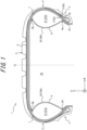
- FIG. 1 is a tire width direction cross-sectional view of the multi air chamber tire 1 not forming part of the present invention (hereinafter also referred to as "tire 1") taken along the tire width direction.
- the tire 1 includes a pair of partition walls 30a and 30b which partitions the inner cavity of the tire into a plurality of spaces, the partition walls 30a and 30b being respectively provided to half portions of the tire which are defined with respect to a tire equator plane CL.
- the partition walls 30a and 30b may be film members coated with rubber, for example.
- the partition walls 30a and 30b are not limited to the above, and may be any partition walls which can prevent leakage of gas, such as air.
- a first air chamber 20 is formed at a position inward of the partition walls 30a and 30b in the tire width direction
- second air chambers 21a and 21b are respectively formed at positions outward of the partition walls 30a, 30b in the tire width direction.
- second air chamber 21 when the second air chambers 21a and 21b are not particularly distinguished from each other, the second air chambers 21a and 21b are collectively simply referred to as "second air chamber 21".
- partition walls 30a and 30b are not particularly distinguished from each other, the partition walls 30a and 30b are collectively simply referred to as "partition wall 30".
- the tire width direction indicates a direction parallel to the rotation axis of the tire 1.
- the tire width direction is indicated by an arrow W.
- the tire radial direction indicates a direction orthogonal to the rotation axis of the tire 1.
- the tire radial direction is indicated by an arrow R.
- the description will be made assuming that the tire 1 has a symmetrical configuration with respect to the tire equator plane CL.
- the configuration of the tire 1 is not limited to the above.
- the tire 1 may have an asymmetrical configuration with respect to the tire equator plane CL.
- a direction toward the rotation axis of the tire 1 in the tire radial direction is referred to as “inward in the tire radial direction”
- a direction away from the rotation axis of the tire 1 in the tire radial direction is referred to as “outward in the tire radial direction”.
- a direction toward the tire equator plane CL in the tire width direction is referred to as “inward in the tire width direction”
- a direction away from the tire equator plane CL in the tire width direction is referred to as "outward in the tire width direction”.
- the tire 1 includes a pair of bead portions 2, a pair of sidewall portions 3, and a tread portion 4.
- Each sidewall portion 3 extends between the tread portion 4 and the bead portion 2.
- the sidewall portion 3 is located at a position outward of the bead portion 2 in the tire radial direction.
- Each of the pair of bead portions 2 includes a bead core 2a and a bead filler 2b.
- the bead core 2a includes a plurality of bead wires coated with rubber around their peripheries.
- Each bead wire is formed of a steel cord.
- the steel cord may be formed of a steel monofilament or stranded wire, for example.
- the bead filler 2b is made of rubber or the like, and is located at a position outward of the bead core 2a in the tire radial direction. In this tire 1, the thickness of the bead filler 2b reduces toward the outward tire radial direction.
- the tire 1 may have a structure which includes no bead filler 2b.
- Each bead portion 2 is configured to be brought into contact with a rim at a position inward in the tire radial direction and outward in the tire width direction when the tire 1 is mounted on the rim.
- the tire 1 includes a carcass 5.
- the carcass 5 extends in a toroidal shape between the pair of bead cores 2a, thus forming the skeleton of the tire. End portions of the carcass 5 engage with the bead cores 2a.
- the carcass 5 includes a carcass main body portion 5a and carcass fold-back portions 5b.
- the carcass main body portion 5a is disposed between the bead cores 2a.
- Each carcass fold-back portion 5b is provided on the periphery of the bead core 2a, and is obtained by folding back the carcass 5 to extend from a position inward in the tire width direction toward a position outward in the tire width direction.
- a length of the carcass fold-back portion 5b from the position inward in the tire width direction toward the position outward in the tire width direction may be set to a desired length.
- the carcass 5 may have a structure which includes no carcass fold-back portion 5b, or may have a structure where each carcass fold-back portion 5b is wound around the bead core 2a.
- the carcass 5 may be formed of one or more carcass layers.
- the carcass 5 may be formed of two carcass layers arranged in a laminated manner in the tire radial direction in the tire equator plane CL.
- a carcass cord which forms the carcass layer of the carcass 5 is made of polyester, for example.
- the configuration is not limited to the above.
- the carcass cord may be made of an organic fiber, such as nylon, rayon, or aramid, and metal, such as steel.
- the carcass 5 has a radial structure.
- the carcass 5 is not limited to the radial structure, and may have a bias structure.
- a belt 6 and a tread rubber which reinforce the tread portion 4 are provided at positions outward of the carcass 5 in the tire radial direction.
- the belt 6 may be formed of a plurality of belt layers laminated in the tire radial direction, for example.
- a belt cord which forms the belt layer of the belt 6 is made of polyester, for example.
- the belt cord is not limited to polyester, and may be made of an organic fiber, such as nylon, rayon, or aramid, and metal, such as steel, for example.
- the tire 1 includes an inner liner 7.
- the inner liner 7 is disposed such that the inner liner 7 covers the inner wall surface of the tire 1.
- the inner liner 7 may be formed of a plurality of inner liner layers laminated in the tire radial direction in the tire equator plane CL.
- the inner liner 7 is made of butyl-based rubber having low air permeability, for example.
- the butyl-based rubber includes butyl rubber, and halogenated butyl rubber, which is a derivative of butyl rubber, for example.
- the inner liner 7 is not limited to butyl-based rubber, and may be made of other rubber composition, a resin, or elastomer.
- the tire 1 includes a reinforcement layer 8.
- the reinforcement layer 8 is disposed such that the reinforcement layer 8 covers the inner wall surface of the tire 1 at a position inward of the inner liner 7 and the inner wall surface of the tire.
- the reinforcement layer 8 is a film member coated with rubber, for example.
- the reinforcement layer 8 may be any member, such as a film, which has low permeability of gas, such as air. With such a configuration, at least a portion of the reinforcement layer 8 serves as the partition wall 30 which forms the air chamber.
- the reinforcement layer 8 is coupled with the inner liner 7 at first coupling portions 9a and second coupling portions 9b, but is separated from the inner liner 7 between each first coupling portion 9a and each second coupling portion 9b.
- first coupling portions 9a are provided at positions symmetrical with respect to the tire equator plane CL.
- second coupling portions 9b are provided at positions symmetrical with respect to the tire equator plane CL.
- the first coupling portion 9a and the second coupling portion 9b are provided at positions different in the tire radial direction.
- the second coupling portion 9b is located at a position outward of the first coupling portion 9a in the tire radial direction.
- the state where the tire 1 is filled with air indicates a state where the tire 1 is mounted on the applicable rim, and is filled with a predetermined internal pressure.
- the state where the tire 1 is filled with air includes the above-mentioned reference state.
- the air chamber formed in a space located at a position inward of the reinforcement layer 8 in the tire width direction is referred to as "first air chamber 20".
- the air chambers formed in spaces each of which is surrounded by the reinforcement layer 8 and the tire inner wall surface of the sidewall portion 3 are referred to as "second air chambers 21a and 21b".
- Fig. 1 illustrates one first air chamber 20 and two second air chambers 21a and 21b formed in the tire 1.
- Each of the two second air chambers 21a and 21b is formed in one space continuous in the tire circumferential direction.
- the configuration is not limited to the above.
- each of the two second air chambers 21a and 21b may be formed of a plurality of small air chambers formed by dividing a space in the tire circumferential direction by partition walls or the like provided to extend in a direction intersecting with the tire circumferential direction.
- the reinforcement layer 8 may be formed on the inner wall surface of the tire 1 by a desired method.
- the inner liner 7 and the reinforcement layer 8 may be caused to overlap and adhere with each other in the tire width direction in a state where the reinforcement layer 8 can be released in each region between the first coupling portion 9a and the second coupling portion 9b.
- a release agent such as silicone oil
- the inner liner 7 and the reinforcement layer 8 may be caused to adhere with each other in a state where at least a portion of the reinforcement layer 8 can be released.
- the inner liner 7 and the reinforcement layer 8 may be caused to adhere with each other in a state where at least a portion of the reinforcement layer 8 can be released.
- the release member may be, for example, a knitted member, a woven fabric member, or a cotton member which has stretchability and fine mesh which prevents permeation of rubber during vulcanization, a member obtained by overlapping a plurality of these members, or a resin film.
- each partition wall 30 is formed such that at least a portion of the reinforcement layer 8 is released from the inner liner 7.
- the configuration of the partition wall 30 or the method for forming the partition wall 30 is not limited to the above.
- the partition wall 30 may be formed such that the first coupling portion 9a and the second coupling portion 9b of a suitable sheet-like member having low permeability of gas, such as air, are caused to adhere to the tire inner wall surface.
- the partition wall 30 may be formed such that portions of an outer surface of a suitable hollow ring-like member having low permeability of gas, such as air, are caused to adhere to the tire inner wall surface by using the first coupling portion 9a and the second coupling portion 9b as end portions.
- the reinforcement layer 8 which forms the partition walls 30.
- the reinforcement layer 8 may be a carcass layer which forms a portion of the above-mentioned carcass 5.
- the carcass layer forming the reinforcement layer 8 is coupled with another carcass layer at the first coupling portions 9a and the second coupling portions 9b, but is separated from the other carcass layer in each range between the first coupling portion 9a and the second coupling portion 9b.
- the carcass layer can serve as partition walls which form the air chambers.
- the reinforcement layer 8 may also be an inner liner layer which forms a portion of the above-mentioned inner liner 7.
- the inner liner layer forming the reinforcement layer 8 is coupled with another inner liner layer at the first coupling portion 9a and the second coupling portion 9b, but is separated from another inner liner layer in each range between the first coupling portion 9a and the second coupling portion 9b.
- the inner liner layer can serve as partition walls which form the air chambers.
- the partition wall 30 has strength which prevents expansion and deformation in a state where the second air chamber 21 which faces the partition wall 30 is filled with the predetermined internal pressure.
- the strength of the partition wall 30 is set to strength which prevents expansion and deformation of the partition wall 30 caused by the internal pressures of the second air chambers 21a and 21b when the second air chambers 21a and 21b are filled with the prescribed internal pressure in a state where the first air chamber 20 is not filled with air.
- the strength of the partition wall 30 may be set to strength which allows the second air chambers 21a and 21b to support the maximum load or a certain load of less than the maximum load without causing expansion or deformation when the second air chambers 21a and 21b are filled with the predetermined internal pressure in the state where the first air chamber 20 is not filled with air.
- the partition wall 30 may be, for example, a member which constrains expansion and deformation, such as a member formed by covering an organic fiber, a glass fiber, a steel cord or the like by rubber composition or a resin, or a member made of rubber composition having high hardness.
- the first coupling portions 9a and the second coupling portions 9b of the partition walls 30 can be coupled with the tire inner wall surface at positions where the second air chambers 21a and 21b can support the maximum load or a certain load of less than the maximum load when the second air chambers 21a and 21b are filled with the predetermined internal pressure in a state where the first air chamber 20 is not filled with air.
- each first coupling portion 9a may be coupled with the tire inner wall surface at a position outward of the bead core 2a of the bead portion 2 in the tire radial direction.
- each first coupling portion 9a may be coupled with the tire inner wall surface at a position outward of the bead core 2a of the bead portion 2 in the tire radial direction.
- each second coupling portion 9b is coupled with the tire inner wall surface at a position outward of the ground contact edge of the tread portion 4 in the tire width direction.
- each second coupling portion 9b is coupled with the tire inner wall surface at a position outward of the maximum width position of the belt 6 in the tire width direction.
- the second coupling portion 9b is coupled with the tire inner wall surface at a position inward of the maximum width position of the belt 6 in the tire width direction, preferably at a position inwardly separated from the maximum width position of the belt 6 in the tire width direction by 10 to 20% of the maximum width of the belt.
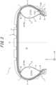
- Fig. 2 and Fig. 3 are tire width direction cross-sectional views illustrating modifications of the multi air chamber tire 1 shown in Fig. 1 .
- Each of the tires 1 of these modifications further includes ventilation members 10 which allow ventilation to the second air chambers 21.
- the ventilation member 10 may be a valve, for example.
- the ventilation member 10 is not limited to a valve, and may be any device, such as a mechanical valve or a solenoid valve, which allows ventilation to the second air chamber 21.
- Each ventilation member 10 may be disposed at any position on the tire 1.
- the ventilation member 10 may be disposed at a position where the ventilation member 10 penetrates through the inner liner 7 and the sidewall portion 3.
- the ventilation member 10 connect the second air chamber 21 and the outside of the tire 1 in a state where ventilation is allowed. Further, as illustrated in Fig. 3 , the ventilation member 10 may be disposed at a position between the first coupling portion 9a and the second coupling portion 9b, where the ventilation member 10 penetrates through the partition wall 30 (the reinforcement layer 8). In such a case, the ventilation member 10 connects the first air chamber 20 and the second air chamber 21 in a state where ventilation is allowed. In Fig. 2 and Fig. 3 , one ventilation member 10 is disposed for each of the second air chambers 21a and 21b. However, the number of ventilation members 10 is not limited to the above. The desired number of ventilation members 10 may be disposed on the tire 1 according to the application of the tire 1.
- the ventilation member 10 may be a ventilation member which allows ventilation in both directions, that is, in the filling direction to the second air chamber 21 and in the discharging direction from the second air chamber 21.
- the ventilation member 10 may be a ventilation member which allows one of ventilation in the filling direction to the second air chamber 21 or ventilation in the discharging direction from the second air chamber 21.
- the ventilation member 10 may be a ventilation member which cannot prevent ventilation in the filling direction to the second air chamber 21, but can prevent ventilation in the discharging direction from the second air chamber 21.
- the ventilation member 10 may be a ventilation member which can prevent ventilation in the filling direction to the second air chamber 21, but cannot prevent ventilation in the discharging direction from the second air chamber 21.
- the ventilation member 10 may be a check valve which can regulate ventilation in a fixed direction, or a valve including the check valve, for example.
- each of the first air chamber 20 and the two second air chambers 21a and 21b of the tire 1 is filled with air to have a prescribed internal pressure.
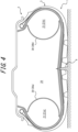
- Fig. 4 is a tire width direction cross-sectional view schematically illustrating a state where a puncture occurs in the tread portion 4 of the tire 1 illustrated in Fig. 1 .
- a puncture or the like occurs in the tread portion 4
- air in the first air chamber 20 leaks to the outside of the tire from the damaged portion where the puncture or the like occurs.
- the two second air chambers 21a and 21b are respectively defined by the partition walls 30a and 30b, thus being separated from the first air chamber 20 and hence, air does not leak to the outside of the tire from the second air chambers 21a and 21b. Therefore, the second air chambers 21a and 21b support a vehicle body, thus allowing travel after a puncture occurs. That is, the second air chambers 21a and 21b play a role substantially equivalent to the role of the side reinforcing rubber disposed on each sidewall portion of a conventional run flat tire, for example.
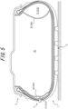
- Fig. 5 is a tire width direction cross-sectional view schematically illustrating a state where a puncture occurs in the sidewall portion 3 of the half portion of the tire which the second air chamber 21a of the tire 1 illustrated in Fig. 1 faces.
- a puncture or the like occurs in the sidewall portion 3
- air in the second air chamber 21a leaks to the outside of the tire from the damaged portion where the puncture or the like occurs.
- the first air chamber 20 and the second air chamber 21b are defined by the partition wall 30a, thus being separated from the second air chamber 21a and hence, air does not leak to the outside of the tire from the first air chamber 20 and the second air chamber 21b.
- the first air chamber 20 and the second air chamber 21b support a vehicle body, thus allowing travel after a puncture occurs.
- air in the second air chamber 21a leaks to the outside of the tire and hence, the internal pressure of the second air chamber 21a reduces to a level lower than the internal pressure of the first air chamber 20 whereby the partition wall 30a is brought into close contact with the tire inner wall surface.
- the partition wall 30a is brought into close contact with the tire inner wall surface and hence, the amount of leakage of air from the damaged portion is also reduced.
- the multi air chamber tire 1 includes the tread portion 4, the pair of bead portions 2, the pair of sidewall portions 3 extending between the tread portion 4 and the pair of the bead portions 2, and the partition walls 30 respectively provided to the half portions of the tire which are defined with respect to the tire equator plane CL, the partition walls 30 partitioning the inner cavity of the tire to form the plurality of air chambers disposed adjacent to each other.
- Each of the partition walls 30 includes the first coupling portion 9a coupled with the tire inner wall surface, and the second coupling portion 9b coupled with the tire inner wall surface at a position outward of the first coupling portion 9a in the tire radial direction.
- the first air chamber 20 is formed in a space located at a position inward of two partition walls 30 in the tire width direction, and the second air chambers 21 are formed in spaces located between the two partition walls 30 and the tire inner wall surface of the sidewall portions 3.
- Such a configuration can reduce an influence on ride comfort during normal travel, such as an increase in rigidity in the tire radial direction compared with the conventional run flat tire where the sidewall portions 3 have side reinforcing rubber.
- the tire 1 has the plurality of air chambers in the inside thereof and hence, the tire 1 allows continuous travel even when failure occurs in any one of the plurality of air chambers.
- Such a configuration it is possible to allow safe travel over a certain distance when tire failure occurs while suppressing deterioration of ride comfort. Further, such a configuration can suppress an increase in weight of the tire 1 compared with the conventional run flat tire where side reinforcing rubber is added to each sidewall portion 3 and hence, deterioration of fuel efficiency can be reduced during travel.
- each of the partition walls 30 is a member which constrains expansion and deformation. Such a configuration allows the shapes, volumes and the like of the first air chamber 20 and the second air chambers 21 of the multi air chamber tire 1 to be easily maintained.
- the bead portion 2 include the bead core 2a, and the first coupling portion 9a is coupled with the tire inner wall surface at a position outward of the bead core 2a in the tire radial direction.
- the first coupling portion 9a is coupled with the tire inner wall surface at a position outward of the bead core 2a in the tire radial direction.
- the shape of a portion of the multi air chamber tire 1 which is located at a position inward of the first coupling portion 9a of in the tire radial direction, and which is mounted on the rim may be set to be identical to the shape of a corresponding portion of a general tire.
- the multi air chamber tire 1 can be mounted on an applicable rim described later without preparing a special rim and hence, convenience of the multi air chamber tire 1 is improved.
- the second coupling portion 9b is coupled with the tire inner wall surface at a position outward of the ground contact edge of the tread portion 4 in the tire width direction.
- Such a configuration can prevent, during travel in a state where the multi air chamber tire 1 mounted, air from easily leaking from the second air chamber 21 even in a case where a puncture or the like occurs in the contact patch of the tread portion 4, which has high probability of occurrence of a puncture or the like. Accordingly, such a configuration is more effective.
- the multi air chamber tire 1 according to the present invention further include the ventilation member 10 configured to allow ventilation to the second air chamber 21.
- the ventilation member 10 configured to allow ventilation to the second air chamber 21.
- the ventilation member 10 be disposed at a position where the ventilation member 10 penetrates through the sidewall portion 3.
- Such a configuration allows air to be repeatedly filled into the second air chamber 21 directly through the ventilation member 10 even in a state where the multi air chamber tire 1 is mounted on the rim, for example, and hence, convenience of the multi air chamber tire is improved.
- the ventilation member 10 be disposed at a position where the ventilation member 10 penetrates through the partition wall 30.
- Such a configuration allows air to be filled into the first air chamber 20 via a valve or the like provided to the rim in a state where the multi air chamber tire 1 is mounted on the rim and hence, air can also be filled into the second air chamber 21 via the ventilation member 10 whereby convenience of the multi air chamber tire is improved.
- each second air chamber 21 is provided on the inner wall surface side of each of the pair of sidewall portions 3.
- the configuration is not limited to the above.
- two or more second air chambers 21 may be provided to each sidewall portion 3.
- the configuration of the tire 1 is not limited to the above.
- two second air chambers 21 may differ in at least one of volume and shape, the two second air chambers 21 being respectively provided on the inner wall surface side of the pair of sidewall portions 3
- the configuration is not limited to the above.
- the tire 1, that is, the air chamber of the tire 1 may be filled with a gas, such as nitrogen.
- a material filled into the tire 1, that is, the air chamber of the tire 1 is not limited to a gas, and fluid, such as liquid, a gel-like substance, or a granular material may be filled into the tire 1, that is, the air chamber of the tire 1.
- the tire 1 may be configured to further include a sensor which measures the internal pressure of at least one of the first air chamber 20 and the second air chambers 21, and a control device for controlling the ventilation member 10.
- the control device installed inside or outside the tire 1 can control ventilation through the ventilation member 10 when the occurrence of a puncture is determined based on the internal pressure measured by the sensor.
Landscapes
- Engineering & Computer Science (AREA)
- Mechanical Engineering (AREA)
- Tires In General (AREA)
Claims (5)
- Pneu à chambres à air multiples (1) comprenant :une partie de bande de roulement (4),une paire de parties de talon (2),une paire de parties de paroi latérale (3) s'étendant entre la partie de bande de roulement (4) et la paire de parties de talon (2), etdes parois de séparation (30) disposées respectivement sur des demi-parties d'un pneu (1) qui sont définies par rapport à un plan équatorial de pneu (CL), les parois de séparation (30) séparant une cavité intérieure du pneu (1) pour former une pluralité de chambres à air (20, 21) disposées de façon adjacente l'une à l'autre, dans lequelchacune des parois de séparation (30) inclut une première partie de couplage (9a) couplée à une surface de paroi interne du pneu et une deuxième partie de couplage (9b) couplée à la surface de paroi interne du pneu au niveau d'une position à l'extérieur de la première partie de couplage (9a) dans une direction radiale du pneu,dans un état où le pneu (1) est rempli avec un fluide, une première chambre à air (20) est formée dans un espace situé à une position à l'intérieur des parois de séparation (30) dans une direction de largeur du pneu, et une deuxième chambre à air (21) est formée dans un espace situé entre une paroi de séparation (30) des parois de séparation (30) et la surface de paroi interne du pneu d'une partie de paroi latérale (3) de la paire de parties de paroi latérale (3),la deuxième partie de couplage (9b) est couplée à la surface de paroi interne du pneu à une position à l'extérieur d'un bord de contact avec le sol de la partie de bande de roulement (4) dans la direction de largeur du pneu, etchacune des parois de séparation (30) a une résistance qui empêche une dilatation et une déformation de la paroi de séparation (30) engendrée par les pressions internes des deuxièmes chambres à air (21) lorsque les deuxièmes chambres à air (21) sont gonflées à la pression interne prescrite dans un état où la première chambre à air (20) n'est pas remplie avec un fluide,le pneu à chambres à air multiples étant caractérisé en ce quela deuxième partie de couplage (9b) est couplée à la surface de paroi interne du pneu à une position à l'intérieur de la position maximale en largeur d'une ceinture (6) agencée dans la partie de bande de roulement (4) dans la direction de largeur du pneu.
- Pneu à chambres à air multiples (1) selon la revendication 1, dans lequelchacune de la paire de parties de talon (2) inclut une tringle de talon (2a), etla première partie de couplage (9a) est couplée à la surface de paroi interne du pneu à une position à l'extérieur de la tringle de talon (2a) dans la direction radiale du pneu.
- Pneu à chambres à air multiples (1) selon la revendication 1 ou 2, comprenant en outre un élément d'aération (10) configuré pour permettre une aération vers la deuxième chambre à air (21).
- Pneu à chambres à air multiples (1) selon la revendication 3, dans lequel
l'élément d'aération (10) est disposé à une position où l'élément d'aération (10) pénètre à travers la partie de paroi latérale (3) de la paire de parties de paroi latérale (3). - Pneu à chambres à air multiples (1) selon la revendication 3 ou 4, dans lequel
l'élément d'aération (10) est disposé à une position où l'élément d'aération (10) pénètre à travers la paroi de séparation (30) des parois de séparation (30).
Applications Claiming Priority (2)
| Application Number | Priority Date | Filing Date | Title |
|---|---|---|---|
| JP2018225976A JP7146600B2 (ja) | 2018-11-30 | 2018-11-30 | 多気室タイヤ |
| PCT/JP2019/035569 WO2020110420A1 (fr) | 2018-11-30 | 2019-09-10 | Pneu à chambres multiples |
Publications (3)
| Publication Number | Publication Date |
|---|---|
| EP3888953A1 EP3888953A1 (fr) | 2021-10-06 |
| EP3888953A4 EP3888953A4 (fr) | 2022-09-07 |
| EP3888953B1 true EP3888953B1 (fr) | 2024-09-04 |
Family
ID=70852928
Family Applications (1)
| Application Number | Title | Priority Date | Filing Date |
|---|---|---|---|
| EP19890147.2A Active EP3888953B1 (fr) | 2018-11-30 | 2019-09-10 | Pneu à chambres multiples |
Country Status (5)
| Country | Link |
|---|---|
| US (1) | US11970030B2 (fr) |
| EP (1) | EP3888953B1 (fr) |
| JP (1) | JP7146600B2 (fr) |
| CN (1) | CN113165448B (fr) |
| WO (1) | WO2020110420A1 (fr) |
Families Citing this family (6)
| Publication number | Priority date | Publication date | Assignee | Title |
|---|---|---|---|---|
| JP7213074B2 (ja) * | 2018-11-30 | 2023-01-26 | 株式会社ブリヂストン | 多気室タイヤ、通気部材、多気室タイヤの内圧制御方法、及び通気部材の制御方法 |
| FR3089869A3 (fr) * | 2018-12-17 | 2020-06-19 | Michelin & Cie | Pneumatique pour véhicule comprenant une structure de rigidification. |
| EP4000958A1 (fr) | 2020-11-24 | 2022-05-25 | Rc Tech S.r.l. | Pneumatique comprenant plusieurs cavités |
| CN114132120B (zh) * | 2021-11-30 | 2023-10-10 | 路光辉 | 多气仓防爆轮胎 |
| CN114030322A (zh) * | 2021-12-22 | 2022-02-11 | 四川远星橡胶有限责任公司 | 气囊轮胎 |
| KR102831419B1 (ko) * | 2023-09-20 | 2025-07-09 | 금호타이어 주식회사 | 타이어 트레드부의 강성 보완 장치 |
Family Cites Families (39)
| Publication number | Priority date | Publication date | Assignee | Title |
|---|---|---|---|---|
| US2563788A (en) * | 1947-08-07 | 1951-08-07 | Robert B Romweber | Tubeless pneumatic tire |
| US3087528A (en) | 1958-01-30 | 1963-04-30 | Us Rubber Co | Reserve chamber tubeless tire |
| US3095027A (en) * | 1959-10-12 | 1963-06-25 | Firestone Tire & Rubber Co | Pneumatic tire |
| JPS371754B1 (fr) * | 1960-12-13 | 1962-05-12 | ||
| NL128546C (fr) * | 1965-07-13 | |||
| FR1534125A (fr) * | 1967-06-16 | 1968-07-26 | Perfectionnements aux bandages pneumatiques pour des roues de véhicules | |
| FR1538478A (fr) * | 1967-07-24 | 1968-09-06 | Uniroyal Englebert France | Enveloppe de pneumatique à carcasse radiale à flancs renforcés |
| FR2087349A5 (en) * | 1970-05-14 | 1971-12-31 | Kleber Colombes | Multi-chamber tyres - with sidewall chamber walls sized for lay-flat lay-up and lined with butyl rubber |
| FR2238603B1 (fr) * | 1973-07-27 | 1976-06-18 | Uniroyal | |
| FR2276953A1 (fr) * | 1974-07-02 | 1976-01-30 | Kleber Colombes | Pneumatique de securite |
| US3976115A (en) * | 1974-07-18 | 1976-08-24 | Uniroyal, S.A. | Pneumatic tire |
| FR2280519B1 (fr) * | 1974-07-31 | 1977-01-07 | Michelin & Cie | Perfectionnements aux enveloppes de pneumatiques |
| US5109905A (en) * | 1977-12-01 | 1992-05-05 | Lambe Donald M | Dual chamber pneumatic tire with the chambers separated by a collapsible partition wall |
| US4280546A (en) * | 1978-07-27 | 1981-07-28 | Mistretta Victor S | Multi-annular chamber, tubeless safety tire |
| JPS6176705U (fr) * | 1984-10-25 | 1986-05-23 | ||
| EP0919405A1 (fr) | 1997-11-14 | 1999-06-02 | Pirelli Pneumatici Societa' Per Azioni | Chambre à air pour pneus et son procédé de fabrication |
| JP3312880B2 (ja) | 1999-04-16 | 2002-08-12 | 住友ゴム工業株式会社 | 安全タイヤ |
| US6470935B1 (en) * | 2000-05-02 | 2002-10-29 | Fulsang Architecture Inc. | Tire having inside walls |
| JP2002067610A (ja) | 2000-08-24 | 2002-03-08 | Bridgestone Corp | 安全空気入りタイヤ・リム組立体 |
| JP4397374B2 (ja) | 2003-05-30 | 2010-01-13 | 株式会社ブリヂストン | 安全タイヤ及び安全タイヤ用空気のう |
| US20050279438A1 (en) * | 2004-06-21 | 2005-12-22 | John Onracek | Motor vehicle tire |
| KR100750215B1 (ko) * | 2004-12-27 | 2007-08-17 | 금호타이어 주식회사 | 다중 에어 쳄버를 갖는 런플랫 타이어 |
| JP2007001551A (ja) * | 2005-06-21 | 2007-01-11 | Saburo Kimura | 安全タイヤ・安全安定タイヤ |
| JP2007223477A (ja) * | 2006-02-23 | 2007-09-06 | Bridgestone Corp | タイヤ用チューブ |
| JP2008308125A (ja) * | 2007-06-18 | 2008-12-25 | Bridgestone Corp | 安全タイヤ |
| KR100860218B1 (ko) * | 2007-09-13 | 2008-09-24 | 금호타이어 주식회사 | 사이드월 보강형 런플랫 타이어 |
| KR100922287B1 (ko) * | 2008-01-14 | 2009-10-15 | 금호타이어 주식회사 | 런플랫 기능을 구비한 공기입 타이어 |
| KR20100095299A (ko) * | 2009-02-20 | 2010-08-30 | 유재천 | 격실이 형성된 튜브리스 타이어 조립체 |
| KR20110058927A (ko) * | 2009-11-27 | 2011-06-02 | 금호타이어 주식회사 | 런플랫 타이어용 튜브형 인서트러버 |
| CN102848862A (zh) * | 2012-10-02 | 2013-01-02 | 柳州市京阳节能科技研发有限公司 | 高强防泄爆耐用轮胎 |
| WO2014057282A1 (fr) * | 2012-10-12 | 2014-04-17 | Fusion Innovations Ltd | Pneumatique doté de plusieurs chambres |
| CN203438778U (zh) | 2013-09-16 | 2014-02-19 | 山东永泰化工有限公司 | 一种安全轮胎 |
| JP2015077922A (ja) * | 2013-10-18 | 2015-04-23 | 株式会社ブリヂストン | 安全タイヤ |
| CN103863023A (zh) | 2014-03-11 | 2014-06-18 | 偶烁 | 一种新型双胎连体防爆胎及漏气装置 |
| TW201741157A (zh) * | 2016-05-16 | 2017-12-01 | 王舜清 | 安全輪胎裝置 |
| KR101834926B1 (ko) * | 2016-11-29 | 2018-03-06 | 넥센타이어 주식회사 | 공기입 타이어의 사이드월 인서트 |
| EP3724004B1 (fr) * | 2017-12-11 | 2022-07-20 | Compagnie Generale Des Etablissements Michelin | Pneumatique pour vehicule avec structure de rigidification dans la cavite torique interieure |
| GB2575662A (en) * | 2018-07-18 | 2020-01-22 | Automotive Fusion Ltd | Tyre |
| JP7213074B2 (ja) * | 2018-11-30 | 2023-01-26 | 株式会社ブリヂストン | 多気室タイヤ、通気部材、多気室タイヤの内圧制御方法、及び通気部材の制御方法 |
-
2018
- 2018-11-30 JP JP2018225976A patent/JP7146600B2/ja active Active
-
2019
- 2019-09-10 EP EP19890147.2A patent/EP3888953B1/fr active Active
- 2019-09-10 US US17/293,476 patent/US11970030B2/en active Active
- 2019-09-10 WO PCT/JP2019/035569 patent/WO2020110420A1/fr not_active Ceased
- 2019-09-10 CN CN201980078633.5A patent/CN113165448B/zh active Active
Also Published As
| Publication number | Publication date |
|---|---|
| WO2020110420A1 (fr) | 2020-06-04 |
| US20220016930A1 (en) | 2022-01-20 |
| JP2020083286A (ja) | 2020-06-04 |
| CN113165448B (zh) | 2022-12-06 |
| US11970030B2 (en) | 2024-04-30 |
| JP7146600B2 (ja) | 2022-10-04 |
| CN113165448A (zh) | 2021-07-23 |
| EP3888953A1 (fr) | 2021-10-06 |
| EP3888953A4 (fr) | 2022-09-07 |
Similar Documents
| Publication | Publication Date | Title |
|---|---|---|
| EP3888953B1 (fr) | Pneu à chambres multiples | |
| JP5858069B2 (ja) | 空気入りタイヤ | |
| US11312190B2 (en) | Pneumatic tire | |
| US12109855B2 (en) | Multi air chamber tire and method for controlling internal pressure of same | |
| JP2010018123A (ja) | 空気入りタイヤ | |
| EP3599111B1 (fr) | Pneumatique | |
| JP6311810B1 (ja) | 空気入りタイヤ | |
| US20170036494A1 (en) | Side-reinforcement-type run-flat radial tire | |
| US20080006360A1 (en) | Pneumatic vehicle tire with bead reinforcer | |
| EP3978275B1 (fr) | Pneumatique | |
| JP7213073B2 (ja) | 多気室タイヤ、通気部材、多気室タイヤの内圧制御方法、及び通気部材の制御方法 | |
| JP6171501B2 (ja) | 空気入りタイヤ | |
| JP6201757B2 (ja) | 空気入りタイヤおよび空気入りタイヤの製造方法 | |
| EP1894750B1 (fr) | Vessie d'air pour pneu de sécurité et pneu de sécurité utilisant la vessie d'air | |
| JP2013169826A (ja) | 空気入りタイヤ | |
| EP4371784B1 (fr) | Pneumatique | |
| US20250018751A1 (en) | Sound absorbing tool and assembly | |
| JP2010179779A (ja) | 空気入りタイヤ | |
| EP3741582A1 (fr) | Pneu ayant une structure d'épaule | |
| CN109955660A (zh) | 充气轮胎 | |
| JP2006188176A (ja) | 空気入りタイヤ |
Legal Events
| Date | Code | Title | Description |
|---|---|---|---|
| STAA | Information on the status of an ep patent application or granted ep patent |
Free format text: STATUS: THE INTERNATIONAL PUBLICATION HAS BEEN MADE |
|
| PUAI | Public reference made under article 153(3) epc to a published international application that has entered the european phase |
Free format text: ORIGINAL CODE: 0009012 |
|
| STAA | Information on the status of an ep patent application or granted ep patent |
Free format text: STATUS: REQUEST FOR EXAMINATION WAS MADE |
|
| 17P | Request for examination filed |
Effective date: 20210324 |
|
| AK | Designated contracting states |
Kind code of ref document: A1 Designated state(s): AL AT BE BG CH CY CZ DE DK EE ES FI FR GB GR HR HU IE IS IT LI LT LU LV MC MK MT NL NO PL PT RO RS SE SI SK SM TR |
|
| DAV | Request for validation of the european patent (deleted) | ||
| DAX | Request for extension of the european patent (deleted) | ||
| A4 | Supplementary search report drawn up and despatched |
Effective date: 20220804 |
|
| RIC1 | Information provided on ipc code assigned before grant |
Ipc: B60C 17/01 20060101ALI20220729BHEP Ipc: B60C 19/12 20060101ALI20220729BHEP Ipc: B60C 29/00 20060101ALI20220729BHEP Ipc: B60C 23/00 20060101ALI20220729BHEP Ipc: B60C 5/00 20060101ALI20220729BHEP Ipc: B60C 5/22 20060101AFI20220729BHEP |
|
| REG | Reference to a national code |
Free format text: PREVIOUS MAIN CLASS: B60C0017010000 Ref country code: DE Ref legal event code: R079 Ref document number: 602019058500 Country of ref document: DE Free format text: PREVIOUS MAIN CLASS: B60C0017010000 Ipc: B60C0005220000 |
|
| GRAP | Despatch of communication of intention to grant a patent |
Free format text: ORIGINAL CODE: EPIDOSNIGR1 |
|
| STAA | Information on the status of an ep patent application or granted ep patent |
Free format text: STATUS: GRANT OF PATENT IS INTENDED |
|
| RIC1 | Information provided on ipc code assigned before grant |
Ipc: B60C 17/01 20060101ALI20240221BHEP Ipc: B60C 19/12 20060101ALI20240221BHEP Ipc: B60C 29/00 20060101ALI20240221BHEP Ipc: B60C 23/00 20060101ALI20240221BHEP Ipc: B60C 5/00 20060101ALI20240221BHEP Ipc: B60C 5/22 20060101AFI20240221BHEP |
|
| INTG | Intention to grant announced |
Effective date: 20240327 |
|
| P01 | Opt-out of the competence of the unified patent court (upc) registered |
Effective date: 20240410 |
|
| GRAS | Grant fee paid |
Free format text: ORIGINAL CODE: EPIDOSNIGR3 |
|
| GRAA | (expected) grant |
Free format text: ORIGINAL CODE: 0009210 |
|
| STAA | Information on the status of an ep patent application or granted ep patent |
Free format text: STATUS: THE PATENT HAS BEEN GRANTED |
|
| AK | Designated contracting states |
Kind code of ref document: B1 Designated state(s): AL AT BE BG CH CY CZ DE DK EE ES FI FR GB GR HR HU IE IS IT LI LT LU LV MC MK MT NL NO PL PT RO RS SE SI SK SM TR |
|
| REG | Reference to a national code |
Ref country code: GB Ref legal event code: FG4D |
|
| REG | Reference to a national code |
Ref country code: CH Ref legal event code: EP |
|
| REG | Reference to a national code |
Ref country code: IE Ref legal event code: FG4D |
|
| REG | Reference to a national code |
Ref country code: DE Ref legal event code: R096 Ref document number: 602019058500 Country of ref document: DE |
|
| REG | Reference to a national code |
Ref country code: LT Ref legal event code: MG9D |
|
| REG | Reference to a national code |
Ref country code: NL Ref legal event code: MP Effective date: 20240904 |
|
| PG25 | Lapsed in a contracting state [announced via postgrant information from national office to epo] |
Ref country code: NO Free format text: LAPSE BECAUSE OF FAILURE TO SUBMIT A TRANSLATION OF THE DESCRIPTION OR TO PAY THE FEE WITHIN THE PRESCRIBED TIME-LIMIT Effective date: 20241204 |
|
| PG25 | Lapsed in a contracting state [announced via postgrant information from national office to epo] |
Ref country code: GR Free format text: LAPSE BECAUSE OF FAILURE TO SUBMIT A TRANSLATION OF THE DESCRIPTION OR TO PAY THE FEE WITHIN THE PRESCRIBED TIME-LIMIT Effective date: 20241205 Ref country code: FI Free format text: LAPSE BECAUSE OF FAILURE TO SUBMIT A TRANSLATION OF THE DESCRIPTION OR TO PAY THE FEE WITHIN THE PRESCRIBED TIME-LIMIT Effective date: 20240904 Ref country code: PL Free format text: LAPSE BECAUSE OF FAILURE TO SUBMIT A TRANSLATION OF THE DESCRIPTION OR TO PAY THE FEE WITHIN THE PRESCRIBED TIME-LIMIT Effective date: 20240904 |
|
| PG25 | Lapsed in a contracting state [announced via postgrant information from national office to epo] |
Ref country code: BG Free format text: LAPSE BECAUSE OF FAILURE TO SUBMIT A TRANSLATION OF THE DESCRIPTION OR TO PAY THE FEE WITHIN THE PRESCRIBED TIME-LIMIT Effective date: 20240904 |
|
| PG25 | Lapsed in a contracting state [announced via postgrant information from national office to epo] |
Ref country code: LV Free format text: LAPSE BECAUSE OF FAILURE TO SUBMIT A TRANSLATION OF THE DESCRIPTION OR TO PAY THE FEE WITHIN THE PRESCRIBED TIME-LIMIT Effective date: 20240904 |
|
| PG25 | Lapsed in a contracting state [announced via postgrant information from national office to epo] |
Ref country code: HR Free format text: LAPSE BECAUSE OF FAILURE TO SUBMIT A TRANSLATION OF THE DESCRIPTION OR TO PAY THE FEE WITHIN THE PRESCRIBED TIME-LIMIT Effective date: 20240904 |
|
| PG25 | Lapsed in a contracting state [announced via postgrant information from national office to epo] |
Ref country code: ES Free format text: LAPSE BECAUSE OF FAILURE TO SUBMIT A TRANSLATION OF THE DESCRIPTION OR TO PAY THE FEE WITHIN THE PRESCRIBED TIME-LIMIT Effective date: 20240904 Ref country code: RS Free format text: LAPSE BECAUSE OF FAILURE TO SUBMIT A TRANSLATION OF THE DESCRIPTION OR TO PAY THE FEE WITHIN THE PRESCRIBED TIME-LIMIT Effective date: 20241204 |
|
| PG25 | Lapsed in a contracting state [announced via postgrant information from national office to epo] |
Ref country code: RS Free format text: LAPSE BECAUSE OF FAILURE TO SUBMIT A TRANSLATION OF THE DESCRIPTION OR TO PAY THE FEE WITHIN THE PRESCRIBED TIME-LIMIT Effective date: 20241204 Ref country code: PL Free format text: LAPSE BECAUSE OF FAILURE TO SUBMIT A TRANSLATION OF THE DESCRIPTION OR TO PAY THE FEE WITHIN THE PRESCRIBED TIME-LIMIT Effective date: 20240904 Ref country code: NO Free format text: LAPSE BECAUSE OF FAILURE TO SUBMIT A TRANSLATION OF THE DESCRIPTION OR TO PAY THE FEE WITHIN THE PRESCRIBED TIME-LIMIT Effective date: 20241204 Ref country code: LV Free format text: LAPSE BECAUSE OF FAILURE TO SUBMIT A TRANSLATION OF THE DESCRIPTION OR TO PAY THE FEE WITHIN THE PRESCRIBED TIME-LIMIT Effective date: 20240904 Ref country code: HR Free format text: LAPSE BECAUSE OF FAILURE TO SUBMIT A TRANSLATION OF THE DESCRIPTION OR TO PAY THE FEE WITHIN THE PRESCRIBED TIME-LIMIT Effective date: 20240904 Ref country code: GR Free format text: LAPSE BECAUSE OF FAILURE TO SUBMIT A TRANSLATION OF THE DESCRIPTION OR TO PAY THE FEE WITHIN THE PRESCRIBED TIME-LIMIT Effective date: 20241205 Ref country code: FI Free format text: LAPSE BECAUSE OF FAILURE TO SUBMIT A TRANSLATION OF THE DESCRIPTION OR TO PAY THE FEE WITHIN THE PRESCRIBED TIME-LIMIT Effective date: 20240904 Ref country code: ES Free format text: LAPSE BECAUSE OF FAILURE TO SUBMIT A TRANSLATION OF THE DESCRIPTION OR TO PAY THE FEE WITHIN THE PRESCRIBED TIME-LIMIT Effective date: 20240904 Ref country code: BG Free format text: LAPSE BECAUSE OF FAILURE TO SUBMIT A TRANSLATION OF THE DESCRIPTION OR TO PAY THE FEE WITHIN THE PRESCRIBED TIME-LIMIT Effective date: 20240904 |
|
| REG | Reference to a national code |
Ref country code: AT Ref legal event code: MK05 Ref document number: 1720006 Country of ref document: AT Kind code of ref document: T Effective date: 20240904 |
|
| PG25 | Lapsed in a contracting state [announced via postgrant information from national office to epo] |
Ref country code: NL Free format text: LAPSE BECAUSE OF FAILURE TO SUBMIT A TRANSLATION OF THE DESCRIPTION OR TO PAY THE FEE WITHIN THE PRESCRIBED TIME-LIMIT Effective date: 20240904 |
|
| PG25 | Lapsed in a contracting state [announced via postgrant information from national office to epo] |
Ref country code: IS Free format text: LAPSE BECAUSE OF FAILURE TO SUBMIT A TRANSLATION OF THE DESCRIPTION OR TO PAY THE FEE WITHIN THE PRESCRIBED TIME-LIMIT Effective date: 20250104 Ref country code: PT Free format text: LAPSE BECAUSE OF FAILURE TO SUBMIT A TRANSLATION OF THE DESCRIPTION OR TO PAY THE FEE WITHIN THE PRESCRIBED TIME-LIMIT Effective date: 20250106 |
|
| PG25 | Lapsed in a contracting state [announced via postgrant information from national office to epo] |
Ref country code: RO Free format text: LAPSE BECAUSE OF FAILURE TO SUBMIT A TRANSLATION OF THE DESCRIPTION OR TO PAY THE FEE WITHIN THE PRESCRIBED TIME-LIMIT Effective date: 20240904 Ref country code: SM Free format text: LAPSE BECAUSE OF FAILURE TO SUBMIT A TRANSLATION OF THE DESCRIPTION OR TO PAY THE FEE WITHIN THE PRESCRIBED TIME-LIMIT Effective date: 20240904 |
|
| PG25 | Lapsed in a contracting state [announced via postgrant information from national office to epo] |
Ref country code: EE Free format text: LAPSE BECAUSE OF FAILURE TO SUBMIT A TRANSLATION OF THE DESCRIPTION OR TO PAY THE FEE WITHIN THE PRESCRIBED TIME-LIMIT Effective date: 20240904 Ref country code: AT Free format text: LAPSE BECAUSE OF FAILURE TO SUBMIT A TRANSLATION OF THE DESCRIPTION OR TO PAY THE FEE WITHIN THE PRESCRIBED TIME-LIMIT Effective date: 20240904 |
|
| PG25 | Lapsed in a contracting state [announced via postgrant information from national office to epo] |
Ref country code: CZ Free format text: LAPSE BECAUSE OF FAILURE TO SUBMIT A TRANSLATION OF THE DESCRIPTION OR TO PAY THE FEE WITHIN THE PRESCRIBED TIME-LIMIT Effective date: 20240904 |
|
| PG25 | Lapsed in a contracting state [announced via postgrant information from national office to epo] |
Ref country code: SK Free format text: LAPSE BECAUSE OF FAILURE TO SUBMIT A TRANSLATION OF THE DESCRIPTION OR TO PAY THE FEE WITHIN THE PRESCRIBED TIME-LIMIT Effective date: 20240904 Ref country code: IT Free format text: LAPSE BECAUSE OF FAILURE TO SUBMIT A TRANSLATION OF THE DESCRIPTION OR TO PAY THE FEE WITHIN THE PRESCRIBED TIME-LIMIT Effective date: 20240904 |
|
| REG | Reference to a national code |
Ref country code: CH Ref legal event code: PL |
|
| PG25 | Lapsed in a contracting state [announced via postgrant information from national office to epo] |
Ref country code: LU Free format text: LAPSE BECAUSE OF NON-PAYMENT OF DUE FEES Effective date: 20240910 |
|
| REG | Reference to a national code |
Ref country code: DE Ref legal event code: R097 Ref document number: 602019058500 Country of ref document: DE |
|
| PG25 | Lapsed in a contracting state [announced via postgrant information from national office to epo] |
Ref country code: MC Free format text: LAPSE BECAUSE OF FAILURE TO SUBMIT A TRANSLATION OF THE DESCRIPTION OR TO PAY THE FEE WITHIN THE PRESCRIBED TIME-LIMIT Effective date: 20240904 |
|
| PG25 | Lapsed in a contracting state [announced via postgrant information from national office to epo] |
Ref country code: DK Free format text: LAPSE BECAUSE OF FAILURE TO SUBMIT A TRANSLATION OF THE DESCRIPTION OR TO PAY THE FEE WITHIN THE PRESCRIBED TIME-LIMIT Effective date: 20240904 |
|
| REG | Reference to a national code |
Ref country code: BE Ref legal event code: MM Effective date: 20240930 |
|
| PLBE | No opposition filed within time limit |
Free format text: ORIGINAL CODE: 0009261 |
|
| STAA | Information on the status of an ep patent application or granted ep patent |
Free format text: STATUS: NO OPPOSITION FILED WITHIN TIME LIMIT |
|
| PG25 | Lapsed in a contracting state [announced via postgrant information from national office to epo] |
Ref country code: BE Free format text: LAPSE BECAUSE OF NON-PAYMENT OF DUE FEES Effective date: 20240930 |
|
| PG25 | Lapsed in a contracting state [announced via postgrant information from national office to epo] |
Ref country code: CH Free format text: LAPSE BECAUSE OF NON-PAYMENT OF DUE FEES Effective date: 20240930 |
|
| PG25 | Lapsed in a contracting state [announced via postgrant information from national office to epo] |
Ref country code: IE Free format text: LAPSE BECAUSE OF NON-PAYMENT OF DUE FEES Effective date: 20240910 |
|
| 26N | No opposition filed |
Effective date: 20250605 |
|
| GBPC | Gb: european patent ceased through non-payment of renewal fee |
Effective date: 20241204 |
|
| PG25 | Lapsed in a contracting state [announced via postgrant information from national office to epo] |
Ref country code: SE Free format text: LAPSE BECAUSE OF FAILURE TO SUBMIT A TRANSLATION OF THE DESCRIPTION OR TO PAY THE FEE WITHIN THE PRESCRIBED TIME-LIMIT Effective date: 20240904 |
|
| PGFP | Annual fee paid to national office [announced via postgrant information from national office to epo] |
Ref country code: DE Payment date: 20250919 Year of fee payment: 7 |
|
| PG25 | Lapsed in a contracting state [announced via postgrant information from national office to epo] |
Ref country code: GB Free format text: LAPSE BECAUSE OF NON-PAYMENT OF DUE FEES Effective date: 20241204 |
|
| PGFP | Annual fee paid to national office [announced via postgrant information from national office to epo] |
Ref country code: FR Payment date: 20250922 Year of fee payment: 7 |
|
| PG25 | Lapsed in a contracting state [announced via postgrant information from national office to epo] |
Ref country code: CY Free format text: LAPSE BECAUSE OF FAILURE TO SUBMIT A TRANSLATION OF THE DESCRIPTION OR TO PAY THE FEE WITHIN THE PRESCRIBED TIME-LIMIT; INVALID AB INITIO Effective date: 20190910 |
|
| PG25 | Lapsed in a contracting state [announced via postgrant information from national office to epo] |
Ref country code: HU Free format text: LAPSE BECAUSE OF FAILURE TO SUBMIT A TRANSLATION OF THE DESCRIPTION OR TO PAY THE FEE WITHIN THE PRESCRIBED TIME-LIMIT; INVALID AB INITIO Effective date: 20190910 |