EP4000958A1 - Pneumatique comprenant plusieurs cavités - Google Patents
Pneumatique comprenant plusieurs cavités Download PDFInfo
- Publication number
- EP4000958A1 EP4000958A1 EP21180352.3A EP21180352A EP4000958A1 EP 4000958 A1 EP4000958 A1 EP 4000958A1 EP 21180352 A EP21180352 A EP 21180352A EP 4000958 A1 EP4000958 A1 EP 4000958A1
- Authority
- EP
- European Patent Office
- Prior art keywords
- bead
- chamber
- tire
- valve
- bead seat
- Prior art date
- Legal status (The legal status is an assumption and is not a legal conclusion. Google has not performed a legal analysis and makes no representation as to the accuracy of the status listed.)
- Withdrawn
Links
- 239000011324 bead Substances 0.000 claims abstract description 283
- 230000000284 resting effect Effects 0.000 claims abstract description 14
- 238000005096 rolling process Methods 0.000 claims abstract description 11
- 238000000034 method Methods 0.000 claims description 15
- 239000012530 fluid Substances 0.000 claims description 4
- 230000000694 effects Effects 0.000 description 10
- 230000008901 benefit Effects 0.000 description 8
- 238000010276 construction Methods 0.000 description 6
- 230000035882 stress Effects 0.000 description 6
- 238000010521 absorption reaction Methods 0.000 description 5
- 238000006243 chemical reaction Methods 0.000 description 5
- 238000009826 distribution Methods 0.000 description 5
- 238000004519 manufacturing process Methods 0.000 description 5
- 239000002861 polymer material Substances 0.000 description 4
- 230000009467 reduction Effects 0.000 description 4
- 240000005702 Galium aparine Species 0.000 description 3
- 230000015556 catabolic process Effects 0.000 description 3
- 238000006731 degradation reaction Methods 0.000 description 3
- 238000011161 development Methods 0.000 description 3
- 230000018109 developmental process Effects 0.000 description 3
- 239000000463 material Substances 0.000 description 3
- 239000002184 metal Substances 0.000 description 3
- 238000005457 optimization Methods 0.000 description 3
- 230000003068 static effect Effects 0.000 description 3
- 241000272201 Columbiformes Species 0.000 description 2
- 230000001133 acceleration Effects 0.000 description 2
- 239000004744 fabric Substances 0.000 description 2
- 230000001788 irregular Effects 0.000 description 2
- 238000004806 packaging method and process Methods 0.000 description 2
- 230000008569 process Effects 0.000 description 2
- 239000000047 product Substances 0.000 description 2
- 230000002441 reversible effect Effects 0.000 description 2
- 239000011265 semifinished product Substances 0.000 description 2
- 230000003213 activating effect Effects 0.000 description 1
- 230000032683 aging Effects 0.000 description 1
- 238000004458 analytical method Methods 0.000 description 1
- 230000002547 anomalous effect Effects 0.000 description 1
- 230000033228 biological regulation Effects 0.000 description 1
- 230000005540 biological transmission Effects 0.000 description 1
- 125000000484 butyl group Chemical group [H]C([*])([H])C([H])([H])C([H])([H])C([H])([H])[H] 0.000 description 1
- 230000008859 change Effects 0.000 description 1
- 239000003795 chemical substances by application Substances 0.000 description 1
- 230000000295 complement effect Effects 0.000 description 1
- 150000001875 compounds Chemical class 0.000 description 1
- 238000013016 damping Methods 0.000 description 1
- 230000007423 decrease Effects 0.000 description 1
- 230000001419 dependent effect Effects 0.000 description 1
- 238000013461 design Methods 0.000 description 1
- 238000009792 diffusion process Methods 0.000 description 1
- 238000005516 engineering process Methods 0.000 description 1
- 238000002474 experimental method Methods 0.000 description 1
- 239000000945 filler Substances 0.000 description 1
- 230000004927 fusion Effects 0.000 description 1
- 230000006872 improvement Effects 0.000 description 1
- 230000003993 interaction Effects 0.000 description 1
- 230000000670 limiting effect Effects 0.000 description 1
- 238000012886 linear function Methods 0.000 description 1
- 238000005259 measurement Methods 0.000 description 1
- 238000000691 measurement method Methods 0.000 description 1
- 229920000642 polymer Polymers 0.000 description 1
- 230000002028 premature Effects 0.000 description 1
- 238000003825 pressing Methods 0.000 description 1
- 230000009290 primary effect Effects 0.000 description 1
- 238000012545 processing Methods 0.000 description 1
- 230000007425 progressive decline Effects 0.000 description 1
- 230000001681 protective effect Effects 0.000 description 1
- 230000003014 reinforcing effect Effects 0.000 description 1
- 238000007789 sealing Methods 0.000 description 1
- 230000006641 stabilisation Effects 0.000 description 1
- 238000011105 stabilization Methods 0.000 description 1
- 239000000725 suspension Substances 0.000 description 1
- 239000004753 textile Substances 0.000 description 1
- 238000012546 transfer Methods 0.000 description 1
Images




Classifications
-
- B—PERFORMING OPERATIONS; TRANSPORTING
- B60—VEHICLES IN GENERAL
- B60C—VEHICLE TYRES; TYRE INFLATION; TYRE CHANGING; CONNECTING VALVES TO INFLATABLE ELASTIC BODIES IN GENERAL; DEVICES OR ARRANGEMENTS RELATED TO TYRES
- B60C17/00—Tyres characterised by means enabling restricted operation in damaged or deflated condition; Accessories therefor
- B60C17/009—Tyres characterised by means enabling restricted operation in damaged or deflated condition; Accessories therefor comprising annular protrusions projecting into the tyre cavity
-
- B—PERFORMING OPERATIONS; TRANSPORTING
- B60—VEHICLES IN GENERAL
- B60C—VEHICLE TYRES; TYRE INFLATION; TYRE CHANGING; CONNECTING VALVES TO INFLATABLE ELASTIC BODIES IN GENERAL; DEVICES OR ARRANGEMENTS RELATED TO TYRES
- B60C17/00—Tyres characterised by means enabling restricted operation in damaged or deflated condition; Accessories therefor
- B60C17/01—Tyres characterised by means enabling restricted operation in damaged or deflated condition; Accessories therefor utilising additional inflatable supports which become load-supporting in emergency
-
- B—PERFORMING OPERATIONS; TRANSPORTING
- B60—VEHICLES IN GENERAL
- B60C—VEHICLE TYRES; TYRE INFLATION; TYRE CHANGING; CONNECTING VALVES TO INFLATABLE ELASTIC BODIES IN GENERAL; DEVICES OR ARRANGEMENTS RELATED TO TYRES
- B60C5/00—Inflatable pneumatic tyres or inner tubes
- B60C5/20—Inflatable pneumatic tyres or inner tubes having multiple separate inflatable chambers
- B60C5/22—Inflatable pneumatic tyres or inner tubes having multiple separate inflatable chambers the chambers being annular
Definitions
- the present invention relates to a tire, and in particular, to a tire having a plurality of inflation chambers.
- the structure of a tire basically includes the following elements:
- Carcass made of cord plies (generally arranged in a radial direction in road tires) embedded in a rubber compound, it has the task of containing the pressurized air (which serves the vertical load bearing function) and allowing the transmission of the stresses exchanged between the tread and the ground to the rim through the bead zone.
- Bead it is the zone where the tire is constrained to the wheel rim. It generally consists of a metal ring coupled to a bead filling zone for filling highly rigid polymer material which binds it to the carcass and thus allows the transfer of stresses. It is covered with a zone referred to as a "bead end" which seals the interface between the rim and the tire, thus preventing air from escaping (tubeless tire).
- Belts generally consisting of rubberized fabric or metal cords arranged according to an "intersection" angle and almost always surmounted by one or more layers of fabric arranged at zero degrees.
- the belts allow to provide torsional stiffness to the tread pattern and to transmit the tire/ground interchange forces (lateral cornering and traction/braking forces)
- Tread tire rolling surface. Made of high-adhesion polymer materials with wear resistance properties. It is variously sculpted ("tread pattern") to optimize grip, resistance to hydroplaning on wet surfaces, rolling noise, and mileage performance features (wear).
- Flank it is the zone protecting carcass and bead from impacts and external agents, and confers aging and fatigue resistance qualities.
- the flank zone is the element of greater vertical and lateral flexibility. Therefore, it serves a primary function in ensuring the vertical deformability of the tire and the stiffness features thereof with respect to the lateral loads (lateral stability).
- the pressurized air contained inside the tire serves the primary function of ensuring the structural support of the vertical load on the wheel and tensioning the tire structure itself, in order to generate and transmit the stresses (force and torque) exchanged with the ground.
- Each tire has an optimal inflation pressure as a function of the features thereof (size, materials, construction, etc.) and the specific application (vehicle, load transported, etc.).
- the correct inflation pressure is specified by the vehicle or tire manufacturer (generally a nominal value of ⁇ 0.1 bar).
- the ideal inflation pressure thus allows to optimize the "inflated" profile of the flank and of the tread crown and to optimize the distribution of the contact pressures between the tire and the ground.
- the ideal inflation pressure is that leading to the best compromise between the different performance features of the tire, in particular the ability to absorb obstacles (vertical vehicle comfort) and to generate high longitudinal and lateral forces (vehicle handling).
- a deflated tire loses the vertical load support and drivability features thereof (directionality, cornering stiffness, etc.) to the point of running into the issue of debeading from the rim or of premature structural fatigue failure.
- a tire subjected to a vertical or lateral force takes a deformed shape.
- the stiffness of the "equivalent vertical spring” is generally defined “tire spring rate” and is one of the fundamental magnitudes for the purposes of the vertical dynamic behavior of the wheel coupled to the vehicle suspension and therefore for the purposes of the vertical comfort and road holding features of the vehicle (absorption of obstacles and capability of keeping the wheel in contact with the ground).
- pressurized air is the most significant structural element in supporting the vertical load.
- the first measurement with respect to the vertical and lateral features is carried out statically (i.e., without the wheel rolling).
- the actual advancement direction of the wheel forms an angle with respect to the center plane of the rim, referred to as the cornering angle or tyre slip angle.
- the characteristic lateral force vs cornering angle is linear at least in the first part (i.e., for low cornering angles, i.e., for limited lateral forces and therefore limited lateral accelerations of the vehicle).
- the slope of the characteristic "Lateral force vs cornering angle" curve is defined as "cornering stiffness" and is one of the primary features of the tire to determine the handling performance of the vehicle.
- the cornering stiffness of the tire may be schematized as the sum of two springs in series: the relative one, due to the structural contribution (carcass, bead, flanks tensioned by the inflation pressure) and the one due to the contribution of the tread unit (belts and tread band).
- the longitudinal force is a function of the "longitudinal sliding" and for a first phase of the longitudinal dynamics it is a linear function.
- the inflation pressure has a primary effect in determining the related feature (sliding stiffness).
- the inflation pressure thus plays a primary role both in terms of vertical comfort and road holding features and in terms of tire cornering features, and therefore in terms of vehicle handling behavior.
- said element consists of a rubber chamber which is expandable on the flanks but is constrained, according to the radial dimension, within a certain diameter by resistant elements (resistant cords of textile material embedded in the rubbery material of the secondary chamber which allow to restrain the circumferential dimension).
- Said secondary chamber is inserted into the cavity formed between the rim and the tire and is inflated with air through a specific secondary valve present on the rim.
- the upper part of the tire i.e., the tread zone, the connection zone between the tread and the flank ("sidewall"), and the upper part of the flanks themselves remain instead subject to the inflation pressure of the tire itself.
- the presence of the secondary element allows to obtain two distinct volumes inside the tire which allow to provide the tire with load-bearing features in case of a puncture (run-flat).
- the secondary chamber by pressing with a strong pressure against the tire bead and thus ensuring air tightness and avoiding debeading, allows the tire to work at highly low pressures with excellent obstacle absorption capacity, large pattern areas, and thus grip on muddy, slimy, and uneven surfaces, and great puncture resistance (the best known systems are Schwalbe ProCore and DeanEasy).
- the secondary chamber is an actual internal tire ("inner liner") the purpose of which is not to modify the dynamic features of the actual tire, but to ensure lift and safety in case of a puncture (run-flat effect).
- the bead zone of the secondary chamber presses against the bead zone of the external tire.
- the second valve is positioned precisely at this interface between the two beads, which also allows the external tire to be pressurized (see the Goodyear Tires Racing Manual for assembly details). Therefore, to allow the passage of air, the walls of the liner are shaped with grooves of various geometries. See US5273093 , US06688359 , US20090000714 .
- the inner liner does not interact (if not negligibly) with the tire in the "usual" vehicle handling steps.
- bead seat chamber with support bead allows to obtain two distinct volumes inside the tire inflated up to different pressure values, and to optimize the vertical, lateral, cornering, tractive/braking performance features by independently adjusting the two different inflation pressure values ("bi-modal tire").
- the present double chamber solution with bead seat with support bead allows to obtain geometric and mechanical features (inflated profile, pressure distribution under the pattern area, stiffness, etc.) and therefore comfort, road holding and handling performances (vertical, cornering lateral, longitudinal under torque, combined, etc.) not possible with a traditional tire, i.e., without the presence of the secondary chamber.
- the bi-modal tire allows to:
- Such springs will have different stiffness values, which will be a function of the respective inflation pressures of the two air volumes.
- the presence of the bead seat chamber and of the bead with a resting surface may strongly stiffen that part of the flank close to the bead zone and may reduce the height of the most flexible zone of the tire flank.
- the adequate setting of the pressure inside the bead seat chamber allows to provide the tire with features more or less close to those of a lowered tire.
- the present invention allows, by appropriately setting the values of the two distinct inflation pressures, to optimize the desired performance features as a function of the specific use and to make the tire itself more adaptable and "adjustable".
- the bead seat chamber with the bead may allow to ensure limited vertical load support features and to prevent the sudden debeading from the rim.
- the bead seat chamber with the bead confers "run-flat" features to the tire, even if, obviously, for short mileage, low speed, and performance to be expressed.
- Radial direction R-R is defined below as a direction orthogonal to the tread 3 which entirely rests on a ground, for example a road.
- the direction transverse to the radial direction Y-Y or axial direction A-A is defined as a direction parallel to the ground or road or a direction parallel to the vehicle wheel rotation axis.
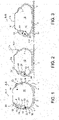
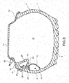
- a tire 1 comprises a tire carcass 2 on which a tread 3 with two opposite shoulders 4, 5 is arranged.
- flank 6 or 7 extends, ending in a bead 8 or 9 adapted to cooperate with an external bead surface 10 or 11 thereof with an edge 12 or 13 of a channel 14 of a rim 15 of a wheel 100 of a vehicle.
- Said tread 3 and said flanks 6, 7 embrace a main chamber 16 on at least three sides.
- Each of said flanks 6 or 7 comprises an internal 17 and an external 18 flank surface.
- Said tire 1 further comprises at least one bead seat wall 19 which is connected to two attachment portions 20, 21, separate from each other, of the internal surface 17 of at least one of said flanks 6 or 7, forming a bead seat chamber 22 with said at least one flank 6 or 7.
- One of said attachment portions 20 is placed close to the bead 10 or 11 at which said at least one flank 6 or 7 ends.
- Said bead 10 or 11 placed close to said attachment portion 20 comprises a bead projection 23.
- Said bead projection 23 protrudes from the opposite side of said external bead surface 8 or 9 into said main chamber 16.
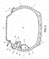
- Said bead projection 23 forms a bead resting surface 24 which is connected to said at least one flank 6 or 7 and faces said bead seat wall 19 so that when said tire 1 is statically and/or dynamically stressed by the rolling of the wheel 100 of a vehicle, it allows the support of said bead seat wall 19 on said bead resting surface 24.
- said bead seat wall 19 and said flank 6 or 7 form said bead seat chamber 22 entirely delimited by said bead seat wall 19 and said internal flank surface 17.
- said bead seat wall 19 is connected to said flank 6 or 7 substantially in a direction orthogonal to said internal flank surface 17.
- said bead resting surface 24 is connected to said flank 6 or 7 substantially in a direction orthogonal to said internal flank surface 17.
- only one flank 6 or 7 is connected to said bead seat wall 19.
- only one flank 6 is connected to said bead seat wall 19 and it is the external flank 6 which will be mounted on the rim 15 so as to remain on the side externally facing the vehicle on which the wheel 100 will be mounted.
- said bead projection 23 is hollow and forms a bead chamber 25, in which said bead chamber 25 is closed by a bead wall 26.
- a bead seat valve 27 is provided for the inflation and deflation of the bead seat chamber 22.
- a bead seat valve 27 is provided for the inflation and deflation of the bead seat chamber 22; in which said bead seat valve 27 crosses said flank 6 or 7 and allows the inflation and deflation of the bead seat chamber 22 from outside the tire 1 even when this is mounted on a rim 15.
- a bead seat valve 27 is provided for the inflation and deflation of the bead seat chamber 22; in which said bead seat valve 27 crosses said bead seat wall 19 and allows the inflation and deflation of the bead seat chamber 22 from the interior of the main chamber 16.
- a bead valve 28 is provided for the inflation and deflation of the bead chamber 25.
- a bead valve 28 is provided for the inflation and deflation of the bead chamber 25; in which said bead valve 28 crosses said flank 6 or 7 and allows the inflation and deflation of the bead chamber 25 from outside the tire 1 even when this is mounted on a rim 15.
- a bead valve 28 is provided for the inflation and deflation of the bead chamber 25; in which said bead valve 28 crosses said bead wall 26 and allows the inflation and deflation of the bead chamber 25 from the interior of the main chamber 16.
- a valve 29 between chambers is provided, which crosses said bead wall 26 and said bead seat wall 19, putting said bead chamber 25 and said bead seat chamber 22 into fluid connection for the inflation and deflation of the bead seat chamber 22.
- a valve 29 between chambers is provided, which crosses said bead wall 26 and said bead seat wall 19, putting said bead chamber 25 and said bead seat chamber 22 into fluid connection, in which said valve 29 between chambers is a one-way valve for the inflation of the bead seat chamber 22.
- a bead seat valve 27 is provided for the deflation of the bead seat chamber 22; in which said bead seat valve 27 crosses said bead seat wall 19 and is a one-way valve which allows the deflation of the bead seat chamber 22 in said main chamber 16.
- the present invention also relates to a wheel 100 of a vehicle, comprising at least one tire as described in any one of the embodiments described above, as well as a rim 15.
- said rim 15 is a standard rim provided with a main inflation and deflation valve 30 or a main valve for the inflation and deflation of the main chamber 16.
- said rim 15 comprises a rim channel 14 delimited by two opposite rim edges 12, 13. Said main chamber 16 is embraced by said tread 3, said flanks 6, 7, and said rim channel 14.
- the present invention also relates to a method for inflating a tire 1, including at least the following steps
- the present invention also relates to a method for inflating a tire 1, including at least the steps of:
- the present invention also relates to a method for inflating a tire 1, including at least the following steps:
- the present invention also relates to a method for inflating a tire 1, including at least the following steps:
- Cavities are obtained inside the structure of the external flank 6 or 7 of the tire 1, which, once pressurized (p2), become actual rigid "pneumatic bead seats" 22 such as to increase the flexural stiffness of the flank 6 or 7 itself.
- Such pneumatic bead seats 22 have a privileged location at the external surface of the flank itself or at the internal surface of the external flank of the tire.
- these bead seats 22 have been pressurized (p2), they increase the flexural resistant moment of the affected flank zone 6 or 7 and the related overall flexural stiffness of the flank 6, for example the external one.
- flank 6 or 7 thus stiffened may affect all aspects of vehicle dynamics already for low levels of stress, i.e., lateral acceleration (linear zone of the driving behavior).
- Such bead seats or bead seat chambers 22 may be preferably integrated either in the "inner liner" (the inner liner is the rubbery layer (butyl) which forms the internal surface of the tire 1 and which has the task of making the tire impermeable to the passage of air) or coupled to the layers of polymer material forming the external zone of the flank 6 or 7, or in the structure of the tire carcass 2. Therefore, from the point of view of the manufacturing process, these are specific semi-finished products which are prepared before the step of packaging the tire 1.
- Such semi-finished products may already be equipped with a micro-valve 27 to be coupled (always in the first packaging step) to the ring and filling of the bead 10 or 11 to form the "air intake" duct accessible from outside.
- the "secondary valve module" or bead seat valve 27, suitably sized to be integrated with the various elements of the flank 6 or 7 of the tire 1, may in fact be incorporated into the bead zone (consisting of the generally metal sealing ring and of the filling zone (bead filler) of the bead 10 or 11 itself), which may be considered as an infinitely rigid constraint element.
- the secondary valve module or bead seat valve 27 may also be suitably miniaturized and may incorporate a resistant element suitably sized and capable of absorbing and damping any impacts (usually against the sidewalk) to which this module may be exposed.
- the valve module and the protective resistant element may be suitably recessed and further protected externally by the rim-saving curb generally present on the external flank of the tire 1.
- the secondary valve module 27 itself may also integrate a specific pressure sensor with a system for transmitting the data (pressure) to a suitable acquisition and processing system.
- an actual internal secondary chamber may be made, consisting of a liner, suitably reinforced and therefore with controlled deformability as a function of the secondary pressure p2 of the bead seat chamber 22.
- the bead seat chamber 22 is squeezed between the external flank 6 of the tire 1 and the bead 10, thus originating the effect of a "reaction wedge” and thus exerting the specific pressure (p2 > p1) on the affected portion of the external flank 6 of the tire 1.
- the bead seat chamber 22 limits the deformability of the affected zone of the external flank 6 on which it acts.
- Such an affected flank zone may be more or less extended, depending on the geometry of the elements, the deformation state of the tire 1 (i.e., the state of stress), and the inflation pressures of the main chamber 16 and of the bead seat chamber 22.
- the manufacturing process may be conceived on an industrial scale since the bead seat chamber 22 and the secondary valve module 27 may be directly placed during the step of "structural forming process" of the tire 1.
- the inflated profile of the tire 1 not subjected to stress remains in perfect balance under the primary inflation pressure p1.
- the present invention collects and optimizes the many considerations resulting from the previous studies developed in recent years.
- the tire has an increased component complexity, it is believed that the solution is achievable with a specific design of the product (tire) and of the manufacturing process.
- the present invention is applied to a usual wheel rim 15.
- Construction solutions may also be developed with a rim specially designed, including an optimized secondary rim/chamber reaction zone.
- the present invention therefore allows to:
- the (business) assumption of the invention is that preferably no de-standardization of the wheel rim is provided.
- This special tire 1 described here, in any of the embodiments, may be mounted on any standard rim.
- the main chamber 16 is always inflated (and deflated) through the standard valve 30 (of the channel) of the rim.
- the inflation pressure values preferably respect the following inequality: bead chamber pressure> bead seat chamber pressure> main chamber pressure.
- Such bead chamber pressure, bead seat chamber pressure, and main chamber pressure may be continuously adjusted/modulated when at least one of said bead seat valves 27, bead valve 28 and valve between chambers 29 are adjustable or controllable, thereby making such a tire an "active" component, which can be integrated into the electronic handling and comfort control systems of the vehicle.
Landscapes
- Engineering & Computer Science (AREA)
- Mechanical Engineering (AREA)
- Tires In General (AREA)
Applications Claiming Priority (1)
| Application Number | Priority Date | Filing Date | Title |
|---|---|---|---|
| IT202000028163 | 2020-11-24 |
Publications (1)
| Publication Number | Publication Date |
|---|---|
| EP4000958A1 true EP4000958A1 (fr) | 2022-05-25 |
Family
ID=74557133
Family Applications (1)
| Application Number | Title | Priority Date | Filing Date |
|---|---|---|---|
| EP21180352.3A Withdrawn EP4000958A1 (fr) | 2020-11-24 | 2021-06-18 | Pneumatique comprenant plusieurs cavités |
Country Status (3)
| Country | Link |
|---|---|
| EP (1) | EP4000958A1 (fr) |
| DE (1) | DE212021000510U1 (fr) |
| WO (1) | WO2022112883A1 (fr) |
Citations (14)
| Publication number | Priority date | Publication date | Assignee | Title |
|---|---|---|---|---|
| US2898969A (en) | 1957-03-11 | 1959-08-11 | Fred B Pfeiffer | Stabilizer means |
| FR2087349A5 (en) | 1970-05-14 | 1971-12-31 | Kleber Colombes | Multi-chamber tyres - with sidewall chamber walls sized for lay-flat lay-up and lined with butyl rubber |
| FR2276953A1 (fr) * | 1974-07-02 | 1976-01-30 | Kleber Colombes | Pneumatique de securite |
| US3994329A (en) | 1974-05-24 | 1976-11-30 | Pneumatiques, Caoutchouc Manufacture Et Plastiques Kleber-Colombes | Safety tire for vehicles |
| DE2526758A1 (de) * | 1975-06-14 | 1976-12-30 | Hans Wimmer | Fahrzeugluftreifen mit notlaufvorrichtung vorzugsweise fuer tiefbett-felgen |
| US4995438A (en) | 1989-11-02 | 1991-02-26 | The Goodyear Tire & Rubber Company | Multi-chambered pneumatic tire and wheel assembly having an inner tire and an outer tire |
| US5273093A (en) | 1992-12-17 | 1993-12-28 | Hoosier Racing Tire Corp. | Racing tire assembly |
| US6186206B1 (en) * | 1995-12-18 | 2001-02-13 | Honda Giken Kogyo Kabushiki Kaisha | Tire tube with pinch protection |
| US6688359B2 (en) | 2001-08-31 | 2004-02-10 | Michelin Recherche Et Technique, S.A. | Pneumatic inner liner for a tire |
| US20090000714A1 (en) | 2007-06-28 | 2009-01-01 | Toyo Tire & Rubber Co., Ltd. | Pneumatic Tire and Tire Assembly |
| KR100922287B1 (ko) | 2008-01-14 | 2009-10-15 | 금호타이어 주식회사 | 런플랫 기능을 구비한 공기입 타이어 |
| WO2014057282A1 (fr) | 2012-10-12 | 2014-04-17 | Fusion Innovations Ltd | Pneumatique doté de plusieurs chambres |
| KR101834926B1 (ko) | 2016-11-29 | 2018-03-06 | 넥센타이어 주식회사 | 공기입 타이어의 사이드월 인서트 |
| WO2020110420A1 (fr) | 2018-11-30 | 2020-06-04 | 株式会社ブリヂストン | Pneu à chambres multiples |
Family Cites Families (1)
| Publication number | Priority date | Publication date | Assignee | Title |
|---|---|---|---|---|
| DE1188463B (de) | 1958-08-23 | 1965-03-04 | Continental Gummi Werke Ag | Luftreifen fuer Fahrzeuge |
-
2021
- 2021-06-18 EP EP21180352.3A patent/EP4000958A1/fr not_active Withdrawn
- 2021-11-02 DE DE212021000510.1U patent/DE212021000510U1/de active Active
- 2021-11-02 WO PCT/IB2021/060129 patent/WO2022112883A1/fr not_active Ceased
Patent Citations (15)
| Publication number | Priority date | Publication date | Assignee | Title |
|---|---|---|---|---|
| US2898969A (en) | 1957-03-11 | 1959-08-11 | Fred B Pfeiffer | Stabilizer means |
| FR2087349A5 (en) | 1970-05-14 | 1971-12-31 | Kleber Colombes | Multi-chamber tyres - with sidewall chamber walls sized for lay-flat lay-up and lined with butyl rubber |
| US3994329A (en) | 1974-05-24 | 1976-11-30 | Pneumatiques, Caoutchouc Manufacture Et Plastiques Kleber-Colombes | Safety tire for vehicles |
| FR2276953A1 (fr) * | 1974-07-02 | 1976-01-30 | Kleber Colombes | Pneumatique de securite |
| GB1507082A (en) | 1974-07-02 | 1978-04-12 | Kleber Colombes | Pneumatic tyres |
| DE2526758A1 (de) * | 1975-06-14 | 1976-12-30 | Hans Wimmer | Fahrzeugluftreifen mit notlaufvorrichtung vorzugsweise fuer tiefbett-felgen |
| US4995438A (en) | 1989-11-02 | 1991-02-26 | The Goodyear Tire & Rubber Company | Multi-chambered pneumatic tire and wheel assembly having an inner tire and an outer tire |
| US5273093A (en) | 1992-12-17 | 1993-12-28 | Hoosier Racing Tire Corp. | Racing tire assembly |
| US6186206B1 (en) * | 1995-12-18 | 2001-02-13 | Honda Giken Kogyo Kabushiki Kaisha | Tire tube with pinch protection |
| US6688359B2 (en) | 2001-08-31 | 2004-02-10 | Michelin Recherche Et Technique, S.A. | Pneumatic inner liner for a tire |
| US20090000714A1 (en) | 2007-06-28 | 2009-01-01 | Toyo Tire & Rubber Co., Ltd. | Pneumatic Tire and Tire Assembly |
| KR100922287B1 (ko) | 2008-01-14 | 2009-10-15 | 금호타이어 주식회사 | 런플랫 기능을 구비한 공기입 타이어 |
| WO2014057282A1 (fr) | 2012-10-12 | 2014-04-17 | Fusion Innovations Ltd | Pneumatique doté de plusieurs chambres |
| KR101834926B1 (ko) | 2016-11-29 | 2018-03-06 | 넥센타이어 주식회사 | 공기입 타이어의 사이드월 인서트 |
| WO2020110420A1 (fr) | 2018-11-30 | 2020-06-04 | 株式会社ブリヂストン | Pneu à chambres multiples |
Also Published As
| Publication number | Publication date |
|---|---|
| DE212021000510U1 (de) | 2023-08-18 |
| WO2022112883A1 (fr) | 2022-06-02 |
Similar Documents
| Publication | Publication Date | Title |
|---|---|---|
| CA2393684C (fr) | Pneumatique souple a support structurel | |
| CA2525982C (fr) | Pneumatique non gonflable | |
| EP2658733B1 (fr) | Pneu semi-pneumatique (pneu "intire") | |
| EP1420964B1 (fr) | Pneu non pneumatique | |
| US20030071513A1 (en) | Variable-diameter wheel-and-tire apparatus for motor vehicles | |
| US10682891B2 (en) | Extended-mobility cross-ply or radial tire | |
| US6491076B1 (en) | Triangular bead configuration for pneumatic tire with extended load carrying capacity | |
| JP4107961B2 (ja) | 空気入り安全タイヤ | |
| CA2412644A1 (fr) | Pneumatique souple a support structurel muni d'une carcasse diagonale | |
| EP0897814B1 (fr) | Système de roulage à plat pour motos | |
| EP1491364B1 (fr) | Pneumatique | |
| US20040025998A1 (en) | Tire wall gauges to optimize runflat tire ride comfort | |
| CN100404286C (zh) | 充气安全轮胎 | |
| US6758928B2 (en) | Method of forming pneumatic radial tire including tread having asymmetric profile | |
| US6443201B1 (en) | Pneumatic tire with extended load carrying capacity | |
| US6516845B2 (en) | Support device within a tire cavity to provide runflat capability | |
| WO2014057282A1 (fr) | Pneumatique doté de plusieurs chambres | |
| WO2022112883A1 (fr) | Pneu présentant une pluralité de chambres | |
| EP0393965B1 (fr) | Pneumatiques à carcasse radiale ayant des performances perfectionnées | |
| US8955565B2 (en) | Suspension system for vehicle and tire for vehicle | |
| JP3980456B2 (ja) | タイヤ/ホイール組立体及びランフラット用支持体 | |
| JPH03148303A (ja) | スポンジ付チューブ | |
| WO2004054822A1 (fr) | Ensemble roue et pneumatique sans chambre a air | |
| US20070246143A1 (en) | Mounted Assembly for Heavy Vehicles | |
| AU2001251653B2 (en) | Structurally supported resilient tire with bias ply carcass |
Legal Events
| Date | Code | Title | Description |
|---|---|---|---|
| PUAI | Public reference made under article 153(3) epc to a published international application that has entered the european phase |
Free format text: ORIGINAL CODE: 0009012 |
|
| STAA | Information on the status of an ep patent application or granted ep patent |
Free format text: STATUS: THE APPLICATION HAS BEEN PUBLISHED |
|
| AK | Designated contracting states |
Kind code of ref document: A1 Designated state(s): AL AT BE BG CH CY CZ DE DK EE ES FI FR GB GR HR HU IE IS IT LI LT LU LV MC MK MT NL NO PL PT RO RS SE SI SK SM TR |
|
| STAA | Information on the status of an ep patent application or granted ep patent |
Free format text: STATUS: REQUEST FOR EXAMINATION WAS MADE |
|
| 17P | Request for examination filed |
Effective date: 20220913 |
|
| RBV | Designated contracting states (corrected) |
Designated state(s): AL AT BE BG CH CY CZ DE DK EE ES FI FR GB GR HR HU IE IS IT LI LT LU LV MC MK MT NL NO PL PT RO RS SE SI SK SM TR |
|
| STAA | Information on the status of an ep patent application or granted ep patent |
Free format text: STATUS: THE APPLICATION IS DEEMED TO BE WITHDRAWN |
|
| 18D | Application deemed to be withdrawn |
Effective date: 20240103 |