EP3889383A1 - Befestigungsvorrichtung eines fensterrahmens - Google Patents
Befestigungsvorrichtung eines fensterrahmens Download PDFInfo
- Publication number
- EP3889383A1 EP3889383A1 EP21166242.4A EP21166242A EP3889383A1 EP 3889383 A1 EP3889383 A1 EP 3889383A1 EP 21166242 A EP21166242 A EP 21166242A EP 3889383 A1 EP3889383 A1 EP 3889383A1
- Authority
- EP
- European Patent Office
- Prior art keywords
- fixing
- frame
- bracket
- wall
- longitudinal
- Prior art date
- Legal status (The legal status is an assumption and is not a legal conclusion. Google has not performed a legal analysis and makes no representation as to the accuracy of the status listed.)
- Granted
Links
Images





Classifications
-
- E—FIXED CONSTRUCTIONS
- E06—DOORS, WINDOWS, SHUTTERS, OR ROLLER BLINDS IN GENERAL; LADDERS
- E06B—FIXED OR MOVABLE CLOSURES FOR OPENINGS IN BUILDINGS, VEHICLES, FENCES OR LIKE ENCLOSURES IN GENERAL, e.g. DOORS, WINDOWS, BLINDS, GATES
- E06B1/00—Border constructions of openings in walls, floors, or ceilings; Frames to be rigidly mounted in such openings
- E06B1/56—Fastening frames to the border of openings or to similar contiguous frames
- E06B1/60—Fastening frames to the border of openings or to similar contiguous frames by mechanical means, e.g. anchoring means
- E06B1/6015—Anchoring means
- E06B1/6023—Anchoring means completely hidden between the frame and the border of the opening, at least part of the means being previously fixed to the wall
- E06B1/603—Anchoring means completely hidden between the frame and the border of the opening, at least part of the means being previously fixed to the wall adjustable
-
- E—FIXED CONSTRUCTIONS
- E06—DOORS, WINDOWS, SHUTTERS, OR ROLLER BLINDS IN GENERAL; LADDERS
- E06B—FIXED OR MOVABLE CLOSURES FOR OPENINGS IN BUILDINGS, VEHICLES, FENCES OR LIKE ENCLOSURES IN GENERAL, e.g. DOORS, WINDOWS, BLINDS, GATES
- E06B1/00—Border constructions of openings in walls, floors, or ceilings; Frames to be rigidly mounted in such openings
- E06B1/56—Fastening frames to the border of openings or to similar contiguous frames
- E06B1/60—Fastening frames to the border of openings or to similar contiguous frames by mechanical means, e.g. anchoring means
- E06B1/6046—Clamping means acting perpendicular to the wall opening; Fastening frames by tightening or drawing them against a surface parallel to the opening
Definitions
- the invention relates to a device for fixing a frame of a window and / or door type joinery to be fixed in an opening of a building, in particular during renovation. It also relates to the use of this device in a carpentry renovation process.
- a window and / or door type joinery usually comprises a frame which forms the fixed frame surrounding the leaf or the leaves of the window or door.
- the frame is fixed to a wall, that is to say to the masonry part delimiting the table around an opening made in the thickness of said wall and intended to receive the joinery.
- the frame is fixed by fixing devices arranged around its periphery and which conventionally have the shape of a square with two branches, one of the branches being fixed to the masonry and the other branch receiving the frame by fixing, each fixing is realizing by means of a fixing screw passing through a fixing hole that it comprises.
- the fixing wall in particular when it is an external wall forming part of the shell of a building, is coated with at least one layer of thermal insulation (and where appropriate also sound insulation) or partition wall. brick, this layer itself being covered with a facing.
- constraints relate in particular to the anchoring point of the fixing device to the masonry in order to ensure the solidity of the fixing to the wall, this anchoring point having to respect a minimum distance from the table surrounding the receiving opening of the joinery. , or in other words the distance between the anchoring point of the device and the edge of the receiving wall of the frame, a distance which will be called in the remainder of the description the anchoring depth of the fixing device.
- the fixing brackets are conventionally made of metal, a material which has no thermally insulating properties. They are inserted between the shell and the insulation, and must include thermal insulation shims on the fixing side of the frame of the joinery. However in practice these wedges are only rarely implemented.
- This fixing lug formed in one piece has the overall shape of a square with two branches: a first branch provided with a through orifice, produced in a boss that this first branch comprises, for fixing by screwing to the masonry, and a second branch having a face for receiving the fixed frame provided with a notch capable of delimiting an access opening of a screw to said orifice passing through said first branch made in the boss the first branch which protrudes in the direction of the inter-branch space of the square.
- This boss allows the screw to be inserted obliquely.
- the invention aims to resolve at least in part the drawbacks of the fixing devices of the prior art, in particular in renovation with total removal.
- An object of the invention is to provide a device for fixing a frame, in particular for renovation with total removal, which facilitates the installation of the frame while ensuring high quality of installation. In particular, it must be possible to install it in compliance with regulations or at the very least with a recommendation from a building organization or specifications.
- the invention aims in particular to facilitate compliance with a given anchoring depth, in particular a minimum required value, of the device for fixing to the masonry with respect to the switchboard, to ensure the solidity of the fixing of the frame to the wall. , this minimum depth may be regulatory.
- the invention aims to facilitate compliance with a given thickness of caulking for the implementation of the gaskets, this thickness possibly being regulatory.
- the invention proposes a device for fixing a window and / or door type window and / or door frame suitable for fixing said frame to an anchoring face of a wall around a table intended to receive the joinery, said device comprising at least two fastening elements which can be joined between them.
- one of said two elements is an adjustable fixing bracket, receiving the frame, and the other element is an adjusting fixing tab having a generally elongated shape, the longitudinal direction of which defines the longitudinal direction of the device, configured suitable for fixing to the anchoring face of the wall, and which comprises adjustment means at least in said longitudinal direction.
- Said two fixing elements comprise holding means and longitudinal adjustment means between said two fixing elements to form said fixing device by joining in an adjustable manner in the longitudinal direction of said fixing lug.
- Said fixing bracket comprises a first branch and a second branch which extend in different planes, said first branch receiving the frame, and said second branch extending in the longitudinal direction of said device and comprising said holding means and said adjustment means making it possible to assemble it with said fixing lug in an adjustable manner in the longitudinal direction of said fixing lug.
- Said longitudinal direction is substantially parallel to the plane of the anchoring face of the wall during the installation of the frame.
- said adjustment fixing bracket comprises at least one fixing hole capable of at least receiving a means of fixing said device to the anchoring face of the wall, and its said means of adjustment in the longitudinal direction comprise at least one adjustment stopper, said stopper comprising an inner face longitudinally distant from said fixing hole by a value at least equal to a given anchoring depth value.
- Said given anchoring depth value may correspond in practice to an anchoring depth of said fixing device to the wall with respect to the table which is required by a regulation or at least by a recommendation from a building body or by example of a specification.
- the distance between the fixing hole of the device and the inner face of the stopper can be defined as being substantially the longitudinal distance from the center of the outlet orifice of said fixing hole. opening onto the anchoring face of the wall, or the projection of this point on a straight line in longitudinal direction passing through the stop, to the center of the inner face of said stop.
- outlet orifice is understood to mean the orifice of said fixing hole of said fixing bracket, which is a through hole, which will be located on the anchoring face side of the wall when the fixing bracket is in place, resting on the wall. the anchor face of the wall.
- said at least one adjustment stop that said fixing tab comprises is breakable. More particularly, said stopper is integral with a longitudinal portion of said tab forming an end portion of said tab and which is breakable, said stopper forming the end of said portion.
- said holding means and said respective adjusting means of said fixing elements which cooperate with each other allow the fixing bracket to be moved longitudinally in order to adjust its longitudinal position while keeping it in contact with it. the mounting bracket.
- these said holding means and these said respective adjusting means of a fixing element are the same means.
- said first branch and said second branch of the fixing bracket extend in planes substantially perpendicular to each other.
- said longitudinal adjustment means included in said fixing lug comprise at least one longitudinal strip bearing marks to aid in the longitudinal adjustment of said fixing bracket. More particularly, the longitudinal position of said second branch of said square is adjustable with respect to these marks, in particular of the graduations type.
- said strip is integrated into or extended longitudinally by a longitudinal breakable end portion terminating in said at least one stop.
- said second branch of the fixing bracket can be nested in and / or on said fixing lug.
- said second branch of the square and said fixing lug respectively comprise interlocking parts of at least partially cylindrical shape.
- said fixing device comprises locking and unlockable securing means of said fixing elements, in particular of the quarter-turn type.
- said fixing lug comprises a longitudinal end portion the thickness of which is substantially equal to a given thickness of the seal, in order to reserve a space for a seal.
- said device comprises a locating means capable of locating the location of the square when fixing the frame.
- said locating means is a longitudinal end portion of said fixing lug, and in particular said at least one adjustment stop which said fixing lug comprises.
- said two fixing elements are made of a material having thermally insulating properties.
- Said material may further comprise reinforcing elements, for example glass fibers.
- said fixing lug is generally rectilinear, the fixing hole being central from which is located in extension on one side a first adjustment part comprising a said strip integrated into or extended by a breakable end portion terminating in a said adjustment stop and on the other side a second adjustment part comprising said holding means and said longitudinal adjustment means, to form said fixing device by joining in an adjustable manner according to the longitudinal direction of said fixing lug, or also the longitudinal direction of said bracket.
- said first branch of the square comprises fixing means facilitating the fixing of the frame, distributed over the extent of said first branch.
- these said fixing means are square shaped holes.
- said fixing tab comprises a curved gripping portion.
- said curved portion is integrated into a longitudinal breakable end portion terminating in a said adjustment stop.
- said portion has a curvature extending beyond said stopper so as to create a space between said stopper and the wall.
- the subject of the invention is also the use of at least one fixing device in a method for fixing a joinery frame to an anchoring face of a wall around a table intended to receive a joinery, said fixing device being as described above. More particularly and advantageously the use of said fixing device as described above relates to a method for fixing a joinery frame to an anchoring face of a wall after removal of an old joinery frame.
- the invention also relates to a method for fixing a joinery frame to an anchoring face of a wall around a table intended to receive a joinery, in particular after removal of an old joinery frame, in which at least one fixing device as described above is used, and according to steps comprising a first step in which the adjustment fixing bracket is used, alone as a template, by positioning it on the anchoring face of the receiving wall.
- said tab said face being covered with at least one layer of insulation
- said fixing tab being arranged in the layer of insulation and so that said at least one stop, in particular its inner face, bears against the wall adjacent to the switchboard, and so that said fixing hole is positioned at an anchoring depth on said anchoring face of the wall conforming to a given value, then one marks, through said fixing hole of said fixing lug, the place the anchoring hole to be made in the wall, then this anchoring hole is drilled in the wall (in other words the masonry), then in the following steps the fixing device is positioned and fixed to the face of anchoring the wall, by means of a fixing means, said fixing bracket and said fixing bracket being assembled together by means of said holding means and said adjustment means in the longitudinal direction of said fixing bracket , by adjusting the position longitudinal of said bracket, then once said two fastening elements joined together, the frame is fixed to said fastening bracket by locating said bracket using said at least one stopper which has remained visible.
- said means for fixing the fixing lug to the anchoring face of the wall is of the screw or plug or chemical seal type suitable for the materials.
- the longitudinal position of said fixing bracket is adjusted by translating said bracket longitudinally using the marks on the longitudinal strip which said fixing lug comprises. More particularly the position of said first fixing branch of the bracket to which the frame will be fixed, is adjusted by translating said second branch longitudinally, by marking along the graduations that said fixing lug comprises.
- the frame is fixed to said fixing bracket by locating said bracket using said at least one still visible stop.
- at least said stop is eliminated, in particular by breaking the breakable part with said stop to eliminate it from the installation of the frame of the joinery.
- a space is reserved for a seal so that the spacing distance between the anchoring face of the wall and the edge of the frame which bears on it is substantially equal.
- the frame when fixing the frame, is fixed to the fixing bracket according to the height of said first branch of the bracket, in particular using fixing holes, distributed according to the extent of said first branch of the fixing bracket, for example by screwing a screw into one of these said holes.
- said holes have a square shape.
- X represents the longitudinal direction of the device for fixing the joinery frame
- Y the transverse direction of the device
- Z the direction and perpendicular to said longitudinal and transverse directions of the device, substantially oriented according to the height of the device
- the XY plane defines the longitudinal plane of the device
- the ZY plane defines the plane perpendicular to said longitudinal plane of the device.
- the longitudinal direction of the device is defined by the longitudinal direction of the fixing lug, this direction also being substantially parallel to the anchoring face of the wall part to which the fixing device is fixed.
- substantially parallel or perpendicular is meant a direction / an angle deviating by at most ⁇ 30 degrees, or even by at most 20 degrees or by at most 10 degrees from a direction respectively parallel or perpendicular.
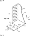
- FIGS. 1A and 2A to 2B show a first embodiment of a device 1 for fixing a frame according to the invention, the successive main steps of the method for fixing the frame using this device being illustrated schematically on figure 3 .
- the part of the wall delimiting the table around an opening in which the frame is installed is shown on this figure 3 without thermal insulation or any facing for better clarity of the figures.
- the figure3 only partially illustrates the fixing of a frame, several fixing devices being distributed around the periphery of the frame.
- the fixing device 1 comprises two separate elements joining together: a bracket 10 with two branches, and an adjustment bracket 11.
- Said bracket 10 comprises a first fixing branch 100 extending along the height of the square (direction Z) and a second adjustable branch 101 extending in the longitudinal direction X of the device, said branches thus being arranged substantially perpendicular to each other. . It also comprises a lateral reinforcing wall 102 extending between said two branches in the ZX plane.
- Said first fixing branch 100 comprises a set of fixing holes 1000 facilitating the taking of complementary fixing means, to allow the fixed frame to be fixed to it by surface or rebate using said complementary fixing means such as one or more. screw.
- said second branch 101 comprises a lateral part 1010 for fixing to the masonry and cooperating with the adjustment fixing bracket 11 to secure said two fixing elements together in an adjustable manner.
- Said lateral fixing part 1010 comprises an adjustment slot 1011 in the longitudinal direction of the device (X).
- This lateral fixing part 1010 also comprises a set of side reliefs 1012, projecting, arranged two by two symmetrically on each side of said adjustment slot 1011, forming means for maintaining and adjusting between said two fixing elements 10, 11 during the longitudinal adjustment of the device.
- Said adjustment fixing tab 11 of generally elongated shape extends in its main direction along the longitudinal direction X which defines the longitudinal direction of the device, its mean plane extending along the XY plane of the fixing device. It in fact comprises a central plate 110 pierced with a fixing hole 1101 surrounded by a rim 1102 appearing to project from the outer face of said plate, that is to say on the face opposite to the inner face which will be. directed towards the masonry in which the said bracket will be fixed.
- tab having a generally elongated shape is meant that the main direction of said fixing tab extends in its longitudinal direction.
- Said fixing lug 11 also comprises lateral holding and adjustment grooves 111 present transversely along the entire length of said strips 1111, 1112 which laterally border said plate, these said grooves forming a relief by alternating hollows and bumps on the inner face. strips, this face resting on the outer face of said lateral fixing part 1010 of the bracket 10 to cooperate with said reliefs 1012, when said lug and fixing bracket are assembled in a longitudinally adjustable manner to compose said fixing device , as illustrated by figure 1 .
- Said set of lateral retaining and adjusting reliefs 1012 of said lateral fixing part 1010 of the bracket 10 cooperates with said lateral grooves 111 of said fixing lug 11 to adjust the longitudinal position (X direction) of said fixing bracket 10 , in particular of its first branch 100 to which the frame will be fixed, so as to adapt the device to the thickness of the frame to be fixed, as will be explained in more detail in the comments of the figure 3 .
- These reliefs and grooves also make it possible by compression to correctly hold the two fastening elements 10, 11 together, preventing slipping, when their assembly is adjusted longitudinally and when they are joined together.
- Said respective means for maintaining and adjusting said elements cooperate with one another to enable the bracket to be moved longitudinally by guiding it and maintaining it in contact with the fixing lug.
- each strip 1111, 1112 is curved so that each curved end forms a support stop, the inner face of which will bear against the masonry, that is to say against one face of the table.
- the anchoring depth of the fixing device to the anchoring face of the wall, relative to the table is a predefined dimension, required for example by a regulation.
- the fixing tab is thus designed to serve as a template helping the installation of the device, the distance in the longitudinal direction X of the tab between a virtual axis passing through the central point of the exit orifice of said fixing hole 1101 of the tab and the inner face of each stop 1111, 1112 which said tab comprises being substantially equal to this required anchoring distance.
- the inner face of a stopper is defined as being the face of the stopper which will be turned towards the anchoring face of the wall, during the installation of said fixing device.
- a portion of each strip ending in a said stop 1111, 1112 is breakable in order to be able to remove this part of said tab after the installation of the frame.
- the thickness of said strips 1111, 1112 is adapted to the required thickness of weatherstripping (in the Z direction) to be reserved for a seal between the anchoring face of the wall and the frame.
- the figure 3 schematically shows the different steps of laying a frame D upright on a part of wall M, using said fixing device 1, without representation of the thermal insulation or of the possible facing for better clarity of the figure.
- the fixing lug 11 is used, alone as a template, by positioning it on the anchoring face M0 of the wall covered with a layer of insulation and a facing not shown in the figure.
- Said fixing lug 11 is arranged by placing the inner face of each stop 1111, 1112 formed by the curved end of each lateral strip resting against the adjacent face M1 of the switchboard, so that the center of the orifice emerging from the fixing hole 1101 is located on the anchoring face M0 at a given anchoring depth "d", for example a thickness required by regulations substantially equal to 60 mm, and the location in which the center of the fixing hole 1101 of said lug 11 by making a marking on said anchoring face M0 of the wall, for example using a pointed tool T, by passing this tool through the fixing hole 1101 of said lug 11 Then this fixing lug 11 is removed and an anchoring hole is drilled at the location of the mark in the masonry.
- said fixing bracket 10 is placed on said anchoring face M0 of the wall, the oblong fixing slot 1011 being at the level of said mark which has just been made, then said fixing lug 11 is placed on the lateral fixing part. 1010 of the square.
- a fixing screw V can be pegged then loosely screwed into the masonry by passing a dowel and this screw both through said fixing hole 1101 of said lug 11 and said oblong slot 1011 of said square to hold these two elements 10 , 11 together and in masonry.
- the longitudinal position (direction X) of said bracket 10 is adjusted by moving said bracket along the stroke allowed by said oblong slot 1011, so that the receiving face of the frame of said first branch 100 pierced with pre-fixing holes 1000 provided to fix the frame upright to it is positioned correctly longitudinally to receive this frame upright depending on the space available, taking into account the layer of insulation and the facing remained in place on the wall.
- said bracket is positioned in the right place, its fixing is finalized by tightening said screw V in the masonry.
- the fixed frame partially shown is positioned to the right of the masonry board in contact with the longitudinal strips 1111, 1112 in order to ensure the minimum thickness for the housing of the sealing gasket J for the caulking.
- the fixed frame is then fixed by its internal rebate to said first branch 100 of the bracket 10, using at least one screw V ', for example a self-drilling screw with a clipping groove, by inserting said screw V 'in a hole provided on the frame to screw it into one of the fixing holes 1000 of said branch 100.
- V ' for example a self-drilling screw with a clipping groove
- Said graduations carried on the strips 1111, 1112 of the fixing lug 11 of said fixing device 1 make it possible to adjust the position of the device in the longitudinal direction X, and more particularly that of the receiving branch 100 of the frame of the bracket 10 , and this similarly for the plurality of fixing devices 1 necessary for fixing one side of the frame, and more generally for all the fixing devices 1 distributed around the periphery of the frame, given the thickness of the frame. sleeping.
- Said device makes it possible to adjust the position of the fixing device to each situation, that is to say that the same fixing device is used for different poses of window frames for a given building, or different buildings to be renovated.
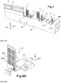
- FIGS. 4A to 4C show a second embodiment of a device for fixing a frame according to the invention, the successive main steps of the method for fixing the frame using this device being illustrated schematically on figure 5 .
- the part of the wall delimiting an opening in which the frame is installed is shown on the figure 5 without thermal insulation or possible facing for better clarity of the figure.
- the fixing device 2 comprises, as for the first embodiment, two separate elements joining together: an adjustable fixing bracket 20 with two branches, and a fixing bracket for setting 21.
- Said bracket 20 comprises a first branch 200 extending along the height of the square (direction Z), in the ZY plane, and a second branch 201 extending along the longitudinal direction X of the device, in the XY plane, said branches thus being arranged perpendicular to each other.
- Said bracket further comprises a lateral reinforcing wall 202 disposed between the two branches, in the XZ plane.
- Said first branch 200 comprises a set of fixing holes 2000 to enable said bracket to be fixed to the frame using complementary fixing means such as screws.
- Said second branch 201 comprises an adjustment recess 2010, of elongated shape in the longitudinal direction X of the device, emerging to form a notch in the bottom of the fixing branch 20, allowing assembly by fitting part of the tab. fixing 21.
- Said adjustment fixing bracket 21 comprises a fixing part pierced with a fixing hole 2100 to be fixed to the anchoring face of the wall and an adjustment part including a longitudinal strip 211.
- Said strip 211 comprises a stop 2112 in its free end, said stopper coming at the end of a breakable portion 2111 at the end of the strip, made breakable by a thinning of material and an initiation of rupture 21110.
- the stop allows the anchoring depth of the fixing device to the masonry to be at the same level as the first embodiment.
- said fixing lug serving as a template for fitting the device, the distance along the longitudinal direction X of the lug between a virtual axis passing through the central point of the lug fixing hole and the inner face of the stop that comprises said tab being equal to this required distance.
- Said strip bears graduations 2110 on its outer face, produced according to the example by different lateral notches with the mention of numbers, in millimeters according to the example, indicating different longitudinal adjustment positions of the fixing branch 200 of the square 20 useful when fixing the frame with said fixing device, as will be explained in more detail in the commentary on figure 5 .
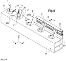
- the figure 5 shows schematically, in the left-right direction looking at the figure, the different main steps of fitting a frame upright D on a part of wall M, using said fixing device 2.
- the process is quite similar to that described in comments from the figure 3 .
- the fixing lug 21 is used, alone as a template, by positioning it on the anchoring face M0 of said part of the wall, to which said device will be fixed, covered with the insulation and the facing (not shown).
- Said fixing lug 21 is arranged in the insulation, in an area which has been hollowed out by removing a little insulation material, and so that the stop 2112 of the strip 211 is supported against the adjacent wall of the table M1 (wall substantially perpendicular to said wall anchoring face), and so that the fixing hole 2100 to the masonry is at the required anchoring depth (distance "d"), and the location of the anchoring hole to be made in the masonry by marking a mark on said anchoring face of the wall, for example using a pointed tool T, passing this tool through the fixing hole 2100 of said bracket 21 Alternatively, it is possible to drill directly, for example by passing the drill bit of a drill through said fixing hole 2100 of the tab that has remained in place.
- the fixing bracket 20 is positioned under said fixing lug 21 and so that said strip 211 fits into said recess 2010 open under said second branch 201 of the square, the longitudinal position (in the direction X) of said square being adjusted by means of the graduations 2110 of said strip 211 along which the part with the recess 2010 of said second longitudinal branch 201 of the square is moved.
- Said device 2 is fixed to the masonry by pegging and screwing a screw V through said fixing hole 2100 of the fixing bracket 21.
- the fixed frame partially shown is positioned to the right of the masonry board in contact with the longitudinal strip 211 in order to ensure the minimum thickness of weatherstripping required for the sealing gasket J.
- the location of the square behind the frame upright D is identified by means of the still visible stopper, and said frame is fixed to said device in at least one of said fixing pilot holes 2000 that comprises said first branch 200 of the 'square, for example by drilling the wall of the frame with at least one self-drilling screw V' and screwing said screw into one of said pilot holes 2000 of said first branch 200 of the square.
- a retaining wedge B included in a groove of the frame upright.
- the stop is removed by breaking the breakable portion at the end of the strip.
- FIGS. 6A to 6C show a third embodiment of a device 3 for fixing a frame according to the invention, said device comprising two separate elements joining together: a fixing bracket 30 with two branches, and an adjustment fixing bracket 31 .
- Said bracket 30 comprises a first branch 300 extending along the height of the square (direction Z), in the ZY plane, and a second branch 301 extending in the longitudinal direction X of the device, in the XY plane, said branches thus being arranged substantially perpendicular to each other.
- the bracket 30 further comprises a central reinforcing wall 302 disposed between the two branches, extending in the XZ plane.
- Said first branch 300 is flat with a lower corner cut out at a bevel, and comprises a set of 3,000 fixing holes to allow the frame to be fixed there using complementary fixing means such as screws.
- Said second branch 301 is generally cylindrical in shape, the main axial direction of which is oriented in the longitudinal direction X and allowing assembly by fitting and locking of the quarter-turn type with a part 312 of the fixing lug 31. It comprises on the surface holding and adjustment notches 3010, oriented transversely (direction Y) to the main axial direction of said cylinder.
- Said adjustment bracket 31 comprises an adjustment part and a lateral fixing block.
- Said lateral fixing block 310 comprises a fixing hole 3101 for fixing said fixing device 3 to the masonry.
- Said adjustment part comprises a hollow cylindrical body 3112 in which is inserted said second branch 301, of cylindrical shape, of the square, during the assembly of the two elements 30, 31, and said adjustment part including a strip longitudinal 311 (direction X) .
- Said strip 311 bears graduations 3110 on its outer face, identified according to the example by various transverse notches with the mention of figures, in millimeters according to the example, indicating depths of longitudinal adjustment of said device. fixing, and more particularly useful for the position of the fixing branch 300 of said bracket suitable for fixing the frame with said fixing device.
- Said strip 311 comprises a stop 3112 at its free end, said stop coming at the end of a breakable portion 3111 at the end of the strip.
- this stop makes it possible to use said fixing lug as a template in order to fix the fixing device to the masonry according to the required anchoring depth.
- the longitudinal position (direction X) of the fixing bracket more particularly the position of the fixing branch 300 in the longitudinal direction X for y fixing the frame, has been adjusted by translating said second branch 301 longitudinally in said hollow body 312 of the tab 31, by mark following the graduations of said strip 311.
- the fixing lug 31 serving as a template for locating the anchoring point of said device on the anchoring face of the masonry according to the required anchoring depth, and making the reservation for the trim d '' waterproofing according to the required caulking thickness.
- FIGS 7A to 7C show a fourth embodiment of a device 4 for fixing a frame according to the invention, said device comprising two separate fixing elements joining together: an adjustable bracket 40 with two branches, and an adjustment fixing bracket 41.
- Said bracket 40 comprises a first branch 400 extending along the height of the square (direction Z), in the ZY plane and a second branch 401 extending in the longitudinal direction, arranged substantially perpendicular to each other, as well as a central reinforcement wall 402 disposed between said two branches 400, 401, in the ZX plane, and lateral reinforcements 403, 404 between said two branches substantially in the XY plane.
- Said first frame fixing branch 400 is flat with a lower corner cut out at a bevel, and comprises a set of fixing holes 4000 to allow the frame to be fixed therein using complementary fixing means such as screws.
- Said second branch 401 is of generally semi-cylindrical shape, the main axis of which extends in the longitudinal direction X, hollowed out internally, and comprises on the internal surface retaining and adjustment notches 4010, oriented transversely to the main axial direction of said half cylinder.
- Said branch, or the half-cylinder comprises an open longitudinal base comprising two interior longitudinal projecting parts 4011, 4012, forming interior flanges oriented in the main axial direction of said half-cylinder.
- Said notches 4010 and said flanges 4011, 4012 allow the assembly of the bracket by fitting, of the quarter-turn type, with a part 412 of the fixing lug 41.
- Said adjustment fixing bracket 41 comprises a central fixing block 410, on either side of which extend longitudinally a first adjustment part 411 and a second adjustment part 412.
- Said fixing block 410 comprises a fixing hole 4101 to fix said tab, and thus said fixing device 4, to the anchoring face of the wall.
- Said first adjustment part is formed of a longitudinal strip 411 bearing marks in the form of graduations 4110 on its outer face, produced according to the example by different lateral notches with the mention of numbers, in millimeters according to the example, which will allow to adjust the longitudinal position of the square.
- Said strip 411 ends at its free end with an adjustment stop 4112. As explained for the embodiments described above, this stop allows said fixing lug to be used as a template in order to fix the fixing device to the face of.
- Said stopper 4112 comes at the end of a breakable longitudinal portion 4111 at the end of the strip, which can thus be detached.
- Said second adjustment part 412 comprises a partly cylindrical body having retaining and adjustment notches 4122 able to cooperate with said internal notches 4010 of said second branch 401 of the bracket 40.
- Said body further comprises a lateral slot 4120 in which is inserted the larger rim 4012 of said second branch 401 of the square, these elements forming locking and unlocking means of the fixing device of the quarter-turn type. It further comprises a lateral notch 4121 cooperating with the other rim 4011 of said second branch 401 of the bracket helping to retain the bracket on said tab, in particular during adjustments.
- the two fixing elements 40, 41 are assembled and secured to each other by fitting the semi-cylindrical branch 403 of the bracket 40 around said cylindrical body of said tab 41, and in a longitudinally adjustable manner (direction X), the internal notches 4010 of the longitudinal branch 401 of the square wedging in the notches 4122 of said tab. Thanks to the graduations 4110 on the strip 411, the longitudinal position for said first branch 400 of the square is identified, in order to adapt the device in particular to the thickness of the frame which will be fixed to the square.
- the locking and unlocking of the square to said tab in order to achieve the longitudinal adjustment of the square on said tab is effected by rotating said tab 40 by a quarter turn around the cylindrical body of said tab 41.
- the wall delimiting the receiving opening of the joinery to be installed comprises the masonry anchoring face M0 of the wall M, to which is fixed the joinery frame, generally of the so-called shell type, and at least one layer of thermal insulator C (and where appropriate also sound insulator), this layer itself being coated with a facing P such as for example a panel consisting of a plaster-based core.
- the fixing bracket 41 is used alone, as a template, so that the anchoring point of said fixing bracket to the anchoring face of the wall M0 is at the required anchoring depth "d" compared to the table (face M1).
- the adjustment fastening tab 41 is thus arranged in the insulating layer C, in an area which has been devoid of insulating material, and so that its stop 4112, on its inner face, rests against the adjacent wall. M1 of the table.
- An anchoring hole is drilled in the masonry, for example with a drill-driver S, by passing the bit mounted on the drill through the fixing hole 4101 of said bracket ( figure 8A ).
- Said fixing bracket 41 is then fixed by pegging the anchoring hole which has just been made in the masonry, then by screwing a screw therein through the fixing hole of said bracket. Then the fixing bracket 40 is secured to said fixing lug 41 by fitting said second branch 401 of said bracket 40 around the body in cylindrical part of said second adjustment part 412 of said fixing lug 41, as explained a little more up, by adjusting the longitudinal position (X direction) of said square 40 using graduations 4110 on the strip ( Fig. 8B ).
- a sealing gasket J can be applied in the space reserved according to the thickness of the longitudinal portion at the end of the strip.
- the frame D is then fixed by applying it to said first branch 400 of the bracket 40 which comprises the pre-drilled holes 4000, for example by introducing a self-drilling screw V 'from the exterior face of the frame and by reference thanks to said said frame. stopper 4112 still visible, in line with said stopper 4112 of said tab fixing 41 ( Fig. 8C ). Once the frame has been fitted, said breakable portion 4111 with said stopper 4112 is then removed.
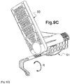
- FIGS 9A to 9D show another embodiment of a device for fixing a frame according to the invention, quite similar in its assembly to that described with reference to figures 7A to 7C .
- Said device 5 comprising two separate fixing elements joining together: an adjustable bracket 50 with two branches, and an adjustment fixing bracket 51.
- Said bracket 50 comprises a first branch 500 extending along the height of the square in the YZ plane, and a second branch 501 extending in the longitudinal direction X, arranged substantially perpendicular to each other, as well as a central wall of reinforcement 502 disposed in the ZX plane between said two branches 500, 501. It also comprises lateral reinforcements 504, 505, and other substantially horizontal lateral reinforcements 506, 507 extending in the XY plane between said wall 502 and the branch vertical 500.
- Said first branch 500 for fixing the frame is flat and comprises a set of fixing holes 5000 which make it possible to fix the frame therein using complementary fixing means such as screws.
- Said fixing holes are advantageously through holes of square shape, a shape well suited to receiving screws, in particular when fixing the frame which is done "blind” thanks to the identification of the device by the end of the tab.
- fixing 51 similar to what is explained above with reference to the figures 8A to 8C .
- Said second branch 501 of the square 50 is of semi-cylindrical general shape, the main axis of which extends in the longitudinal direction X. It is hollowed out internally, and comprises, on the upper internal surface, holding and adjustment notches 5010, oriented transversely to the main axial direction of said half-cylinder.
- Said branch, or the half-cylinder comprises an open longitudinal base comprising two internal projecting parts 5011, 5012, forming transverse internal edges and oriented longitudinally in the main axial direction of said half-cylinder.
- One of the ledges 5012 forms the large ledge because it is a little wider than the other and it ends with a return 50120 in a substantially vertical direction.
- Said notches 5010 and said flanges 5011, 5012 allow assembly of the square by fitting, of the quarter-turn type, with an adjustment part 512 of the fixing lug 51.
- Said adjustment fixing bracket 51 comprises a central fixing block 510, on either side of which extend longitudinally a first adjustment part 511 and a second adjustment part 512.
- Said fixing block 510 comprises a fixing hole 5101 to fix said tab to the wall, and therefore said fixing device 5 to the anchoring face of the wall.
- Said first adjustment part 511 comprises a longitudinal strip 5111 bearing marks 5110, in the form of graduations, on its upper outer face, produced according to the example with the mention of figures, in millimeters according to the example, which will allow adjustment of the longitudinal position of the square 51.
- Said first adjustment part 511 ends at its free end with an adjustment stop 5112. As explained for the embodiments described above, this stop 5112 allows said fixing tab 51 to be used as template in order to fix the fixing device 5 to the anchoring face of the masonry according to a given anchoring depth.
- Said stop 5112 comes at the end of said first adjustment part 511, then of the strip 5111 and of a curved portion 5114. According to the example, all of said first adjustment part 511 constitutes a breakable longitudinal portion of the device 5.
- Said curved portion 5114 which comprises said first part of adjustment 511, is located between the longitudinal strip 5111 and the stop 512, and has a curvature facing outwards and which extends beyond the level of the stop 5112.
- This curved portion 5114 when said fixing lug 51 or the entire device 5 are installed, allows to create a space between the wall and said adjustment part 511 which facilitates the gripping of said tab by an operator. The operator can pass one or more fingers through this space to grasp the end of said tab 51. This makes it possible to handle said tab more easily. tab, and to detach more easily the breakable part, or according to the example the adjustment part 511, at the end of the installation of the frame.
- Said second adjustment part 512 comprises a partly cylindrical body having holding and adjustment notches 5122 able to cooperate with said internal notches 5010 of said second branch 501 of the bracket 50.
- Said body further comprises a lateral slot 5120 in which is inserted the larger rim 5012 of said second branch 501 of the square, these elements forming locking and unlocking means of the fixing device of the quarter-turn type. It further comprises a lateral notch 5121 cooperating with the other rim 5011 of said second branch 501 of the square helping to retain the square on said tab, in particular during adjustments.
- the two fixing elements 50, 51 are assembled and secured to each other by fitting the semi-cylindrical branch 501 of the bracket 50 around said cylindrical body of said tab 51, and in an adjustable manner longitudinally (direction X) according to the arrow F, the internal notches 5010 of the longitudinal branch 501 of the bracket wedging in the notches 5122 of said tab. Thanks to the graduations 5110 on the strip 5111, the longitudinal position for said first branch 500 of the square is marked, in order to adapt the device in particular to the thickness of the frame which will be fixed to the square 50.
- the locking and unlocking of the square 50 to said tab 51 to achieve the attachment and the longitudinal adjustment of the square on said tab is done by rotating a quarter of a turn (arrow R) of said bracket 50 around of the cylindrical body of said tab 51.
- the strips or the longitudinal end portions bearing the abutment, the fixing lugs can advantageously be produced in a thickness making it possible to comply with a given thickness of caulking, or even required by a regulation, for a seal, between the edge of the frame and the bearing face (anchoring face M0) of the wall on which said edge rests.
- This minimum dimension required for the seal is for example 5 mm.
- the various elements of the fixing devices according to the invention which have just been described are advantageously made of plastic material having thermally insulating properties, which avoids introducing thermal bridges within the insulating layer around the joinery. renovation.
- This material can also comprise reinforcing elements such as, for example, glass fibers.
- the invention provides an economical fixing device for a joinery frame, in particular economical in labor, during the installation and fixing of the frame, in particular during a renovation by total removal, by facilitating the adjustment. from this installation to the presence of a layer of insulation and a possible facing, and also to the thickness of the frame to be fixed.
- Said device makes it possible to easily anchor the fixing device to the desired anchoring depth (in the longitudinal direction X) and to maintain there during the fixing of the frame, the position of the part of the device dedicated to the fixing of the frame. being further adjustable longitudinally from this anchoring position of the device fixing tab.
- the invention provides fixing devices adaptable to different wall configurations with insulation, once the fixing bracket is positioned at the required anchoring depth relative to the switchboard.
- the invention also makes it possible to provide a fixing device eliminating, or at the very least significantly reducing, the thermal bridges created by the fixing devices of the prior art.
Landscapes
- Engineering & Computer Science (AREA)
- Mechanical Engineering (AREA)
- Civil Engineering (AREA)
- Structural Engineering (AREA)
- Door And Window Frames Mounted To Openings (AREA)
- Connection Of Plates (AREA)
Applications Claiming Priority (1)
| Application Number | Priority Date | Filing Date | Title |
|---|---|---|---|
| FR2003216A FR3108650B1 (fr) | 2020-03-31 | 2020-03-31 | Dispositif de fixation d’un dormant de menuiserie |
Publications (2)
| Publication Number | Publication Date |
|---|---|
| EP3889383A1 true EP3889383A1 (de) | 2021-10-06 |
| EP3889383B1 EP3889383B1 (de) | 2023-08-09 |
Family
ID=71784189
Family Applications (1)
| Application Number | Title | Priority Date | Filing Date |
|---|---|---|---|
| EP21166242.4A Active EP3889383B1 (de) | 2020-03-31 | 2021-03-31 | Befestigungsvorrichtung eines fensterrahmens |
Country Status (6)
| Country | Link |
|---|---|
| EP (1) | EP3889383B1 (de) |
| ES (1) | ES2964008T3 (de) |
| FR (1) | FR3108650B1 (de) |
| MA (1) | MA56415B1 (de) |
| PL (1) | PL3889383T3 (de) |
| PT (1) | PT3889383T (de) |
Families Citing this family (1)
| Publication number | Priority date | Publication date | Assignee | Title |
|---|---|---|---|---|
| FR3140395B1 (fr) | 2022-09-30 | 2024-11-08 | Plasti Process | Dispositif de fixation d’un dormant d’une menuiserie comprenant des moyens de maintien et un moyen de manœuvre desdits moyens de maintien |
Citations (3)
| Publication number | Priority date | Publication date | Assignee | Title |
|---|---|---|---|---|
| FR2725263A1 (fr) * | 1994-10-04 | 1996-04-05 | Fuchs Dietrich Anton | Dispositif, notamment dispositif d'ancrage de distancement pour l'ajustage et la fixation de cadres |
| FR2966211A1 (fr) | 2010-10-15 | 2012-04-20 | Tordo Belgrano Sa | Equerre de fixation et mode de pose |
| FR2970284A1 (fr) | 2011-01-12 | 2012-07-13 | H L R | Patte et procede de fixation par vissage d'un dormant de menuiserie |
Family Cites Families (4)
| Publication number | Priority date | Publication date | Assignee | Title |
|---|---|---|---|---|
| WO2006075155A1 (en) * | 2005-01-13 | 2006-07-20 | Allmu A.S. | Method, device, connector and combination |
| KR200428810Y1 (ko) * | 2006-07-24 | 2006-10-13 | 한 기 김 | 창틀 고정용 브래키트 |
| KR200428811Y1 (ko) * | 2006-07-24 | 2006-10-13 | 한 기 김 | 창틀 고정용 브래키트 |
| GB0723283D0 (en) * | 2007-11-28 | 2008-01-09 | Sidey Ltd | Apparatus and method for installing windows and doors in timber frame cinstruction |
-
2020
- 2020-03-31 FR FR2003216A patent/FR3108650B1/fr not_active Expired - Fee Related
-
2021
- 2021-03-31 EP EP21166242.4A patent/EP3889383B1/de active Active
- 2021-03-31 PT PT211662424T patent/PT3889383T/pt unknown
- 2021-03-31 ES ES21166242T patent/ES2964008T3/es active Active
- 2021-03-31 MA MA56415A patent/MA56415B1/fr unknown
- 2021-03-31 PL PL21166242.4T patent/PL3889383T3/pl unknown
Patent Citations (3)
| Publication number | Priority date | Publication date | Assignee | Title |
|---|---|---|---|---|
| FR2725263A1 (fr) * | 1994-10-04 | 1996-04-05 | Fuchs Dietrich Anton | Dispositif, notamment dispositif d'ancrage de distancement pour l'ajustage et la fixation de cadres |
| FR2966211A1 (fr) | 2010-10-15 | 2012-04-20 | Tordo Belgrano Sa | Equerre de fixation et mode de pose |
| FR2970284A1 (fr) | 2011-01-12 | 2012-07-13 | H L R | Patte et procede de fixation par vissage d'un dormant de menuiserie |
Also Published As
| Publication number | Publication date |
|---|---|
| PL3889383T3 (pl) | 2024-01-29 |
| MA56415B1 (fr) | 2023-10-31 |
| FR3108650A1 (fr) | 2021-10-01 |
| EP3889383B1 (de) | 2023-08-09 |
| ES2964008T3 (es) | 2024-04-03 |
| MA56415A (fr) | 2022-05-04 |
| PT3889383T (pt) | 2023-10-19 |
| FR3108650B1 (fr) | 2022-06-10 |
Similar Documents
| Publication | Publication Date | Title |
|---|---|---|
| EP2906768B1 (de) | Anordnung mit mindestens zwei transversal oder endmontierbaren platten sowie ihre verwendung zur herstellung eines rahmens für eine tür oder ein fenster | |
| EP3889383B1 (de) | Befestigungsvorrichtung eines fensterrahmens | |
| EP1087075A1 (de) | Permanente Verankerungsvorrichtung | |
| EP3263813B1 (de) | Befestigungsvorrichtung eines beschlags in einem t-förmigen rahmenfalz | |
| WO2013093321A1 (fr) | Systeme permettant la fixation d'un objet sur un element a rainure(s) de fixation et dispositif de fixation pour un tel systeme | |
| WO2006123075A1 (fr) | Dispositif de fixation d'une ventouse ou d'une contrepiaque de serrure electromagnetique dans un profile | |
| FR2992017A1 (fr) | Coffre-tunnel incorporant une patte de fixation entre un linteau et le dormant d'une menuiserie | |
| EP3144447B1 (de) | Aufhängevorrichtung für paneele zur verkleidung eines gebäudes, und entsprechendes verfahren | |
| EP2159344A1 (de) | Bügel für die Befestigung einer Strebe auf einem Pfosten | |
| FR2966211A1 (fr) | Equerre de fixation et mode de pose | |
| EP4148221A1 (de) | Vorrichtung zur befestigung eines fensterrahmens mit einem monoblock-element | |
| EP3255224B1 (de) | Befestigungsvorrichtung eines geländers auf einer vorgefertigten mauer | |
| EP4345238B1 (de) | Vorrichtung zur befestigung eines blendrahmens einer türe mit haltemitteln und betätigungsmittel für diese halterung | |
| FR3100041A1 (fr) | Kit de fixation d’un système de doublage sur une structure à doubler | |
| FR2938286A1 (fr) | Gond reglable en position | |
| FR2967196A1 (fr) | Coffre de volet roulant comprenant des moyens de solidarisation de la traverse haute d'un element de menuiserie | |
| FR3032221A1 (fr) | Combinaison de profile parclose et de profile d'ouvrant en vue de la realisation de chassis d'ouvrant de fenetre et porte fenetre et procede de realisation d'ouvrants | |
| FR3113418A3 (fr) | Système de fixation d’un dormant de menuiserie et procédé de fixation d’un dormant l’utilisant | |
| FR3108930A1 (fr) | Coffre d’écran de protection, notamment un volet roulant, procédé d’assemblage associé et installation de protection comprenant un tel coffre | |
| FR2967443A1 (fr) | Huisserie pour porte ou fenetre composee de deux plaques de platre | |
| FR2515231A1 (de) | ||
| FR2753228A1 (fr) | Profil de jonction et de coupure thermique interpose entre des profiles aluminium utilises notamment dans la confection des cadres de fenetres ou de portes | |
| FR3162234A1 (fr) | Ensemble de structure réglable | |
| EP4055241A1 (de) | Schwellenvorrichtung, tischlerarbeit, die diese schwellenvorrichtung umfasst, und verfahren zum verwenden dieser schwellenvorrichtung | |
| EP4534781A1 (de) | Verriegelungsbeschlag-steuervorrichtung für tür- oder fensterrahmen |
Legal Events
| Date | Code | Title | Description |
|---|---|---|---|
| PUAI | Public reference made under article 153(3) epc to a published international application that has entered the european phase |
Free format text: ORIGINAL CODE: 0009012 |
|
| STAA | Information on the status of an ep patent application or granted ep patent |
Free format text: STATUS: THE APPLICATION HAS BEEN PUBLISHED |
|
| AK | Designated contracting states |
Kind code of ref document: A1 Designated state(s): AL AT BE BG CH CY CZ DE DK EE ES FI FR GB GR HR HU IE IS IT LI LT LU LV MC MK MT NL NO PL PT RO RS SE SI SK SM TR |
|
| STAA | Information on the status of an ep patent application or granted ep patent |
Free format text: STATUS: REQUEST FOR EXAMINATION WAS MADE |
|
| 17P | Request for examination filed |
Effective date: 20220329 |
|
| RAV | Requested validation state of the european patent: fee paid |
Extension state: MA Effective date: 20220329 |
|
| RBV | Designated contracting states (corrected) |
Designated state(s): AL AT BE BG CH CY CZ DE DK EE ES FI FR GB GR HR HU IE IS IT LI LT LU LV MC MK MT NL NO PL PT RO RS SE SI SK SM TR |
|
| GRAP | Despatch of communication of intention to grant a patent |
Free format text: ORIGINAL CODE: EPIDOSNIGR1 |
|
| STAA | Information on the status of an ep patent application or granted ep patent |
Free format text: STATUS: GRANT OF PATENT IS INTENDED |
|
| INTG | Intention to grant announced |
Effective date: 20220929 |
|
| GRAJ | Information related to disapproval of communication of intention to grant by the applicant or resumption of examination proceedings by the epo deleted |
Free format text: ORIGINAL CODE: EPIDOSDIGR1 |
|
| STAA | Information on the status of an ep patent application or granted ep patent |
Free format text: STATUS: REQUEST FOR EXAMINATION WAS MADE |
|
| GRAP | Despatch of communication of intention to grant a patent |
Free format text: ORIGINAL CODE: EPIDOSNIGR1 |
|
| STAA | Information on the status of an ep patent application or granted ep patent |
Free format text: STATUS: GRANT OF PATENT IS INTENDED |
|
| INTC | Intention to grant announced (deleted) | ||
| INTG | Intention to grant announced |
Effective date: 20230307 |
|
| GRAS | Grant fee paid |
Free format text: ORIGINAL CODE: EPIDOSNIGR3 |
|
| GRAA | (expected) grant |
Free format text: ORIGINAL CODE: 0009210 |
|
| STAA | Information on the status of an ep patent application or granted ep patent |
Free format text: STATUS: THE PATENT HAS BEEN GRANTED |
|
| AK | Designated contracting states |
Kind code of ref document: B1 Designated state(s): AL AT BE BG CH CY CZ DE DK EE ES FI FR GB GR HR HU IE IS IT LI LT LU LV MC MK MT NL NO PL PT RO RS SE SI SK SM TR |
|
| REG | Reference to a national code |
Ref country code: GB Ref legal event code: FG4D Free format text: NOT ENGLISH |
|
| REG | Reference to a national code |
Ref country code: CH Ref legal event code: EP |
|
| REG | Reference to a national code |
Ref country code: DE Ref legal event code: R096 Ref document number: 602021004071 Country of ref document: DE |
|
| REG | Reference to a national code |
Ref country code: IE Ref legal event code: FG4D Free format text: LANGUAGE OF EP DOCUMENT: FRENCH |
|
| REG | Reference to a national code |
Ref country code: PT Ref legal event code: SC4A Ref document number: 3889383 Country of ref document: PT Date of ref document: 20231019 Kind code of ref document: T Free format text: AVAILABILITY OF NATIONAL TRANSLATION Effective date: 20231013 |
|
| REG | Reference to a national code |
Ref country code: MA Ref legal event code: VAGR Ref document number: 56415 Country of ref document: MA Kind code of ref document: B1 |
|
| P01 | Opt-out of the competence of the unified patent court (upc) registered |
Effective date: 20231011 |
|
| REG | Reference to a national code |
Ref country code: LT Ref legal event code: MG9D |
|
| REG | Reference to a national code |
Ref country code: NL Ref legal event code: MP Effective date: 20230809 |
|
| REG | Reference to a national code |
Ref country code: AT Ref legal event code: MK05 Ref document number: 1597717 Country of ref document: AT Kind code of ref document: T Effective date: 20230809 |
|
| PG25 | Lapsed in a contracting state [announced via postgrant information from national office to epo] |
Ref country code: GR Free format text: LAPSE BECAUSE OF FAILURE TO SUBMIT A TRANSLATION OF THE DESCRIPTION OR TO PAY THE FEE WITHIN THE PRESCRIBED TIME-LIMIT Effective date: 20231110 |
|
| PG25 | Lapsed in a contracting state [announced via postgrant information from national office to epo] |
Ref country code: IS Free format text: LAPSE BECAUSE OF FAILURE TO SUBMIT A TRANSLATION OF THE DESCRIPTION OR TO PAY THE FEE WITHIN THE PRESCRIBED TIME-LIMIT Effective date: 20231209 |
|
| PG25 | Lapsed in a contracting state [announced via postgrant information from national office to epo] |
Ref country code: SE Free format text: LAPSE BECAUSE OF FAILURE TO SUBMIT A TRANSLATION OF THE DESCRIPTION OR TO PAY THE FEE WITHIN THE PRESCRIBED TIME-LIMIT Effective date: 20230809 Ref country code: RS Free format text: LAPSE BECAUSE OF FAILURE TO SUBMIT A TRANSLATION OF THE DESCRIPTION OR TO PAY THE FEE WITHIN THE PRESCRIBED TIME-LIMIT Effective date: 20230809 Ref country code: NO Free format text: LAPSE BECAUSE OF FAILURE TO SUBMIT A TRANSLATION OF THE DESCRIPTION OR TO PAY THE FEE WITHIN THE PRESCRIBED TIME-LIMIT Effective date: 20231109 Ref country code: NL Free format text: LAPSE BECAUSE OF FAILURE TO SUBMIT A TRANSLATION OF THE DESCRIPTION OR TO PAY THE FEE WITHIN THE PRESCRIBED TIME-LIMIT Effective date: 20230809 Ref country code: LV Free format text: LAPSE BECAUSE OF FAILURE TO SUBMIT A TRANSLATION OF THE DESCRIPTION OR TO PAY THE FEE WITHIN THE PRESCRIBED TIME-LIMIT Effective date: 20230809 Ref country code: LT Free format text: LAPSE BECAUSE OF FAILURE TO SUBMIT A TRANSLATION OF THE DESCRIPTION OR TO PAY THE FEE WITHIN THE PRESCRIBED TIME-LIMIT Effective date: 20230809 Ref country code: IS Free format text: LAPSE BECAUSE OF FAILURE TO SUBMIT A TRANSLATION OF THE DESCRIPTION OR TO PAY THE FEE WITHIN THE PRESCRIBED TIME-LIMIT Effective date: 20231209 Ref country code: HR Free format text: LAPSE BECAUSE OF FAILURE TO SUBMIT A TRANSLATION OF THE DESCRIPTION OR TO PAY THE FEE WITHIN THE PRESCRIBED TIME-LIMIT Effective date: 20230809 Ref country code: GR Free format text: LAPSE BECAUSE OF FAILURE TO SUBMIT A TRANSLATION OF THE DESCRIPTION OR TO PAY THE FEE WITHIN THE PRESCRIBED TIME-LIMIT Effective date: 20231110 Ref country code: FI Free format text: LAPSE BECAUSE OF FAILURE TO SUBMIT A TRANSLATION OF THE DESCRIPTION OR TO PAY THE FEE WITHIN THE PRESCRIBED TIME-LIMIT Effective date: 20230809 Ref country code: AT Free format text: LAPSE BECAUSE OF FAILURE TO SUBMIT A TRANSLATION OF THE DESCRIPTION OR TO PAY THE FEE WITHIN THE PRESCRIBED TIME-LIMIT Effective date: 20230809 |
|
| REG | Reference to a national code |
Ref country code: ES Ref legal event code: FG2A Ref document number: 2964008 Country of ref document: ES Kind code of ref document: T3 Effective date: 20240403 |
|
| PG25 | Lapsed in a contracting state [announced via postgrant information from national office to epo] |
Ref country code: SM Free format text: LAPSE BECAUSE OF FAILURE TO SUBMIT A TRANSLATION OF THE DESCRIPTION OR TO PAY THE FEE WITHIN THE PRESCRIBED TIME-LIMIT Effective date: 20230809 Ref country code: RO Free format text: LAPSE BECAUSE OF FAILURE TO SUBMIT A TRANSLATION OF THE DESCRIPTION OR TO PAY THE FEE WITHIN THE PRESCRIBED TIME-LIMIT Effective date: 20230809 Ref country code: EE Free format text: LAPSE BECAUSE OF FAILURE TO SUBMIT A TRANSLATION OF THE DESCRIPTION OR TO PAY THE FEE WITHIN THE PRESCRIBED TIME-LIMIT Effective date: 20230809 Ref country code: DK Free format text: LAPSE BECAUSE OF FAILURE TO SUBMIT A TRANSLATION OF THE DESCRIPTION OR TO PAY THE FEE WITHIN THE PRESCRIBED TIME-LIMIT Effective date: 20230809 Ref country code: CZ Free format text: LAPSE BECAUSE OF FAILURE TO SUBMIT A TRANSLATION OF THE DESCRIPTION OR TO PAY THE FEE WITHIN THE PRESCRIBED TIME-LIMIT Effective date: 20230809 Ref country code: SK Free format text: LAPSE BECAUSE OF FAILURE TO SUBMIT A TRANSLATION OF THE DESCRIPTION OR TO PAY THE FEE WITHIN THE PRESCRIBED TIME-LIMIT Effective date: 20230809 |
|
| REG | Reference to a national code |
Ref country code: DE Ref legal event code: R097 Ref document number: 602021004071 Country of ref document: DE |
|
| PLBE | No opposition filed within time limit |
Free format text: ORIGINAL CODE: 0009261 |
|
| STAA | Information on the status of an ep patent application or granted ep patent |
Free format text: STATUS: NO OPPOSITION FILED WITHIN TIME LIMIT |
|
| 26N | No opposition filed |
Effective date: 20240513 |
|
| PG25 | Lapsed in a contracting state [announced via postgrant information from national office to epo] |
Ref country code: SI Free format text: LAPSE BECAUSE OF FAILURE TO SUBMIT A TRANSLATION OF THE DESCRIPTION OR TO PAY THE FEE WITHIN THE PRESCRIBED TIME-LIMIT Effective date: 20230809 |
|
| PG25 | Lapsed in a contracting state [announced via postgrant information from national office to epo] |
Ref country code: BG Free format text: LAPSE BECAUSE OF FAILURE TO SUBMIT A TRANSLATION OF THE DESCRIPTION OR TO PAY THE FEE WITHIN THE PRESCRIBED TIME-LIMIT Effective date: 20230809 |
|
| PG25 | Lapsed in a contracting state [announced via postgrant information from national office to epo] |
Ref country code: LU Free format text: LAPSE BECAUSE OF NON-PAYMENT OF DUE FEES Effective date: 20240331 |
|
| PG25 | Lapsed in a contracting state [announced via postgrant information from national office to epo] |
Ref country code: MC Free format text: LAPSE BECAUSE OF FAILURE TO SUBMIT A TRANSLATION OF THE DESCRIPTION OR TO PAY THE FEE WITHIN THE PRESCRIBED TIME-LIMIT Effective date: 20230809 |
|
| PG25 | Lapsed in a contracting state [announced via postgrant information from national office to epo] |
Ref country code: MC Free format text: LAPSE BECAUSE OF FAILURE TO SUBMIT A TRANSLATION OF THE DESCRIPTION OR TO PAY THE FEE WITHIN THE PRESCRIBED TIME-LIMIT Effective date: 20230809 Ref country code: LU Free format text: LAPSE BECAUSE OF NON-PAYMENT OF DUE FEES Effective date: 20240331 Ref country code: BG Free format text: LAPSE BECAUSE OF FAILURE TO SUBMIT A TRANSLATION OF THE DESCRIPTION OR TO PAY THE FEE WITHIN THE PRESCRIBED TIME-LIMIT Effective date: 20230809 |
|
| PGFP | Annual fee paid to national office [announced via postgrant information from national office to epo] |
Ref country code: ES Payment date: 20250429 Year of fee payment: 5 |
|
| PGFP | Annual fee paid to national office [announced via postgrant information from national office to epo] |
Ref country code: CH Payment date: 20250401 Year of fee payment: 5 |
|
| PG25 | Lapsed in a contracting state [announced via postgrant information from national office to epo] |
Ref country code: CY Free format text: LAPSE BECAUSE OF FAILURE TO SUBMIT A TRANSLATION OF THE DESCRIPTION OR TO PAY THE FEE WITHIN THE PRESCRIBED TIME-LIMIT; INVALID AB INITIO Effective date: 20210331 |
|
| PG25 | Lapsed in a contracting state [announced via postgrant information from national office to epo] |
Ref country code: HU Free format text: LAPSE BECAUSE OF FAILURE TO SUBMIT A TRANSLATION OF THE DESCRIPTION OR TO PAY THE FEE WITHIN THE PRESCRIBED TIME-LIMIT; INVALID AB INITIO Effective date: 20210331 |
|
| VSFP | Annual fee paid to validation state [announced via postgrant information from national office to epo] |
Ref country code: MA Payment date: 20240228 Year of fee payment: 4 |
|
| VSFP | Annual fee paid to validation state [announced via postgrant information from national office to epo] |
Ref country code: MA Payment date: 20250328 Year of fee payment: 5 |
|
| PG25 | Lapsed in a contracting state [announced via postgrant information from national office to epo] |
Ref country code: TR Free format text: LAPSE BECAUSE OF FAILURE TO SUBMIT A TRANSLATION OF THE DESCRIPTION OR TO PAY THE FEE WITHIN THE PRESCRIBED TIME-LIMIT Effective date: 20230809 |
|
| REG | Reference to a national code |
Ref country code: CH Ref legal event code: U11 Free format text: ST27 STATUS EVENT CODE: U-0-0-U10-U11 (AS PROVIDED BY THE NATIONAL OFFICE) Effective date: 20260401 |
|
| PGFP | Annual fee paid to national office [announced via postgrant information from national office to epo] |
Ref country code: GB Payment date: 20260324 Year of fee payment: 6 |
|
| PGFP | Annual fee paid to national office [announced via postgrant information from national office to epo] |
Ref country code: IE Payment date: 20260319 Year of fee payment: 6 Ref country code: DE Payment date: 20260319 Year of fee payment: 6 |
|
| PGFP | Annual fee paid to national office [announced via postgrant information from national office to epo] |
Ref country code: BE Payment date: 20260319 Year of fee payment: 6 Ref country code: IT Payment date: 20260324 Year of fee payment: 6 |
|
| VSFP | Annual fee paid to validation state [announced via postgrant information from national office to epo] |
Ref country code: MA Payment date: 20260319 Year of fee payment: 6 |
|
| PGFP | Annual fee paid to national office [announced via postgrant information from national office to epo] |
Ref country code: FR Payment date: 20260330 Year of fee payment: 6 |
|
| PGFP | Annual fee paid to national office [announced via postgrant information from national office to epo] |
Ref country code: PT Payment date: 20260319 Year of fee payment: 6 |
|
| PGFP | Annual fee paid to national office [announced via postgrant information from national office to epo] |
Ref country code: PL Payment date: 20260319 Year of fee payment: 6 |