EP3890913B1 - Torche de soudage et procédé de fabrication correspondant - Google Patents
Torche de soudage et procédé de fabrication correspondant Download PDFInfo
- Publication number
- EP3890913B1 EP3890913B1 EP19828963.9A EP19828963A EP3890913B1 EP 3890913 B1 EP3890913 B1 EP 3890913B1 EP 19828963 A EP19828963 A EP 19828963A EP 3890913 B1 EP3890913 B1 EP 3890913B1
- Authority
- EP
- European Patent Office
- Prior art keywords
- welding torch
- electrode
- carrier
- wire
- head
- Prior art date
- Legal status (The legal status is an assumption and is not a legal conclusion. Google has not performed a legal analysis and makes no representation as to the accuracy of the status listed.)
- Active
Links
Images





Classifications
-
- B—PERFORMING OPERATIONS; TRANSPORTING
- B23—MACHINE TOOLS; METAL-WORKING NOT OTHERWISE PROVIDED FOR
- B23K—SOLDERING OR UNSOLDERING; WELDING; CLADDING OR PLATING BY SOLDERING OR WELDING; CUTTING BY APPLYING HEAT LOCALLY, e.g. FLAME CUTTING; WORKING BY LASER BEAM
- B23K9/00—Arc welding or cutting
- B23K9/02—Seam welding; Backing means; Inserts
- B23K9/028—Seam welding; Backing means; Inserts for curved planar seams
- B23K9/0282—Seam welding; Backing means; Inserts for curved planar seams for welding tube sections
- B23K9/0284—Seam welding; Backing means; Inserts for curved planar seams for welding tube sections with an electrode working inside the tube
-
- B—PERFORMING OPERATIONS; TRANSPORTING
- B22—CASTING; POWDER METALLURGY
- B22F—WORKING METALLIC POWDER; MANUFACTURE OF ARTICLES FROM METALLIC POWDER; MAKING METALLIC POWDER; APPARATUS OR DEVICES SPECIALLY ADAPTED FOR METALLIC POWDER
- B22F5/00—Manufacture of workpieces or articles from metallic powder characterised by the special shape of the product
- B22F5/10—Manufacture of workpieces or articles from metallic powder characterised by the special shape of the product of articles with cavities or holes, not otherwise provided for in the preceding subgroups
- B22F5/106—Tube or ring forms
-
- B—PERFORMING OPERATIONS; TRANSPORTING
- B23—MACHINE TOOLS; METAL-WORKING NOT OTHERWISE PROVIDED FOR
- B23K—SOLDERING OR UNSOLDERING; WELDING; CLADDING OR PLATING BY SOLDERING OR WELDING; CUTTING BY APPLYING HEAT LOCALLY, e.g. FLAME CUTTING; WORKING BY LASER BEAM
- B23K9/00—Arc welding or cutting
- B23K9/02—Seam welding; Backing means; Inserts
-
- B—PERFORMING OPERATIONS; TRANSPORTING
- B23—MACHINE TOOLS; METAL-WORKING NOT OTHERWISE PROVIDED FOR
- B23K—SOLDERING OR UNSOLDERING; WELDING; CLADDING OR PLATING BY SOLDERING OR WELDING; CUTTING BY APPLYING HEAT LOCALLY, e.g. FLAME CUTTING; WORKING BY LASER BEAM
- B23K9/00—Arc welding or cutting
- B23K9/16—Arc welding or cutting making use of shielding gas
- B23K9/167—Arc welding or cutting making use of shielding gas and of a non-consumable electrode
-
- B—PERFORMING OPERATIONS; TRANSPORTING
- B23—MACHINE TOOLS; METAL-WORKING NOT OTHERWISE PROVIDED FOR
- B23K—SOLDERING OR UNSOLDERING; WELDING; CLADDING OR PLATING BY SOLDERING OR WELDING; CUTTING BY APPLYING HEAT LOCALLY, e.g. FLAME CUTTING; WORKING BY LASER BEAM
- B23K9/00—Arc welding or cutting
- B23K9/16—Arc welding or cutting making use of shielding gas
- B23K9/173—Arc welding or cutting making use of shielding gas and of a consumable electrode
-
- B—PERFORMING OPERATIONS; TRANSPORTING
- B23—MACHINE TOOLS; METAL-WORKING NOT OTHERWISE PROVIDED FOR
- B23K—SOLDERING OR UNSOLDERING; WELDING; CLADDING OR PLATING BY SOLDERING OR WELDING; CUTTING BY APPLYING HEAT LOCALLY, e.g. FLAME CUTTING; WORKING BY LASER BEAM
- B23K9/00—Arc welding or cutting
- B23K9/24—Features related to electrodes
- B23K9/28—Supporting devices for electrodes
- B23K9/29—Supporting devices adapted for making use of shielding means
- B23K9/291—Supporting devices adapted for making use of shielding means the shielding means being a gas
- B23K9/296—Supporting devices adapted for making use of shielding means the shielding means being a gas using non-consumable electrodes
-
- B—PERFORMING OPERATIONS; TRANSPORTING
- B23—MACHINE TOOLS; METAL-WORKING NOT OTHERWISE PROVIDED FOR
- B23K—SOLDERING OR UNSOLDERING; WELDING; CLADDING OR PLATING BY SOLDERING OR WELDING; CUTTING BY APPLYING HEAT LOCALLY, e.g. FLAME CUTTING; WORKING BY LASER BEAM
- B23K9/00—Arc welding or cutting
- B23K9/32—Accessories
-
- B—PERFORMING OPERATIONS; TRANSPORTING
- B33—ADDITIVE MANUFACTURING TECHNOLOGY
- B33Y—ADDITIVE MANUFACTURING, i.e. MANUFACTURING OF THREE-DIMENSIONAL [3D] OBJECTS BY ADDITIVE DEPOSITION, ADDITIVE AGGLOMERATION OR ADDITIVE LAYERING, e.g. BY 3D PRINTING, STEREOLITHOGRAPHY OR SELECTIVE LASER SINTERING
- B33Y80/00—Products made by additive manufacturing
-
- B—PERFORMING OPERATIONS; TRANSPORTING
- B22—CASTING; POWDER METALLURGY
- B22F—WORKING METALLIC POWDER; MANUFACTURE OF ARTICLES FROM METALLIC POWDER; MAKING METALLIC POWDER; APPARATUS OR DEVICES SPECIALLY ADAPTED FOR METALLIC POWDER
- B22F2999/00—Aspects linked to processes or compositions used in powder metallurgy
-
- Y—GENERAL TAGGING OF NEW TECHNOLOGICAL DEVELOPMENTS; GENERAL TAGGING OF CROSS-SECTIONAL TECHNOLOGIES SPANNING OVER SEVERAL SECTIONS OF THE IPC; TECHNICAL SUBJECTS COVERED BY FORMER USPC CROSS-REFERENCE ART COLLECTIONS [XRACs] AND DIGESTS
- Y02—TECHNOLOGIES OR APPLICATIONS FOR MITIGATION OR ADAPTATION AGAINST CLIMATE CHANGE
- Y02P—CLIMATE CHANGE MITIGATION TECHNOLOGIES IN THE PRODUCTION OR PROCESSING OF GOODS
- Y02P10/00—Technologies related to metal processing
- Y02P10/25—Process efficiency
Definitions
- the present invention relates to welding torches, and in particular a welding torch, and a method of manufacturing such a welding torch according to the preamble of claims 1 and 11 (see for example WO 96/01717 A1 )
- Welding torches are manufactured in the classic way by assembling parts made of different materials (brass, stainless steel, copper, ceramic). These parts are obtained for example by machining. They are assembled by processes such as screwing, welding, brazing, etc.
- the body of the torch must integrate at least the functions of supplying electric current, shielding gas and passage of the metal wire. contribution, while being very compact.
- the passage of the electric current can be done through the material constituting the torch body, such that it is not necessary to provide a specific circuit for the passage of the current.
- the wire guide of the filler metal wire can thus be integrated into the welding head due to the presence of the insulating sheath. This contributes to the compactness of the torch.
- the invention relates to a method of manufacturing a welding torch having the above characteristics, the method comprising a manufacturing step during which the body is obtained by additive manufacturing in a metal conducting the electricity, see claim 11.
- the welding torch of the invention is typically intended for carrying out welding operations with filler metal, in areas where the available space is reduced or in areas inaccessible to operators.
- the welding torch is intended to be used in a gas-shielded arc welding process such as TIG, MIG, MAG, or any other suitable process.
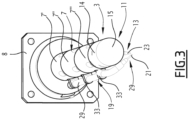
- the welding torch 1 shown on the figure 1 has a head 3.
- the head 3 has a cylindrical shape, of substantially circular section. It has a diameter of less than 50 mm, preferably less than 30 mm, more preferably less than 20 mm.
- It can have, for example, a diameter of 20 mm, so as to carry out welding operations inside a conduit with a diameter of less than 50 mm.
- the welding torch 1 also includes a carrier 7 secured to the head 3.
- the base 8 has, perpendicular to the axis of the conduit, a section much larger than the carrier or the head. It is designed to remain outside the conduit.
- the base 8 ensures the mechanical connection with the welding torch support. It carries the carrier 7 and other equipment or mechanisms such as fluid supplies (gas and coolant), electric current and filler wire.
- the carrier 7 is designed to be engaged in the conduit 5. It allows the welding head 3 to be placed in the working zone.
- the carrier 7 has the shape of an arm elongated along a central axis C.
- axis C is parallel to the central axis of conduit 5.
- the head 3 is located at an axial end of the carrier 7.
- the head 3 is located at the axial end of the carrier 7 opposite the base 8.
- the welding torch 1 preferably comprises a motorization 9 configured to rotate the head 3 relative to the conduit 5 around an axis of rotation, here corresponding to the central axis of the conduit 5.
- the motorization 9 is configured to rotate the head 3, the carrier 7 and the base 8.
- This motor controls the angular movement as well as the movement speed during welding.
- motors not shown allow the positioning of the torch 1 in part 5, axially and radially. These motors are for example used manually to position the head 3 as close as possible to the work area. In addition or alternatively, these motors are controlled automatically in order to ensure, for example, the regulation of the arc voltage during welding, or the oscillatory movements necessary for the welding operation.
- the central axis of the head 3 is not aligned with the central axis of the carrier 7.
- the central axis of the head 3 is aligned with the central axis of the carrier 7.
- the head 3 comprises a body 11 carrying an electrode 13 (case of implementing the TIG welding process).
- the body 11 has a generally cylindrical shape, with a cylindrical section 14 and an axial end 15 in the form of a sphere.
- the electrode 13 projects radially relative to the torch body 11.
- the torch 1 also includes a filler metal wire 17 and a wire guide 19 guiding the filler metal wire 17 to the electrode 13.
- the wire guide 19 guides the wire from a filler metal wire storage magazine (not shown) to the electrode 13. It is arranged so that the free end 21 of the wire is immediately next to the tip 23 of the electrode 13.
- the torch 1 also includes an electrical power supply 25, comprising an electrical current source 27.
- the body 11 is obtained by additive manufacturing in a metal conducting electricity.
- the electrode 13 is electrically connected to the electric current source 27 by the metal constituting the body 11 of the welding torch.
- the carrier 7 is also obtained by additive manufacturing in a metal conducting electricity.
- the electrode 13 is electrically connected to the electric current source 27 by the metal constituting the carrier 7 of the welding torch.
- the carrier 7 is for example made of several sections 7', 7", 7′′′ fixed to each other, three sections in the example shown.
- Each section 7', 7", 7′′′ defines an axial portion of the carrier.
- the sections 7', 7", 7′′′ are fixed axially in line with each other.
- Section 7' is mounted on base 8, and section 7' carries head 3. Section 7" connects sections 7' and 7'" to each other.
- the 7', 7", 7" sections are fixed to each other by any suitable means: screwing, welding, etc.
- the base 8 is also obtained by additive manufacturing in a metal conducting electricity.
- the electrode 13 is then electrically connected to the current source 27 by the metal constituting the base 8.
- the electric current is therefore not brought to the electrode 13 directly by a cable or an additional conductor.
- the electric current passes through the material constituting the elements obtained by additive manufacturing, typically the carrier 7, the torch body 11, and possibly the base 8.
- the elements obtained by additive manufacturing are electrically connected to the electric current source 27 by any suitable means, for example by cables not shown, arranged on the base of the welding torch.
- the metal conducting electricity is for example a steel, an aluminum alloy, a nickel alloy or a titanium alloy.
- the electrode 13 is typically made of tungsten (case of the TIG process) pure or doped with oxides (eg cerium, thorium, tantalum).
- the electrical potential of the current source can be transmitted directly to the filler wire in the case of the MIG or MAG process.
- the body 11 is obtained by any suitable additive manufacturing process (laser-powder, laser-wire, etc.).
- the carrier 7 and/or the base 8 are obtained, where appropriate, by the same process.
- the wire guide 19 advantageously comprises an insulating sheath 29, inside which the filler metal wire 17 moves ( Figure 4 ).
- the filler metal wire 17 is thus electrically isolated from the potential of the elements obtained by additive manufacturing, typically the carrier 7 and the body 11, by the insulating sheath 29.
- the insulating sheath 29 is made of a plastic material such as Teflon or any other suitable material.
- the insulating sheath 29 typically extends from the store to near the electrode 13.
- the filler metal wire 17 is free to slide inside the insulating sheath 29 towards the electrode 13.
- the wire is driven by a drive member not shown.
- the wire guide 19 is located entirely outside the head 3.
- the wire guide 19 comprises in this case for example a tube 31 located entirely outside the head 3.
- the tube 31 is also located entirely outside the carrier 7.
- This tube extends along the carrier 7, and along the head 3. It stops a short distance from the tip 23 of the electrode. It is attached to the carrier 7 by jumpers 33.
- the insulating sheath 29 and the filler metal wire 17 pass inside the tube 31.
- the tube 31 is for example made of steel.
- the torch 1 also includes a supply 35 of a shielding gas.
- the body 11 comprises an internal cavity 37 for passing the shielding gas, fluidly connected to the shielding gas supply 35.
- This cavity 37 is visible on the figures 5 to 7 .
- the internal cavity for passing the shielding gas 37 is arranged directly in the material of the body 11. It has any suitable shape, even complicated or tortuous. It is obtained in a simple and economical manner due to the fact that the body 11 is obtained by additive manufacturing.
- a protective gas supply port 39 is provided in the body 11 ( Figure 6 ). It opens into the internal cavity for passing the shielding gas 37, allowing its stabilization. It is connected to the protective gas supply 35 by any suitable means, for example by a conduit not shown crossing the entire length of the torch 1 from the base to the body 11, through the carrier 7.
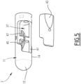
- the body 11 also includes an opening 41 for diffusing the shielding gas around the electrode 13, into which the internal cavity for the passage of the shielding gas 37 opens ( Figure 5 ).
- the opening 41 is for example formed in the cylindrical section 14.
- the electrode 13 passes through the diffusion opening 41.
- the head 3 preferably comprises a diffusion grid 43 extending into the diffusion opening 41 and obtained by additive manufacturing together with the body 11.
- the diffusion grid 43 therefore comes from one piece with the body 11. It constitutes a single piece with the body 11. On the figure 4 , it is shown separated from the body 11 only to reveal the internal structure of the head 3.
- the diffusion grid 43 is porous with respect to the shielding gas. It has passage holes for the shielding gas (not shown on the diagram). Figure 5 ), of suitable sizes and configuration. Preferably, these orifices constitute a three-dimensional mesh. The orifices are for example of rectangular section and are arranged in a rectangular pattern.
- the diffusion grid 43 occupies the entire surface of the diffusion opening 41.
- the body 11 forms a solid mass 45 located across the internal cavity for passing the shielding gas 37 ( figures 5 And 6 ).
- This mass 45 has an orifice 47 for receiving the electrode 13, in which the electrode 13 is blocked by any suitable means, for example by cooperation of shapes.
- This mass also constitutes a reinforcement and contributes to the rigidity of the body 11, to compensate for the weakening caused by the cavity 37 and the perforated structure of the diffusion grid 43.
- the welding head 1 includes a supply 49 of a cooling fluid ( figure 2 ).
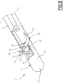
- the body 11 comprises an internal cavity 51 for passing the cooling fluid, fluidly connected to the cooling fluid supply 49 ( Figure 6 ).
- This refrigerant fluid circulates in a closed circuit through the torch from the base to the torch body 11, through the carrier 7.
- the body 11 comprises an external wall 53 internally delimiting the internal cavity for passing the shielding gas 37.
- the internal cavity for passing the cooling fluid 51 is formed in the thickness of the external wall 53.
- This internal cavity 51 has a complex shape. It typically comprises one or more axial sections such as section 54 of the Figure 6 , and one or more circumferential sections such as the sections 55 shown on the Figure 6 . These sections are arranged to cover the entire surface of the body 11. Its trajectory is thus substantially helical, which is made possible thanks to the unconventional manufacturing method.
- Cooling fluid inlet and outlet orifices 57, 59 are provided in the body 11 ( Figure 6 ).
- Sections 54 and 55 constitute a closed circuit fluidly connecting inlet 57 to outlet 59.
- the inlet 57 and the outlet 59 are connected to the cooling fluid supply 49 by any suitable means, for example conduits not shown passing through the carrier 7.
- the internal cavity for the passage of the cooling fluid 51 is thus formed directly in the material of the body 11. It is obtained in a simple and economical manner due to the fact that the body 11 is obtained by additive manufacturing.
- the torch 1 comprises a video observation system 61.
- the body 11 comprises an internal cavity 63 for passage of the video observation system 61.
- the video observation system 61 comprises for example an endoscope 65 extending into the internal cavity 63.
- the endoscope 65 preferably comprises an independent cooling system.
- the endoscope 65 has a diode 67 configured to ensure vision when the electric arc is extinguished.
- the diode 67 is carried by one end of the endoscope 65 curved to point towards the tip 23 of the electrode 13, through the orifice 41.
- the endoscope 65 extends over the entire length of the torch, from the base 8 to the head 3, inside the carrier 7.
- the image is in this case processed by an external camera, located at one end of the endoscope 65 opposite the diode 67.
- the image is sent to a monitor to allow an operator to control the head of the welding.
- the video observation system comprises a camera installed at the end of the torch body.
- a lighting device is then added nearby.
- a cable carrying the image signal extends into the internal cavity 63. It is connected at one end to the camera. It travels through the torch to its base 8, inside the carrier 7. The cable is connected to a monitor to allow an operator to control the welding head.
- the internal passage cavity of the video observation system 63 is formed in the thickness of the external wall 53.
- the torch 1 comprises at least one sensor 69 carried by the body 11 and a signal transmission cable 71 connected to the sensor 69 ( Figure 7 ).
- the body 11 has an internal cavity 73 for passing the signal transmission cable 71.
- the sensor 69 is for example an additional lamp, a temperature probe or any other type of sensor.
- the internal cavity for passing the signal transmission cable 73 is formed in the thickness of the external wall 53.
- the signal transmission cable 71 is configured to transmit the data acquired by the sensor 69 to remote equipment, for example a digital processing unit not shown.
- the signal transmission cable 71 leaving the internal cavity 73, runs through the carrier 7 then is connected to the remote equipment.
- the torch 1 comprises a light source carried by the body 11 and an electrical power cable connected to the light source.
- the body 11 then has an internal cavity for the passage of the electrical power cable.
- the light source is typically designed to visualize the working area of the torch 1.
- the internal cavity for passage of the electrical power cable is formed in the thickness of the external wall 53.
- the electrical power cable is configured to connect the light source to a source of electrical energy not shown.
- the body 11 has an internal cavity 75 through which the filler metal wire 17 and the insulating sheath 29 pass.
- the filler metal wire 17 circulates through the insulating sheath 29 facilitating its unwinding and insulating it from the electrical potential, from the base to the section 79.
- An external motor (not shown) drives it from a coil (not shown).
- the internal cavity 75 for passing the metal filler wire 17 comprises a section 77 formed in the thickness of the external wall 53. This section 77 is extended by a section 79 projecting from the external surface of the body and opening at the edge of the diffusion opening 41. The orientation of this section 79 defines the angle of arrival of the filler metal wire 17 in the weld pool.
- the wire guide 19 comprises a ceramic tip 81 fixed to the body 11 in the extension of the internal cavity 75. This tip is hollow, and defines an internal passage for the filler metal wire 17.
- the end piece 81 extends the section 79 over a short length towards the tip 23 of the electrode 13. It forms for example an angle of 45° with the electrode.
- the end piece 81 is for example fixed on the end of the section 79 in a removable manner, for example by screwing.
- the end piece 81 is in fact a wearing part, undergoing abrasion from the filler metal wire 17 in the same way as the sheath 29.
- the filler metal wire 17 emerging from the internal cavity 75 passes through the end piece 81 and emerges near the electrode 23, where it is consumed.
- the or each internal cavity 63, 73, 75 is thus formed directly in the material of the body 11. It is obtained in a simple and economical manner due to the fact that the body 11 is obtained by additive manufacturing.
- the invention also relates to a method of manufacturing a welding torch having the above characteristics.
- This process comprises a manufacturing step during which the body 11 is obtained by additive manufacturing in a metal conducting electricity.
- the manufacturing step also makes it possible to form the diffusion grid 43 jointly with the body 11.
- the method typically comprises a second manufacturing step during which the carrier 7 is obtained by additive manufacturing in a metal conducting electricity, and/or a third manufacturing step during which the base 8 is obtained by additive manufacturing in one metal that conducts electricity.
- the invention has multiple advantages.
- the invention makes it possible to produce welding torches of any geometry in the three dimensions (for example non-rectilinear and curved) with the aim of adapting to the actual configuration of the assembly to be produced and to the constraints of environment and available space.
- the three-dimensional printing manufacturing technique makes it possible to custom model, in a short time and at a lower cost, the equipment necessary for the welding operation according to the constraints of the application encountered, and the problems to be resolved.
- the welding torch comprises a head 3 fixed to the base 8 via a carrier 7.
- the head 3 is integral with the base 8. In d In other words, it is directly linked to the base 8, without the interposition of a carrier.
- the welding torch comprises in certain cases several elements obtained by additive manufacturing in a metal conducting electricity.
- at least the body 11 of the head is obtained by additive manufacturing.
- one or more segments of the carrier 7 and/or the base 8 are advantageously obtained by additive manufacturing.
- these different elements are obtained by additive manufacturing separately and then assembled together.
- these different elements are obtained together, by a single additive manufacturing operation leading to the formation of a single part.
Landscapes
- Engineering & Computer Science (AREA)
- Mechanical Engineering (AREA)
- Physics & Mathematics (AREA)
- Plasma & Fusion (AREA)
- Manufacturing & Machinery (AREA)
- Chemical & Material Sciences (AREA)
- Materials Engineering (AREA)
- Arc Welding In General (AREA)
Description
- La présente invention concerne les torches de soudage, et en particulier une torche de soudage, et un procédé de fabrication d'une telle torche de soudage selon le préambule des revendications 1 et 11 (voir par exemple
WO 96/01717 A1 - Les opérations de réparation par soudage dans l'industrie nucléaire, ou plus généralement sur des équipements lourds et des appareils à pression, imposent dans certains cas l'utilisation de torches de soudage de géométries complexes (non rectilignes). Ces torches doivent être miniaturisées pour permettre l'accès à la zone à réparer.
- Les torches de soudage sont fabriquées de manière classique par assemblage de pièces en des matériaux différents (laiton, acier inoxydable, cuivre, céramique). Ces pièces sont obtenues par exemple par usinage. Elles sont assemblées par des procédés tels que le vissage, le soudage, le brasage, etc.
- De tels procédés de fabrication sont onéreux.
- Les possibilités de miniaturisation sont limitées, notamment quand il est nécessaire d'intégrer de multiples fonctions : refroidissement, amenée de gaz de protection, instrumentation, vision déportée, etc.
- Dans ce contexte, l'invention vise à proposer une torche de soudage ne présentant pas les inconvénients ci-dessus. A cette fin, l'invention porte selon un premier aspect sur une torche de soudage telle que définie dans la revendication 1, comprenant
- une tête comportant un corps portant une électrode;
- une alimentation électrique, comportant une source de courant électrique;
- un fil de métal d'apport et un guide-fil guidant le fil de métal d'apport jusqu'à l'électrode; le corps étant obtenu par fabrication additive en un métal conduisant l'électricité, l'électrode étant raccordée électriquement à la source de courant électrique par le métal constituant le corps ;
- La fabrication de torche de soudage par fabrication additive, c'est-à-dire par impression en trois dimensions, permet d'obtenir des têtes de soudage de formes complexes, adaptées à chaque situation. Une telle fabrication est peu coûteuse.
- Dans le cas de la mise en oeuvre du procédé à arc électrique sous protection gazeuse avec métal d'apport, le corps de la torche doit intégrer au moins les fonctions amenée de courant électrique, de gaz de protection et de passage du fil de métal d'apport, tout en étant très compact. Notamment, le passage du courant électrique peut se faire au travers du matériau constituant le corps de torche, de telle sorte qu'il n'est pas nécessaire de prévoir un circuit spécifique pour le passage du courant.
- Le guide-fil du fil de métal d'apport peut ainsi être intégré à la tête de soudage du fait de la présence de la gaine isolante. Ceci contribue à la compacité de la torche.
- Il peut notamment faire saillie hors du corps de torche vers la pointe de l'électrode pour permettre l'arrivée du fil de métal d'apport à proximité de ladite pointe de l'électrode.
- La torche de soudage peut également présenter une ou plusieurs des caractéristiques ci-dessous, considérées individuellement ou selon toutes les combinaisons techniquement possibles :
- la torche de soudage comprend un porteur solidaire de la tête, le porteur étant obtenu par fabrication additive en un métal conduisant l'électricité, l'électrode étant raccordée électriquement à la source de courant électrique par le métal constituant le porteur, le fil de métal d'apport étant isolé électriquement du potentiel du porteur par la gaine isolante ;
- la torche de soudage comprend une embase obtenue par fabrication additive en un métal conduisant l'électricité, l'électrode étant raccordée électriquement à la source de courant électrique par le métal constituant l'embase, le porteur étant solidaire de l'embase;
- la torche de soudage comprend une embase obtenue par fabrication additive en un métal conduisant l'électricité, l'électrode étant raccordée électriquement à la source de courant électrique par le métal constituant l'embase, la tête étant solidaire de l'embase ;
- le corps comporte une cavité interne dans laquelle passent le fil de métal d'apport et la gaine isolante ;
- le guide-fil comprend un embout en céramique fixé au corps dans le prolongement de la cavité interne ;
- le guide-fil comprend un tube situé entièrement à l'extérieur de la tête, dans lequel passent le fil de métal d'apport et la gaine isolante ;
- le corps comporte une ouverture de diffusion du gaz de protection autour de l'électrode dans laquelle débouche la cavité interne de passage du gaz de protection, la tête comprenant une grille de diffusion s'étendant dans l'ouverture de diffusion et obtenue par fabrication additive conjointement avec le corps ;
- la torche comprend un système d'observation vidéo, le corps ayant une cavité interne de passage du système d'observation vidéo ;
- la torche comprend au moins un capteur porté par le corps et un câble de transmission du signal raccordé au capteur, le corps ayant une cavité interne de passage du câble de transmission du signal.
- Selon un second aspect, l'invention porte sur un procédé de fabrication d'une torche de soudage ayant les caractéristiques ci-dessus, le procédé comprenant une étape fabrication au cours de laquelle le corps est obtenu par fabrication additive en un métal conduisant l'électricité, voir la revendication 11.
- D'autres caractéristiques et avantages de l'invention ressortiront de la description détaillée qui en est donnée ci-dessous, à titre indicatif et nullement limitatif, en référence aux figures annexées, parmi lesquelles :
- [
Fig 1 ] lafigure 1 est une vue de côté d'une torche de soudage selon l'invention engagée dans un tube ; - [
Fig 2 ] [Fig 3 ] lesfigures 2 et3 sont des vues en perspectives, prises selon deux incidences différentes, d'une seconde torche de soudage selon l'invention ; - [
Fig 4 ] lafigure 4 est une vue en section de la gaine isolante et du fil de métal d'apport ; - [
Fig 5 ] lafigure 5 est une vue éclatée de la tête de la torche de soudage desfigures 2 et3 , montrant la cavité interne de passage du gaz de protection et la grille de diffusion du gaz de protection ; - [
Fig 6 ] lafigure 6 est une vue en coupe axiale de la tête de la torche desfigures 2 et3 , montrant la cavité interne de passage du fluide de refroidissement et la cavité interne de passage du gaz de protection ; - [
Fig 7 ] lafigure 7 est une vue en coupe axiale de la tête de la torche desfigures 2 et3 , similaire à celle de lafigure 5 , montrant les cavités internes de passage de l'instrumentation et la cavité interne de passage du gaz de protection ; et - [
Fig 8 ] lafigure 8 est une vue en perspective de la tête d'une troisième torche de soudage non couverte par la présente invention. - La torche de soudage de l'invention est destinée typiquement à la réalisation d'opération de soudage avec métal d'apport, dans des zones où l'espace disponible est réduit ou dans des zones inaccessibles pour des opérateurs.
- Elle est notamment destinée à la réalisation d'opérations de maintenance dans l'industrie nucléaire, par exemple une ou plusieurs des opérations énumérées ci-dessous :
- réparation d'une manchette de canne chauffante dans le pressuriseur d'un réacteur nucléaire à eau pressurisée (REP, ou PWR en anglais) ;
- remplacement d'un piquage de branche primaire ;
- toute intervention nécessitant une réparation dans un environnement inaccessible à l'homme, soit pour des raisons d'accessibilité soit pour des raisons radiologiques.
- En variante, elle est destinée à des interventions sur des équipements lourds et des appareils à pression, dans des installations nucléaires ou des installations industrielles non nucléaires.
- La torche de soudage est destinée à être utilisée dans un procédé de soudage à arc sous protection gazeuse de type TIG, MIG, MAG, ou tout autre procédé adapté.
- La torche de soudage 1 illustrée sur la
figure 1 , comporte une tête 3. - Celle-ci est de taille réduite, et peut être insérée dans des espaces réduits, ici l'intérieur d'un conduit 5.
- Typiquement, la tête 3 présente une forme cylindrique, de section sensiblement circulaire. Elle présente un diamètre inférieur à 50 mm, de préférence inférieur à 30 mm, encore de préférence, inférieur à 20 mm.
- Elle peut présenter par exemple un diamètre de 20mm, de manière à réaliser des opérations de soudage à l'intérieur d'un conduit de diamètre inférieur à 50 mm.
- La torche de soudage 1 comprend également un porteur 7 solidaire de la tête 3.
- Elle comporte généralement une embase 8, le porteur 7 étant solidaire de l'embase 8.
- L'embase 8 présente, perpendiculairement à l'axe du conduit, une section beaucoup plus grande que le porteur ou la tête. Elle est prévue pour rester à l'extérieur du conduit.
- L'embase 8 assure la liaison mécanique avec le support de la torche de soudage. Elle porte le porteur 7 et d'autres équipement ou mécanismes tels que les alimentations en fluide (gaz et liquide de refroidissement), en courant électrique et en fil d'apport.
- Le porteur 7 est prévu pour être engagé dans le conduit 5. Il permet de placer la tête de soudage 3 dans la zone de travail.
- Le porteur 7 présente la forme d'un bras allongé selon un axe central C.
- Sur la
figure 1 , l'axe C est parallèle à l'axe central du conduit 5. - La tête 3 est située à une extrémité axiale du porteur 7.
- La tête 3 est située à l'extrémité axiale du porteur 7 opposée à l'embase 8.
- La torche de soudage 1 comporte de préférence une motorisation 9 configurée pour faire tourner la tête 3 par rapport au conduit 5 autour d'un axe de rotation, correspondant ici à l'axe central du conduit 5.
- Plus précisément, la motorisation 9 est configurée pour faire tourner la tête 3, le porteur 7 et l'embase 8.
- Cette motorisation contrôle le déplacement angulaire ainsi que la vitesse de déplacement lors du soudage.
- D'autres motorisations non représentées permettent le positionnement de la torche 1 dans la pièce 5, axialement et radialement. Ces motorisations sont par exemple utilisées de manière manuelle pour positionner la tête 3 au plus près de la zone de travail. En plus ou alternativement, ces motorisations sont contrôlées de manière automatique afin d'assurer, par exemple, la régulation de la tension d'arc pendant le soudage, ou les mouvements oscillatoires nécessaires à l'opération de soudage.
- Dans l'exemple de la
figure 1 , l'axe central de la tête 3 n'est pas aligné avec l'axe central du porteur 7. - Dans l'exemple des
figures 2 et3 au contraire, l'axe central de la tête 3 est aligné avec l'axe central du porteur 7. - Sur les
figures 3 et8 , il apparaît que la tête 3 comporte un corps 11 portant une électrode 13 (cas de la mise en oeuvre du procédé de soudage TIG). - Le corps 11 présente une forme générale cylindrique, avec un tronçon cylindrique 14 et une extrémité axiale 15 en portion de sphère. L'électrode 13 fait saillie radialement par rapport au corps de torche 11.
- La torche 1 comporte encore un fil de métal d'apport 17 et un guide-fil 19 guidant le fil de métal d'apport 17 jusqu'à l'électrode 13.
- Le guide-fil 19 guide le fil depuis un magasin de stockage du fil en métal d'apport (non représenté) jusqu'à l'électrode 13. Il est agencé pour que l'extrémité libre 21 du fil se trouve immédiatement à côté de la pointe 23 de l'électrode 13.
- La torche 1 comprend encore une alimentation électrique 25, comportant une source de courant électrique 27.
- Avantageusement, le corps 11 est obtenu par fabrication additive en un métal conduisant l'électricité. L'électrode 13 est raccordée électriquement à la source de courant électrique 27 par le métal constituant le corps 11 de la torche de soudage.
- Typiquement, le porteur 7 est également obtenu par fabrication additive en un métal conduisant l'électricité.
- Dans ce cas, l'électrode 13 est raccordée électriquement à la source de courant électrique 27 par le métal constituant le porteur 7 de la torche de soudage.
- Le porteur 7 est par exemple réalisé en plusieurs tronçons 7', 7", 7‴ fixés les uns aux autres, trois tronçons dans l'exemple représenté.
- Chaque tronçon 7', 7", 7‴ définit une portion axiale du porteur. Les tronçons 7', 7", 7‴ sont fixés axialement les uns dans le prolongement des autres.
- Le tronçon 7' est monté sur l'embase 8, et le tronçon 7‴ porte la tête 3. Le tronçon 7" raccorde les tronçons 7' et 7'" l'un à l'autre.
- Les tronçons 7', 7", 7‴ sont fixés les uns aux autres par tous moyens adaptés : vissage, soudage, etc.
- Selon une variante avantageuse, l'embase 8 est également obtenue par fabrication additive en un métal conduisant l'électricité.
- L'électrode 13 est alors raccordée électriquement à la source de courant 27 par le métal constituant l'embase 8.
- Le courant électrique n'est donc pas amené à l'électrode 13 directement par un câble ou un conducteur annexe.
- Pour arriver à l'électrode 13, le courant électrique traverse le matériau constituant les éléments obtenus par fabrication additive, typiquement le porteur 7, le corps de torche 11, et éventuellement l'embase 8.
- Les éléments obtenus par fabrication additive sont raccordés électriquement à la source de courant électrique 27 par tous moyens adaptés, par exemple par des câbles non représentés, agencés sur l'embase de la torche de soudage.
- Le métal conduisant l'électricité est par exemple un acier, un alliage d'aluminium, un alliage de nickel ou un alliage de titane.
- L'électrode 13 est typiquement en tungstène (cas du procédé TIG) pur ou dopé d'oxydes (par ex. cérium, thorium, tantale).
- Le potentiel électrique de la source de courant peut être transmis directement au fil d'apport dans le cas de procédé MIG ou MAG.
- Le corps 11 est obtenu par tous procédé de fabrication additive adapté (laser-poudre, laser-fil,etc.).
- Le porteur 7 et/ou l'embase 8 sont obtenus, le cas échéant, par le même procédé.
- Le guide-fil 19 comprend avantageusement une gaine 29 isolante, à l'intérieur de laquelle le fil en métal d'apport 17 se déplace (
figure 4 ). Le fil de métal d'apport 17 est ainsi isolé électriquement du potentiel des éléments obtenus par fabrication additive, typiquement le porteur 7 et le corps 11, par la gaine isolante 29. - Par exemple, la gaine isolante 29 est en une matière plastique telle que le téflon ou toute autre matière adaptée.
- La gaine isolante 29 s'étend typiquement depuis le magasin jusqu'à proximité de l'électrode 13. Le fil de métal d'apport 17 est libre de coulisser à l'intérieur de la gaine isolante 29 vers l'électrode 13. Le fil est entraîné par un organe d'entraînement non représenté.
- Selon un mode de réalisation représenté sur les
figures 2 et3 , le guide-fil 19 est situé entièrement à l'extérieur de la tête 3. - Le guide-fil 19 comprend dans ce cas par exemple un tube 31 situé entièrement à l'extérieur de la tête 3.
- Le tube 31 est situé également entièrement à l'extérieur du porteur 7.
- Ce tube s'étend le long du porteur 7, et le long de la tête 3. Il s'arrête à courte distance de la pointe 23 de l'électrode. Il est fixé au porteur 7 par des cavaliers 33.
- La gaine isolante 29 et le fil de métal d'apport 17 passent à l'intérieur du tube 31. Le tube 31 est par exemple en acier.
- La torche 1 comprend également une alimentation 35 en un gaz de protection.
- Avantageusement, le corps 11 comprend une cavité interne 37 de passage du gaz de protection, raccordée fluidiquement à l'alimentation en gaz de protection 35. Cette cavité 37 est visible sur les
figures 5 à 7 . - La cavité interne de passage du gaz de protection 37 est aménagée directement dans la matière du corps 11. Elle présente toute forme adaptée, même compliquée ou tortueuse. Elle est obtenue de manière simple et économique du fait que le corps 11 est obtenu par fabrication additive.
- Un orifice 39 d'alimentation en gaz de protection est ménagé dans le corps 11 (
figure 6 ). Il débouche dans la cavité interne de passage du gaz de protection 37, permettant sa stabilisation. Il est raccordé à l'alimentation en gaz de protection 35 par tous moyens adaptés, par exemple par un conduit non représenté traversant toute la longueur de la torche 1 depuis l'embase jusqu'au corps 11, à travers le porteur 7. - Le corps 11 comporte également une ouverture 41 de diffusion du gaz de protection autour de l'électrode 13, dans laquelle débouche la cavité interne de passage du gaz de protection 37 (
figure 5 ). - L'ouverture 41 est par exemple ménagée dans le tronçon cylindrique 14. L'électrode 13 traverse l'ouverture de diffusion 41.
- La tête 3 comprend de préférence une grille de diffusion 43 s'étendant dans l'ouverture de diffusion 41 et obtenue par fabrication additive conjointement avec le corps 11.
- La grille de diffusion 43 est donc venue de matière avec le corps 11. Elle constitue une seule pièce avec le corps 11. Sur la
figure 4 , elle est représentée séparée du corps 11 seulement pour laisser apparaître la structure interne de la tête 3. - La grille de diffusion 43 est poreuse vis-à-vis du gaz de protection. Elle présente des orifices de passage pour le gaz de protection (non représentés sur la
figure 5 ), de tailles et de configuration adaptées. De préférence, ces orifices constituent un maillage tridimensionnel. Les orifices sont par exemple de section rectangulaire et sont disposés selon un motif rectangulaire. - La grille de diffusion 43 occupe toute la surface de l'ouverture de diffusion 41.
- Il est à noter que le corps 11 forme un massif 45 situé en travers de la cavité interne de passage du gaz de protection 37 (
figures 5 et6 ). Ce massif 45 présente un orifice 47 de réception de l'électrode 13, dans lequel l'électrode 13 est bloquée par tout moyen adapté, par exemple par coopération de formes. Ce massif constitue également un renfort et participe à la rigidité du corps 11, pour palier à l'affaiblissement occasionné par la cavité 37 et la structure ajourée de la grille de diffusion 43. - La tête de soudage 1 comprend une alimentation 49 en un fluide de refroidissement (
figure 2 ). Le corps 11 comprend une cavité interne 51 de passage du fluide de refroidissement, raccordée fluidiquement à l'alimentation en fluide de refroidissement 49 (figure 6 ). Ce fluide réfrigérant circule en circuit fermé au travers de la torche depuis l'embase jusqu'au corps 11 de torche, à travers le porteur 7. - Selon l'invention et comme montrée sur la
figure 6 , le corps 11 comprend une paroi externe 53 délimitant intérieurement la cavité interne de passage du gaz de protection 37. La cavité interne de passage du fluide de refroidissement 51 est ménagée dans l'épaisseur de la paroi externe 53. - Cette cavité interne 51 a une forme complexe. Elle comporte typiquement un ou plusieurs tronçons axiaux tels que le tronçon 54 de la
figure 6 , et un ou plusieurs tronçons circonférentiels tels que les tronçons 55 représentés sur lafigure 6 . Ces tronçons sont agencés pour parcourir toute la surface du corps 11. Sa trajectoire est ainsi sensiblement hélicoïdale, ce qui est rendu possible grâce au mode de fabrication non conventionnel. - Des orifices d'entrée et de sortie de fluide de refroidissement 57, 59 sont ménagés dans le corps 11 (
figure 6 ). - Les tronçons 54 et 55 constituent un circuit fermé raccordant fluidiquement l'entrée 57 à la sortie 59.
- L'entrée 57 et la sortie 59 sont raccordées à l'alimentation en fluide de refroidissement 49 par tous moyens adaptés, par exemple des conduits non représentés traversant le porteur 7.
- La cavité interne de passage du fluide de refroidissement 51 est ainsi ménagée directement dans la matière du corps 11. Elle est obtenue de manière simple et économique du fait que le corps 11 est obtenu par fabrication additive.
- Avantageusement, la torche 1 comprend un système d'observation vidéo 61. Le corps 11 comporte une cavité interne 63 de passage du système d'observation vidéo 61.
- Le système d'observation vidéo 61 comporte par exemple un endoscope 65 s'étendant dans la cavité interne 63. L'endoscope 65 comporte de préférence un système de refroidissement autonome.
- L'endoscope 65 embarque une diode 67 configurée pour assurer la vision lorsque l'arc électrique est éteint. La diode 67 est portée par une extrémité de l'endoscope 65 recourbée pour pointer vers la pointe 23 de l'électrode 13, à travers l'orifice 41.
- L'endoscope 65 s'étend sur toute la longueur de la torche, depuis l'embase 8 jusqu'à la tête 3, à l'intérieur du porteur 7.
- L'image est dans ce cas traitée par une caméra externe, située à une extrémité de l'endoscope 65 opposée à la diode 67. L'image est envoyée vers un moniteur pour permettre à un opérateur d'assurer le pilotage de la tête de soudage.
- Selon une autre variante, le système d'observation vidéo comporte une caméra installée en bout de corps de torche. Un dispositif d'éclairage est alors ajouté à proximité. Un câble transportant le signal de l'image s'étend dans la cavité interne 63. Il est raccordé par une extrémité à la caméra. Il parcourt la torche jusqu'à son embase 8, à l'intérieur du porteur 7. Le câble est raccordé à un moniteur pour permettre à un opérateur d'assurer le pilotage de la tête de soudage.
- La cavité interne de passage du système d'observation vidéo 63 est ménagée dans l'épaisseur de la paroi externe 53.
- De préférence, la torche 1 comprend au moins un capteur 69 porté par le corps 11 et un câble 71 de transmission du signal raccordé au capteur 69 (
figure 7 ). Le corps 11 présente une cavité interne 73 de passage du câble de transmission du signal 71. - Le capteur 69 est par exemple une lampe additionnelle, une sonde de température ou tout autre type de capteur.
- La cavité interne de passage du câble de transmission du signal 73 est ménagée dans l'épaisseur de la paroi externe 53.
- Le câble de transmission du signal 71 est configuré pour transmettre les données acquises par le capteur 69 à un équipement distant, par exemple une unité de traitement numérique non représentée.
- Le câble de transmission du signal 71, en sortant de la cavité interne 73, parcourt le porteur 7 puis est connecté à l'équipement distant.
- Selon une variante non représentée, la torche 1 comprend une source de lumière portée par le corps 11 et un câble d'alimentation électrique raccordé à la source de lumière. Le corps 11 présente alors une cavité interne de passage du câble d'alimentation électrique.
- La source de lumière est typiquement prévue pour visualiser la zone de travail de la torche 1.
- La cavité interne de passage du câble d'alimentation électrique est ménagée dans l'épaisseur de la paroi externe 53.
- Le câble d'alimentation électrique est configuré pour raccorder la source de lumière à une source d'énergie électrique non représentée. Le câble d'alimentation électrique, en sortant de la cavité interne, parcourt le porteur 7 puis est connecté à l'alimentation électrique.
- Selon la
figure 8 , le corps 11 comporte une cavité interne 75 dans laquelle passent le fil de métal d'apport 17 et la gaine isolante 29. - Comme précédemment, le fil de métal d'apport 17 circule à travers la gaine isolante 29 facilitant son dévidage et l'isolant du potentiel électrique, depuis l'embase jusqu'au tronçon 79. Un moteur externe (non représenté) l'entraine depuis une bobine (non représentée).
- La cavité interne 75 de passage du fil métal d'apport 17 comporte un tronçon 77 ménagé dans l'épaisseur de la paroi externe 53. Ce tronçon 77 est prolongé par un tronçon 79 faisant saillie sur la surface externe du corps et débouchant au bord de l'ouverture de diffusion 41. L'orientation de ce tronçon 79 définit l'angle d'arrivée du fil de métal d'apport 17 dans le bain de fusion.
- Le guide-fil 19 comprend un embout 81 en céramique fixé au corps 11 dans le prolongement de la cavité interne 75. Cet embout est creux, et définit un passage interne pour le fil de métal d'apport 17.
- L'embout 81 prolonge le tronçon 79 sur une courte longueur vers la pointe 23 de l'électrode 13. Il forme par exemple un angle de 45 ° avec l'électrode.
- L'embout 81 est par exemple fixé sur l'extrémité du tronçon 79 de manière amovible, par exemple par vissage. L'embout 81 est en effet une pièce d'usure, subissant l'abrasion du fil de métal d'apport 17 au même titre que la gaine 29.
- Le fil de métal d'apport 17 sortant de la cavité interne 75 traverse l'embout 81 et débouche à proximité de l'électrode 23, où il est consommé.
- La ou chaque cavité interne 63, 73, 75 est ainsi ménagée directement dans la matière du corps 11. Elle est obtenue de manière simple et économique du fait que le corps 11 est obtenu par fabrication additive.
- Les différentes pièces obtenues par fabrication additive (corps, tronçons, embase, etc.) ne nécessitent que très peu de reprises après impression. Dans la variante des
figures 2 et3 , il est nécessaire de réaliser les taraudages destinés à la fixation précise du tube 31. Il peut être également nécessaire de procéder au nettoyage et à la correction de planéïté des surfaces de liaison électrique entre l'embase 8, le porteur 7, le corps 11 et l'électrode 13. - L'invention porte aussi sur un procédé de fabrication d'une torche de soudage ayant les caractéristiques ci-dessus.
- Ce procédé comprend une étape fabrication au cours de laquelle le corps 11 est obtenu par fabrication additive en un métal conduisant l'électricité.
- Cette étape de fabrication permet avantageusement de former dans le corps 11 les cavités de la liste ci-dessous :
- cavité interne de passage du gaz de protection 37 ;
- cavité interne de passage du fluide de refroidissement 51 ;
- cavité interne de passage du système d'observation vidéo 61 le cas échéant ;
- cavité interne de passage du câble de transmission du signal 73 le cas échéant;
- cavité interne de passage du câble d'alimentation électrique raccordée à la source de lumière le cas échéant ;
- cavité interne 75 de passage de la gaine isolante et du fil de métal d'apport le cas échéant..
- De préférence, l'étape de fabrication permet également de former la grille de diffusion 43 conjointement avec le corps 11.
- Le procédé comporte typiquement une seconde étape fabrication au cours de laquelle le porteur 7 est obtenu par fabrication additive en un métal conduisant l'électricité, et/ou une troisième étape fabrication au cours de laquelle l'embase 8 est obtenue par fabrication additive en un métal conduisant l'électricité.
- L'invention présente de multiples avantages.
- Elle permet de réaliser des torches de soudage miniaturisées, par exemple d'un diamètre inférieur à 20 mm, dans lesquelles il est possible d'implémenter une ou plusieurs des fonctions suivantes : amenée du fil d'apport, amenée de la protection gazeuse, amenée de la vidéo, amenée de la puissance électrique, refroidissement de la torche et implantation de tout capteur de mesure nécessaire au contrôle du procédé de soudage.
- L'invention permet de réaliser des torches de soudage de géométrie quelconque dans les trois dimensions (à titre d'exemple non rectilignes et incurvées) dans le but de s'adapter à la configuration réelle de l'assemblage à réaliser et aux contraintes d'environnement et d'espace disponible.
- La technique de fabrication par impression tridimensionnelle permet de modeler à façon, dans un délai réduit et à moindre coût, le matériel nécessaire à l'opération de soudage en fonction des contraintes de l'application rencontrée, et des problématiques à résoudre.
- Dans les exemples de réalisation décrits ci-dessus, la torche de soudage comporte une tête 3 fixée à l'embase 8 par l'intermédiaire d'un porteur 7. En variante, la tête 3 est solidaire de l'embase 8. En d'autres termes, elle est directement liée à l'embase 8, sans interposition d'un porteur.
- Ainsi la torche de soudage comporte dans certains cas plusieurs éléments obtenus par fabrication additive en un métal conduisant l'électricité. Comme décrit ci-dessus, au moins le corps 11 de la tête est obtenu par fabrication additive. En plus, un ou plusieurs segments du porteur 7 et/ou l'embase 8 sont avantageusement obtenus par fabrication additive. Selon une variante, ces différents éléments sont obtenus par fabrication additive séparément puis assemblés les uns aux autres. Selon une autre variante, ces différents éléments sont obtenus ensemble, par une seule opération de fabrication additive conduisant à la formation d'une pièce unique. Ces différents éléments sont alors venus de matière.
Claims (11)
- Torche de soudage, la torche de soudage (1) comprenant :- une tête (3) comportant un corps (11) portant une électrode (13) ;- une alimentation électrique (25), comportant une source de courant électrique (27) ;- un fil de métal d'apport (17) et un guide-fil (19) guidant le fil de métal d'apport (17) jusqu'à l'électrode (13);et caractérisé par :le corps (11) étant obtenu par fabrication additive en un métal conduisant l'électricité, l'électrode (13) étant raccordée électriquement à la source de courant électrique (27) par le métal constituant le corps (11) le guide-fil (19) comprenant une gaine isolante (29) à l'intérieur de laquelle se déplace le fil de métal d'apport (17), le fil de métal d'apport (17) étant isolé électriquement du potentiel du corps (11) par la gaine isolante (29) ; dans laquelle la torche comprend une alimentation en un gaz de protection (35), le corps (11) comprenant une cavité interne de passage du gaz de protection (37) raccordée fluidiquement à l'alimentation en gaz de protection (35) ; eten ce que la torche (1) comprend une alimentation en un fluide de refroidissement (49), le corps (11) comprenant une cavité interne de passage du fluide de refroidissement (51) raccordée fluidiquement à l'alimentation en fluide de refroidissement (49) ; eten ce que le corps (11) comprend une paroi externe (53) délimitant intérieurement la cavité interne de passage du gaz de protection (37), la cavité interne de passage du fluide de refroidissement (51) étant ménagée dans l'épaisseur de la paroi externe (53).
- Torche de soudage selon la revendication 1, dans laquelle la torche de soudage (1) comprend un porteur (7) solidaire de la tête (3), le porteur (7) étant obtenu par fabrication additive en un métal conduisant l'électricité, l'électrode (13) étant raccordée électriquement à la source de courant électrique (27) par le métal constituant le porteur (7), le fil de métal d'apport (17) étant isolé électriquement du potentiel du porteur (7) par la gaine isolante (29)
- Torche de soudage selon la revendication 2, dans laquelle la torche de soudage (1) comprend une embase (8) obtenue par fabrication additive en un métal conduisant l'électricité, l'électrode (13) étant raccordée électriquement à la source de courant électrique (27) par le métal constituant l'embase (8), le porteur (7) étant solidaire de l'embase (8).
- Torche de soudage selon la revendication 1, dans laquelle la torche de soudage (1) comprend une embase (8) obtenue par fabrication additive en un métal conduisant l'électricité, l'électrode (13) étant raccordée électriquement à la source de courant électrique (27) par le métal constituant l'embase (8), la tête (3) étant solidaire de l'embase (8).
- Torche de soudage selon l'une quelconque des revendications précédentes, dans laquelle le corps (11) comporte une cavité interne (75) dans laquelle passent le fil de métal d'apport (17) et la gaine isolante (29).
- Torche de soudage selon la revendication 5, dans laquelle le guide-fil (19) comprend un embout (81) en céramique fixé au corps (11) dans le prolongement de la cavité interne (75).
- Torche de soudage selon l'une quelconque des revendications 1 à 4, dans laquelle le guide-fil (19) comprend un tube (31) situé entièrement à l'extérieur de la tête (3), dans lequel passent le fil de métal d'apport (17) et la gaine isolante (29).
- Torche de soudage selon l'une quelconque des revendications précédentes, dans laquelle le corps (11) comporte une ouverture de diffusion du gaz de protection (41) autour de l'électrode (13) dans laquelle débouche la cavité interne de passage du gaz de protection (37), la tête (3) comprenant une grille de diffusion (43) s'étendant dans l'ouverture de diffusion (41) et obtenue par fabrication additive conjointement avec le corps (11).
- Torche de soudage selon l'une quelconque des revendications précédentes, dans laquelle la torche (1) comprend un système d'observation vidéo (61), le corps (11) ayant une cavité interne de passage du système d'observation vidéo (63).
- Torche (1) de soudage selon l'une quelconque des revendications précédentes, dans laquelle la torche comprend au moins un capteur (69) porté par le corps (11) et un câble de transmission du signal (71) raccordé au capteur (69), le corps (11) ayant une cavité interne de passage du câble de transmission du signal (73).
- Procédé de fabrication d'une torche de soudage (1) selon l'une quelconque des revendications précédentes, le procédé comprenant une étape fabrication caractérisé en ce que le corps (11) est obtenu par fabrication additive en un métal conduisant l'électricité.
Applications Claiming Priority (2)
| Application Number | Priority Date | Filing Date | Title |
|---|---|---|---|
| FR1872355A FR3089444B1 (fr) | 2018-12-05 | 2018-12-05 | Torche de soudage et procédé de fabrication correspondant |
| PCT/EP2019/083472 WO2020115033A1 (fr) | 2018-12-05 | 2019-12-03 | Torche de soudage et procédé de fabrication correspondant |
Publications (2)
| Publication Number | Publication Date |
|---|---|
| EP3890913A1 EP3890913A1 (fr) | 2021-10-13 |
| EP3890913B1 true EP3890913B1 (fr) | 2023-10-11 |
Family
ID=66530153
Family Applications (1)
| Application Number | Title | Priority Date | Filing Date |
|---|---|---|---|
| EP19828963.9A Active EP3890913B1 (fr) | 2018-12-05 | 2019-12-03 | Torche de soudage et procédé de fabrication correspondant |
Country Status (6)
| Country | Link |
|---|---|
| US (1) | US12330245B2 (fr) |
| EP (1) | EP3890913B1 (fr) |
| ES (1) | ES2966081T3 (fr) |
| FI (1) | FI3890913T3 (fr) |
| FR (1) | FR3089444B1 (fr) |
| WO (1) | WO2020115033A1 (fr) |
Families Citing this family (2)
| Publication number | Priority date | Publication date | Assignee | Title |
|---|---|---|---|---|
| US20210268594A1 (en) * | 2020-02-27 | 2021-09-02 | The Esab Group Inc. | Dynamic torch head |
| CN112548279A (zh) * | 2020-11-27 | 2021-03-26 | 河北机电职业技术学院 | 一种可以单转或自转的调节型焊接装置 |
Family Cites Families (6)
| Publication number | Priority date | Publication date | Assignee | Title |
|---|---|---|---|---|
| US4532406A (en) * | 1984-02-10 | 1985-07-30 | General Electric Company | Arc welding torch having integrated wire feed |
| JPH0314074U (fr) * | 1989-06-26 | 1991-02-13 | ||
| WO1996001717A1 (fr) * | 1994-07-08 | 1996-01-25 | Cherne Larry W | Soudage a electrode de tungstene par fil d'apport froid, concentrique |
| US9833859B2 (en) * | 2014-09-15 | 2017-12-05 | Lincoln Global, Inc. | Electric arc torch with cooling conduit |
| US10898965B2 (en) * | 2016-09-17 | 2021-01-26 | Illinois Tool Works Inc. | Helical welding wire and helix forming welding torch |
| WO2018227189A1 (fr) * | 2017-06-09 | 2018-12-13 | Illinois Tool Works Inc. | Pointes de contact dotées de filets et d'une tête pour permettre le dévissage ou filets comprenant des fentes longitudinales destinées à un écoulement de gaz ; chalumeau de soudage doté de pointes de contact |
-
2018
- 2018-12-05 FR FR1872355A patent/FR3089444B1/fr active Active
-
2019
- 2019-12-03 ES ES19828963T patent/ES2966081T3/es active Active
- 2019-12-03 FI FIEP19828963.9T patent/FI3890913T3/fi active
- 2019-12-03 EP EP19828963.9A patent/EP3890913B1/fr active Active
- 2019-12-03 WO PCT/EP2019/083472 patent/WO2020115033A1/fr not_active Ceased
- 2019-12-03 US US17/299,159 patent/US12330245B2/en active Active
Also Published As
| Publication number | Publication date |
|---|---|
| WO2020115033A1 (fr) | 2020-06-11 |
| EP3890913A1 (fr) | 2021-10-13 |
| ES2966081T3 (es) | 2024-04-18 |
| US12330245B2 (en) | 2025-06-17 |
| FI3890913T3 (fi) | 2023-12-12 |
| FR3089444B1 (fr) | 2020-12-04 |
| US20220072643A1 (en) | 2022-03-10 |
| FR3089444A1 (fr) | 2020-06-12 |
Similar Documents
| Publication | Publication Date | Title |
|---|---|---|
| EP3890913B1 (fr) | Torche de soudage et procédé de fabrication correspondant | |
| JP6367186B2 (ja) | 紫色又は青色レーザーダイオードを用いた電気ケーブル剥皮装置 | |
| ES2961651T3 (es) | Máquina herramienta multieje, kit y método para conectar un primer cabezal de procesamiento a una máquina herramienta | |
| US5491317A (en) | System and method for laser welding an inner surface of a tubular member | |
| EP1459831B1 (fr) | Procédé de soudage TIG avec une torche de soudage TIG robotisé comprenant un ensemble buse/guide-fil | |
| US5563391A (en) | Orbital head laser welder | |
| EP0216694B1 (fr) | Dispositif de contrôle en temps réel d'un soudage à pénétration totale, adapté à un joint inaccessible à l'observation directe | |
| EP0923276A1 (fr) | Ensemble corps d'électrode/porte électrode pour torche plasma | |
| EP0609108A1 (fr) | Procédé et dispositif de soudage orbital d'une pièce cylindrique sur une paroi courbe | |
| WO2015097243A1 (fr) | Machine de soudure a arc electrique | |
| EP2556913B1 (fr) | Torche de soudage à l'arc à aspiration modulable des fumées | |
| FR2923295A1 (fr) | Procede et dispositif de visualisation et de controle du profil d'un cordon de soudure a l'interieur d'un chanfrein menage entre deux pieces metalliques | |
| EP0403327A1 (fr) | Procédé et dispositif de remplacement d'une canne chauffante d'un pressuriseur d'un réacteur nucléaire à eau sous pression | |
| CA2480569C (fr) | Ensemble buse/guide-fil pour torche de soudage tig robotise | |
| EP2561944B1 (fr) | Torche de soudage à l'arc à étanchéité améliorée | |
| EP0062554A1 (fr) | Ensemble mobile de soudage par points avec métal d'apport sous atmosphère gazeuse | |
| JPH0118829B2 (fr) | ||
| WO2005083718A2 (fr) | Dispositif de deplacement d'une barre de commande d'un reacteur nucleaire a eau sous pression et procede de montage du dispositif sur un couvercle de cuve | |
| CN110072662A (zh) | 焊枪和全姿势焊接装置 | |
| EP2292366B1 (fr) | Torche plasma à tête démontable avec bague à filetage trapézoïdal isocèle | |
| EP3556504B1 (fr) | Chalumeau soudeur et dispositif de soudage en toutes positions | |
| EP3623644A1 (fr) | Procede de fabrication d'un verin hydraulique et verin obtenu par ledit procede | |
| FR3132411A1 (fr) | Torche de coupage plasma munie d'un empilement de consommables | |
| JPS6150072B2 (fr) | ||
| WO2023143816A1 (fr) | Tuyère aval pour une torche de coupage plasma |
Legal Events
| Date | Code | Title | Description |
|---|---|---|---|
| STAA | Information on the status of an ep patent application or granted ep patent |
Free format text: STATUS: UNKNOWN |
|
| STAA | Information on the status of an ep patent application or granted ep patent |
Free format text: STATUS: THE INTERNATIONAL PUBLICATION HAS BEEN MADE |
|
| PUAI | Public reference made under article 153(3) epc to a published international application that has entered the european phase |
Free format text: ORIGINAL CODE: 0009012 |
|
| STAA | Information on the status of an ep patent application or granted ep patent |
Free format text: STATUS: REQUEST FOR EXAMINATION WAS MADE |
|
| 17P | Request for examination filed |
Effective date: 20210603 |
|
| AK | Designated contracting states |
Kind code of ref document: A1 Designated state(s): AL AT BE BG CH CY CZ DE DK EE ES FI FR GB GR HR HU IE IS IT LI LT LU LV MC MK MT NL NO PL PT RO RS SE SI SK SM TR |
|
| DAV | Request for validation of the european patent (deleted) | ||
| DAX | Request for extension of the european patent (deleted) | ||
| GRAP | Despatch of communication of intention to grant a patent |
Free format text: ORIGINAL CODE: EPIDOSNIGR1 |
|
| STAA | Information on the status of an ep patent application or granted ep patent |
Free format text: STATUS: GRANT OF PATENT IS INTENDED |
|
| INTG | Intention to grant announced |
Effective date: 20220829 |
|
| GRAJ | Information related to disapproval of communication of intention to grant by the applicant or resumption of examination proceedings by the epo deleted |
Free format text: ORIGINAL CODE: EPIDOSDIGR1 |
|
| STAA | Information on the status of an ep patent application or granted ep patent |
Free format text: STATUS: REQUEST FOR EXAMINATION WAS MADE |
|
| GRAP | Despatch of communication of intention to grant a patent |
Free format text: ORIGINAL CODE: EPIDOSNIGR1 |
|
| STAA | Information on the status of an ep patent application or granted ep patent |
Free format text: STATUS: GRANT OF PATENT IS INTENDED |
|
| INTC | Intention to grant announced (deleted) | ||
| INTG | Intention to grant announced |
Effective date: 20230510 |
|
| RIN1 | Information on inventor provided before grant (corrected) |
Inventor name: NICOLAS, HERVE Inventor name: PETIT, ALAIN Inventor name: RANC, MAXIMILIEN |
|
| P01 | Opt-out of the competence of the unified patent court (upc) registered |
Effective date: 20230606 |
|
| GRAS | Grant fee paid |
Free format text: ORIGINAL CODE: EPIDOSNIGR3 |
|
| GRAA | (expected) grant |
Free format text: ORIGINAL CODE: 0009210 |
|
| STAA | Information on the status of an ep patent application or granted ep patent |
Free format text: STATUS: THE PATENT HAS BEEN GRANTED |
|
| AK | Designated contracting states |
Kind code of ref document: B1 Designated state(s): AL AT BE BG CH CY CZ DE DK EE ES FI FR GB GR HR HU IE IS IT LI LT LU LV MC MK MT NL NO PL PT RO RS SE SI SK SM TR |
|
| REG | Reference to a national code |
Ref country code: GB Ref legal event code: FG4D Free format text: NOT ENGLISH |
|
| REG | Reference to a national code |
Ref country code: CH Ref legal event code: EP |
|
| REG | Reference to a national code |
Ref country code: DE Ref legal event code: R096 Ref document number: 602019039285 Country of ref document: DE |
|
| REG | Reference to a national code |
Ref country code: IE Ref legal event code: FG4D Free format text: LANGUAGE OF EP DOCUMENT: FRENCH |
|
| REG | Reference to a national code |
Ref country code: FI Ref legal event code: FGE |
|
| REG | Reference to a national code |
Ref country code: NL Ref legal event code: FP |
|
| REG | Reference to a national code |
Ref country code: SE Ref legal event code: TRGR |
|
| REG | Reference to a national code |
Ref country code: LT Ref legal event code: MG9D |
|
| REG | Reference to a national code |
Ref country code: AT Ref legal event code: MK05 Ref document number: 1619711 Country of ref document: AT Kind code of ref document: T Effective date: 20231011 |
|
| PG25 | Lapsed in a contracting state [announced via postgrant information from national office to epo] |
Ref country code: GR Free format text: LAPSE BECAUSE OF FAILURE TO SUBMIT A TRANSLATION OF THE DESCRIPTION OR TO PAY THE FEE WITHIN THE PRESCRIBED TIME-LIMIT Effective date: 20240112 |
|
| PG25 | Lapsed in a contracting state [announced via postgrant information from national office to epo] |
Ref country code: IS Free format text: LAPSE BECAUSE OF FAILURE TO SUBMIT A TRANSLATION OF THE DESCRIPTION OR TO PAY THE FEE WITHIN THE PRESCRIBED TIME-LIMIT Effective date: 20240211 |
|
| PG25 | Lapsed in a contracting state [announced via postgrant information from national office to epo] |
Ref country code: LT Free format text: LAPSE BECAUSE OF FAILURE TO SUBMIT A TRANSLATION OF THE DESCRIPTION OR TO PAY THE FEE WITHIN THE PRESCRIBED TIME-LIMIT Effective date: 20231011 |
|
| REG | Reference to a national code |
Ref country code: ES Ref legal event code: FG2A Ref document number: 2966081 Country of ref document: ES Kind code of ref document: T3 Effective date: 20240418 |
|
| PG25 | Lapsed in a contracting state [announced via postgrant information from national office to epo] |
Ref country code: AT Free format text: LAPSE BECAUSE OF FAILURE TO SUBMIT A TRANSLATION OF THE DESCRIPTION OR TO PAY THE FEE WITHIN THE PRESCRIBED TIME-LIMIT Effective date: 20231011 |
|
| PG25 | Lapsed in a contracting state [announced via postgrant information from national office to epo] |
Ref country code: LT Free format text: LAPSE BECAUSE OF FAILURE TO SUBMIT A TRANSLATION OF THE DESCRIPTION OR TO PAY THE FEE WITHIN THE PRESCRIBED TIME-LIMIT Effective date: 20231011 Ref country code: IS Free format text: LAPSE BECAUSE OF FAILURE TO SUBMIT A TRANSLATION OF THE DESCRIPTION OR TO PAY THE FEE WITHIN THE PRESCRIBED TIME-LIMIT Effective date: 20240211 Ref country code: GR Free format text: LAPSE BECAUSE OF FAILURE TO SUBMIT A TRANSLATION OF THE DESCRIPTION OR TO PAY THE FEE WITHIN THE PRESCRIBED TIME-LIMIT Effective date: 20240112 Ref country code: BG Free format text: LAPSE BECAUSE OF FAILURE TO SUBMIT A TRANSLATION OF THE DESCRIPTION OR TO PAY THE FEE WITHIN THE PRESCRIBED TIME-LIMIT Effective date: 20240111 Ref country code: AT Free format text: LAPSE BECAUSE OF FAILURE TO SUBMIT A TRANSLATION OF THE DESCRIPTION OR TO PAY THE FEE WITHIN THE PRESCRIBED TIME-LIMIT Effective date: 20231011 Ref country code: PT Free format text: LAPSE BECAUSE OF FAILURE TO SUBMIT A TRANSLATION OF THE DESCRIPTION OR TO PAY THE FEE WITHIN THE PRESCRIBED TIME-LIMIT Effective date: 20240212 |
|
| PG25 | Lapsed in a contracting state [announced via postgrant information from national office to epo] |
Ref country code: RS Free format text: LAPSE BECAUSE OF FAILURE TO SUBMIT A TRANSLATION OF THE DESCRIPTION OR TO PAY THE FEE WITHIN THE PRESCRIBED TIME-LIMIT Effective date: 20231011 Ref country code: PL Free format text: LAPSE BECAUSE OF FAILURE TO SUBMIT A TRANSLATION OF THE DESCRIPTION OR TO PAY THE FEE WITHIN THE PRESCRIBED TIME-LIMIT Effective date: 20231011 Ref country code: NO Free format text: LAPSE BECAUSE OF FAILURE TO SUBMIT A TRANSLATION OF THE DESCRIPTION OR TO PAY THE FEE WITHIN THE PRESCRIBED TIME-LIMIT Effective date: 20240111 Ref country code: LV Free format text: LAPSE BECAUSE OF FAILURE TO SUBMIT A TRANSLATION OF THE DESCRIPTION OR TO PAY THE FEE WITHIN THE PRESCRIBED TIME-LIMIT Effective date: 20231011 Ref country code: HR Free format text: LAPSE BECAUSE OF FAILURE TO SUBMIT A TRANSLATION OF THE DESCRIPTION OR TO PAY THE FEE WITHIN THE PRESCRIBED TIME-LIMIT Effective date: 20231011 |
|
| REG | Reference to a national code |
Ref country code: DE Ref legal event code: R119 Ref document number: 602019039285 Country of ref document: DE |
|
| PG25 | Lapsed in a contracting state [announced via postgrant information from national office to epo] |
Ref country code: DK Free format text: LAPSE BECAUSE OF FAILURE TO SUBMIT A TRANSLATION OF THE DESCRIPTION OR TO PAY THE FEE WITHIN THE PRESCRIBED TIME-LIMIT Effective date: 20231011 |
|
| PG25 | Lapsed in a contracting state [announced via postgrant information from national office to epo] |
Ref country code: CZ Free format text: LAPSE BECAUSE OF FAILURE TO SUBMIT A TRANSLATION OF THE DESCRIPTION OR TO PAY THE FEE WITHIN THE PRESCRIBED TIME-LIMIT Effective date: 20231011 |
|
| PG25 | Lapsed in a contracting state [announced via postgrant information from national office to epo] |
Ref country code: SK Free format text: LAPSE BECAUSE OF FAILURE TO SUBMIT A TRANSLATION OF THE DESCRIPTION OR TO PAY THE FEE WITHIN THE PRESCRIBED TIME-LIMIT Effective date: 20231011 |
|
| PG25 | Lapsed in a contracting state [announced via postgrant information from national office to epo] |
Ref country code: SM Free format text: LAPSE BECAUSE OF FAILURE TO SUBMIT A TRANSLATION OF THE DESCRIPTION OR TO PAY THE FEE WITHIN THE PRESCRIBED TIME-LIMIT Effective date: 20231011 Ref country code: SK Free format text: LAPSE BECAUSE OF FAILURE TO SUBMIT A TRANSLATION OF THE DESCRIPTION OR TO PAY THE FEE WITHIN THE PRESCRIBED TIME-LIMIT Effective date: 20231011 Ref country code: RO Free format text: LAPSE BECAUSE OF FAILURE TO SUBMIT A TRANSLATION OF THE DESCRIPTION OR TO PAY THE FEE WITHIN THE PRESCRIBED TIME-LIMIT Effective date: 20231011 Ref country code: IT Free format text: LAPSE BECAUSE OF FAILURE TO SUBMIT A TRANSLATION OF THE DESCRIPTION OR TO PAY THE FEE WITHIN THE PRESCRIBED TIME-LIMIT Effective date: 20231011 Ref country code: EE Free format text: LAPSE BECAUSE OF FAILURE TO SUBMIT A TRANSLATION OF THE DESCRIPTION OR TO PAY THE FEE WITHIN THE PRESCRIBED TIME-LIMIT Effective date: 20231011 Ref country code: DK Free format text: LAPSE BECAUSE OF FAILURE TO SUBMIT A TRANSLATION OF THE DESCRIPTION OR TO PAY THE FEE WITHIN THE PRESCRIBED TIME-LIMIT Effective date: 20231011 Ref country code: CZ Free format text: LAPSE BECAUSE OF FAILURE TO SUBMIT A TRANSLATION OF THE DESCRIPTION OR TO PAY THE FEE WITHIN THE PRESCRIBED TIME-LIMIT Effective date: 20231011 |
|
| PLBE | No opposition filed within time limit |
Free format text: ORIGINAL CODE: 0009261 |
|
| STAA | Information on the status of an ep patent application or granted ep patent |
Free format text: STATUS: NO OPPOSITION FILED WITHIN TIME LIMIT |
|
| PG25 | Lapsed in a contracting state [announced via postgrant information from national office to epo] |
Ref country code: LU Free format text: LAPSE BECAUSE OF NON-PAYMENT OF DUE FEES Effective date: 20231203 |
|
| PG25 | Lapsed in a contracting state [announced via postgrant information from national office to epo] |
Ref country code: MC Free format text: LAPSE BECAUSE OF FAILURE TO SUBMIT A TRANSLATION OF THE DESCRIPTION OR TO PAY THE FEE WITHIN THE PRESCRIBED TIME-LIMIT Effective date: 20231011 |
|
| PG25 | Lapsed in a contracting state [announced via postgrant information from national office to epo] |
Ref country code: MC Free format text: LAPSE BECAUSE OF FAILURE TO SUBMIT A TRANSLATION OF THE DESCRIPTION OR TO PAY THE FEE WITHIN THE PRESCRIBED TIME-LIMIT Effective date: 20231011 Ref country code: LU Free format text: LAPSE BECAUSE OF NON-PAYMENT OF DUE FEES Effective date: 20231203 |
|
| 26N | No opposition filed |
Effective date: 20240712 |
|
| REG | Reference to a national code |
Ref country code: IE Ref legal event code: MM4A |
|
| PG25 | Lapsed in a contracting state [announced via postgrant information from national office to epo] |
Ref country code: DE Free format text: LAPSE BECAUSE OF NON-PAYMENT OF DUE FEES Effective date: 20240702 Ref country code: IE Free format text: LAPSE BECAUSE OF NON-PAYMENT OF DUE FEES Effective date: 20231203 |
|
| PG25 | Lapsed in a contracting state [announced via postgrant information from national office to epo] |
Ref country code: SI Free format text: LAPSE BECAUSE OF FAILURE TO SUBMIT A TRANSLATION OF THE DESCRIPTION OR TO PAY THE FEE WITHIN THE PRESCRIBED TIME-LIMIT Effective date: 20231011 |
|
| PG25 | Lapsed in a contracting state [announced via postgrant information from national office to epo] |
Ref country code: SI Free format text: LAPSE BECAUSE OF FAILURE TO SUBMIT A TRANSLATION OF THE DESCRIPTION OR TO PAY THE FEE WITHIN THE PRESCRIBED TIME-LIMIT Effective date: 20231011 Ref country code: IE Free format text: LAPSE BECAUSE OF NON-PAYMENT OF DUE FEES Effective date: 20231203 Ref country code: DE Free format text: LAPSE BECAUSE OF NON-PAYMENT OF DUE FEES Effective date: 20240702 |
|
| PGFP | Annual fee paid to national office [announced via postgrant information from national office to epo] |
Ref country code: CH Payment date: 20250101 Year of fee payment: 6 |
|
| PG25 | Lapsed in a contracting state [announced via postgrant information from national office to epo] |
Ref country code: CY Free format text: LAPSE BECAUSE OF FAILURE TO SUBMIT A TRANSLATION OF THE DESCRIPTION OR TO PAY THE FEE WITHIN THE PRESCRIBED TIME-LIMIT; INVALID AB INITIO Effective date: 20191203 |
|
| PG25 | Lapsed in a contracting state [announced via postgrant information from national office to epo] |
Ref country code: HU Free format text: LAPSE BECAUSE OF FAILURE TO SUBMIT A TRANSLATION OF THE DESCRIPTION OR TO PAY THE FEE WITHIN THE PRESCRIBED TIME-LIMIT; INVALID AB INITIO Effective date: 20191203 |
|
| PG25 | Lapsed in a contracting state [announced via postgrant information from national office to epo] |
Ref country code: TR Free format text: LAPSE BECAUSE OF FAILURE TO SUBMIT A TRANSLATION OF THE DESCRIPTION OR TO PAY THE FEE WITHIN THE PRESCRIBED TIME-LIMIT Effective date: 20231011 |
|
| PGFP | Annual fee paid to national office [announced via postgrant information from national office to epo] |
Ref country code: NL Payment date: 20251127 Year of fee payment: 7 |
|
| REG | Reference to a national code |
Ref country code: CH Ref legal event code: U11 Free format text: ST27 STATUS EVENT CODE: U-0-0-U10-U11 (AS PROVIDED BY THE NATIONAL OFFICE) Effective date: 20260101 |
|
| REG | Reference to a national code |
Ref country code: CH Ref legal event code: R18 Free format text: ST27 STATUS EVENT CODE: U-0-0-R10-R18 (AS PROVIDED BY THE NATIONAL OFFICE) Effective date: 20260106 |
|
| PGFP | Annual fee paid to national office [announced via postgrant information from national office to epo] |
Ref country code: GB Payment date: 20251229 Year of fee payment: 7 |
|
| PGFP | Annual fee paid to national office [announced via postgrant information from national office to epo] |
Ref country code: FI Payment date: 20251124 Year of fee payment: 7 |
|
| PGFP | Annual fee paid to national office [announced via postgrant information from national office to epo] |
Ref country code: FR Payment date: 20251230 Year of fee payment: 7 |
|
| PGFP | Annual fee paid to national office [announced via postgrant information from national office to epo] |
Ref country code: BE Payment date: 20251226 Year of fee payment: 7 |
|
| PGFP | Annual fee paid to national office [announced via postgrant information from national office to epo] |
Ref country code: SE Payment date: 20251218 Year of fee payment: 7 |
|
| PGFP | Annual fee paid to national office [announced via postgrant information from national office to epo] |
Ref country code: ES Payment date: 20260112 Year of fee payment: 7 |