EP3892075B1 - Systèmes comprenant des outils agricoles connectés à des attelages de levage et systèmes et procédés de commande associés - Google Patents
Systèmes comprenant des outils agricoles connectés à des attelages de levage et systèmes et procédés de commande associés Download PDFInfo
- Publication number
- EP3892075B1 EP3892075B1 EP21157517.0A EP21157517A EP3892075B1 EP 3892075 B1 EP3892075 B1 EP 3892075B1 EP 21157517 A EP21157517 A EP 21157517A EP 3892075 B1 EP3892075 B1 EP 3892075B1
- Authority
- EP
- European Patent Office
- Prior art keywords
- relative
- lifting hitch
- sensor
- toolbar
- implement
- Prior art date
- Legal status (The legal status is an assumption and is not a legal conclusion. Google has not performed a legal analysis and makes no representation as to the accuracy of the status listed.)
- Active
Links
Images


Classifications
-
- A—HUMAN NECESSITIES
- A01—AGRICULTURE; FORESTRY; ANIMAL HUSBANDRY; HUNTING; TRAPPING; FISHING
- A01B—SOIL WORKING IN AGRICULTURE OR FORESTRY; PARTS, DETAILS, OR ACCESSORIES OF AGRICULTURAL MACHINES OR IMPLEMENTS, IN GENERAL
- A01B63/00—Lifting or adjusting devices or arrangements for agricultural machines or implements
-
- A—HUMAN NECESSITIES
- A01—AGRICULTURE; FORESTRY; ANIMAL HUSBANDRY; HUNTING; TRAPPING; FISHING
- A01B—SOIL WORKING IN AGRICULTURE OR FORESTRY; PARTS, DETAILS, OR ACCESSORIES OF AGRICULTURAL MACHINES OR IMPLEMENTS, IN GENERAL
- A01B63/00—Lifting or adjusting devices or arrangements for agricultural machines or implements
- A01B63/002—Devices for adjusting or regulating the position of tools or wheels
- A01B63/008—Vertical adjustment of tools
-
- A—HUMAN NECESSITIES
- A01—AGRICULTURE; FORESTRY; ANIMAL HUSBANDRY; HUNTING; TRAPPING; FISHING
- A01B—SOIL WORKING IN AGRICULTURE OR FORESTRY; PARTS, DETAILS, OR ACCESSORIES OF AGRICULTURAL MACHINES OR IMPLEMENTS, IN GENERAL
- A01B59/00—Devices specially adapted for connection between animals or tractors and agricultural machines or implements
- A01B59/04—Devices specially adapted for connection between animals or tractors and agricultural machines or implements for machines pulled or pushed by a tractor
- A01B59/042—Devices specially adapted for connection between animals or tractors and agricultural machines or implements for machines pulled or pushed by a tractor having pulling means arranged on the rear part of the tractor
- A01B59/043—Devices specially adapted for connection between animals or tractors and agricultural machines or implements for machines pulled or pushed by a tractor having pulling means arranged on the rear part of the tractor supported at three points, e.g. by quick-release couplings
-
- A—HUMAN NECESSITIES
- A01—AGRICULTURE; FORESTRY; ANIMAL HUSBANDRY; HUNTING; TRAPPING; FISHING
- A01B—SOIL WORKING IN AGRICULTURE OR FORESTRY; PARTS, DETAILS, OR ACCESSORIES OF AGRICULTURAL MACHINES OR IMPLEMENTS, IN GENERAL
- A01B59/00—Devices specially adapted for connection between animals or tractors and agricultural machines or implements
- A01B59/06—Devices specially adapted for connection between animals or tractors and agricultural machines or implements for machines mounted on tractors
- A01B59/066—Devices specially adapted for connection between animals or tractors and agricultural machines or implements for machines mounted on tractors of the type comprising at least two lower arms and one upper arm generally arranged in a triangle, e.g. three-point hitches
-
- A—HUMAN NECESSITIES
- A01—AGRICULTURE; FORESTRY; ANIMAL HUSBANDRY; HUNTING; TRAPPING; FISHING
- A01B—SOIL WORKING IN AGRICULTURE OR FORESTRY; PARTS, DETAILS, OR ACCESSORIES OF AGRICULTURAL MACHINES OR IMPLEMENTS, IN GENERAL
- A01B63/00—Lifting or adjusting devices or arrangements for agricultural machines or implements
- A01B63/02—Lifting or adjusting devices or arrangements for agricultural machines or implements for implements mounted on tractors
-
- A—HUMAN NECESSITIES
- A01—AGRICULTURE; FORESTRY; ANIMAL HUSBANDRY; HUNTING; TRAPPING; FISHING
- A01B—SOIL WORKING IN AGRICULTURE OR FORESTRY; PARTS, DETAILS, OR ACCESSORIES OF AGRICULTURAL MACHINES OR IMPLEMENTS, IN GENERAL
- A01B63/00—Lifting or adjusting devices or arrangements for agricultural machines or implements
- A01B63/02—Lifting or adjusting devices or arrangements for agricultural machines or implements for implements mounted on tractors
- A01B63/10—Lifting or adjusting devices or arrangements for agricultural machines or implements for implements mounted on tractors operated by hydraulic or pneumatic means
-
- A—HUMAN NECESSITIES
- A01—AGRICULTURE; FORESTRY; ANIMAL HUSBANDRY; HUNTING; TRAPPING; FISHING
- A01B—SOIL WORKING IN AGRICULTURE OR FORESTRY; PARTS, DETAILS, OR ACCESSORIES OF AGRICULTURAL MACHINES OR IMPLEMENTS, IN GENERAL
- A01B63/00—Lifting or adjusting devices or arrangements for agricultural machines or implements
- A01B63/02—Lifting or adjusting devices or arrangements for agricultural machines or implements for implements mounted on tractors
- A01B63/10—Lifting or adjusting devices or arrangements for agricultural machines or implements for implements mounted on tractors operated by hydraulic or pneumatic means
- A01B63/1006—Lifting or adjusting devices or arrangements for agricultural machines or implements for implements mounted on tractors operated by hydraulic or pneumatic means the hydraulic or pneumatic means structurally belonging to the tractor
-
- A—HUMAN NECESSITIES
- A01—AGRICULTURE; FORESTRY; ANIMAL HUSBANDRY; HUNTING; TRAPPING; FISHING
- A01B—SOIL WORKING IN AGRICULTURE OR FORESTRY; PARTS, DETAILS, OR ACCESSORIES OF AGRICULTURAL MACHINES OR IMPLEMENTS, IN GENERAL
- A01B63/00—Lifting or adjusting devices or arrangements for agricultural machines or implements
- A01B63/02—Lifting or adjusting devices or arrangements for agricultural machines or implements for implements mounted on tractors
- A01B63/10—Lifting or adjusting devices or arrangements for agricultural machines or implements for implements mounted on tractors operated by hydraulic or pneumatic means
- A01B63/111—Lifting or adjusting devices or arrangements for agricultural machines or implements for implements mounted on tractors operated by hydraulic or pneumatic means regulating working depth of implements
-
- A—HUMAN NECESSITIES
- A01—AGRICULTURE; FORESTRY; ANIMAL HUSBANDRY; HUNTING; TRAPPING; FISHING
- A01B—SOIL WORKING IN AGRICULTURE OR FORESTRY; PARTS, DETAILS, OR ACCESSORIES OF AGRICULTURAL MACHINES OR IMPLEMENTS, IN GENERAL
- A01B63/00—Lifting or adjusting devices or arrangements for agricultural machines or implements
- A01B63/02—Lifting or adjusting devices or arrangements for agricultural machines or implements for implements mounted on tractors
- A01B63/10—Lifting or adjusting devices or arrangements for agricultural machines or implements for implements mounted on tractors operated by hydraulic or pneumatic means
- A01B63/111—Lifting or adjusting devices or arrangements for agricultural machines or implements for implements mounted on tractors operated by hydraulic or pneumatic means regulating working depth of implements
- A01B63/1112—Lifting or adjusting devices or arrangements for agricultural machines or implements for implements mounted on tractors operated by hydraulic or pneumatic means regulating working depth of implements using a non-tactile ground distance measurement, e.g. using reflection of waves
-
- A—HUMAN NECESSITIES
- A01—AGRICULTURE; FORESTRY; ANIMAL HUSBANDRY; HUNTING; TRAPPING; FISHING
- A01B—SOIL WORKING IN AGRICULTURE OR FORESTRY; PARTS, DETAILS, OR ACCESSORIES OF AGRICULTURAL MACHINES OR IMPLEMENTS, IN GENERAL
- A01B63/00—Lifting or adjusting devices or arrangements for agricultural machines or implements
- A01B63/02—Lifting or adjusting devices or arrangements for agricultural machines or implements for implements mounted on tractors
- A01B63/10—Lifting or adjusting devices or arrangements for agricultural machines or implements for implements mounted on tractors operated by hydraulic or pneumatic means
- A01B63/111—Lifting or adjusting devices or arrangements for agricultural machines or implements for implements mounted on tractors operated by hydraulic or pneumatic means regulating working depth of implements
- A01B63/1115—Lifting or adjusting devices or arrangements for agricultural machines or implements for implements mounted on tractors operated by hydraulic or pneumatic means regulating working depth of implements using a mechanical ground contact sensor
-
- A—HUMAN NECESSITIES
- A01—AGRICULTURE; FORESTRY; ANIMAL HUSBANDRY; HUNTING; TRAPPING; FISHING
- A01B—SOIL WORKING IN AGRICULTURE OR FORESTRY; PARTS, DETAILS, OR ACCESSORIES OF AGRICULTURAL MACHINES OR IMPLEMENTS, IN GENERAL
- A01B63/00—Lifting or adjusting devices or arrangements for agricultural machines or implements
- A01B63/02—Lifting or adjusting devices or arrangements for agricultural machines or implements for implements mounted on tractors
- A01B63/10—Lifting or adjusting devices or arrangements for agricultural machines or implements for implements mounted on tractors operated by hydraulic or pneumatic means
- A01B63/118—Mounting implements on power-lift linkages
-
- A—HUMAN NECESSITIES
- A01—AGRICULTURE; FORESTRY; ANIMAL HUSBANDRY; HUNTING; TRAPPING; FISHING
- A01B—SOIL WORKING IN AGRICULTURE OR FORESTRY; PARTS, DETAILS, OR ACCESSORIES OF AGRICULTURAL MACHINES OR IMPLEMENTS, IN GENERAL
- A01B79/00—Methods for working soil
- A01B79/02—Methods for working soil combined with other agricultural processing, e.g. fertilising, planting
-
- A—HUMAN NECESSITIES
- A01—AGRICULTURE; FORESTRY; ANIMAL HUSBANDRY; HUNTING; TRAPPING; FISHING
- A01C—PLANTING; SOWING; FERTILISING
- A01C7/00—Sowing
- A01C7/20—Parts of seeders for conducting and depositing seed
- A01C7/201—Mounting of the seeding tools
- A01C7/203—Mounting of the seeding tools comprising depth regulation means
-
- A—HUMAN NECESSITIES
- A01—AGRICULTURE; FORESTRY; ANIMAL HUSBANDRY; HUNTING; TRAPPING; FISHING
- A01C—PLANTING; SOWING; FERTILISING
- A01C7/00—Sowing
- A01C7/20—Parts of seeders for conducting and depositing seed
- A01C7/208—Chassis; Coupling means to a tractor or the like; Lifting means; Side markers
-
- B—PERFORMING OPERATIONS; TRANSPORTING
- B60—VEHICLES IN GENERAL
- B60D—VEHICLE CONNECTIONS
- B60D1/00—Traction couplings; Hitches; Draw-gear; Towing devices
- B60D1/01—Traction couplings or hitches characterised by their type
- B60D1/02—Bolt or shackle-type couplings
-
- B—PERFORMING OPERATIONS; TRANSPORTING
- B60—VEHICLES IN GENERAL
- B60D—VEHICLE CONNECTIONS
- B60D1/00—Traction couplings; Hitches; Draw-gear; Towing devices
- B60D1/24—Traction couplings; Hitches; Draw-gear; Towing devices characterised by arrangements for particular functions
- B60D1/246—Traction couplings; Hitches; Draw-gear; Towing devices characterised by arrangements for particular functions for actuating the hitch by powered means
-
- B—PERFORMING OPERATIONS; TRANSPORTING
- B60—VEHICLES IN GENERAL
- B60D—VEHICLE CONNECTIONS
- B60D1/00—Traction couplings; Hitches; Draw-gear; Towing devices
- B60D1/24—Traction couplings; Hitches; Draw-gear; Towing devices characterised by arrangements for particular functions
- B60D1/42—Traction couplings; Hitches; Draw-gear; Towing devices characterised by arrangements for particular functions for being adjustable
- B60D1/46—Traction couplings; Hitches; Draw-gear; Towing devices characterised by arrangements for particular functions for being adjustable vertically
-
- G—PHYSICS
- G05—CONTROLLING; REGULATING
- G05D—SYSTEMS FOR CONTROLLING OR REGULATING NON-ELECTRIC VARIABLES
- G05D3/00—Control of position or direction
- G05D3/12—Control of position or direction using feedback
-
- A—HUMAN NECESSITIES
- A01—AGRICULTURE; FORESTRY; ANIMAL HUSBANDRY; HUNTING; TRAPPING; FISHING
- A01C—PLANTING; SOWING; FERTILISING
- A01C7/00—Sowing
- A01C7/08—Broadcast seeders; Seeders depositing seeds in rows
Definitions
- aspects of the present disclosure relate generally to machines and methods for working agricultural fields.
- aspects relate to implements (e.g., planters, tillage, etc.) and to methods of controlling such implements.
- Crop yields are affected by a variety of factors, such as seed placement, soil quality, weather, irrigation, and nutrient applications. Seeds are typically planted in trenches formed by discs or other mechanisms of a planter row unit. Depth of seed placement is important because seeds planted at different depths emerge at different times, resulting in uneven crop growth. Trench depth can be affected by soil type, moisture level, row unit speed, and operation of the opening discs. It would be beneficial to have improved methods of controlling the location of planter row units so that seeds can be more precisely placed in a field.
- US2017/359941 A1 discloses a system according to the preamble of claim 1.
- the terms “comprising,” “including,” “containing,” “characterized by,” and grammatical equivalents thereof are inclusive or open-ended terms that do not exclude additional, unrecited elements or method steps, but also include the more restrictive terms “consisting of” and “consisting essentially of” and grammatical equivalents thereof.
- the term "may” with respect to a material, structure, feature, or method act indicates that such is contemplated for use in implementation of an embodiment of the disclosure, and such term is used in preference to the more restrictive term “is” so as to avoid any implication that other, compatible materials, structures, features, and methods usable in combination therewith should or must be excluded.
- the term “configured” refers to a size, shape, material composition, and arrangement of one or more of at least one structure and at least one apparatus facilitating operation of one or more of the structure and the apparatus in a predetermined way.
- spatially relative terms such as “beneath,” “below,” “lower,” “bottom,” “above,” “upper,” “top,” “front,” “rear,” “left,” “right,” and the like, may be used for ease of description to describe one element's or feature's relationship to another element(s) or feature(s) as illustrated in the figures. Unless otherwise specified, the spatially relative terms are intended to encompass different orientations of the materials in addition to the orientation depicted in the figures.
- the term "substantially" in reference to a given parameter, property, or condition means and includes to a degree that one of ordinary skill in the art would understand that the given parameter, property, or condition is met with a degree of variance, such as within acceptable manufacturing tolerances.
- the parameter, property, or condition may be at least 90.0% met, at least 95.0% met, at least 99.0% met, or even at least 99.9% met.
- the term "about” used in reference to a given parameter is inclusive of the stated value and has the meaning dictated by the context (e.g., it includes the degree of error associated with measurement of the given parameter).
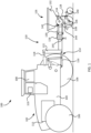
- FIG. 1 is a simplified side view of a system 100 including a tractor 102 and an implement 120.
- the tractor 102 includes a chassis 104 supported by wheels 106 and/or tracks.
- An operator cab 108 is typically supported by the chassis 104 and includes a control system 110 that may control operation of the tractor 102 and/or the implement 120.
- the operator cab 108 may be omitted if the tractor 102 is configured to function without an onboard human operator (e.g., as a remotely operated drone or a computer-operated machine).
- the control system 110 may include a central processing unit (“CPU”), memory, and graphical user interface ("GUI”) (e.g., a touch-screen interface).
- CPU central processing unit
- GUI graphical user interface
- a global positioning system (“GPS”) receiver may be mounted to the tractor 102 and connected to communicate with the control system 110.
- the tractor 102 has a power source 112 configured to move the wheels 106, which may include an internal combustion engine, an electric motor, or other source.
- the power source 112 may also provide power to a lifting hitch 114 carried by the tractor 102. Note that one of the rear wheels 106 has been omitted from view to more clearly show the lifting hitch 114.
- the lifting hitch 114 may be a 3-point hitch commonly carried by agricultural and other tractors.
- the lifting hitch 114 may be attached to the chassis 104 and include two lower lifting arms 116 to which the implement 120 may be attached.
- An additional top link 118 (depicted in FIG. 1 as a piston-type actuator) may connect the implement 120 to the tractor 102.
- the implement 120 has a frame 122 including an integrated toolbar 124 supporting row units 126. That is, the frame 122 and the toolbar 124 may form a rigid structure.
- the row units 126 may be any type of ground-engaging device for planting, seeding, fertilizing, tilling, or otherwise working crops or soil, typically in rows.
- the row unit 126 is shown in the form of a planter row unit.
- the row unit 126 has a body 128 pivotally connected to the toolbar 124 by a parallel linkage 130, enabling the row unit 126 to move vertically independent of the toolbar 124.
- the body 128 may be a unitary member, or may include one or more members coupled together (e.g., by bolts, welds, etc.).
- the body 128 operably supports one or more hoppers 132, a seed meter 134, a seed delivery mechanism 136, a seed trench opening assembly 138, a trench closing assembly 140, and any other components as known in the art.
- the row unit 126 shown in FIG. 1 may optionally be a part of a central fill planter, in which case the hoppers 132 may be one or more mini-hoppers fed by a central hopper carried by the implement 120.
- At least one sensor 142 and/or 144 is used to determine a position of a row unit 126 relative to the ground.
- the sensor(s) 142, 144 may be carried on the body 128 of the row unit 126 itself. In other embodiments, sensor(s) may be carried by the toolbar 124, the tractor 102, or even by another vehicle (e.g., another ground vehicle, an unmanned aerial vehicle, etc.).
- the sensor 142 may be a rotary sensor configured to measure an angle of an element of the parallel linkage 130 relative to the body 128 of the row unit 126 or to the toolbar 124, and may be connected to a pivot point of the body 128 of the row unit 126 or to the toolbar 124.
- an additional sensor 145 may be configured to detect the position of the toolbar 104 relative to the ground.
- the sensor(s) 144, 145 depicted may include a non-contact depth sensor, for example, an optical sensor, an ultrasonic transducer, an RF (radio frequency) sensor, lidar, radar, etc.
- a non-contact depth sensor for example, an optical sensor, an ultrasonic transducer, an RF (radio frequency) sensor, lidar, radar, etc.
- RF radio frequency
- the sensor(s) 142, 144, 145 provide information to the control system 110, which information can be used by the control system 110 to determine how to adjust the lifting hitch 114. That is, the control system 110 is configured to receive a signal (e.g., a wired or wireless signal) related to the position of the row unit 126 relative to the ground and cause the lifting hitch 114 to raise or lower a portion of the frame 122 connected to the lifting hitch 114 relative to the tractor 102 based at least in part on the signal.
- a signal e.g., a wired or wireless signal
- Movement of the lifting hitch 114 changes the position of the frame 122 and the toolbar 124 relative to the ground.
- the top link 118 may be used to change an angle of the frame 122 and the toolbar 124, and to control an orientation and position of the implement 120 relative to the tractor 102.
- the lifting hitch 114 may be used to raise or lower the toolbar 124 and independently change an angle of the toolbar 124 relative to the ground.
- the lifting hitch 114 may be configured such that upward movement of the lifting hitch 114 can cause upward movement of an entirety of the implement frame 122. Movement of the top link 118 separate from the lifting arms 116 may cause a change in the orientation of the frame 122.
- the sensor(s) 142, 144, 145 may provide a signal to the control system 110, and the control system 110 may use that signal to calculate how to change the position of the implement frame 122 to maintain a preselected position of the toolbar 124 and/or the row unit 126.
- the lifting hitch 114 may lower the implement frame 122 as the tractor 102 goes up a slope, and after the row unit 126 goes up the slope, the lifting hitch 114 may raise the implement frame 122 back to its prior position.
- the parallel linkages 130 of each row unit 126 may also adjust to move the row units 126 independent of one another. As depicted in FIG. 2 , movement of the lifting hitch 114 may be performed while maintaining a preselected orientation of the toolbar 124 by moving both the lifting arms 116 and the top link 118.
- the implement 120 may not have any tires coupled to the toolbar 124 for supporting the weight of the implement 120.
- the weight of the implement 120 may be supported by the lifting hitch 114.
- the row units 126 may include wheels in contact with the ground, such as in the seed trench opening assembly 138 or the trench closing assembly 140. Such wheels may support a portion of the weight of the implement 120.
- the implement 120 depicted lacks wheels or other ground support other than the row units 126.
- each row unit 126 may be adjusted independently of the other row units 126 by adjusting the individual parallel linkages 130.
- each parallel linkage 130 may be adjusted within its operating range such that each row unit 126 interacts with the ground at a preselected position. Movement of the toolbar 124 based on the lifting hitch 114 can increase the effective range of height of the row units 126 relative to the tractor 102.
- the implement 120 in combination with the tractor 102 as described may effectively be used to work fields having contours that are steeper than contours that can be effectively worked by conventional implements.
- FIG. 3 shows a simplified rear view of the implement 120 traveling over level ground.
- the lifting hitch 114 ( FIG. 1 ) is adjusted such that the row units 126 may each engage the ground by appropriate adjustment of the parallel linkages 130.
- the parallel linkages 130 may adjust the depth at which individual row units 126 operate (e.g., plant seeds) in the ground.
- FIG. 4 shows a simplified rear view of the implement 120 traveling over sloped ground, and illustrates how the implement 120 may adjust to different terrain.
- the ground at the left-hand side is sloped upward from the center, and the ground at the right-hand side is level.
- the toolbar 124 may be coupled to one or more adjustable wing sections 124a that can flex (i.e., move relative to the toolbar 124) to match different terrain, such as described in U.S. Patent 10,582,654, "Implement Load Balancing System," issued March 10, 2020 .
- One or more actuators 302 may raise or lower the wing section 124a such that the row units 126 carried by that wing section 124a remain at a preselected position with respect to the ground.
- the actuator 302 and the lifting hitch 114 may adjust the height and/or angle of the toolbar 124 or wing section(s) 124a, based at least in part on the sensed positions of the row units 126. Adjustment of the actuator 302 provides an additional range of adjustment beyond that provided by the parallel linkages 130 and the lifting hitch 114. That is, the row units 126 may be adjusted by moving the toolbar 124 upward or downward (i.e., by moving the lifting hitch 114), by moving the actuator 302, and by moving the row units 126 with respect to the toolbar 124 (i.e., by rotating the parallel linkage 130). Thus, each row unit 126 may exhibit a wider total range of motion than an implement 120 having only the parallel linkage 130 to adjust the height of the row unit 126 with respect to the tractor 102.
- the control system 110 may calculate an appropriate position of the actuator 302, the lifting hitch 114, and the parallel linkages 130 so that the row units 126 on the toolbar 124 and the wing section(s) 124a can each be at a preselected depth. That is, the control system 110 may select an actuator position and a hitch position such that the row units 126 can each be adjusted with the parallel linkages 130 to be at a preselected depth.
- the actuator 302 may enable a wider range of operating conditions (e.g., maximum field slope variation) than conventional wing control systems and may enable the control system 110 to respond more quickly to changing field terrain.
- implement 120 is described herein as a planter, other types of implements may have other types of row units, such as tillage implements (e.g., disc harrows, chisel plows, field cultivators, etc.) and seeding tools (e.g., grain drills, disc drills, etc.).
- tillage implements e.g., disc harrows, chisel plows, field cultivators, etc.
- seeding tools e.g., grain drills, disc drills, etc.
- FIG. 5 is a simplified flow chart illustrating a computer-implemented method 500 of using the implement 120 to work an agricultural field.
- an indication is received of a position of at least one row unit relative to ground sensed by a sensor.
- a signal from the sensor may be received by a controller.
- a lifting hitch raises or lowers an implement frame based at least in part on a sensed position of the at least one row unit.
- a signal may be sent to a control component associated with the tractor 102.
- the orientation of the toolbar may be maintained when the implement frame is raised or lowered.
- Still other embodiments involve a computer-readable storage medium (e.g., a non-transitory computer-readable storage medium) having processor-executable instructions configured to implement one or more of the techniques presented herein.
- a computer-readable storage medium e.g., a non-transitory computer-readable storage medium
- FIG. 6 An example computer-readable medium that may be devised is illustrated in FIG. 6 , wherein an implementation 600 includes a computer-readable storage medium 602 (e.g., a flash drive, CD-R, DVD-R, application-specific integrated circuit (ASIC), field-programmable gate array (FPGA), a platter of a hard disk drive, etc.), on which is computer-readable data 604.
- This computer-readable data 604 in turn includes a set of processor-executable instructions 606 configured to operate according to one or more of the principles set forth herein.
- the processor-executable instructions 606 may be configured to cause a computer associated with the tractor 102 ( FIG. 1 ) to perform operations 608 when executed via a processing unit, such as at least some of the example method 500 depicted in FIG. 5 .
- the processor-executable instructions 606 may be configured to control a system, such as at least some of the example system 100 depicted in FIG. 1 .
- Many such computer-readable media may be devised by those of ordinary skill in the art that are configured to operate in accordance with one or more of the techniques presented herein.
Landscapes
- Life Sciences & Earth Sciences (AREA)
- Engineering & Computer Science (AREA)
- Mechanical Engineering (AREA)
- Soil Sciences (AREA)
- Environmental Sciences (AREA)
- Transportation (AREA)
- Zoology (AREA)
- Physics & Mathematics (AREA)
- General Physics & Mathematics (AREA)
- Automation & Control Theory (AREA)
- Agricultural Machines (AREA)
- Lifting Devices For Agricultural Implements (AREA)
Claims (14)
- Dispositif (100), comprenant :un tracteur (102) comprenant un attelage de levage (114) ;un outillage (120) comprenant un châssis d'outillage (122) supporté par l'attelage de levage,caractérisé par le fait que bâti d'outillage comporte une barre porte-outil allongée intégrée (124) ;au moins une unité de formation de rangée (126) couplée à la barre porte-outil par une liaison parallèle (130) ;un capteur (142, 144) configuré de manière à détecter une position d'au moins une unité de formation de rangée par rapport au sol ;
etun dispositif de commande (110) configuré de manière à recevoir un signal associé à la position détectée de la au moins une unité de formation de rangée par rapport au sol et à provoquer la montée ou la descente par l'attelage de levage d'au moins une partie du bâti d'outillage reliée à l'attelage de levage par rapport au tracteur au moins en partie sur la base du signal. - Dispositif selon la revendication 1, dans lequel l'attelage de levage (114) comprend un attelage à 3 points.
- Dispositif selon la revendication 2, dans lequel l'attelage de levage (114) est configuré de manière à commander une orientation et une position du bâti d'outillage (122) par rapport au tracteur.
- Dispositif selon la revendication 2 ou 3, dans lequel l'attelage de levage (114) est configuré de telle sorte qu'un mouvement ascendant de l'attelage de levage provoque un mouvement ascendant de la totalité du bâti d'outillage (122).
- Dispositif selon l'une quelconque des revendications 1 à 4, dans lequel le capteur comprend un capteur angulaire (142) configuré de manière à mesurer un angle d'un élément de la liaison parallèle (130).
- Dispositif selon l'une quelconque des revendications 1 à 4, dans lequel le capteur comprend un capteur à ultrasons, un lidar ou un radar (144).
- Dispositif selon l'une quelconque des revendications 1 à 6, comprenant, en outre, au moins une section d'aile réglable (124a) couplée de manière à pouvoir tourner à la barre porte-outil (124).
- Dispositif selon la revendication 7, comprenant, en outre, un actionneur (302) configuré de manière à soulever ou à abaisser la au moins une section d'aile (124a) par rapport à la barre porte-outil (124).
- Dispositif selon la revendication 8, dans lequel le dispositif de commande (110) est configuré de manière à commander l'actionneur (302) au moins en partie sur la base de la position détectée de la au moins une unité de formation de rangée (126).
- Dispositif selon l'une quelconque des revendications 1 à 9, dans lequel un poids du bâti d'outillage (122) est supporté par l'attelage de levage (114).
- Dispositif selon l'une quelconque des revendications 1 à 10, dans lequel le bâti d'outillage (122) n'est pas supporté par des pneus reliés au bâti d'outillage.
- Procédé mis en oeuvre sur un ordinateur de manière à commander le dispositif selon l'une quelconque des revendications 1 à 11, le procédé comprenant :
la réception d'une indication d'une position de la au moins une unité de formation de rangée (126) par rapport au sol, détectée par le capteur (142, 144) ; et la montée ou la descente par l'attelage de levage (114) du bâti d'outillage (122) par rapport au tracteur au moins en partie sur la base de l'indication de la position de la au moins une unité de formation de rangée (126). - Procédé selon la revendication 12, dans lequel la réception d'une indication d'une position de la au moins une unité de formation de rangée (126) par rapport au sol, détectée par le capteur (142, 144) comprend la réception d'un signal du capteur.
- Procédé selon la revendication 12 ou 13, dans lequel la montée ou la descente par l'attelage de levage (114) du bâti d'outillage (122) par rapport au tracteur comprend le maintien d'une orientation pré-sélectionnée de la barre porte-outil (124).
Applications Claiming Priority (1)
| Application Number | Priority Date | Filing Date | Title |
|---|---|---|---|
| US202063007130P | 2020-04-08 | 2020-04-08 |
Publications (2)
| Publication Number | Publication Date |
|---|---|
| EP3892075A1 EP3892075A1 (fr) | 2021-10-13 |
| EP3892075B1 true EP3892075B1 (fr) | 2024-01-17 |
Family
ID=74666518
Family Applications (1)
| Application Number | Title | Priority Date | Filing Date |
|---|---|---|---|
| EP21157517.0A Active EP3892075B1 (fr) | 2020-04-08 | 2021-02-17 | Systèmes comprenant des outils agricoles connectés à des attelages de levage et systèmes et procédés de commande associés |
Country Status (4)
| Country | Link |
|---|---|
| US (2) | US12382849B2 (fr) |
| EP (1) | EP3892075B1 (fr) |
| ES (1) | ES2969472T3 (fr) |
| PL (1) | PL3892075T3 (fr) |
Families Citing this family (14)
| Publication number | Priority date | Publication date | Assignee | Title |
|---|---|---|---|---|
| US10813281B2 (en) | 2018-02-20 | 2020-10-27 | Ag Leader Technology | Apparatus, systems and methods for applying fluid |
| US20190297769A1 (en) | 2018-03-30 | 2019-10-03 | Ag Leader Technology | Devices, Systems, and Methods for Seed Trench Protection |
| US12520744B2 (en) | 2018-11-15 | 2026-01-13 | Ag Leader Technology | On the go organic matter sensor and associated systems and methods |
| US12353210B2 (en) | 2019-07-25 | 2025-07-08 | Ag Leader Technology | Apparatus, systems and methods for automated navigation of agricultural equipment |
| US12268115B2 (en) | 2020-02-07 | 2025-04-08 | Ag Leader Technology | Planter obstruction monitoring and associated devices and methods |
| US12583509B1 (en) | 2020-05-18 | 2026-03-24 | Ag Leader Technology | Assisted steering apparatus and associated systems and methods |
| US20220061202A1 (en) * | 2020-08-28 | 2022-03-03 | Ag Leader Technology | Automated Agricultural Implement Orientation Adjustment System And Related Devices And Methods |
| US12477973B2 (en) | 2020-11-13 | 2025-11-25 | Ag Leader Technology | Agricultural high speed row unit |
| US12403950B2 (en) | 2021-04-19 | 2025-09-02 | Ag Leader Technology | Automatic steering systems and methods |
| US12593741B2 (en) | 2022-09-21 | 2026-04-07 | Cnh Industrial America Llc | Agricultural system and method for monitoring field characteristics of a field |
| WO2024231772A1 (fr) | 2023-05-05 | 2024-11-14 | Agco Corporation | Ensembles à deux rangées réglables et outils agricoles ayant de tels ensembles à deux rangées |
| US20250176451A1 (en) | 2023-11-30 | 2025-06-05 | Agco Corporation | Agricultural Implements and Related Methods and Systems |
| US20250176450A1 (en) | 2023-11-30 | 2025-06-05 | Agco Corporation | Agricultural Implements and Related Methods and Systems |
| EP4706368A1 (fr) | 2024-09-09 | 2026-03-11 | Agco Corporation | Procédés d'utilisation d'outils agricoles avec espacement de rangées variable |
Family Cites Families (25)
| Publication number | Priority date | Publication date | Assignee | Title |
|---|---|---|---|---|
| JPS51124502A (en) * | 1975-04-25 | 1976-10-30 | Kubota Ltd | Automatic depth controller |
| US4173259A (en) | 1977-12-29 | 1979-11-06 | Allis-Chalmers Corporation | Rear drive assembly with load sensing |
| DE3208246A1 (de) | 1982-03-08 | 1983-09-15 | Klöckner-Humboldt-Deutz AG Zweigniederlassung Fahr, 7702 Gottmadingen | Landwirtschaftliche maschine mit im bodenbereich arbeitenden werkzeugen |
| CA1254286A (fr) * | 1985-12-05 | 1989-05-16 | Tetsuya Nishida | Systeme de detection de la profondeur de labourage pour charrue rotative |
| DE3612763A1 (de) | 1986-04-16 | 1987-10-22 | Bosch Gmbh Robert | Elektrohydraulische hubwerks-regeleinrichtung |
| JPH07147809A (ja) | 1993-11-30 | 1995-06-13 | Mitsubishi Agricult Mach Co Ltd | 代掻同時植付機 |
| FR2817114B1 (fr) * | 2000-11-27 | 2003-07-25 | Pellenc Sa | Porte-outils universel amovible pour montage sur porteur-enjambeur pour travaux agricoles dans les plantations d'arbres ou arbustes |
| US7140310B2 (en) * | 2003-11-18 | 2006-11-28 | Cnh Canada, Ltd. | System and method for distributing multiple materials from an agricultural vehicle |
| DE102007017784B4 (de) * | 2007-04-16 | 2009-02-26 | Agco Gmbh | Hydraulischer Oberlenker mit Schwimmstellung |
| US20080257570A1 (en) * | 2007-04-17 | 2008-10-23 | Johnny Keplinger | Electronic draft control for semi-trailed implements |
| GB2484282A (en) | 2010-10-04 | 2012-04-11 | Agco Sa | Agricultural Tractor Control System |
| DE102010062861A1 (de) * | 2010-12-10 | 2012-06-14 | Andreas Heiß | Landwirtschaftliche Maschine |
| GB201112568D0 (en) | 2011-07-22 | 2011-08-31 | Agco Int Gmbh | Tractor control system |
| GB201322859D0 (en) | 2013-12-23 | 2014-02-12 | Agco Int Gmbh | Vehicle control system |
| JP6460740B2 (ja) | 2014-11-19 | 2019-01-30 | 三菱マヒンドラ農機株式会社 | 対地作業車 |
| US10667454B2 (en) * | 2016-03-02 | 2020-06-02 | Deere & Company | Hydraulic control system of an implement for a work machine and method thereof |
| BR112018073234B1 (pt) | 2016-05-13 | 2023-03-07 | Precision Planting Llc | Implemento agrícola, sensor adaptado para ser montado a um implemento agrícola e método para ajustar o conjunto de fechamento de sulco do implemento agrícola |
| US9980422B2 (en) * | 2016-06-15 | 2018-05-29 | Cnh Industrial America Llc | System and method for leveling an agricultural implement |
| US10582654B2 (en) | 2016-09-19 | 2020-03-10 | Agco Corporation | Implement load balancing system |
| DE102016225773A1 (de) * | 2016-12-21 | 2018-06-21 | Robert Bosch Gmbh | Vorrichtung und Verfahren zur Regelung des Betriebs eines hydraulisch betätigbaren Anbaugeräts an einem Fahrzeug |
| DE102017103646B4 (de) * | 2017-02-22 | 2023-06-01 | Horsch Maschinen Gmbh | Landwirtschaftliche Maschine und Verfahren für eine landwirtschaftliche Maschine |
| US10701854B2 (en) | 2017-07-20 | 2020-07-07 | Cnh Industrial America Llc | Agricultural implement with row unit leveling system |
| US11696523B2 (en) * | 2019-01-14 | 2023-07-11 | Cnh Industrial America Llc | System and method for hydraulically leveling a multi-wing agricultural implement |
| JP2020156392A (ja) | 2019-03-26 | 2020-10-01 | ヤンマーパワーテクノロジー株式会社 | 作業車両 |
| US11224159B2 (en) * | 2019-06-28 | 2022-01-18 | Cnh Industrial Canada, Ltd. | Downforce monitoring system for an agricultural row unit |
-
2021
- 2021-02-17 EP EP21157517.0A patent/EP3892075B1/fr active Active
- 2021-02-17 ES ES21157517T patent/ES2969472T3/es active Active
- 2021-02-17 US US17/177,424 patent/US12382849B2/en active Active
- 2021-02-17 PL PL21157517.0T patent/PL3892075T3/pl unknown
-
2025
- 2025-07-16 US US19/271,434 patent/US20250344622A1/en active Pending
Also Published As
| Publication number | Publication date |
|---|---|
| EP3892075A1 (fr) | 2021-10-13 |
| US20250344622A1 (en) | 2025-11-13 |
| US20210315147A1 (en) | 2021-10-14 |
| ES2969472T3 (es) | 2024-05-20 |
| PL3892075T3 (pl) | 2024-06-24 |
| US12382849B2 (en) | 2025-08-12 |
Similar Documents
| Publication | Publication Date | Title |
|---|---|---|
| EP3892075B1 (fr) | Systèmes comprenant des outils agricoles connectés à des attelages de levage et systèmes et procédés de commande associés | |
| US20240188472A1 (en) | Agricultural implements having row unit position sensors and at least one adjustable wheel, and related control systems and methods | |
| US12364186B2 (en) | Agricultural implements having row unit position sensors and a rotatable implement frame, and related control systems and methods | |
| EP3668302B1 (fr) | Système de commande de compactage du sol provoqué par des roues et utilisation dudit système | |
| US6688245B2 (en) | Controller for a cultivating and seeding machine | |
| US8738244B2 (en) | Agricultural machine having a system for automatic setting of a working parameter, and associated method | |
| US20230354735A1 (en) | Agricultural implements having sensors to detect plugging of row units, and related control systems and methods | |
| US12102030B2 (en) | Seeder row unit having a closing system | |
| US12127492B2 (en) | Downforce control system for a row cleaner of a seeding implement | |
| US20180279541A1 (en) | Seedbed condition monitoring system when performing field operations | |
| AU2020423609B2 (en) | Apparatuses for soil and seed monitoring | |
| US12564124B2 (en) | Two row agricultural planting implement having a lift and downforce actuator | |
| US20230270039A1 (en) | Agricultural implements having row unit position sensors and actuators configured to rotate toolbars, and related control systems and methods | |
| EP4618735A1 (fr) | Outil agricole et procédé associé | |
| US20220386519A1 (en) | Automated tillage disk gang angle adjustment | |
| US20230270041A1 (en) | Implement having a pneumatic actuator and adjustable link, and related methods | |
| US20210045284A1 (en) | Tillage implements, systems, and methods for working a field | |
| US11711994B2 (en) | System and method for monitoring the condition of a lateral swath of a seedbed with a seedbed floor detection assembly | |
| WO2026069084A1 (fr) | Procédé de fonctionnement d'un outil de préparation ou d'ensemencement de lit de semences accouplé à un tracteur et systèmes associés |
Legal Events
| Date | Code | Title | Description |
|---|---|---|---|
| PUAI | Public reference made under article 153(3) epc to a published international application that has entered the european phase |
Free format text: ORIGINAL CODE: 0009012 |
|
| STAA | Information on the status of an ep patent application or granted ep patent |
Free format text: STATUS: THE APPLICATION HAS BEEN PUBLISHED |
|
| AK | Designated contracting states |
Kind code of ref document: A1 Designated state(s): AL AT BE BG CH CY CZ DE DK EE ES FI FR GB GR HR HU IE IS IT LI LT LU LV MC MK MT NL NO PL PT RO RS SE SI SK SM TR |
|
| STAA | Information on the status of an ep patent application or granted ep patent |
Free format text: STATUS: REQUEST FOR EXAMINATION WAS MADE |
|
| 17P | Request for examination filed |
Effective date: 20220413 |
|
| RBV | Designated contracting states (corrected) |
Designated state(s): AL AT BE BG CH CY CZ DE DK EE ES FI FR GB GR HR HU IE IS IT LI LT LU LV MC MK MT NL NO PL PT RO RS SE SI SK SM TR |
|
| P01 | Opt-out of the competence of the unified patent court (upc) registered |
Effective date: 20230518 |
|
| RIC1 | Information provided on ipc code assigned before grant |
Ipc: A01C 7/20 20060101ALI20230929BHEP Ipc: A01B 63/111 20060101ALI20230929BHEP Ipc: A01B 63/10 20060101ALI20230929BHEP Ipc: A01B 63/02 20060101ALI20230929BHEP Ipc: A01B 63/00 20060101ALI20230929BHEP Ipc: A01B 59/043 20060101AFI20230929BHEP |
|
| GRAP | Despatch of communication of intention to grant a patent |
Free format text: ORIGINAL CODE: EPIDOSNIGR1 |
|
| STAA | Information on the status of an ep patent application or granted ep patent |
Free format text: STATUS: GRANT OF PATENT IS INTENDED |
|
| GRAS | Grant fee paid |
Free format text: ORIGINAL CODE: EPIDOSNIGR3 |
|
| INTG | Intention to grant announced |
Effective date: 20231113 |
|
| GRAA | (expected) grant |
Free format text: ORIGINAL CODE: 0009210 |
|
| STAA | Information on the status of an ep patent application or granted ep patent |
Free format text: STATUS: THE PATENT HAS BEEN GRANTED |
|
| RIN1 | Information on inventor provided before grant (corrected) |
Inventor name: FIGGER, ROBERT Inventor name: DUERKSEN, ROSS Inventor name: UNRAU, ZANE Inventor name: RANS, MONTE Inventor name: FANSHIER, BENJAMIN |
|
| AK | Designated contracting states |
Kind code of ref document: B1 Designated state(s): AL AT BE BG CH CY CZ DE DK EE ES FI FR GB GR HR HU IE IS IT LI LT LU LV MC MK MT NL NO PL PT RO RS SE SI SK SM TR |
|
| REG | Reference to a national code |
Ref country code: GB Ref legal event code: FG4D |
|
| REG | Reference to a national code |
Ref country code: DE Ref legal event code: R096 Ref document number: 602021008615 Country of ref document: DE |
|
| REG | Reference to a national code |
Ref country code: CH Ref legal event code: EP |
|
| REG | Reference to a national code |
Ref country code: IE Ref legal event code: FG4D |
|
| REG | Reference to a national code |
Ref country code: SE Ref legal event code: TRGR |
|
| REG | Reference to a national code |
Ref country code: LT Ref legal event code: MG9D |
|
| REG | Reference to a national code |
Ref country code: ES Ref legal event code: FG2A Ref document number: 2969472 Country of ref document: ES Kind code of ref document: T3 Effective date: 20240520 |
|
| REG | Reference to a national code |
Ref country code: NL Ref legal event code: MP Effective date: 20240117 |
|
| REG | Reference to a national code |
Ref country code: AT Ref legal event code: MK05 Ref document number: 1649900 Country of ref document: AT Kind code of ref document: T Effective date: 20240117 |
|
| PG25 | Lapsed in a contracting state [announced via postgrant information from national office to epo] |
Ref country code: NL Free format text: LAPSE BECAUSE OF FAILURE TO SUBMIT A TRANSLATION OF THE DESCRIPTION OR TO PAY THE FEE WITHIN THE PRESCRIBED TIME-LIMIT Effective date: 20240117 |
|
| PG25 | Lapsed in a contracting state [announced via postgrant information from national office to epo] |
Ref country code: NL Free format text: LAPSE BECAUSE OF FAILURE TO SUBMIT A TRANSLATION OF THE DESCRIPTION OR TO PAY THE FEE WITHIN THE PRESCRIBED TIME-LIMIT Effective date: 20240117 |
|
| PG25 | Lapsed in a contracting state [announced via postgrant information from national office to epo] |
Ref country code: IS Free format text: LAPSE BECAUSE OF FAILURE TO SUBMIT A TRANSLATION OF THE DESCRIPTION OR TO PAY THE FEE WITHIN THE PRESCRIBED TIME-LIMIT Effective date: 20240517 |
|
| PG25 | Lapsed in a contracting state [announced via postgrant information from national office to epo] |
Ref country code: LT Free format text: LAPSE BECAUSE OF FAILURE TO SUBMIT A TRANSLATION OF THE DESCRIPTION OR TO PAY THE FEE WITHIN THE PRESCRIBED TIME-LIMIT Effective date: 20240117 |
|
| PG25 | Lapsed in a contracting state [announced via postgrant information from national office to epo] |
Ref country code: GR Free format text: LAPSE BECAUSE OF FAILURE TO SUBMIT A TRANSLATION OF THE DESCRIPTION OR TO PAY THE FEE WITHIN THE PRESCRIBED TIME-LIMIT Effective date: 20240418 |
|
| PG25 | Lapsed in a contracting state [announced via postgrant information from national office to epo] |
Ref country code: RS Free format text: LAPSE BECAUSE OF FAILURE TO SUBMIT A TRANSLATION OF THE DESCRIPTION OR TO PAY THE FEE WITHIN THE PRESCRIBED TIME-LIMIT Effective date: 20240417 Ref country code: HR Free format text: LAPSE BECAUSE OF FAILURE TO SUBMIT A TRANSLATION OF THE DESCRIPTION OR TO PAY THE FEE WITHIN THE PRESCRIBED TIME-LIMIT Effective date: 20240117 |
|
| PG25 | Lapsed in a contracting state [announced via postgrant information from national office to epo] |
Ref country code: AT Free format text: LAPSE BECAUSE OF FAILURE TO SUBMIT A TRANSLATION OF THE DESCRIPTION OR TO PAY THE FEE WITHIN THE PRESCRIBED TIME-LIMIT Effective date: 20240117 |
|
| PG25 | Lapsed in a contracting state [announced via postgrant information from national office to epo] |
Ref country code: RS Free format text: LAPSE BECAUSE OF FAILURE TO SUBMIT A TRANSLATION OF THE DESCRIPTION OR TO PAY THE FEE WITHIN THE PRESCRIBED TIME-LIMIT Effective date: 20240417 Ref country code: NO Free format text: LAPSE BECAUSE OF FAILURE TO SUBMIT A TRANSLATION OF THE DESCRIPTION OR TO PAY THE FEE WITHIN THE PRESCRIBED TIME-LIMIT Effective date: 20240417 Ref country code: LT Free format text: LAPSE BECAUSE OF FAILURE TO SUBMIT A TRANSLATION OF THE DESCRIPTION OR TO PAY THE FEE WITHIN THE PRESCRIBED TIME-LIMIT Effective date: 20240117 Ref country code: IS Free format text: LAPSE BECAUSE OF FAILURE TO SUBMIT A TRANSLATION OF THE DESCRIPTION OR TO PAY THE FEE WITHIN THE PRESCRIBED TIME-LIMIT Effective date: 20240517 Ref country code: HR Free format text: LAPSE BECAUSE OF FAILURE TO SUBMIT A TRANSLATION OF THE DESCRIPTION OR TO PAY THE FEE WITHIN THE PRESCRIBED TIME-LIMIT Effective date: 20240117 Ref country code: GR Free format text: LAPSE BECAUSE OF FAILURE TO SUBMIT A TRANSLATION OF THE DESCRIPTION OR TO PAY THE FEE WITHIN THE PRESCRIBED TIME-LIMIT Effective date: 20240418 Ref country code: FI Free format text: LAPSE BECAUSE OF FAILURE TO SUBMIT A TRANSLATION OF THE DESCRIPTION OR TO PAY THE FEE WITHIN THE PRESCRIBED TIME-LIMIT Effective date: 20240117 Ref country code: BG Free format text: LAPSE BECAUSE OF FAILURE TO SUBMIT A TRANSLATION OF THE DESCRIPTION OR TO PAY THE FEE WITHIN THE PRESCRIBED TIME-LIMIT Effective date: 20240117 Ref country code: AT Free format text: LAPSE BECAUSE OF FAILURE TO SUBMIT A TRANSLATION OF THE DESCRIPTION OR TO PAY THE FEE WITHIN THE PRESCRIBED TIME-LIMIT Effective date: 20240117 |
|
| PG25 | Lapsed in a contracting state [announced via postgrant information from national office to epo] |
Ref country code: PT Free format text: LAPSE BECAUSE OF FAILURE TO SUBMIT A TRANSLATION OF THE DESCRIPTION OR TO PAY THE FEE WITHIN THE PRESCRIBED TIME-LIMIT Effective date: 20240517 |
|
| PG25 | Lapsed in a contracting state [announced via postgrant information from national office to epo] |
Ref country code: PT Free format text: LAPSE BECAUSE OF FAILURE TO SUBMIT A TRANSLATION OF THE DESCRIPTION OR TO PAY THE FEE WITHIN THE PRESCRIBED TIME-LIMIT Effective date: 20240517 Ref country code: LV Free format text: LAPSE BECAUSE OF FAILURE TO SUBMIT A TRANSLATION OF THE DESCRIPTION OR TO PAY THE FEE WITHIN THE PRESCRIBED TIME-LIMIT Effective date: 20240117 |
|
| REG | Reference to a national code |
Ref country code: CH Ref legal event code: PL |
|
| PG25 | Lapsed in a contracting state [announced via postgrant information from national office to epo] |
Ref country code: DK Free format text: LAPSE BECAUSE OF FAILURE TO SUBMIT A TRANSLATION OF THE DESCRIPTION OR TO PAY THE FEE WITHIN THE PRESCRIBED TIME-LIMIT Effective date: 20240117 |
|
| PG25 | Lapsed in a contracting state [announced via postgrant information from national office to epo] |
Ref country code: SM Free format text: LAPSE BECAUSE OF FAILURE TO SUBMIT A TRANSLATION OF THE DESCRIPTION OR TO PAY THE FEE WITHIN THE PRESCRIBED TIME-LIMIT Effective date: 20240117 |
|
| PG25 | Lapsed in a contracting state [announced via postgrant information from national office to epo] |
Ref country code: LU Free format text: LAPSE BECAUSE OF NON-PAYMENT OF DUE FEES Effective date: 20240217 |
|
| REG | Reference to a national code |
Ref country code: DE Ref legal event code: R097 Ref document number: 602021008615 Country of ref document: DE |
|
| PG25 | Lapsed in a contracting state [announced via postgrant information from national office to epo] |
Ref country code: CH Free format text: LAPSE BECAUSE OF NON-PAYMENT OF DUE FEES Effective date: 20240229 |
|
| PG25 | Lapsed in a contracting state [announced via postgrant information from national office to epo] |
Ref country code: EE Free format text: LAPSE BECAUSE OF FAILURE TO SUBMIT A TRANSLATION OF THE DESCRIPTION OR TO PAY THE FEE WITHIN THE PRESCRIBED TIME-LIMIT Effective date: 20240117 Ref country code: CZ Free format text: LAPSE BECAUSE OF FAILURE TO SUBMIT A TRANSLATION OF THE DESCRIPTION OR TO PAY THE FEE WITHIN THE PRESCRIBED TIME-LIMIT Effective date: 20240117 |
|
| PG25 | Lapsed in a contracting state [announced via postgrant information from national office to epo] |
Ref country code: SK Free format text: LAPSE BECAUSE OF FAILURE TO SUBMIT A TRANSLATION OF THE DESCRIPTION OR TO PAY THE FEE WITHIN THE PRESCRIBED TIME-LIMIT Effective date: 20240117 |
|
| PG25 | Lapsed in a contracting state [announced via postgrant information from national office to epo] |
Ref country code: SM Free format text: LAPSE BECAUSE OF FAILURE TO SUBMIT A TRANSLATION OF THE DESCRIPTION OR TO PAY THE FEE WITHIN THE PRESCRIBED TIME-LIMIT Effective date: 20240117 Ref country code: SK Free format text: LAPSE BECAUSE OF FAILURE TO SUBMIT A TRANSLATION OF THE DESCRIPTION OR TO PAY THE FEE WITHIN THE PRESCRIBED TIME-LIMIT Effective date: 20240117 Ref country code: LU Free format text: LAPSE BECAUSE OF NON-PAYMENT OF DUE FEES Effective date: 20240217 Ref country code: EE Free format text: LAPSE BECAUSE OF FAILURE TO SUBMIT A TRANSLATION OF THE DESCRIPTION OR TO PAY THE FEE WITHIN THE PRESCRIBED TIME-LIMIT Effective date: 20240117 Ref country code: DK Free format text: LAPSE BECAUSE OF FAILURE TO SUBMIT A TRANSLATION OF THE DESCRIPTION OR TO PAY THE FEE WITHIN THE PRESCRIBED TIME-LIMIT Effective date: 20240117 Ref country code: CZ Free format text: LAPSE BECAUSE OF FAILURE TO SUBMIT A TRANSLATION OF THE DESCRIPTION OR TO PAY THE FEE WITHIN THE PRESCRIBED TIME-LIMIT Effective date: 20240117 Ref country code: CH Free format text: LAPSE BECAUSE OF NON-PAYMENT OF DUE FEES Effective date: 20240229 |
|
| PG25 | Lapsed in a contracting state [announced via postgrant information from national office to epo] |
Ref country code: MC Free format text: LAPSE BECAUSE OF FAILURE TO SUBMIT A TRANSLATION OF THE DESCRIPTION OR TO PAY THE FEE WITHIN THE PRESCRIBED TIME-LIMIT Effective date: 20240117 |
|
| PLBE | No opposition filed within time limit |
Free format text: ORIGINAL CODE: 0009261 |
|
| STAA | Information on the status of an ep patent application or granted ep patent |
Free format text: STATUS: NO OPPOSITION FILED WITHIN TIME LIMIT |
|
| PG25 | Lapsed in a contracting state [announced via postgrant information from national office to epo] |
Ref country code: MC Free format text: LAPSE BECAUSE OF FAILURE TO SUBMIT A TRANSLATION OF THE DESCRIPTION OR TO PAY THE FEE WITHIN THE PRESCRIBED TIME-LIMIT Effective date: 20240117 |
|
| REG | Reference to a national code |
Ref country code: BE Ref legal event code: MM Effective date: 20240229 |
|
| 26N | No opposition filed |
Effective date: 20241018 |
|
| PG25 | Lapsed in a contracting state [announced via postgrant information from national office to epo] |
Ref country code: BE Free format text: LAPSE BECAUSE OF NON-PAYMENT OF DUE FEES Effective date: 20240229 |
|
| PG25 | Lapsed in a contracting state [announced via postgrant information from national office to epo] |
Ref country code: IE Free format text: LAPSE BECAUSE OF NON-PAYMENT OF DUE FEES Effective date: 20240217 |
|
| PG25 | Lapsed in a contracting state [announced via postgrant information from national office to epo] |
Ref country code: IE Free format text: LAPSE BECAUSE OF NON-PAYMENT OF DUE FEES Effective date: 20240217 Ref country code: BE Free format text: LAPSE BECAUSE OF NON-PAYMENT OF DUE FEES Effective date: 20240229 |
|
| PG25 | Lapsed in a contracting state [announced via postgrant information from national office to epo] |
Ref country code: SI Free format text: LAPSE BECAUSE OF FAILURE TO SUBMIT A TRANSLATION OF THE DESCRIPTION OR TO PAY THE FEE WITHIN THE PRESCRIBED TIME-LIMIT Effective date: 20240117 |
|
| PGFP | Annual fee paid to national office [announced via postgrant information from national office to epo] |
Ref country code: ES Payment date: 20250331 Year of fee payment: 5 |
|
| PG25 | Lapsed in a contracting state [announced via postgrant information from national office to epo] |
Ref country code: CY Free format text: LAPSE BECAUSE OF FAILURE TO SUBMIT A TRANSLATION OF THE DESCRIPTION OR TO PAY THE FEE WITHIN THE PRESCRIBED TIME-LIMIT; INVALID AB INITIO Effective date: 20210217 |
|
| PG25 | Lapsed in a contracting state [announced via postgrant information from national office to epo] |
Ref country code: HU Free format text: LAPSE BECAUSE OF FAILURE TO SUBMIT A TRANSLATION OF THE DESCRIPTION OR TO PAY THE FEE WITHIN THE PRESCRIBED TIME-LIMIT; INVALID AB INITIO Effective date: 20210217 |
|
| GBPC | Gb: european patent ceased through non-payment of renewal fee |
Effective date: 20250217 |
|
| PG25 | Lapsed in a contracting state [announced via postgrant information from national office to epo] |
Ref country code: GB Free format text: LAPSE BECAUSE OF NON-PAYMENT OF DUE FEES Effective date: 20250217 |
|
| PGFP | Annual fee paid to national office [announced via postgrant information from national office to epo] |
Ref country code: SE Payment date: 20260218 Year of fee payment: 6 |
|
| PGFP | Annual fee paid to national office [announced via postgrant information from national office to epo] |
Ref country code: DE Payment date: 20260218 Year of fee payment: 6 |
|
| PGFP | Annual fee paid to national office [announced via postgrant information from national office to epo] |
Ref country code: RO Payment date: 20260209 Year of fee payment: 6 Ref country code: IT Payment date: 20260219 Year of fee payment: 6 |
|
| PGFP | Annual fee paid to national office [announced via postgrant information from national office to epo] |
Ref country code: FR Payment date: 20260218 Year of fee payment: 6 |
|
| PGFP | Annual fee paid to national office [announced via postgrant information from national office to epo] |
Ref country code: TR Payment date: 20260210 Year of fee payment: 6 |
|
| PGFP | Annual fee paid to national office [announced via postgrant information from national office to epo] |
Ref country code: PL Payment date: 20260205 Year of fee payment: 6 |