EP3892154B1 - Module laminé et méthode de fabrication de celui-ci - Google Patents
Module laminé et méthode de fabrication de celui-ci Download PDFInfo
- Publication number
- EP3892154B1 EP3892154B1 EP20382284.6A EP20382284A EP3892154B1 EP 3892154 B1 EP3892154 B1 EP 3892154B1 EP 20382284 A EP20382284 A EP 20382284A EP 3892154 B1 EP3892154 B1 EP 3892154B1
- Authority
- EP
- European Patent Office
- Prior art keywords
- batten
- edge
- board
- longitudinal edge
- beveled
- Prior art date
- Legal status (The legal status is an assumption and is not a legal conclusion. Google has not performed a legal analysis and makes no representation as to the accuracy of the status listed.)
- Active
Links
Images


Classifications
-
- A—HUMAN NECESSITIES
- A47—FURNITURE; DOMESTIC ARTICLES OR APPLIANCES; COFFEE MILLS; SPICE MILLS; SUCTION CLEANERS IN GENERAL
- A47B—TABLES; DESKS; OFFICE FURNITURE; CABINETS; DRAWERS; GENERAL DETAILS OF FURNITURE
- A47B13/00—Details of tables or desks
- A47B13/08—Table tops; Rims therefor
- A47B13/086—Table tops provided with a protecting coating made of veneer, linoleum, paper or the like
-
- A—HUMAN NECESSITIES
- A47—FURNITURE; DOMESTIC ARTICLES OR APPLIANCES; COFFEE MILLS; SPICE MILLS; SUCTION CLEANERS IN GENERAL
- A47B—TABLES; DESKS; OFFICE FURNITURE; CABINETS; DRAWERS; GENERAL DETAILS OF FURNITURE
- A47B77/00—Kitchen cabinets
- A47B77/02—General layout, e.g. relative arrangement of compartments, working surface or surfaces, supports for apparatus
- A47B77/022—Work tops
-
- A—HUMAN NECESSITIES
- A47—FURNITURE; DOMESTIC ARTICLES OR APPLIANCES; COFFEE MILLS; SPICE MILLS; SUCTION CLEANERS IN GENERAL
- A47B—TABLES; DESKS; OFFICE FURNITURE; CABINETS; DRAWERS; GENERAL DETAILS OF FURNITURE
- A47B96/00—Details of cabinets, racks or shelf units not covered by a single one of groups A47B43/00 - A47B95/00; General details of furniture
- A47B96/20—Furniture panels or like furniture elements
- A47B96/201—Edge features
-
- B—PERFORMING OPERATIONS; TRANSPORTING
- B29—WORKING OF PLASTICS; WORKING OF SUBSTANCES IN A PLASTIC STATE IN GENERAL
- B29C—SHAPING OR JOINING OF PLASTICS; SHAPING OF MATERIAL IN A PLASTIC STATE, NOT OTHERWISE PROVIDED FOR; AFTER-TREATMENT OF THE SHAPED PRODUCTS, e.g. REPAIRING
- B29C63/00—Lining or sheathing, i.e. applying preformed layers or sheathings of plastics; Apparatus therefor
- B29C63/0026—Lining or sheathing, i.e. applying preformed layers or sheathings of plastics; Apparatus therefor an edge face with strip material, e.g. a panel edge
-
- B—PERFORMING OPERATIONS; TRANSPORTING
- B32—LAYERED PRODUCTS
- B32B—LAYERED PRODUCTS, i.e. PRODUCTS BUILT-UP OF STRATA OF FLAT OR NON-FLAT, e.g. CELLULAR OR HONEYCOMB, FORM
- B32B29/00—Layered products comprising a layer of paper or cardboard
- B32B29/002—Layered products comprising a layer of paper or cardboard as the main or only constituent of a layer, which is next to another layer of the same or of a different material
- B32B29/007—Layered products comprising a layer of paper or cardboard as the main or only constituent of a layer, which is next to another layer of the same or of a different material next to a foam layer
-
- B—PERFORMING OPERATIONS; TRANSPORTING
- B32—LAYERED PRODUCTS
- B32B—LAYERED PRODUCTS, i.e. PRODUCTS BUILT-UP OF STRATA OF FLAT OR NON-FLAT, e.g. CELLULAR OR HONEYCOMB, FORM
- B32B3/00—Layered products comprising a layer with external or internal discontinuities or unevennesses, or a layer of non-planar shape; Layered products comprising a layer having particular features of form
- B32B3/02—Layered products comprising a layer with external or internal discontinuities or unevennesses, or a layer of non-planar shape; Layered products comprising a layer having particular features of form characterised by features of form at particular places, e.g. in edge regions
- B32B3/08—Layered products comprising a layer with external or internal discontinuities or unevennesses, or a layer of non-planar shape; Layered products comprising a layer having particular features of form characterised by features of form at particular places, e.g. in edge regions characterised by added members at particular parts
-
- B—PERFORMING OPERATIONS; TRANSPORTING
- B32—LAYERED PRODUCTS
- B32B—LAYERED PRODUCTS, i.e. PRODUCTS BUILT-UP OF STRATA OF FLAT OR NON-FLAT, e.g. CELLULAR OR HONEYCOMB, FORM
- B32B5/00—Layered products characterised by the non- homogeneity or physical structure, i.e. comprising a fibrous, filamentary, particulate or foam layer; Layered products characterised by having a layer differing constitutionally or physically in different parts
- B32B5/02—Layered products characterised by the non- homogeneity or physical structure, i.e. comprising a fibrous, filamentary, particulate or foam layer; Layered products characterised by having a layer differing constitutionally or physically in different parts characterised by structural features of a fibrous or filamentary layer
-
- B—PERFORMING OPERATIONS; TRANSPORTING
- B32—LAYERED PRODUCTS
- B32B—LAYERED PRODUCTS, i.e. PRODUCTS BUILT-UP OF STRATA OF FLAT OR NON-FLAT, e.g. CELLULAR OR HONEYCOMB, FORM
- B32B5/00—Layered products characterised by the non- homogeneity or physical structure, i.e. comprising a fibrous, filamentary, particulate or foam layer; Layered products characterised by having a layer differing constitutionally or physically in different parts
- B32B5/18—Layered products characterised by the non- homogeneity or physical structure, i.e. comprising a fibrous, filamentary, particulate or foam layer; Layered products characterised by having a layer differing constitutionally or physically in different parts characterised by features of a layer of foamed material
-
- B—PERFORMING OPERATIONS; TRANSPORTING
- B32—LAYERED PRODUCTS
- B32B—LAYERED PRODUCTS, i.e. PRODUCTS BUILT-UP OF STRATA OF FLAT OR NON-FLAT, e.g. CELLULAR OR HONEYCOMB, FORM
- B32B5/00—Layered products characterised by the non- homogeneity or physical structure, i.e. comprising a fibrous, filamentary, particulate or foam layer; Layered products characterised by having a layer differing constitutionally or physically in different parts
- B32B5/22—Layered products characterised by the non- homogeneity or physical structure, i.e. comprising a fibrous, filamentary, particulate or foam layer; Layered products characterised by having a layer differing constitutionally or physically in different parts characterised by the presence of two or more layers which are next to each other and are fibrous, filamentary, formed of particles or foamed
- B32B5/24—Layered products characterised by the non- homogeneity or physical structure, i.e. comprising a fibrous, filamentary, particulate or foam layer; Layered products characterised by having a layer differing constitutionally or physically in different parts characterised by the presence of two or more layers which are next to each other and are fibrous, filamentary, formed of particles or foamed one layer being a fibrous or filamentary layer
- B32B5/245—Layered products characterised by the non- homogeneity or physical structure, i.e. comprising a fibrous, filamentary, particulate or foam layer; Layered products characterised by having a layer differing constitutionally or physically in different parts characterised by the presence of two or more layers which are next to each other and are fibrous, filamentary, formed of particles or foamed one layer being a fibrous or filamentary layer another layer next to it being a foam layer
-
- B—PERFORMING OPERATIONS; TRANSPORTING
- B32—LAYERED PRODUCTS
- B32B—LAYERED PRODUCTS, i.e. PRODUCTS BUILT-UP OF STRATA OF FLAT OR NON-FLAT, e.g. CELLULAR OR HONEYCOMB, FORM
- B32B9/00—Layered products comprising a layer of a particular substance not covered by groups B32B11/00 - B32B29/00
- B32B9/002—Layered products comprising a layer of a particular substance not covered by groups B32B11/00 - B32B29/00 comprising natural stone or artificial stone
-
- B—PERFORMING OPERATIONS; TRANSPORTING
- B32—LAYERED PRODUCTS
- B32B—LAYERED PRODUCTS, i.e. PRODUCTS BUILT-UP OF STRATA OF FLAT OR NON-FLAT, e.g. CELLULAR OR HONEYCOMB, FORM
- B32B9/00—Layered products comprising a layer of a particular substance not covered by groups B32B11/00 - B32B29/00
- B32B9/005—Layered products comprising a layer of a particular substance not covered by groups B32B11/00 - B32B29/00 comprising one layer of ceramic material, e.g. porcelain, ceramic tile
-
- B—PERFORMING OPERATIONS; TRANSPORTING
- B32—LAYERED PRODUCTS
- B32B—LAYERED PRODUCTS, i.e. PRODUCTS BUILT-UP OF STRATA OF FLAT OR NON-FLAT, e.g. CELLULAR OR HONEYCOMB, FORM
- B32B2262/00—Composition or structural features of fibres which form a fibrous or filamentary layer or are present as additives
- B32B2262/10—Inorganic fibres
- B32B2262/101—Glass fibres
-
- B—PERFORMING OPERATIONS; TRANSPORTING
- B32—LAYERED PRODUCTS
- B32B—LAYERED PRODUCTS, i.e. PRODUCTS BUILT-UP OF STRATA OF FLAT OR NON-FLAT, e.g. CELLULAR OR HONEYCOMB, FORM
- B32B2307/00—Properties of the layers or laminate
- B32B2307/40—Properties of the layers or laminate having particular optical properties
- B32B2307/402—Coloured
- B32B2307/4023—Coloured on the layer surface, e.g. ink
-
- B—PERFORMING OPERATIONS; TRANSPORTING
- B32—LAYERED PRODUCTS
- B32B—LAYERED PRODUCTS, i.e. PRODUCTS BUILT-UP OF STRATA OF FLAT OR NON-FLAT, e.g. CELLULAR OR HONEYCOMB, FORM
- B32B2307/00—Properties of the layers or laminate
- B32B2307/50—Properties of the layers or laminate having particular mechanical properties
- B32B2307/558—Impact strength, toughness
-
- B—PERFORMING OPERATIONS; TRANSPORTING
- B32—LAYERED PRODUCTS
- B32B—LAYERED PRODUCTS, i.e. PRODUCTS BUILT-UP OF STRATA OF FLAT OR NON-FLAT, e.g. CELLULAR OR HONEYCOMB, FORM
- B32B2307/00—Properties of the layers or laminate
- B32B2307/50—Properties of the layers or laminate having particular mechanical properties
- B32B2307/584—Scratch resistance
-
- B—PERFORMING OPERATIONS; TRANSPORTING
- B32—LAYERED PRODUCTS
- B32B—LAYERED PRODUCTS, i.e. PRODUCTS BUILT-UP OF STRATA OF FLAT OR NON-FLAT, e.g. CELLULAR OR HONEYCOMB, FORM
- B32B2307/00—Properties of the layers or laminate
- B32B2307/70—Other properties
- B32B2307/714—Inert, i.e. inert to chemical degradation, corrosion
-
- B—PERFORMING OPERATIONS; TRANSPORTING
- B32—LAYERED PRODUCTS
- B32B—LAYERED PRODUCTS, i.e. PRODUCTS BUILT-UP OF STRATA OF FLAT OR NON-FLAT, e.g. CELLULAR OR HONEYCOMB, FORM
- B32B2419/00—Buildings or parts thereof
-
- B—PERFORMING OPERATIONS; TRANSPORTING
- B32—LAYERED PRODUCTS
- B32B—LAYERED PRODUCTS, i.e. PRODUCTS BUILT-UP OF STRATA OF FLAT OR NON-FLAT, e.g. CELLULAR OR HONEYCOMB, FORM
- B32B2479/00—Furniture
Definitions
- the invention is comprised in the field of work or decorative surfaces such as worktops, counters, top boards of furniture and the like; particularly, work surfaces manufactured from materials providing a useful surface with a high decorative value and high resistance to abrasion, impact, stainability, and/or chemical etching.
- the invention relates to a laminated module envisaged for use thereof as a work and/or decorative surface and to a method of manufacturing the same.
- the second longitudinal edge of the first side batten and the first longitudinal edge of the second side batten are beveled at substantially complementary angles and attached to one another.
- the first longitudinal edge of the first side batten and the first side edge of the board are beveled at substantially complementary angles and attached to one another.
- the second longitudinal edge of the second side batten and the first side edge of the board are beveled substantially with the same bevel angle and attached to one another.
- the longitudinal edges of the battens correspond to the edges extending along the longitudinal direction of the batten, whereas the end edges of the battens are transverse to the longitudinal direction of the batten and define the ends of the battens in said longitudinal direction.
- the outer face of the battens is the face envisaged for being visible at the edge of the module, or for being in the proximity of the edge of the module, during use of the module as a work surface.
- the second longitudinal edge of the first front batten is beveled with a bevel angle of between 40° and 50°, preferably between 43° and 47°, and more preferably 45°.
- the thickness of the covering layer of the laminated batten is comprised between 2 and 10 mm, more preferably between 3 and 8 mm.
- the thickness of the supporting layer of the board will be between 2.5 and 15.0 times, preferably between 3.5 and 9.0 times, the thickness of the covering layer of the board.
- the board comprises a second beveled side edge and the module comprises a second pair of side battens.
- the second pair of side battens comprises a third side batten and a fourth side batten.
- the third side batten comprises a first longitudinal edge and a second longitudinal edge, an outer face, and a first end edge and a second end edge.
- the fourth side batten comprises a first longitudinal edge and a second longitudinal edge, an outer face, and a first end edge and a second end edge.
- the first end edge of the third side batten and the second end edge of the first front batten are beveled at substantially complementary angles and attached to one another such that the longitudinal directions of the third side batten and of the first front batten are substantially perpendicular and the outer face of the third side batten is substantially perpendicular to the outer face of the first front batten.
- the first end edge of the fourth side batten and the second end edge of the second front batten are beveled at substantially complementary angles and attached to one another such that the longitudinal directions of the fourth side batten and of the second front batten are substantially perpendicular, and the outer face of the fourth side batten is substantially coplanar with the outer face of the second front batten.
- the invention relates to method of manufacturing a module according to any of the claims of the first inventive aspect, the method comprising the following steps:
- the first end edge of the first side batten and the first end edge of the first front batten are beveled at substantially complementary angles, and the first end edge of the second side batten and the first end edge of the second front batten are beveled at substantially complementary angles.
- the method additionally comprises the following steps:
- the board comprises a second beveled side edge and the method additionally comprises the following steps:
- the second end edge of the first side batten and the first end edge of the third front batten are beveled at substantially complementary angles, and the second end edge of the second side batten and the first end edge of the fourth front batten are beveled at substantially complementary angles.
- the method comprises:
- the module includes a third side batten and a fourth side batten and a third front batten and a fourth front batten
- the second end edge of the third side batten and the second end edge of the third front batten are beveled at substantially complementary angles
- the second end edge of the fourth side batten and the second end edge of the fourth front batten are beveled at substantially complementary angles.
- the method comprises:
- steps a) to c) result from the following earlier steps:
- the step of providing a laminated panel comprises attaching a supporting layer to a covering layer.
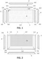
- the board (1) comprises a covering layer (1.10) and a supporting layer (1.20).
- the covering layer (1.10) defines an upper surface (A), corresponding to the useful surface of the module in a situation in which the module is used as a horizontal work surface
- the supporting layer (1.20) defines a lower surface (B), corresponding to the non-visible surface during use of the module as a work surface.
- the supporting layer comprises a reticular reinforcement mesh made, for example, of glass fiber, on its lower face.
- the upper surface (A) and the lower surface (B) define the thickness of the board (1).
- ⁇ is substantially 45°, but in other embodiments it can have another value.
- the plane containing the second front edge (1.4) of the board forms an approximate angle of 90° with the plane containing the outer surface (A) of the board.
- the first pair of side battens (2, 3) is attached to the first side edge (1.1) of the board (1) and the first pair of front battens (4, 5) is attached to the first front edge (1.2) of the board (1).
- Figures 1 to 6 show the front and side battens being decoupled from the board so that said battens may be seen better.
- one of the corners of the board has been depicted in a thicker line to serve as a visual guide.
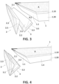
- the second longitudinal edge (2.2) of the first side batten (2) and the first longitudinal edge (3.1) of the second side batten (3) are beveled at substantially complementary angles ( ⁇ 2 , ⁇ 2 ).
- the first longitudinal edge (2.1) of the first side batten (2) and the first side edge (1.1) of the board (1) are beveled at substantially complementary angles ( ⁇ 1 , ⁇ ).
- the second longitudinal edge (3.2) of the second side batten (3) and the first side edge (1.1) of the board (1) are beveled substantially with the same bevel angle ( ⁇ 3 , ⁇ ).
- Figures 3 and 4 show the first side batten (2) and the second side batten (3), as well as the first side edge (1.1) of the board (1).
- the bevels of the first side batten (2) and of the second side batten (3) were done by means of making opposite longitudinal cuts along the length of the side battens (2, 3), at an approximate angle of 45° with respect to the plane formed by the length and the width of the batten, i.e., the plane containing the outer face of the batten.
- the first side batten (2) and the second side batten (3) are laminated battens with the same composition of layers as the laminated board, with the exception of the reinforcement mesh of the board (1) which is not present in the battens as they have a smaller thickness.
- the covering layer of the side battens (2, 3) has a maximum width corresponding to the thickness of the board, and it is the layer which is exposed at the side edge of the constructed module.
- FIG. 2 schematically shows the coupling of the first side batten (2) and the second side batten (3) to one another.
- the first longitudinal edge (2.1) of the first side batten (2) and the second longitudinal edge (3.2) of the second side batten (3) are attached to the first side edge (1.1) of the board (1).
- Figure 7 schematically shows the coupling of the second side batten (3) to the first side edge (1.1) in a situation in which the module is partially assembled.
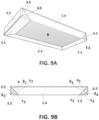
- Figures 9A and 9B show the first side batten (2) and the second side batten (3) attached to the first side edge (1.1) of the board (1).
- the outer face (2.3) of the first side batten (2) is the widest surface of the first side batten (2) and forms the exposed (or outer) face of the side edge of the module
- the outer face (3.3) of the second side batten (3) is the widest surface of the second side batten (3) and forms the exposed lower face in the proximity of the side edge of the module.
- the first pair of front battens (4, 5) comprises a first front batten (4) and a second front batten (5).
- the first front batten (4) comprises a first longitudinal edge (4.1), a second longitudinal edge (4.2), an outer face (4.3), a first end edge (4.4), and a second end edge (4.5).
- the second front batten (5) comprises a first longitudinal edge (5.1), a second longitudinal edge (5.2), an outer face (5.3), a first end edge (5.4), and a second end edge (5.5).
- the first front batten (4) and the second front batten (5) have a maximum length approximately equal to the length of the board (1), a maximum width approximately equal to the thickness of the board (1), and a maximum thickness approximately equal to half the thickness of the board (1).
- the second longitudinal edge (4.2) of the first front batten (4) and the first longitudinal edge (5.1) of the second front batten (5) are beveled at substantially complementary angles.
- the first longitudinal edge (4.1) of the first front batten (4) and the first front edge (1.2) of the board (1) are beveled at substantially complementary angles.
- the second longitudinal edge (5.2) of the second front batten (5) and the first front edge (1.2) of the board (1) are beveled substantially with the same bevel angle.
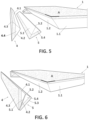
- Figures 5 and 6 show the first front batten (4) and the second front batten (5), as well as the first front edge (1.2) of the board (1).
- the bevels of the first front batten (4) and of the second front batten (5) have been made by means of making opposite longitudinal cuts along the length of the front battens (4, 5), at an approximate angle of 45° with respect to the plane formed by the length and the width of the batten, i.e., the plane containing the outer face (4.3, 5.3) of the batten.
- the first front batten (4) and the second front batten (5) are laminated battens with the same composition of layers as the laminated board, with the exception of the reinforcement mesh of the board (1) which is not present in the battens as they have a smaller thickness.
- the covering layer of the front battens (4, 5) has a maximum width corresponding to the thickness of the board, and it is the layer which is exposed (or arranged on the outside) at the front edge of the constructed module.
- FIG. 6 schematically shows the coupling of the first front batten (4) and the second front batten (5) attached to one another.
- the first longitudinal edge (4.1) of the first front batten (4) and the second longitudinal edge (5.2) of the second front batten (5) are attached to the first front edge (1.2) of the board (1).
- Figures 7 and 8 schematically show the coupling of the first front batten (4) and the second front batten (5) to the first front edge (1.2) in situations in which the module is partially assembled.
- the outer face (4.3) of the first front batten (4) is the widest surface of the first front batten (4) and forms the exposed (or outer) face of the front edge of the module
- the outer face (5.3) of the second front batten (5) is the widest surface of the second front batten (5) and forms the exposed lower face in the proximity of the front edge of the module.
- the first end edge (2.4) of the first side batten (2) and the first end edge (4.4) of the first front batten (4) are beveled at substantially complementary angles and attached to one another, with the longitudinal direction of said battens forming an approximate angle of 90°, with the outer face (2.3) of the first side batten (2) being substantially perpendicular to the outer face (4.3) of the first front batten (4).
- Figures 9A and 10 show this arrangement.
- the first end edge (2.4) of the first side batten (2) and the first end edge (4.4) of the first front batten (4) are beveled at about 45° in the plane formed by the longitudinal direction and the direction of the thickness of the corresponding batten.
- the first end edge (3.4) of the second side batten (3) and the first end edge (5.4) of the second front batten (5) are beveled at substantially complementary angles and attached to one another, with the longitudinal directions of said battens forming an approximate angle of 90°, and the outer face (3.3) of the second side batten (3) being substantially coplanar with the outer face (5.3) of the second front batten (5).
- the outer face (3.3) of the second side batten (3) and the outer face (5.3) of the second front batten (5) which are substantially coplanar with one another, are also substantially coplanar with the lower surface (B) of the board (1).
- Figures 7 and 9A show this arrangement.
- the first end edge (3.4) of the second side batten (3) and the first end edge (5.4) of the second front batten (5) are beveled at about 45° in the plane formed by the longitudinal direction and the width of the corresponding batten.
- the board comprises a second beveled side edge (1.3) and the module comprises a second pair of side battens (6, 7).
- the angle ⁇ 1 formed between the plane containing the second side edge (1.3) of the board and the plane containing the upper face (A) of the board (1) has been identified in Figure 9B .
- the second pair of side battens (6, 7) comprises a third side batten (6) and a fourth side batten (7).
- the third side batten (6) comprises a first longitudinal edge, a second longitudinal edge, an outer face (6.3), a first end edge (6.4), and a second end edge (6.5).
- the fourth side batten (7) comprises a first longitudinal edge, a second longitudinal edge, an outer face (7.3), a first end edge (7.4), and a second end edge (7.5).
- Figures 9A and 9B show the third side batten (6) and the fourth side batten (7) attached to the second side edge (1.2) of the board (1).
- the following is identified in Figure 9B : the angle ⁇ 3 formed between the plane containing the first longitudinal edge (6.1) of the third side batten (6) and the plane containing the outer face (6.3) of the third side batten (6); the angle ⁇ 4 formed between the plane containing the second longitudinal edge (6.2) of the third side batten (6) and the plane containing the outer face (6.3) of the third side batten (6); the angle ⁇ 4 formed between the plane containing the first longitudinal edge (7.1) of the fourth side batten (7) and the plane containing the outer face (7.3) of the fourth side batten (7); and the angle ⁇ 5 formed between the plane containing the second longitudinal edge (7.2) of the fourth side batten (7) and the plane containing the outer face (7.3) of the fourth side batten (7).
- the first end edge (6.4) of the third side batten (6) and the second end edge (4.5) of the first front batten (4) are beveled at substantially complementary angles and attached to one another, with the longitudinal direction of said battens forming an approximate angle of 90°, and the outer face (6.3) of the third side batten (6) being substantially perpendicular to the outer face (4.3) of the first front batten (4).
- This arrangement can be observed In Figure 8 .
- the first end edge (6.4) of the third side batten (6) and the second end edge (4.5) of the first front batten (4) are beveled at about 45° in the plane formed by the longitudinal direction and the direction of the thickness of the corresponding batten.
- the first end edge (7.4) of the fourth side batten (7) and the second end edge (5.5) of the second front batten (5) are beveled at substantially complementary angles and attached to one another, with the longitudinal direction of said battens forming an approximate angle of 90°, and the outer face (7.3) of the fourth side batten (7) being substantially coplanar with the outer face (5.3) of the second front batten (5).
- the outer face (7.3) of the fourth side batten (7) and the outer face (5.3) of the second front batten (5) which are substantially coplanar with one another, are also substantially coplanar with the lower surface (B) of the board (1). This arrangement is seen in Figure 9A .
- the first end edge (7.4) of the fourth side batten (7) and the second end edge (5.5) of the second front batten (5) are beveled at about 45° in the plane formed by the longitudinal direction and the direction of the width of the corresponding batten.
- Figure 8 shows the arrangement of the first pair of front battens (4, 5) and the second pair of side battens (6, 7) in a situation in which the module is partially assembled.
- the second end edge (2.5) of the first side batten (2), the second end edge (3.5) of the second side batten (3), the second end edge (6.5) of the third side batten (6), and the second end edge (7.5) of the fourth side batten (7) are substantially perpendicular to the longitudinal direction of the corresponding batten and substantially coplanar with the second front edge (1.4) of the board, as seen in Figure 9A .
- the board comprises two beveled side edges and the module comprises two pairs of side battens attached in said beveled side edges in the embodiment of Figures 1 to 10
- the board may have a single beveled side edge and a single pair of side battens attached to said beveled side edge.
- the second longitudinal edge of the third front batten and the first longitudinal edge of the fourth front batten are beveled at substantially complementary angles and attached to one another.
- the first longitudinal edge of the third front batten and the second front edge of the board are beveled at substantially complementary angles and attached to one another.
- the second longitudinal edge of the fourth front batten and the second front edge of the board are beveled substantially with the same bevel angle and attached to one another.
- the second end edge of the first side batten and the first end edge of the third front batten are beveled at substantially complementary angles and attached to one another such that the longitudinal directions of the first side batten and of the third front batten are substantially perpendicular and the outer face of the first side batten is substantially perpendicular to the outer face of the third front batten.
- the second end edge of the second side batten and the first end edge of the fourth front batten are beveled at substantially complementary angles and attached to one another such that the longitudinal directions of the second side batten and of the fourth front batten are substantially perpendicular, and the outer face of the second side batten is substantially coplanar with the outer face of the fourth front batten.
- the second end edge of the third side batten and the second end edge of the third front batten are beveled at substantially complementary angles and attached to one another, with the longitudinal directions of said battens forming an approximate angle of 90°, and the outer face of the third side batten being substantially perpendicular to the outer face of the third front batten.
- the second end edge of the third side batten and the second end edge of the third front batten are beveled at about 45° in the plane formed by the longitudinal direction and the direction of the thickness of the corresponding batten.
- the second end edge of the fourth side batten and the second end edge of the fourth front batten are beveled at substantially complementary angles and attached to one another, with the longitudinal directions of said battens forming an approximate angle of 90°, and the outer face of the fourth side batten being substantially coplanar with the outer face of the fourth front batten.
- the second end edge of the fourth side batten and the second end edge of the fourth front batten are beveled at about 45° in the plane formed by the longitudinal direction and the direction of the width of the corresponding batten.
- the first end edge (2.4) of the first side batten (2) and the first end edge (4.4) of the first front batten (4) are beveled at substantially complementary angles; and the first end edge (3.4) of the second side batten (3) and the first end edge (5.4) of the second front batten (5) are beveled at substantially complementary angles.
- the method additionally comprises the following steps:
- both the board (1) and the battens (2, 3, 4, 5) have one and the same configuration of layers, at least in the part closer to the external part of the covering layer.
- both the laminated board and the laminated side and front battens can all be obtained from one and the same initial laminated panel.
- this significantly simplifies module manufacture and considerably reduces waste generation.
- the method may include one or more additional steps for cutting, finishing, and/or working the laminated module to adapt it to its final application. Therefore, the method may include a step of cutting the module to the size required by the application, a step for chamfering the borders of the module, and/or a step for cutting out at least one hole for the insertion of an element such as a sink or a cooking plate.
- these steps can be performed with conventional cutting tools in woodworking or carpentry.
- the supporting layer can be formed by a laminate having several sheets of materials with different characteristics. Therefore, for example, the supporting layer can be formed by a laminate with a polymeric foam laminated to a layer of fiber mesh, a metal sheet, or a plastic sheet.
- any material used today as a work surface such as worktops
- a material providing the required mechanical strength and chemical resistance, and preferably having good esthetic qualities (for example, relative to color patterns, shine, and/or type of surface finishing) is selected for the covering layer for this application.
- the examples of materials which can be used for the covering layer are ceramic materials obtained from mineral sintering, such as porcelain materials, natural stones (for example, granite or marble), and artificial stones of the composite type, such as quartz or bauxite composites.
- the use of high-density wood laminates or solid wood boards as the covering layer can also be envisaged.
- the side battens are cut from the same initial laminated panel.
- the four side battens include a first side batten (2), a second side batten (3), a third side batten (6), and a fourth side batten (7).
- Said end forms a beveled end edge (2.4), in which the plane containing the end edge (2.4) forms an angle ⁇ with the plane containing the outer face (2.3).
- Figures 12a to 12c show, respectively, views of the first side batten (2) from the part of the supporting layer (2.20), profile views from the second longitudinal edge (2.2) and from the outer face (2.3).
- Two front battens (4, 5) are additionally cut from the same initial laminated panel ( Figures 14 and 15 ).
- the maximum length (L F ) of the front battens is approximately equal to the length (L) of the board, that is, 3.0 m.
- the two front battens (4, 5) are cut such that they are beveled at 45° along their length to form the longitudinal edges (4.1, 4.2, 5.1, 5.2), such that the widest face of each batten which defines the outer face of the batten is the one corresponding to the covering layer (4.10, 5.10), and the maximum thickness (t F ) thereof is about half the thickness (t) of the board, that is, 15 mm.
- the longitudinal cuts are made at approximate angles of 45° on each longitudinal edge of the batten, in the plane formed by the width (w F ) and the thickness (t F ) of the front battens (4, 5). Therefore, the plane containing the outer face and the plane containing the longitudinal edge form an approximate angle of 45° on each side of the batten.
- the first end edge (5.4) and the second end edge (5.5) of the second front batten (5) are thus formed.
- the cut is made such that the plane containing the end edge (5.4, 5.5) forms an approximate angle of 90° with the plane containing the outer face (5.3) of the batten, and where the area of the first longitudinal edge (5.1) is larger than the area of the second longitudinal edge (5.2).
- Figures 15a to 15c showing, respectively: schematic views of the second front batten (5), where (a) is the profile view from the second longitudinal edge (5.2), (b) is the view from the part of the supporting layer (5.20), and (c) is the view from the outer face (5.3).
- the module is formed by the seven mentioned parts, i.e., the laminated board (1), the first side batten (2), the second side batten (3), the third side batten (6), the fourth side batten (7), the first front batten (4), and the second front batten (5).
- the second front edge (1.4) of the board which will form a front edge of the module is cut at 90°, without battens adhered thereto, and with the supporting layer (1.20) exposed. In a situation in which the module is used, this second front edge (1.4) will be concealed facing a wall or a piece of furniture, and, therefore, the reinforcement or a more esthetic finishing thereof is not necessary.
- the module may include a different number of pairs of battens, for example a single pair of side battens attached to a side edge of the board and a single pair of front battens attached to a front edge of the board, or two pairs of front battens and two pairs of side battens attached, respectively, to the side and front edges of the board.
- the bevel angles are about 45° in this example, other angle values are possible for the different cuts, and the same bevel angle for all the battens is not necessary either.
- the first side batten (2) and the second side batten (3) are attached to one another
- the third side batten (6) and the fourth side batten (7) are attached to one another
- the first front batten (4) and the second front batten (5) are attached to one another.
- the attachment is carried out with an adhesive.
- the batten assemblies are attached with an adhesive to the beveled side and front edges, respectively, of the board.
- Figures 16a and 16b show, by way of example, the position of the battens with respect to the board before and after the attachment.
- the covering layer (1.10) of the board (1) forms the upper surface (A) of the module.
- the covering layers (2.10, 6.10) of the first side batten (2) and the third side batten (6) form the side edges of the module, whereas the covering layer (4.10) of the first front batten (4) forms a front edge of the module.
- the covering layers (3.10, 7.10, 5.10) of the second side batten (3), the fourth side batten (7), and the second front batten (5) form the lower surface of the module in the proximity of the side edges and the front edge.
- the rest of the lower surface of the module is formed by the lower surface (B) of the board (1).
- these covering layers (3.10, 7.10, 5.10) of the second and fourth side battens, and the second front batten are substantially coplanar, and they are also coplanar with the lower surface of the board.
- the invention is not limited to this described way of manufacturing the module, but rather another order of steps, or the performance of two or more steps simultaneously, is possible without departing from the inventive concept. Therefore, for example, it is possible to gradually attach the different battens individually to the board with an adhesive.
- the module of the invention is much more lightweight than monolayer stone or ceramic boards of a similar size and may be cut or produced with conventional carpentry tools, where specific marble working tools are not required. Furthermore, since the edges are better protected, it better withstands transport and minor impacts in the area of the edges.
- a hole like those made for inserting a glass ceramic plate in a worktop, is made in the two modules thus constructed.
- the hole had dimensions of 50 x 50 cm and was made at a distance of 5 cm from the front edge of each module.
- a bending strength test of the two modules was performed by placing, in both cases, different increasing weights in the area of the module located between the front edge of the module and the hole.
- the edge and the module were capable of supporting 75 kg before showing small cracks.
- the comparative module with the edges finished at an angle of 90° with an adhered Dekton ® strip showed cracks when 30 kg were applied and broke when a weight of 70 kg was applied.
Landscapes
- Engineering & Computer Science (AREA)
- Manufacturing & Machinery (AREA)
- Chemical & Material Sciences (AREA)
- Ceramic Engineering (AREA)
- Finishing Walls (AREA)
Claims (15)
- Un module stratifié comprenant un panneau stratifié (1), une première paire de lattes latérales (2, 3) et une première paire de lattes avant (4, 5) ;le panneau (1) comprenant une couche de revêtement (1.10) et une couche de support (1.20), la couche de revêtement (1.10) définissant une surface supérieure (A) et la couche de support (1.20) définissant une surface inférieure (B), et le panneau (1) comprenant un premier bord latéral (1.1) et un premier bord avant (1.2), tous deux biseautés de telle sorte que la surface supérieure (A) du panneau soit plus grande que la surface inférieure (B) du panneau ;la première paire de lattes latérales (2, 3) comprenant une première latte latérale (2) et une deuxième latte latérale (3) ; la première latte latérale (2) comprenant un premier bord longitudinal (2.1) et un deuxième bord longitudinal (2.2), une face extérieure (2.3), ainsi qu'un premier bord d'extrémité (2.4) et un deuxième bord d'extrémité (2.5) ; la deuxième latte latérale (3) comprenant un premier bord longitudinal (3.1) et un deuxième bord longitudinal (3.2), une face extérieure (3.3), ainsi qu'un premier bord d'extrémité (3.4) et un deuxième bord d'extrémité (3.5) ;la première paire de lattes avant (4, 5) comprenant une première latte avant (4) et une deuxième latte avant (5) ; la première latte avant (4) comprenant un premier bord longitudinal (4.1) et un deuxième bord longitudinal (4.2), une face extérieure (4.3), ainsi qu'un premier bord d'extrémité (4.4) et un deuxième bord d'extrémité (4.5) ; la deuxième latte avant (5) comprenant un premier bord longitudinal (5.1) et un deuxième bord longitudinal (5.2), une face extérieure (5.3), ainsi qu'un premier bord d'extrémité (5.4) et un deuxième bord d'extrémité (5.5) ;dans lequel :le deuxième bord longitudinal (2.2) de la première latte latérale (2) et le premier bord longitudinal (3.1) de la deuxième latte latérale (3) sont biseautés selon des angles sensiblement complémentaires et sont fixés l'un à l'autre ;le premier bord longitudinal (2.1) de la première latte latérale (2) et le premier bord latéral (1.1) du panneau (1) sont biseautés selon des angles sensiblement complémentaires et sont fixés l'un à l'autre ;le deuxième bord longitudinal (3.2) de la deuxième latte latérale (3) et le premier bord latéral (1.1) du panneau (1) sont biseautés sensiblement selon le même angle de biseau et sont fixés l'un à l'autre ;le deuxième bord longitudinal (4.2) de la première latte avant (4) et le premier bord longitudinal (5.1) de la deuxième latte avant (5) sont biseautés selon des angles sensiblement complémentaires et sont fixés l'un à l'autre ;le premier bord longitudinal (4.1) de la première latte avant (4) et le premier bord avant (1.2) du panneau (1) sont biseautés selon des angles sensiblement complémentaires et sont fixés l'un à l'autre ;le deuxième bord longitudinal (5.2) de la deuxième latte avant (5) et le premier bord avant (1.2) du panneau (1) sont biseautés sensiblement avec le même angle de biseau et sont fixés l'un à l'autre ;le premier bord d'extrémité (2.4) de la première latte latérale (2) et le premier bord d'extrémité (4.4) de la première latte avant (4) sont biseautés selon des angles sensiblement complémentaires et sont fixés l'un à l'autre de telle sorte que les directions longitudinales de la première latte latérale (2) et de la première latte avant (4) sont sensiblement perpendiculaires et la face extérieure (2.3) de la première latte latérale (2) est sensiblement perpendiculaire à la face extérieure (4.3) de la première latte avant (4) ; etle premier bord d'extrémité (3.4) de la deuxième latte latérale (3) et le premier bord d'extrémité (5.4) de la deuxième latte avant (5) sont biseautés selon des angles sensiblement complémentaires et sont fixés l'un à l'autre de telle sorte que les directions longitudinales de la deuxième latte latérale (3) et de la deuxième latte avant (5) sont sensiblement perpendiculaires, et la face extérieure (3.3) de la deuxième latte latérale (3) est sensiblement coplanaire avec la face extérieure (5.3) de la deuxième latte avant (5) .
- Le module selon la revendication précédente, dans lequel le premier bord latéral (1.1) et/ou le premier bord avant (1.2) du panneau (1) est biseauté avec un angle de biseau compris entre 40° et 50°, de préférence entre 43° et 47°.
- Le module selon l'une des revendications précédentes, dans lequel le deuxième bord longitudinal (2.2) de la première latte latérale (2) et/ou le deuxième bord longitudinal (4.2) de la première latte avant (4) est biseauté avec un angle de biseau compris entre 40° et 50°, de préférence entre 43° et 47°.
- Le module selon l'une quelconque des revendications précédentes, dans lequel le premier bord d'extrémité (2.4) de la première latte latérale (2) et/ou le premier bord d'extrémité (3.4) de la deuxième latte latérale (3) est biseauté avec un angle de biseau compris entre 40° et 50°, de préférence entre 43° et 47°.
- Le module selon l'une quelconque des revendications précédentes, dans lequel :la première latte latérale (2) et la deuxième latte latérale (3) ont une longueur sensiblement égale à la largeur du panneau (1), une largeur sensiblement égale à l'épaisseur du panneau (1), et une épaisseur sensiblement égale à la moitié de l'épaisseur du panneau (1) ; et/oula première latte avant (4) et la deuxième latte avant (5) ont une longueur sensiblement égale à la longueur du panneau (1), une largeur sensiblement égale à l'épaisseur du panneau (1), et une épaisseur sensiblement égale à la moitié de l'épaisseur du panneau (1) .
- Le module selon l'une quelconque des revendications précédentes, dans lequel au moins une parmi la première latte latérale (2), la deuxième latte latérale (3), la première latte avant (4) et la deuxième latte avant (5) est une latte stratifiée comprenant une couche de revêtement (3.10, 5.10) et une couche de support (3.20, 5.20).
- Le module selon la revendication précédente, dans lequel :l'épaisseur de la couche de revêtement de la latte stratifiée (3.10, 5.10) est comprise entre 2 et 10 mm, de préférence encore entre 3 et 8 mm ; et/oul'épaisseur de la couche de support (3.20, 5.20) de la latte stratifiée est comprise entre 5 et 20 mm, de préférence encore entre 7 et 17 mm.
- Le module selon l'une quelconque des revendications précédentes, dans lequel la couche de revêtement (1.10, 3.10, 5.10) a une épaisseur inférieure à la couche de support (1.20, 3.20, 5.20).
- Le module selon l'une quelconque des revendications précédentes, dans lequel :l'épaisseur de la couche de revêtement (1.10) du panneau (1) est comprise entre 2 et 10 mm, de préférence encore entre 3 et 8 mm ; et/oul'épaisseur de la couche de support (1.20) du panneau (1) est comprise entre 10 et 40 mm, de préférence encore entre 15 et 35 mm.
- Le module selon l'une quelconque des revendications précédentes, dans lequel le panneau (1) comprend un deuxième bord latéral biseauté (1.3) et le module comprend une deuxième paire de lattes latérales (6, 7) ; la deuxième paire de lattes latérales (6, 7) comprend une troisième latte latérale (6) et une quatrième latte latérale (7) ; la troisième latte latérale (6) comprenant un premier bord longitudinal et un deuxième bord longitudinal, une face extérieure (6.3), et un premier bord d'extrémité (6.4) et un deuxième bord d'extrémité (6.5) ; la quatrième latte latérale (7) comprenant un premier bord longitudinal (7.4) et un deuxième bord longitudinal (7.5), une face extérieure (7.3), ainsi qu'un premier bord d'extrémité (7.4) et un deuxième bord d'extrémité (7.5) ;
dans lequel :le deuxième bord longitudinal de la troisième latte latérale (6) et le premier bord longitudinal de la quatrième latte latérale (7) sont biseautés selon des angles sensiblement complémentaires et sont fixés l'un à l'autre ;le premier bord longitudinal de la troisième latte latérale (6) et le deuxième bord latéral (1.3) du panneau (1) sont biseautés selon des angles sensiblement complémentaires et sont fixés l'un à l'autre ;le deuxième bord longitudinal de la quatrième latte latérale (7) et le deuxième bord latéral (1.3) du panneau (1) sont biseautés sensiblement avec le même angle de biseau et sont fixés l'un à l'autre ;le premier bord d'extrémité (6.4) de la troisième latte latérale (6) et le deuxième bord d'extrémité (4.5) de la première latte avant (4) sont biseautés selon des angles sensiblement complémentaires et sont fixés l'un à l'autre de telle sorte que les directions longitudinales de la troisième latte latérale (6) et la première latte avant (4) sont sensiblement perpendiculaires et la face extérieure de la troisième latte latérale (6) est sensiblement perpendiculaire à la face extérieure (4.3) de la première latte avant (4) ; etle premier bord d'extrémité de la quatrième latte latérale (7) et le deuxième bord d'extrémité de la deuxième latte avant (5) sont biseautés selon des angles sensiblement complémentaires et sont fixés l'un à l'autre de telle sorte que les directions longitudinales de la quatrième latte latérale (7) et de la deuxième latte avant (5) sont sensiblement perpendiculaires, et la face extérieure de la quatrième latte latérale (7) est sensiblement coplanaire avec la face extérieure (5.3) de la deuxième latte avant (5). - Le module selon l'une quelconque des revendications précédentes, dans lequel le panneau (1) comprend un deuxième bord avant biseauté (1.4) et le module comprend une deuxième paire de lattes avant ; la deuxième paire de lattes avant comprend une troisième latte avant et une quatrième latte avant ; la troisième latte avant comprenant un premier bord longitudinal et un deuxième bord longitudinal, une face extérieure, ainsi qu'un premier bord d'extrémité et un deuxième bord d'extrémité ; la quatrième latte avant comprenant un premier bord longitudinal et un deuxième bord longitudinal, une face extérieure, ainsi qu'un premier bord d'extrémité et un deuxième bord d'extrémité ;
dans lequel :le deuxième bord longitudinal de la troisième latte avant et le premier bord longitudinal de la quatrième latte avant sont biseautés selon des angles sensiblement complémentaires et sont fixés l'un à l'autre ;le premier bord longitudinal de la troisième latte avant et le deuxième bord avant (1.4) du panneau (1) sont biseautés selon des angles sensiblement complémentaires et sont fixés l'un à l'autre ;le deuxième bord longitudinal de la quatrième latte avant et le deuxième bord avant (1.4) du panneau (1) sont biseautés sensiblement avec le même angle de biseau et sont fixés l'un à l'autre ;le deuxième bord d'extrémité de la première latte latérale (2) et le premier bord d'extrémité de la troisième latte avant sont biseautés selon des angles sensiblement complémentaires et sont fixés l'un à l'autre de telle sorte que les directions longitudinales de la première latte latérale (2) et de la troisième latte avant sont sensiblement perpendiculaires et la face extérieure (2.3) de la première latte latérale (2) est sensiblement perpendiculaire à la face extérieure de la troisième latte avant ; etle deuxième bord d'extrémité de la deuxième latte latérale (3) et le premier bord d'extrémité de la quatrième latte avant sont biseautés selon des angles sensiblement complémentaires et sont fixés l'un à l'autre de telle sorte que la direction longitudinale de la deuxième latte latérale (3) et de la quatrième latte avant soit sensiblement perpendiculaire, et que la face extérieure (3.3) de la deuxième latte latérale (3) soit sensiblement coplanaire avec la face extérieure de la quatrième latte avant. - Procédé de fabrication d'un module selon l'une quelconque des revendications précédentes qui comprend les étapes suivantes :a) le fait de fournir un panneau stratifié (1) comprenant une couche de revêtement (1.10) et une couche de support (1.20), la couche de revêtement (1.10) définissant une surface supérieure (A) et la couche de support (1.20) définissant une surface inférieure (B) ; et le panneau (1) comprend un premier bord latéral (1.1) et un premier bord avant (1.2), tous deux biseautés de telle sorte que la surface supérieure (A) du panneau est plus grande que la surface inférieure (B) du panneau ;b) le fait de prévoir une première latte latérale (2) et une deuxième latte latérale (3) ; la première latte latérale (2) comprenant un premier bord longitudinal (2.1) et un deuxième bord longitudinal (2.2), une face extérieure (2.3), ainsi qu'un premier bord d'extrémité (2.4) et un deuxième bord d'extrémité (2.5) ; la deuxième latte latérale (3) comprenant un premier bord longitudinal (3.1) et un deuxième bord longitudinal (3.2), une face extérieure (3.3), ainsi qu'un premier bord d'extrémité (3.4) et un deuxième bord d'extrémité (3.5) ; le deuxième bord longitudinal (2.2) de la première latte latérale (2) et le premier bord longitudinal (3.1) de la deuxième latte latérale (3) sont biseautés selon des angles sensiblement complémentaires ; le premier bord longitudinal (2.1) de la première latte latérale (2) et le premier bord latéral (1.1) du panneau (1) sont biseautés selon des angles sensiblement complémentaires ; et
le deuxième bord longitudinal (3.2) de la deuxième latte latérale (3) et le premier bord latéral (1.1) du panneau (1) sont biseautés sensiblement avec le même angle de biseau ;c) le fait de prévoir une première latte avant (4) et une deuxième latte avant (5) ; la première latte avant (4) comprenant un premier bord longitudinal (4.1) et un deuxième bord longitudinal (4.2), une face extérieure (4.3), ainsi qu'un premier bord d'extrémité (4.4) et un deuxième bord d'extrémité (4.5) ; la deuxième latte avant (5) comprenant un premier bord longitudinal (5.1) et un deuxième bord longitudinal (5.2), une face extérieure (5.3), ainsi qu'un premier bord d'extrémité (5.4) et un deuxième bord d'extrémité (5.5) ; le deuxième bord longitudinal (4.2) de la première latte avant (4) et le premier bord longitudinal (5.1) de la deuxième latte avant (5) sont biseautés selon des angles sensiblement complémentaires ; le premier bord longitudinal (4.1) de la première latte avant (4) et le premier bord avant (1.2) du panneau (1) sont biseautés selon des angles sensiblement complémentaires ; et le deuxième bord longitudinal (5.2) de la deuxième latte avant (5) et le premier bord avant (1.2) du panneau (1) sont biseautés sensiblement avec le même angle de biseau ;d) le fait de fixer le deuxième bord longitudinal (2.2) de la première latte latérale (2) et le premier bord longitudinal (3.1) de la deuxième latte latérale (3) ;e) le fait de fixer le premier bord longitudinal (2.1) de la première latte latérale (2) et le premier bord latéral (1.1) du panneau (1) ;f) le fait de fixer le deuxième bord longitudinal (3.2) de la deuxième latte latérale (3) et le premier bord latéral (1.1) du panneau (1) ;g) le fait de fixer le deuxième bord longitudinal (4.2) de la première latte avant (4) et le premier bord longitudinal (5.1) de la deuxième latte avant (5) ;h) le fait de fixer le premier bord longitudinal (4.1) de la première latte avant (4) et le premier bord avant (1.2) du panneau (1) ;i) le fait de fixer le deuxième bord longitudinal (5.2) de la deuxième latte avant (5) et le premier bord avant (1.2) du panneau (1). - Le procédé selon la revendication précédente, dans lequel :le premier bord d'extrémité (2.4) de la première latte latérale (2) et le premier bord d'extrémité (4.4) de la première latte avant (4) sont biseautés selon des angles sensiblement complémentaires ; etle premier bord d'extrémité (3.4) de la deuxième latte latérale (3) et le premier bord d'extrémité (5.4) de la deuxième latte avant (5) sont biseautés selon des angles sensiblement complémentaires ;le procédé comprenant en outre :j) le fait de fixer le premier bord d'extrémité (2.4) de la première latte latérale (2) et le premier bord d'extrémité (4.4) de la première latte avant (4) de telle sorte que les directions longitudinales de la première latte latérale (2) et de la première latte avant (4) sont sensiblement perpendiculaires et la face externe (2.3) de la première latte latérale (2) est sensiblement perpendiculaire à la face externe (4.3) de la première latte avant (4) ;k) le fait de fixer le premier bord d'extrémité (3.4) de la deuxième latte latérale (3) et le premier bord d'extrémité (5.4) de la deuxième latte avant (5) de telle sorte que la direction longitudinale de la deuxième latte latérale (3) et de la deuxième latte avant (5) sont sensiblement perpendiculaires, et la face externe (3.3) de la deuxième latte latérale (3) est sensiblement coplanaire avec la face externe (5.3) de la deuxième latte avant (5).
- Le procédé selon l'une des revendications 12 à 13, dans lequel les étapes a) à c) résultent des étapes antérieures suivantes :le fait de fournir un panneau stratifié ; etle fait de découper le panneau pour obtenir le panneau (1), la première latte latérale (2), la deuxième latte latérale (3), la première latte avant (4), et la deuxième latte avant (5).
- Le procédé selon la revendication précédente, dans lequel l'étape de fourniture d'un panneau stratifié comprend le fait de fixer une couche de support sur une couche de revêtement.
Priority Applications (3)
| Application Number | Priority Date | Filing Date | Title |
|---|---|---|---|
| ES20382284T ES2988566T3 (es) | 2020-04-08 | 2020-04-08 | Módulo laminado y método de fabricación del mismo |
| EP20382284.6A EP3892154B1 (fr) | 2020-04-08 | 2020-04-08 | Module laminé et méthode de fabrication de celui-ci |
| US17/220,542 US20210316525A1 (en) | 2020-04-08 | 2021-04-01 | Laminated Module And Method Of Manufacturing The Same |
Applications Claiming Priority (1)
| Application Number | Priority Date | Filing Date | Title |
|---|---|---|---|
| EP20382284.6A EP3892154B1 (fr) | 2020-04-08 | 2020-04-08 | Module laminé et méthode de fabrication de celui-ci |
Publications (2)
| Publication Number | Publication Date |
|---|---|
| EP3892154A1 EP3892154A1 (fr) | 2021-10-13 |
| EP3892154B1 true EP3892154B1 (fr) | 2024-07-03 |
Family
ID=70975831
Family Applications (1)
| Application Number | Title | Priority Date | Filing Date |
|---|---|---|---|
| EP20382284.6A Active EP3892154B1 (fr) | 2020-04-08 | 2020-04-08 | Module laminé et méthode de fabrication de celui-ci |
Country Status (3)
| Country | Link |
|---|---|
| US (1) | US20210316525A1 (fr) |
| EP (1) | EP3892154B1 (fr) |
| ES (1) | ES2988566T3 (fr) |
Families Citing this family (12)
| Publication number | Priority date | Publication date | Assignee | Title |
|---|---|---|---|---|
| US20240254778A1 (en) * | 2023-01-30 | 2024-08-01 | Safeboard LLC | Slab support |
| US12378776B2 (en) * | 2023-10-02 | 2025-08-05 | Moderno Porcelain Works, LLC | Porcelain board tile assemblies, systems, and methods for surface installations |
| US12359442B2 (en) * | 2023-10-02 | 2025-07-15 | Moderno Porcelain Works, LLC | Reinforced porcelain panel product for enhanced structural protection |
| US12264480B1 (en) * | 2023-10-02 | 2025-04-01 | Moderno Porcelain Works, LLC | Reinforced porcelain panel product for enhanced structural protection |
| US12241258B1 (en) * | 2023-10-02 | 2025-03-04 | Moderno Porcelain Works, LLC | Reinforced porcelain panel product fabrication methods for enhanced structural protection |
| US12364368B2 (en) | 2023-10-02 | 2025-07-22 | Moderno Porcelain Works, LLC | Reinforced porcelain panel magnetic assemblies, systems, and methods for shower installations |
| US12247403B1 (en) * | 2023-10-02 | 2025-03-11 | Moderno Porcelain Works, LLC | Reinforced porcelain panel product and associated methods for enhanced structural protection |
| US12227951B1 (en) * | 2023-10-02 | 2025-02-18 | Moderno Porcelain Works, LLC | Reinforced porcelain panel product kit for shower installation |
| US12297647B1 (en) * | 2023-10-02 | 2025-05-13 | Moderno Porcelain Works, LLC | Reinforced porcelain panel product kit for shower installation |
| US12297646B1 (en) | 2023-10-02 | 2025-05-13 | Moderno Porcelain Works, LLC | Reinforced porcelain panel product fabrication methods for enhanced structural protection |
| US12435520B2 (en) | 2023-10-02 | 2025-10-07 | Moderno Porcelain Works, LLC | Reinforced porcelain panel system and associated methods for enhanced structural protection |
| US12241259B1 (en) * | 2023-10-02 | 2025-03-04 | Moderno Porcelain Works, LLC | Porcelain board tile assemblies, systems, and methods for surface installations |
Citations (1)
| Publication number | Priority date | Publication date | Assignee | Title |
|---|---|---|---|---|
| US20110281131A1 (en) * | 2010-05-17 | 2011-11-17 | Roberts Richard A | Decorative trim panel |
Family Cites Families (6)
| Publication number | Priority date | Publication date | Assignee | Title |
|---|---|---|---|---|
| IT1320157B1 (it) | 2000-01-27 | 2003-11-18 | Combistone Italia S P A | Piano e/o rivestimento per arredamento e procedimento per la suaproduzione. |
| US6773538B2 (en) * | 2002-12-06 | 2004-08-10 | Ronald Lee Blessing | Method of making countertops |
| ITVI20030164A1 (it) | 2003-08-07 | 2005-02-08 | Marmo Arredo Srl | Pannello multistrato |
| DE202006016106U1 (de) | 2006-10-18 | 2007-02-01 | Naturstein Jäschke GmbH | Dünnsteinplatte |
| AU2008202351B2 (en) * | 2007-05-30 | 2014-04-03 | Lbt Investments Pty Ltd | Bench top arrangement and method of forming a bench top arrangement |
| KR20170056137A (ko) * | 2015-11-13 | 2017-05-23 | 이남용 | 완충 코너부를 구비한 가구 바디 및 제조방법 |
-
2020
- 2020-04-08 EP EP20382284.6A patent/EP3892154B1/fr active Active
- 2020-04-08 ES ES20382284T patent/ES2988566T3/es active Active
-
2021
- 2021-04-01 US US17/220,542 patent/US20210316525A1/en not_active Abandoned
Patent Citations (1)
| Publication number | Priority date | Publication date | Assignee | Title |
|---|---|---|---|---|
| US20110281131A1 (en) * | 2010-05-17 | 2011-11-17 | Roberts Richard A | Decorative trim panel |
Also Published As
| Publication number | Publication date |
|---|---|
| EP3892154A1 (fr) | 2021-10-13 |
| US20210316525A1 (en) | 2021-10-14 |
| ES2988566T3 (es) | 2024-11-20 |
Similar Documents
| Publication | Publication Date | Title |
|---|---|---|
| EP3892154B1 (fr) | Module laminé et méthode de fabrication de celui-ci | |
| CN113646494B (zh) | 一种基于矿物的地板镶板 | |
| US4931331A (en) | Laminated tile product, method for producing the same and method for installing the same | |
| CA2489679C (fr) | Panneaux en relief modulaires et methodes de fabrication | |
| CN100485150C (zh) | 具有被压紧边缘的建筑面板 | |
| US6698149B1 (en) | Composite laminated building material, and methods of making and using same | |
| KR20200039660A (ko) | 플로어 패널 및 이런 플로어 패널을 제조하는 방법 | |
| EP1867804A2 (fr) | Panneau de finition avec marbre | |
| US5062913A (en) | Laminated tile product and method for producing the same | |
| US6199334B1 (en) | Composite cladding system | |
| US20230366212A1 (en) | Tile with imitation grout line | |
| US7883597B2 (en) | Composite bevel siding | |
| EP2971391B1 (fr) | Plaque de plâtre pour plafond acoustique monolithique | |
| EP3882018B1 (fr) | Panneau décoratif ou plateau | |
| US6395116B1 (en) | Method for manufacturing counter top edging from floor tile | |
| CN111133161A (zh) | 一种镶嵌式复合地板块 | |
| KR100790193B1 (ko) | 대리석을 이용한 장식재 및 그 제조방법 | |
| US20260055608A1 (en) | Heat and moisture resistant subfloor and optional ceiling structures made using lightweight composite panels | |
| EP3789555A1 (fr) | Kit de construction d'une structure modulaire, structure modulaire, méthode d'assemblage et son utilisation | |
| KR200388421Y1 (ko) | 적층체 | |
| WO2007079555A1 (fr) | Procede de fabrication d'un mur en panneaux de platre | |
| Gragnaniello | Study and executive design of a ventilated facade with porcelain stoneware cladding | |
| JPH0529876Y2 (fr) | ||
| EP3332962A1 (fr) | Élément de construction composite et procédé pour son obtention | |
| PL240011B1 (pl) | Kamienna płyta dekoracyjna oraz sposób wytwarzania kamiennej płyty wielowarstwowej |
Legal Events
| Date | Code | Title | Description |
|---|---|---|---|
| PUAI | Public reference made under article 153(3) epc to a published international application that has entered the european phase |
Free format text: ORIGINAL CODE: 0009012 |
|
| STAA | Information on the status of an ep patent application or granted ep patent |
Free format text: STATUS: THE APPLICATION HAS BEEN PUBLISHED |
|
| AK | Designated contracting states |
Kind code of ref document: A1 Designated state(s): AL AT BE BG CH CY CZ DE DK EE ES FI FR GB GR HR HU IE IS IT LI LT LU LV MC MK MT NL NO PL PT RO RS SE SI SK SM TR |
|
| STAA | Information on the status of an ep patent application or granted ep patent |
Free format text: STATUS: REQUEST FOR EXAMINATION WAS MADE |
|
| 17P | Request for examination filed |
Effective date: 20220406 |
|
| RBV | Designated contracting states (corrected) |
Designated state(s): AL AT BE BG CH CY CZ DE DK EE ES FI FR GB GR HR HU IE IS IT LI LT LU LV MC MK MT NL NO PL PT RO RS SE SI SK SM TR |
|
| STAA | Information on the status of an ep patent application or granted ep patent |
Free format text: STATUS: EXAMINATION IS IN PROGRESS |
|
| 17Q | First examination report despatched |
Effective date: 20221107 |
|
| GRAP | Despatch of communication of intention to grant a patent |
Free format text: ORIGINAL CODE: EPIDOSNIGR1 |
|
| STAA | Information on the status of an ep patent application or granted ep patent |
Free format text: STATUS: GRANT OF PATENT IS INTENDED |
|
| INTG | Intention to grant announced |
Effective date: 20240129 |
|
| GRAS | Grant fee paid |
Free format text: ORIGINAL CODE: EPIDOSNIGR3 |
|
| GRAA | (expected) grant |
Free format text: ORIGINAL CODE: 0009210 |
|
| STAA | Information on the status of an ep patent application or granted ep patent |
Free format text: STATUS: THE PATENT HAS BEEN GRANTED |
|
| AK | Designated contracting states |
Kind code of ref document: B1 Designated state(s): AL AT BE BG CH CY CZ DE DK EE ES FI FR GB GR HR HU IE IS IT LI LT LU LV MC MK MT NL NO PL PT RO RS SE SI SK SM TR |
|
| REG | Reference to a national code |
Ref country code: CH Ref legal event code: EP |
|
| REG | Reference to a national code |
Ref country code: DE Ref legal event code: R096 Ref document number: 602020033261 Country of ref document: DE |
|
| REG | Reference to a national code |
Ref country code: LT Ref legal event code: MG9D |
|
| REG | Reference to a national code |
Ref country code: NL Ref legal event code: MP Effective date: 20240703 |
|
| REG | Reference to a national code |
Ref country code: ES Ref legal event code: FG2A Ref document number: 2988566 Country of ref document: ES Kind code of ref document: T3 Effective date: 20241120 |
|
| PG25 | Lapsed in a contracting state [announced via postgrant information from national office to epo] |
Ref country code: PT Free format text: LAPSE BECAUSE OF FAILURE TO SUBMIT A TRANSLATION OF THE DESCRIPTION OR TO PAY THE FEE WITHIN THE PRESCRIBED TIME-LIMIT Effective date: 20241104 |
|
| REG | Reference to a national code |
Ref country code: AT Ref legal event code: MK05 Ref document number: 1698885 Country of ref document: AT Kind code of ref document: T Effective date: 20240703 |
|
| PG25 | Lapsed in a contracting state [announced via postgrant information from national office to epo] |
Ref country code: NL Free format text: LAPSE BECAUSE OF FAILURE TO SUBMIT A TRANSLATION OF THE DESCRIPTION OR TO PAY THE FEE WITHIN THE PRESCRIBED TIME-LIMIT Effective date: 20240703 |
|
| PG25 | Lapsed in a contracting state [announced via postgrant information from national office to epo] |
Ref country code: PT Free format text: LAPSE BECAUSE OF FAILURE TO SUBMIT A TRANSLATION OF THE DESCRIPTION OR TO PAY THE FEE WITHIN THE PRESCRIBED TIME-LIMIT Effective date: 20241104 Ref country code: NL Free format text: LAPSE BECAUSE OF FAILURE TO SUBMIT A TRANSLATION OF THE DESCRIPTION OR TO PAY THE FEE WITHIN THE PRESCRIBED TIME-LIMIT Effective date: 20240703 |
|
| PG25 | Lapsed in a contracting state [announced via postgrant information from national office to epo] |
Ref country code: NO Free format text: LAPSE BECAUSE OF FAILURE TO SUBMIT A TRANSLATION OF THE DESCRIPTION OR TO PAY THE FEE WITHIN THE PRESCRIBED TIME-LIMIT Effective date: 20241003 |
|
| PG25 | Lapsed in a contracting state [announced via postgrant information from national office to epo] |
Ref country code: FI Free format text: LAPSE BECAUSE OF FAILURE TO SUBMIT A TRANSLATION OF THE DESCRIPTION OR TO PAY THE FEE WITHIN THE PRESCRIBED TIME-LIMIT Effective date: 20240703 Ref country code: GR Free format text: LAPSE BECAUSE OF FAILURE TO SUBMIT A TRANSLATION OF THE DESCRIPTION OR TO PAY THE FEE WITHIN THE PRESCRIBED TIME-LIMIT Effective date: 20241004 Ref country code: PL Free format text: LAPSE BECAUSE OF FAILURE TO SUBMIT A TRANSLATION OF THE DESCRIPTION OR TO PAY THE FEE WITHIN THE PRESCRIBED TIME-LIMIT Effective date: 20240703 |
|
| PG25 | Lapsed in a contracting state [announced via postgrant information from national office to epo] |
Ref country code: BG Free format text: LAPSE BECAUSE OF FAILURE TO SUBMIT A TRANSLATION OF THE DESCRIPTION OR TO PAY THE FEE WITHIN THE PRESCRIBED TIME-LIMIT Effective date: 20240703 |
|
| PG25 | Lapsed in a contracting state [announced via postgrant information from national office to epo] |
Ref country code: LV Free format text: LAPSE BECAUSE OF FAILURE TO SUBMIT A TRANSLATION OF THE DESCRIPTION OR TO PAY THE FEE WITHIN THE PRESCRIBED TIME-LIMIT Effective date: 20240703 |
|
| PG25 | Lapsed in a contracting state [announced via postgrant information from national office to epo] |
Ref country code: AT Free format text: LAPSE BECAUSE OF FAILURE TO SUBMIT A TRANSLATION OF THE DESCRIPTION OR TO PAY THE FEE WITHIN THE PRESCRIBED TIME-LIMIT Effective date: 20240703 Ref country code: IS Free format text: LAPSE BECAUSE OF FAILURE TO SUBMIT A TRANSLATION OF THE DESCRIPTION OR TO PAY THE FEE WITHIN THE PRESCRIBED TIME-LIMIT Effective date: 20241103 |
|
| PG25 | Lapsed in a contracting state [announced via postgrant information from national office to epo] |
Ref country code: HR Free format text: LAPSE BECAUSE OF FAILURE TO SUBMIT A TRANSLATION OF THE DESCRIPTION OR TO PAY THE FEE WITHIN THE PRESCRIBED TIME-LIMIT Effective date: 20240703 Ref country code: CZ Free format text: LAPSE BECAUSE OF FAILURE TO SUBMIT A TRANSLATION OF THE DESCRIPTION OR TO PAY THE FEE WITHIN THE PRESCRIBED TIME-LIMIT Effective date: 20240703 |
|
| PG25 | Lapsed in a contracting state [announced via postgrant information from national office to epo] |
Ref country code: RS Free format text: LAPSE BECAUSE OF FAILURE TO SUBMIT A TRANSLATION OF THE DESCRIPTION OR TO PAY THE FEE WITHIN THE PRESCRIBED TIME-LIMIT Effective date: 20241003 |
|
| PG25 | Lapsed in a contracting state [announced via postgrant information from national office to epo] |
Ref country code: RS Free format text: LAPSE BECAUSE OF FAILURE TO SUBMIT A TRANSLATION OF THE DESCRIPTION OR TO PAY THE FEE WITHIN THE PRESCRIBED TIME-LIMIT Effective date: 20241003 Ref country code: PL Free format text: LAPSE BECAUSE OF FAILURE TO SUBMIT A TRANSLATION OF THE DESCRIPTION OR TO PAY THE FEE WITHIN THE PRESCRIBED TIME-LIMIT Effective date: 20240703 Ref country code: NO Free format text: LAPSE BECAUSE OF FAILURE TO SUBMIT A TRANSLATION OF THE DESCRIPTION OR TO PAY THE FEE WITHIN THE PRESCRIBED TIME-LIMIT Effective date: 20241003 Ref country code: LV Free format text: LAPSE BECAUSE OF FAILURE TO SUBMIT A TRANSLATION OF THE DESCRIPTION OR TO PAY THE FEE WITHIN THE PRESCRIBED TIME-LIMIT Effective date: 20240703 Ref country code: IS Free format text: LAPSE BECAUSE OF FAILURE TO SUBMIT A TRANSLATION OF THE DESCRIPTION OR TO PAY THE FEE WITHIN THE PRESCRIBED TIME-LIMIT Effective date: 20241103 Ref country code: HR Free format text: LAPSE BECAUSE OF FAILURE TO SUBMIT A TRANSLATION OF THE DESCRIPTION OR TO PAY THE FEE WITHIN THE PRESCRIBED TIME-LIMIT Effective date: 20240703 Ref country code: GR Free format text: LAPSE BECAUSE OF FAILURE TO SUBMIT A TRANSLATION OF THE DESCRIPTION OR TO PAY THE FEE WITHIN THE PRESCRIBED TIME-LIMIT Effective date: 20241004 Ref country code: FI Free format text: LAPSE BECAUSE OF FAILURE TO SUBMIT A TRANSLATION OF THE DESCRIPTION OR TO PAY THE FEE WITHIN THE PRESCRIBED TIME-LIMIT Effective date: 20240703 Ref country code: CZ Free format text: LAPSE BECAUSE OF FAILURE TO SUBMIT A TRANSLATION OF THE DESCRIPTION OR TO PAY THE FEE WITHIN THE PRESCRIBED TIME-LIMIT Effective date: 20240703 Ref country code: BG Free format text: LAPSE BECAUSE OF FAILURE TO SUBMIT A TRANSLATION OF THE DESCRIPTION OR TO PAY THE FEE WITHIN THE PRESCRIBED TIME-LIMIT Effective date: 20240703 Ref country code: AT Free format text: LAPSE BECAUSE OF FAILURE TO SUBMIT A TRANSLATION OF THE DESCRIPTION OR TO PAY THE FEE WITHIN THE PRESCRIBED TIME-LIMIT Effective date: 20240703 |
|
| REG | Reference to a national code |
Ref country code: DE Ref legal event code: R097 Ref document number: 602020033261 Country of ref document: DE |
|
| PG25 | Lapsed in a contracting state [announced via postgrant information from national office to epo] |
Ref country code: SM Free format text: LAPSE BECAUSE OF FAILURE TO SUBMIT A TRANSLATION OF THE DESCRIPTION OR TO PAY THE FEE WITHIN THE PRESCRIBED TIME-LIMIT Effective date: 20240703 Ref country code: DK Free format text: LAPSE BECAUSE OF FAILURE TO SUBMIT A TRANSLATION OF THE DESCRIPTION OR TO PAY THE FEE WITHIN THE PRESCRIBED TIME-LIMIT Effective date: 20240703 Ref country code: RO Free format text: LAPSE BECAUSE OF FAILURE TO SUBMIT A TRANSLATION OF THE DESCRIPTION OR TO PAY THE FEE WITHIN THE PRESCRIBED TIME-LIMIT Effective date: 20240703 |
|
| PG25 | Lapsed in a contracting state [announced via postgrant information from national office to epo] |
Ref country code: EE Free format text: LAPSE BECAUSE OF FAILURE TO SUBMIT A TRANSLATION OF THE DESCRIPTION OR TO PAY THE FEE WITHIN THE PRESCRIBED TIME-LIMIT Effective date: 20240703 |
|
| PG25 | Lapsed in a contracting state [announced via postgrant information from national office to epo] |
Ref country code: SK Free format text: LAPSE BECAUSE OF FAILURE TO SUBMIT A TRANSLATION OF THE DESCRIPTION OR TO PAY THE FEE WITHIN THE PRESCRIBED TIME-LIMIT Effective date: 20240703 |
|
| PLBE | No opposition filed within time limit |
Free format text: ORIGINAL CODE: 0009261 |
|
| STAA | Information on the status of an ep patent application or granted ep patent |
Free format text: STATUS: NO OPPOSITION FILED WITHIN TIME LIMIT |
|
| 26N | No opposition filed |
Effective date: 20250404 |
|
| PGFP | Annual fee paid to national office [announced via postgrant information from national office to epo] |
Ref country code: DE Payment date: 20250429 Year of fee payment: 6 |
|
| PGFP | Annual fee paid to national office [announced via postgrant information from national office to epo] |
Ref country code: GB Payment date: 20250428 Year of fee payment: 6 Ref country code: ES Payment date: 20250505 Year of fee payment: 6 |
|
| PGFP | Annual fee paid to national office [announced via postgrant information from national office to epo] |
Ref country code: IT Payment date: 20250422 Year of fee payment: 6 |
|
| PGFP | Annual fee paid to national office [announced via postgrant information from national office to epo] |
Ref country code: FR Payment date: 20250425 Year of fee payment: 6 |
|
| PG25 | Lapsed in a contracting state [announced via postgrant information from national office to epo] |
Ref country code: SE Free format text: LAPSE BECAUSE OF FAILURE TO SUBMIT A TRANSLATION OF THE DESCRIPTION OR TO PAY THE FEE WITHIN THE PRESCRIBED TIME-LIMIT Effective date: 20240703 |
|
| REG | Reference to a national code |
Ref country code: CH Ref legal event code: H13 Free format text: ST27 STATUS EVENT CODE: U-0-0-H10-H13 (AS PROVIDED BY THE NATIONAL OFFICE) Effective date: 20251125 |
|
| PG25 | Lapsed in a contracting state [announced via postgrant information from national office to epo] |
Ref country code: LU Free format text: LAPSE BECAUSE OF NON-PAYMENT OF DUE FEES Effective date: 20250408 |
|
| PG25 | Lapsed in a contracting state [announced via postgrant information from national office to epo] |
Ref country code: MC Free format text: LAPSE BECAUSE OF FAILURE TO SUBMIT A TRANSLATION OF THE DESCRIPTION OR TO PAY THE FEE WITHIN THE PRESCRIBED TIME-LIMIT Effective date: 20240703 |
|
| REG | Reference to a national code |
Ref country code: BE Ref legal event code: MM Effective date: 20250430 |
|
| PG25 | Lapsed in a contracting state [announced via postgrant information from national office to epo] |
Ref country code: BE Free format text: LAPSE BECAUSE OF NON-PAYMENT OF DUE FEES Effective date: 20250430 |
|
| PG25 | Lapsed in a contracting state [announced via postgrant information from national office to epo] |
Ref country code: CH Free format text: LAPSE BECAUSE OF NON-PAYMENT OF DUE FEES Effective date: 20250430 |
|
| PG25 | Lapsed in a contracting state [announced via postgrant information from national office to epo] |
Ref country code: IE Free format text: LAPSE BECAUSE OF NON-PAYMENT OF DUE FEES Effective date: 20250408 |