EP3892802A1 - Agencement de poignée de porte - Google Patents
Agencement de poignée de porte Download PDFInfo
- Publication number
- EP3892802A1 EP3892802A1 EP20168322.4A EP20168322A EP3892802A1 EP 3892802 A1 EP3892802 A1 EP 3892802A1 EP 20168322 A EP20168322 A EP 20168322A EP 3892802 A1 EP3892802 A1 EP 3892802A1
- Authority
- EP
- European Patent Office
- Prior art keywords
- door handle
- door
- handles
- retracted position
- arrangement according
- Prior art date
- Legal status (The legal status is an assumption and is not a legal conclusion. Google has not performed a legal analysis and makes no representation as to the accuracy of the status listed.)
- Granted
Links
Images




Classifications
-
- E—FIXED CONSTRUCTIONS
- E05—LOCKS; KEYS; WINDOW OR DOOR FITTINGS; SAFES
- E05B—LOCKS; ACCESSORIES THEREFOR; HANDCUFFS
- E05B1/00—Knobs or handles for wings; Knobs, handles, or press buttons for locks or latches on wings
- E05B1/003—Handles pivoted about an axis perpendicular to the wing
-
- E—FIXED CONSTRUCTIONS
- E05—LOCKS; KEYS; WINDOW OR DOOR FITTINGS; SAFES
- E05B—LOCKS; ACCESSORIES THEREFOR; HANDCUFFS
- E05B1/00—Knobs or handles for wings; Knobs, handles, or press buttons for locks or latches on wings
- E05B1/0092—Moving otherwise than only rectilinearly or only rotatively
-
- E—FIXED CONSTRUCTIONS
- E05—LOCKS; KEYS; WINDOW OR DOOR FITTINGS; SAFES
- E05B—LOCKS; ACCESSORIES THEREFOR; HANDCUFFS
- E05B13/00—Devices preventing the key or the handle or both from being used
- E05B13/002—Devices preventing the key or the handle or both from being used locking the handle
-
- E—FIXED CONSTRUCTIONS
- E05—LOCKS; KEYS; WINDOW OR DOOR FITTINGS; SAFES
- E05B—LOCKS; ACCESSORIES THEREFOR; HANDCUFFS
- E05B3/00—Fastening knobs or handles to lock or latch parts
- E05B3/003—Fastening knobs or handles to hollow cylindrical spindles, e.g. of tubular locks
-
- E—FIXED CONSTRUCTIONS
- E05—LOCKS; KEYS; WINDOW OR DOOR FITTINGS; SAFES
- E05B—LOCKS; ACCESSORIES THEREFOR; HANDCUFFS
- E05B47/00—Operating or controlling locks or other fastening devices by electric or magnetic means
- E05B47/06—Controlling mechanically-operated bolts by electro-magnetically-operated detents
- E05B47/0657—Controlling mechanically-operated bolts by electro-magnetically-operated detents by locking the handle, spindle, follower or the like
-
- E—FIXED CONSTRUCTIONS
- E05—LOCKS; KEYS; WINDOW OR DOOR FITTINGS; SAFES
- E05B—LOCKS; ACCESSORIES THEREFOR; HANDCUFFS
- E05B5/00—Handles completely let into the surface of the wing
- E05B5/003—Pop-out handles, e.g. sliding outwardly before rotation
-
- E—FIXED CONSTRUCTIONS
- E05—LOCKS; KEYS; WINDOW OR DOOR FITTINGS; SAFES
- E05B—LOCKS; ACCESSORIES THEREFOR; HANDCUFFS
- E05B1/00—Knobs or handles for wings; Knobs, handles, or press buttons for locks or latches on wings
- E05B1/0015—Knobs or handles which do not operate the bolt or lock, e.g. non-movable; Mounting thereof
- E05B2001/0023—Knobs or handles which do not operate the bolt or lock, e.g. non-movable; Mounting thereof being movable into a non-operating position, e.g. foldable towards the mounting plane
-
- E—FIXED CONSTRUCTIONS
- E05—LOCKS; KEYS; WINDOW OR DOOR FITTINGS; SAFES
- E05B—LOCKS; ACCESSORIES THEREFOR; HANDCUFFS
- E05B1/00—Knobs or handles for wings; Knobs, handles, or press buttons for locks or latches on wings
- E05B2001/0076—The handle having at least two operating positions, e.g. the bolt can be retracted by moving the handle either upwards or downwards
Definitions
- the invention relates to a door handle arrangement for a building door with a mortise lock.
- the door handle arrangement considered here is used for building doors.
- Building doors can be any single-leaf or double-leaf doors, in particular revolving doors, on or in buildings.
- a mortise lock is usually used in a building door. Therefore, a door handle with a pin is inserted into the socket of the mortise lock from one side of the door. On the opposite side, a complementary second door handle is pushed onto the mandrel and usually fastened with a grub screw.
- the door handle for. B. with the door open, protrude into a passage area and be a hindrance.
- clothing can get caught on the door handle or the passage area can be too narrow due to the door handle. This is particularly relevant, for example, if the door cannot be opened beyond 90 ° and as a result the door handle protrudes into the passage area.
- a retractable and extendable door handle on at least one side of a building door can enable safe and practical use of the door.
- this makes it possible to move the door handle into the retracted position when it is not in use, so that it does not protrude into a passage area, for example.
- the door handle arrangement comprises a first and a second door handle, designed for arrangement on two opposite sides of the building door.
- the door handles are preferably door handles.
- Door handles can also be referred to as door handles.
- the door handle has, in particular, a grip area that can be gripped by a user and pressed down. By pressing the handle area downwards, the door handle is rotated. This rotary movement is transmitted to the socket of the mortise lock, whereby the latch of the mortise lock can be retracted.
- At least one of the two door handles is designed otherwise, for example as a knob.
- the knob is preferably rotatable in order to also set the socket of the mortise lock in rotation.
- the door handle assembly also has a spike element.
- This mandrel element can also be referred to as a "mandrel” and fulfills the torque-transmitting function from the door handle arrangement to the socket of the mortise lock.
- the nut of the mortise lock in turn can, as in conventional mortise locks, be designed as a square socket.
- the socket of the mortise lock is designed otherwise, in particular as any form-locking element. It is crucial that the pin element of the door handle arrangement can be inserted into the socket of the mortise lock and that a torque-transmitting connection between the pin element and socket is possible as a result.
- the mandrel element has a non-circular cross section so that a positive torque transmission to the nut is made possible.
- the mandrel element is "at least non-rotatably connected" to one of the two door handles.
- the mandrel element in addition to the rotationally fixed connection, is also linearly fixed, i. H. not linearly movable, can be connected to this door handle.
- the mandrel element can also be made in one piece with this door handle.
- the pin element is additionally connected to the other door handle in a rotationally fixed manner, so that the pin element can be turned by actuating both door handles.
- At least one of the two door handles can be moved into a retracted position and into an extended position.
- the door handle or the handle area of the door handle is as close as possible to the mortise lock or the building door.
- the door handle cannot be grasped and used in the retracted position.
- the door handle is in the extended position correspondingly far away from the mortise lock or the building door, so that the handle area of this door handle can be grasped and consequently used.
- Usable here means in particular that the door handle can be pressed by the user.
- the grip area of the movable door handle in the retracted position rests against a sign and / or the building door, in particular is sunk into the sign and / or the building door.
- the two door handles are slidably plugged into one another for adjustment between the two positions.
- one of the two door handles cannot be displaced and the other door handle is displaceable, so that the door handle can be moved into the retracted and extended position on one side of the building door, whereas the door handle cannot be moved on the other side of the building door - and is extendable.
- the door handle arrangement preferably comprises an actuator arrangement.
- the actuator arrangement is designed to move at least one of the two door handles into the retracted position and / or into the extended position.
- the actuator arrangement is preferably located inside the door handle arrangement.
- Both door handles preferably each comprise a handle area and a plug-in area.
- the two plug-in areas of the door handles are at least partially plugged into one another.
- the actuator arrangement is located inside the two plug-in areas of the door handles.
- the actuator arrangement can be designed to move the corresponding door handle in only one direction, that is to say, for example, into the retracted or into the extended position, or can be designed to do so be able to move the door handle in both directions, i.e. both in the retracted position and in the extended position.
- the actuator arrangement comprises a pressure catch and / or a controllable unit.
- the snap catch is a component that is known, for example, from furniture construction. Such push catches are also referred to as furniture dampers with a push-to-open function.
- the controllable unit is in particular an electromechanical, pneumatic or hydraulic unit.
- the actuator arrangement can also include both:
- the controllable unit can be used to move the door handle into the retracted position and thereby tension the push catch.
- the pressure catch can then be released again for the movement into the extended position.
- the pressure catch is in particular arranged in such a way that it is compressed when the door handle is moved into the retracted position, be it by a user pressing the door handle or by moving the door handle by means of the controllable unit.
- a spiral spring is compressed in the interior of the pressure catch and held in this state.
- a socket axis is preferably defined on the door handle arrangement.
- the two plug-in areas of the door handles extend parallel to the socket axis. The movement between the retracted and extended position takes place in particular parallel to the socket axis.
- the pressure catch described is preferably arranged parallel to the nut axis.
- the compression or release of the pressure catch also takes place parallel to the nut axis.
- the electromechanical, pneumatic or hydraulic unit for moving the door handle is preferably controlled by means of a control unit.
- this control unit can be part of a door device.
- the control unit can be on the door of the building or anywhere else.
- the data connection between the control unit and the actuator arrangement can be wired or wireless.
- the control unit can be used to drive the door handle in and / or out in any way.
- the control unit can detect an access authorization of a user and activates the actuator arrangement in response to this access authorization.
- the acquisition of the access authorization by means of the control unit takes place in particular by sending a corresponding signal from a smartphone of the user to the control unit and / or by other recognition of the user, for example via a fingerprint or an optical acquisition.
- the door handle can be moved accordingly via the control unit and the actuator arrangement.
- the first door handle is connected to the pin element in a rotationally and linearly fixed manner or is manufactured in one piece with the pin element. In this constellation, the first door handle does not move relative to the pin element.
- the second door handle is in the first door handle. Only the second door handle can be moved into the retracted position and into the extended position.
- the mandrel element is here preferably formed by an outer contour of the first door handle.
- This outer contour can be an integral part of the first door handle, in particular the plug-in area of the first door handle.
- an element is arranged on the outer circumference of the plug-in area of the first door handle in order to form the spike element.
- Both door handles are preferably plugged into one another in the area of the mandrel element. This means in particular that the two plug-in areas overlap at the level of the mandrel element.
- the first door handle has an outer tube. This outer tube is located in particular in the plug-in area of the first door handle.
- the mandrel element is formed or arranged on the outside of the outer tube.
- the first door handle comprises an inner element arranged in the outer tube and an annular gap between the outer tube and the inner element.
- the inner element is in particular an elongated component inserted into the outer tube.
- the inner element and the outer tube are preferably connected to one another in a rotationally and linearly fixed manner, for example by means of a grub screw and / or a corresponding form fit.
- the second door handle is linearly movable in the annular gap.
- the inner element is preferably hollow on the inside for receiving the actuator arrangement.
- the controllable unit and / or the pressure catch are preferably located in the inner element, which is hollow on the inside. Because the hollow inner element is open towards the second door handle, the actuator arrangement can protrude from the inner element in the direction of the second door handle and thereby move the second door handle relative to the first door handle.
- the inner element preferably has an outer polygon.
- the second door handle in particular in its hollow plug-in area, preferably has an inner polygon seated non-rotatably on the outer polygon. This results in a connection between the two door handles that is linearly movable along the socket axis, but non-rotatable.
- the mandrel element can be rotated using both door handles.
- the second door handle is connected to the pin element in a rotationally and linearly fixed manner or is manufactured in one piece with the pin element.
- the plug-in area of the second door handle is designed as a mandrel or mandrel element.
- the second door handle is in the first door handle and only the second door handle can be moved into the retracted and extended position.
- the first door handle remains fixed relative to the mortise lock.
- the mandrel element that is to say in particular the plug-in area of the second door handle, is inserted into a guide sleeve.
- the second door handle is accommodated in this guide sleeve so that it can move linearly along the socket axis but is non-rotatable.
- the guide sleeve is preferably fastened in the building door or on the mortise lock in such a way that it can be rotated but not moved linearly.
- the plug-in area of the second door handle has a slot.
- a guide pin is arranged in this slot.
- the guide pin is fixedly arranged in the guide sleeve, so that the combination of guide pin and slot limits the linear mobility of the second door handle. This ensures that the second door handle cannot be completely pulled out of the socket.
- the first door handle is hollow in its plug-in area for receiving the plug-in area of the second door handle.
- the second door handle is linearly movable and non-rotatable in the first door handle, so that the spike element can be rotated by turning both door handles.
- the two door handles are designed in an arc shape.
- the respective grip areas merge directly and in an arc shape into the plug-in areas.
- the two arched door handles also plug into one another and at least one of the two door handles can be retracted and extended. During this movement between the retracted and extended position, the two door handles are moved or plugged into one another in an arc shape relative to one another, in particular along an arc of a circle.
- the invention further comprises a door device.
- the door device includes the building door, the mortise lock with nut and the door handle assembly described.
- the advantageous refinements and subclaims described in the context of the door handle arrangement are also used correspondingly for the door device according to the invention.
- the door device comprises the control unit described.
- the door handle arrangement there is in particular the actuator arrangement described, controllable by the control unit.
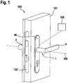
- Figures 1 to 11 an embodiment of a door device 100 with a door handle arrangement 1 is described.
- Figures 1 to 4 show the basic structure for all variants of the door handle arrangement 1 shown here
- Figures 5 to 10 four different variants of the door handle arrangement 1 are shown.
- Figure 11 shows in detail a door plate 40 that can be used in all variants.
- the door device 100 comprises a building door 101 which can be used on or in a building.
- a mortise lock 102 is located in the building door 101.
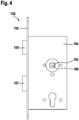
- Two possible configurations of the mortise lock 102 are shown in FIG Figures 3 and 4th shown.
- the door device 100 further comprises the door handle arrangement 1, which will be described in detail below.
- an actuator arrangement 7 can be used, which can be controlled via a control device 109.
- the control unit 109 and the data connection to the door handle assembly 1 is in the Figures 1 and 2 shown purely schematically.
- the door handle arrangement 1 comprises a first door handle 3 and a second door handle 4 on the two opposite sides of the building door 101.
- Figure 1 shows an extended position of the second door handle 4.
- the second door handle 4 can be grasped and used.
- Figure 2 shows the second door handle 4 in a retracted position. The second door handle 4 cannot be grasped and therefore cannot be used.
- FIGS 3 and 4th show two possible configurations of the mortise lock 102.
- the mortise lock 102 comprises a lock case 104 which is inserted into the building door 101 up to the stop of the faceplate 105.
- a socket 103 is provided which can be rotated about a socket axis 108.
- the rotatable follower 103 is mechanically connected to a latch 106 and possibly also to a bolt 107. By turning the nut 103, the latch 106 and / or the bolt 107 can be moved.
- Figure 4 shows a conventional embodiment of the socket 103 with an internal square in which a conventional mandrel with a square cross-section can be inserted along the socket axis 108.
- FIG 3 makes it clear that within the scope of the present invention, nuts 103 configured in other ways are also used on mortise locks 102 Can apply. Since at least one of the door handles 3, 4 can be inserted into the other door handle 3, 4, it can be advantageous to provide the largest possible cross section in the area of the socket 103. So shows Figure 3 that the mortise lock 102 can also have a relatively large socket 103 with any cross section designed to transmit positive torque.
- the first door handle 3 is in each case firmly connected to a mandrel element 2 or configured in one piece.
- the second door handle 4 is inserted in the first door handle 3 and can be moved parallel to the socket axis 108 into the retracted position and the extended position.
- the mandrel element 2 is inserted into the socket 103 and is connected to the socket 103 in a rotationally fixed manner due to the cross-sections of the mandrel element 2 or the socket 103.
- the two door handles 3, 4 each have a grip area 5 and a plug-in area 6.
- the two plug-in areas 6 of the door handles 3, 4 plug into one another in a linearly movable manner.
- Both plug-in areas 6 are hollow on the inside and plug into one another.
- the actuator arrangement 7, shown purely schematically, can be arranged in the interior of the two plug-in areas 6.
- the actuator arrangement 7 includes the snap snap described in the general part of the description and / or the controllable unit.
- Figure 6 shows another variant in a purely schematic representation.
- the two door handles 3, 4 are curved and also plug into one another.
- the two door handles 3, 4 are plugged into one another or pulled apart relative to one another along an arc, in particular an arc of a circle. Due to the arched configuration, the handle areas 5 in the two door handles 3, 4 merge directly into the plug-in areas 6.
- the plug area 6 or the handle area 5 of the second door handle 4 can dip into the entire first door handle 3, i.e. both the handle area 5 and the plug area 6 of the first door handle 3, when moving into the retracted position.
- mandrel element 2 is not as in Figure 5 must be formed directly by the outer contour of the first door handle 3, but can also be formed by a plugged-on or otherwise applied element.
- Figures 7 and 8 show a further variant of the door handle arrangement 1.
- Figure 7 shows an exploded view of the door handle arrangement 1.
- Figure 8 shows an associated sectional view.
- the two Figures 7, 8 show that the first door handle 3 has an outer tube 20 which essentially represents the plug-in area 6 of the first door handle 3.
- the mandrel element 2 is located on this outer tube 20. This mandrel element 2 fits, for example, into the socket 103 of the mortise lock 102 according to FIG Figure 3 .
- the outer tube 20 is hollow on the inside for receiving an inner element 21.
- the inner element 21 is positively inserted in the bottom of the outer tube 20 and is secured by means of a grub screw 25.
- the inner element 21 is connected to the outer tube 20 in a rotationally as well as linearly fixed manner.
- An annular gap 22 is formed between the outer tube 20 and the inner element 21.
- the plug-in area 6 of the second door handle 4 is also hollow and is inserted in the annular gap 22. As a result, the inner element 21 protrudes into the plug-in area 6 of the second door handle 4.
- the inner element 22 has an outer polygon 23.
- the plug-in area 6 of the second door handle 4 has a polygonal socket 24.
- the polygonal socket 23 and polygonal socket 24 plug into one another in a linearly movable manner, so that the two door handles 3, 4 are non-rotatable with respect to one another, but are movable linearly along the socket axis 108.
- a ring lock 26 fastened to the plug-in area 6 of the second door handle 4 serves as a guide and / or pull-out protection.
- the inner element 21 is preferably designed to be hollow for receiving the actuator arrangement 7 and is open in the direction of the second door handle 4, so that the actuator arrangement 7 can protrude from the inner element 21.
- Figures 9 and 10 show a further variant of the door handle arrangement 1.
- the second door handle 4 that is to say the movable door handle, is connected to the mandrel element 2 in a rotationally and linearly fixed manner or is designed in one piece.
- the entire plug-in area 6 of the second door handle 4 is designed as a mandrel element 2.
- the plug-in area 6 of the first door handle 3 has a corresponding cavity for inserting the mandrel element 2.
- the connection between the pin element 2 and the first door handle 3 is linearly movable and non-rotatable, so that the pin element 2 can be rotated via both door handles 3, 4.
- a guide sleeve 30 is preferably provided here.
- the guide sleeve 30 is located in the interior of the door leaf, in particular between the mortise lock 102 and the plate 40.
- the mandrel element 2 is linearly movable, but non-rotatably guided.
- the mandrel element 2 has a slot 32.
- a guide pin 33 which in turn is firmly connected to the guide sleeve 30, is arranged in this slot 32.
- the length of the slot 32 limits the linear mobility of the second door handle 4.
- first door handle 3 On the immovable first door handle 3 there is preferably a clamping sleeve 31, by means of which the first door handle 3 can be rotatably but linearly fixed to the building door 101 or the mortise lock 102.
- Figure 11 shows a possible construction of the shield 40 for all the variants presented here.
- the shield 40 covers the openings in the door leaf leading to the mortise lock 102.
- the shield 40 has a through hole 41 through which the plug-in area 6 of the second door handle 4 protrudes.
- a handle recess 42 is provided in the area of this through hole 41.
- the handle recess 42 is a region of the shield 40 with a reduced thickness. The thickness is measured here parallel to the socket axis 108.
- the shape of the handle recess 42 corresponds to the shape of the handle area 5 of the second door handle 4.
- the grip area 5 emerges in the retracted position into this handle recess 42 of the shield 40, so that the second door handle 4 can be positioned as close as possible to the building door 1.
Landscapes
- Engineering & Computer Science (AREA)
- Mechanical Engineering (AREA)
- Lock And Its Accessories (AREA)
- Power-Operated Mechanisms For Wings (AREA)
Priority Applications (1)
| Application Number | Priority Date | Filing Date | Title |
|---|---|---|---|
| EP20168322.4A EP3892802B1 (fr) | 2020-04-06 | 2020-04-06 | Agencement de poignée de porte |
Applications Claiming Priority (1)
| Application Number | Priority Date | Filing Date | Title |
|---|---|---|---|
| EP20168322.4A EP3892802B1 (fr) | 2020-04-06 | 2020-04-06 | Agencement de poignée de porte |
Publications (2)
| Publication Number | Publication Date |
|---|---|
| EP3892802A1 true EP3892802A1 (fr) | 2021-10-13 |
| EP3892802B1 EP3892802B1 (fr) | 2023-06-14 |
Family
ID=70224299
Family Applications (1)
| Application Number | Title | Priority Date | Filing Date |
|---|---|---|---|
| EP20168322.4A Active EP3892802B1 (fr) | 2020-04-06 | 2020-04-06 | Agencement de poignée de porte |
Country Status (1)
| Country | Link |
|---|---|
| EP (1) | EP3892802B1 (fr) |
Citations (4)
| Publication number | Priority date | Publication date | Assignee | Title |
|---|---|---|---|---|
| US791669A (en) * | 1904-09-20 | 1905-06-06 | James S Brandon | Safety-lock. |
| GB666937A (en) * | 1949-11-17 | 1952-02-20 | Saunders Roe Ltd | Improvements in or relating to handles for doors |
| WO2003064794A1 (fr) * | 2002-01-29 | 2003-08-07 | Investigación Y Transferencia De Tecnología, S.L. | Serrure de securite |
| CN204139727U (zh) * | 2014-08-20 | 2015-02-04 | 蔡婷婷 | 一种把手可隐藏的门锁 |
-
2020
- 2020-04-06 EP EP20168322.4A patent/EP3892802B1/fr active Active
Patent Citations (4)
| Publication number | Priority date | Publication date | Assignee | Title |
|---|---|---|---|---|
| US791669A (en) * | 1904-09-20 | 1905-06-06 | James S Brandon | Safety-lock. |
| GB666937A (en) * | 1949-11-17 | 1952-02-20 | Saunders Roe Ltd | Improvements in or relating to handles for doors |
| WO2003064794A1 (fr) * | 2002-01-29 | 2003-08-07 | Investigación Y Transferencia De Tecnología, S.L. | Serrure de securite |
| CN204139727U (zh) * | 2014-08-20 | 2015-02-04 | 蔡婷婷 | 一种把手可隐藏的门锁 |
Also Published As
| Publication number | Publication date |
|---|---|
| EP3892802B1 (fr) | 2023-06-14 |
Similar Documents
| Publication | Publication Date | Title |
|---|---|---|
| EP1485556B1 (fr) | Serrure | |
| EP3884127B1 (fr) | Garniture de porte présentant une poignée pouvant être verrouillée d'un côté | |
| DE29820711U1 (de) | Drehriegelverschluß mit Zugeinrichtung | |
| EP3207197B1 (fr) | Élément d'actionnement pour une serrure à palastre | |
| DE102007044088A1 (de) | Binär codierter Schlüssel und manipulationssicheres Schloss | |
| EP0819810B1 (fr) | Ferrure pour une serrure | |
| EP2025837A1 (fr) | Poignée rotative pour la serrure d'une aile de fenêtre ou analogue et procédé d'actionnement de la serrure | |
| DE202008004173U1 (de) | Verriegelungsvorrichtung | |
| DE102013010835A1 (de) | Versenkbares Druckknopfelement für ein verschließbares oder abschließbares Möbelteil | |
| EP4060147B1 (fr) | Dispositifs d'actionnement pour une serrure, ainsi que systèmes serrures pourvus de tels dispositifs d'actionnement | |
| EP1719861A2 (fr) | Serrure cylindrique pour un système de verrouillage électronique | |
| DE10225490B4 (de) | Schloss | |
| DE202014100045U1 (de) | Sicherheitsverschluss mit einem Drehspannverschluss | |
| EP3913175A1 (fr) | Dispositif d'actionnement pour une serrure, ainsi que système de fermeture doté d'un tel dispositif d'actionnement | |
| EP3034728B1 (fr) | Dispositif limiteur d'ouverture | |
| EP3299546A1 (fr) | Disque à trancher pour fouillot de panique | |
| EP3892802B1 (fr) | Agencement de poignée de porte | |
| EP4089253B1 (fr) | Système de fermeture et porte et fenêtre pourvues du système de fermeture | |
| EP3670799A1 (fr) | Dispositif de verrouillage | |
| DE3840183A1 (de) | Beschlag fuer fenster oder tueren | |
| EP2792828A2 (fr) | Dispositif de maintien en position fermée pour portes coulissantes et dispositif de fermeture pour portes coulissantes | |
| WO2009039899A1 (fr) | Serrure électronique | |
| DE202021100558U1 (de) | Verriegelungseinrichtung für ein Betätigungshandhabenpaar einer Tür | |
| EP0913550A2 (fr) | Crémone-serrure | |
| DE202011005241U1 (de) | Stangenführung |
Legal Events
| Date | Code | Title | Description |
|---|---|---|---|
| PUAI | Public reference made under article 153(3) epc to a published international application that has entered the european phase |
Free format text: ORIGINAL CODE: 0009012 |
|
| STAA | Information on the status of an ep patent application or granted ep patent |
Free format text: STATUS: THE APPLICATION HAS BEEN PUBLISHED |
|
| AK | Designated contracting states |
Kind code of ref document: A1 Designated state(s): AL AT BE BG CH CY CZ DE DK EE ES FI FR GB GR HR HU IE IS IT LI LT LU LV MC MK MT NL NO PL PT RO RS SE SI SK SM TR |
|
| STAA | Information on the status of an ep patent application or granted ep patent |
Free format text: STATUS: REQUEST FOR EXAMINATION WAS MADE |
|
| 17P | Request for examination filed |
Effective date: 20220330 |
|
| RBV | Designated contracting states (corrected) |
Designated state(s): AL AT BE BG CH CY CZ DE DK EE ES FI FR GB GR HR HU IE IS IT LI LT LU LV MC MK MT NL NO PL PT RO RS SE SI SK SM TR |
|
| RIC1 | Information provided on ipc code assigned before grant |
Ipc: E05B 5/02 20060101ALI20221122BHEP Ipc: E05B 47/06 20060101ALI20221122BHEP Ipc: E05B 13/00 20060101ALI20221122BHEP Ipc: E05B 3/00 20060101ALI20221122BHEP Ipc: E05B 1/00 20060101AFI20221122BHEP |
|
| GRAP | Despatch of communication of intention to grant a patent |
Free format text: ORIGINAL CODE: EPIDOSNIGR1 |
|
| STAA | Information on the status of an ep patent application or granted ep patent |
Free format text: STATUS: GRANT OF PATENT IS INTENDED |
|
| INTG | Intention to grant announced |
Effective date: 20230112 |
|
| GRAS | Grant fee paid |
Free format text: ORIGINAL CODE: EPIDOSNIGR3 |
|
| GRAA | (expected) grant |
Free format text: ORIGINAL CODE: 0009210 |
|
| STAA | Information on the status of an ep patent application or granted ep patent |
Free format text: STATUS: THE PATENT HAS BEEN GRANTED |
|
| AK | Designated contracting states |
Kind code of ref document: B1 Designated state(s): AL AT BE BG CH CY CZ DE DK EE ES FI FR GB GR HR HU IE IS IT LI LT LU LV MC MK MT NL NO PL PT RO RS SE SI SK SM TR |
|
| REG | Reference to a national code |
Ref country code: CH Ref legal event code: EP |
|
| REG | Reference to a national code |
Ref country code: DE Ref legal event code: R096 Ref document number: 502020003761 Country of ref document: DE |
|
| REG | Reference to a national code |
Ref country code: AT Ref legal event code: REF Ref document number: 1579340 Country of ref document: AT Kind code of ref document: T Effective date: 20230715 |
|
| REG | Reference to a national code |
Ref country code: LT Ref legal event code: MG9D |
|
| REG | Reference to a national code |
Ref country code: NL Ref legal event code: MP Effective date: 20230614 |
|
| PG25 | Lapsed in a contracting state [announced via postgrant information from national office to epo] |
Ref country code: SE Free format text: LAPSE BECAUSE OF FAILURE TO SUBMIT A TRANSLATION OF THE DESCRIPTION OR TO PAY THE FEE WITHIN THE PRESCRIBED TIME-LIMIT Effective date: 20230614 Ref country code: NO Free format text: LAPSE BECAUSE OF FAILURE TO SUBMIT A TRANSLATION OF THE DESCRIPTION OR TO PAY THE FEE WITHIN THE PRESCRIBED TIME-LIMIT Effective date: 20230914 Ref country code: ES Free format text: LAPSE BECAUSE OF FAILURE TO SUBMIT A TRANSLATION OF THE DESCRIPTION OR TO PAY THE FEE WITHIN THE PRESCRIBED TIME-LIMIT Effective date: 20230614 |
|
| PG25 | Lapsed in a contracting state [announced via postgrant information from national office to epo] |
Ref country code: RS Free format text: LAPSE BECAUSE OF FAILURE TO SUBMIT A TRANSLATION OF THE DESCRIPTION OR TO PAY THE FEE WITHIN THE PRESCRIBED TIME-LIMIT Effective date: 20230614 Ref country code: NL Free format text: LAPSE BECAUSE OF FAILURE TO SUBMIT A TRANSLATION OF THE DESCRIPTION OR TO PAY THE FEE WITHIN THE PRESCRIBED TIME-LIMIT Effective date: 20230614 Ref country code: LV Free format text: LAPSE BECAUSE OF FAILURE TO SUBMIT A TRANSLATION OF THE DESCRIPTION OR TO PAY THE FEE WITHIN THE PRESCRIBED TIME-LIMIT Effective date: 20230614 Ref country code: LT Free format text: LAPSE BECAUSE OF FAILURE TO SUBMIT A TRANSLATION OF THE DESCRIPTION OR TO PAY THE FEE WITHIN THE PRESCRIBED TIME-LIMIT Effective date: 20230614 Ref country code: HR Free format text: LAPSE BECAUSE OF FAILURE TO SUBMIT A TRANSLATION OF THE DESCRIPTION OR TO PAY THE FEE WITHIN THE PRESCRIBED TIME-LIMIT Effective date: 20230614 Ref country code: GR Free format text: LAPSE BECAUSE OF FAILURE TO SUBMIT A TRANSLATION OF THE DESCRIPTION OR TO PAY THE FEE WITHIN THE PRESCRIBED TIME-LIMIT Effective date: 20230915 |
|
| PG25 | Lapsed in a contracting state [announced via postgrant information from national office to epo] |
Ref country code: FI Free format text: LAPSE BECAUSE OF FAILURE TO SUBMIT A TRANSLATION OF THE DESCRIPTION OR TO PAY THE FEE WITHIN THE PRESCRIBED TIME-LIMIT Effective date: 20230614 |
|
| PG25 | Lapsed in a contracting state [announced via postgrant information from national office to epo] |
Ref country code: SK Free format text: LAPSE BECAUSE OF FAILURE TO SUBMIT A TRANSLATION OF THE DESCRIPTION OR TO PAY THE FEE WITHIN THE PRESCRIBED TIME-LIMIT Effective date: 20230614 |
|
| PG25 | Lapsed in a contracting state [announced via postgrant information from national office to epo] |
Ref country code: IS Free format text: LAPSE BECAUSE OF FAILURE TO SUBMIT A TRANSLATION OF THE DESCRIPTION OR TO PAY THE FEE WITHIN THE PRESCRIBED TIME-LIMIT Effective date: 20231014 |
|
| PG25 | Lapsed in a contracting state [announced via postgrant information from national office to epo] |
Ref country code: SM Free format text: LAPSE BECAUSE OF FAILURE TO SUBMIT A TRANSLATION OF THE DESCRIPTION OR TO PAY THE FEE WITHIN THE PRESCRIBED TIME-LIMIT Effective date: 20230614 Ref country code: SK Free format text: LAPSE BECAUSE OF FAILURE TO SUBMIT A TRANSLATION OF THE DESCRIPTION OR TO PAY THE FEE WITHIN THE PRESCRIBED TIME-LIMIT Effective date: 20230614 Ref country code: RO Free format text: LAPSE BECAUSE OF FAILURE TO SUBMIT A TRANSLATION OF THE DESCRIPTION OR TO PAY THE FEE WITHIN THE PRESCRIBED TIME-LIMIT Effective date: 20230614 Ref country code: PT Free format text: LAPSE BECAUSE OF FAILURE TO SUBMIT A TRANSLATION OF THE DESCRIPTION OR TO PAY THE FEE WITHIN THE PRESCRIBED TIME-LIMIT Effective date: 20231016 Ref country code: IS Free format text: LAPSE BECAUSE OF FAILURE TO SUBMIT A TRANSLATION OF THE DESCRIPTION OR TO PAY THE FEE WITHIN THE PRESCRIBED TIME-LIMIT Effective date: 20231014 Ref country code: EE Free format text: LAPSE BECAUSE OF FAILURE TO SUBMIT A TRANSLATION OF THE DESCRIPTION OR TO PAY THE FEE WITHIN THE PRESCRIBED TIME-LIMIT Effective date: 20230614 Ref country code: CZ Free format text: LAPSE BECAUSE OF FAILURE TO SUBMIT A TRANSLATION OF THE DESCRIPTION OR TO PAY THE FEE WITHIN THE PRESCRIBED TIME-LIMIT Effective date: 20230614 |
|
| PG25 | Lapsed in a contracting state [announced via postgrant information from national office to epo] |
Ref country code: PL Free format text: LAPSE BECAUSE OF FAILURE TO SUBMIT A TRANSLATION OF THE DESCRIPTION OR TO PAY THE FEE WITHIN THE PRESCRIBED TIME-LIMIT Effective date: 20230614 |
|
| REG | Reference to a national code |
Ref country code: DE Ref legal event code: R097 Ref document number: 502020003761 Country of ref document: DE |
|
| PLBE | No opposition filed within time limit |
Free format text: ORIGINAL CODE: 0009261 |
|
| STAA | Information on the status of an ep patent application or granted ep patent |
Free format text: STATUS: NO OPPOSITION FILED WITHIN TIME LIMIT |
|
| PG25 | Lapsed in a contracting state [announced via postgrant information from national office to epo] |
Ref country code: DK Free format text: LAPSE BECAUSE OF FAILURE TO SUBMIT A TRANSLATION OF THE DESCRIPTION OR TO PAY THE FEE WITHIN THE PRESCRIBED TIME-LIMIT Effective date: 20230614 |
|
| PG25 | Lapsed in a contracting state [announced via postgrant information from national office to epo] |
Ref country code: SI Free format text: LAPSE BECAUSE OF FAILURE TO SUBMIT A TRANSLATION OF THE DESCRIPTION OR TO PAY THE FEE WITHIN THE PRESCRIBED TIME-LIMIT Effective date: 20230614 |
|
| 26N | No opposition filed |
Effective date: 20240315 |
|
| PG25 | Lapsed in a contracting state [announced via postgrant information from national office to epo] |
Ref country code: SI Free format text: LAPSE BECAUSE OF FAILURE TO SUBMIT A TRANSLATION OF THE DESCRIPTION OR TO PAY THE FEE WITHIN THE PRESCRIBED TIME-LIMIT Effective date: 20230614 Ref country code: IT Free format text: LAPSE BECAUSE OF FAILURE TO SUBMIT A TRANSLATION OF THE DESCRIPTION OR TO PAY THE FEE WITHIN THE PRESCRIBED TIME-LIMIT Effective date: 20230614 |
|
| PG25 | Lapsed in a contracting state [announced via postgrant information from national office to epo] |
Ref country code: BG Free format text: LAPSE BECAUSE OF FAILURE TO SUBMIT A TRANSLATION OF THE DESCRIPTION OR TO PAY THE FEE WITHIN THE PRESCRIBED TIME-LIMIT Effective date: 20230614 |
|
| PG25 | Lapsed in a contracting state [announced via postgrant information from national office to epo] |
Ref country code: MC Free format text: LAPSE BECAUSE OF FAILURE TO SUBMIT A TRANSLATION OF THE DESCRIPTION OR TO PAY THE FEE WITHIN THE PRESCRIBED TIME-LIMIT Effective date: 20230614 |
|
| PG25 | Lapsed in a contracting state [announced via postgrant information from national office to epo] |
Ref country code: MC Free format text: LAPSE BECAUSE OF FAILURE TO SUBMIT A TRANSLATION OF THE DESCRIPTION OR TO PAY THE FEE WITHIN THE PRESCRIBED TIME-LIMIT Effective date: 20230614 Ref country code: BG Free format text: LAPSE BECAUSE OF FAILURE TO SUBMIT A TRANSLATION OF THE DESCRIPTION OR TO PAY THE FEE WITHIN THE PRESCRIBED TIME-LIMIT Effective date: 20230614 |
|
| PG25 | Lapsed in a contracting state [announced via postgrant information from national office to epo] |
Ref country code: LU Free format text: LAPSE BECAUSE OF NON-PAYMENT OF DUE FEES Effective date: 20240406 |
|
| REG | Reference to a national code |
Ref country code: BE Ref legal event code: MM Effective date: 20240430 |
|
| PG25 | Lapsed in a contracting state [announced via postgrant information from national office to epo] |
Ref country code: LU Free format text: LAPSE BECAUSE OF NON-PAYMENT OF DUE FEES Effective date: 20240406 |
|
| PG25 | Lapsed in a contracting state [announced via postgrant information from national office to epo] |
Ref country code: BE Free format text: LAPSE BECAUSE OF NON-PAYMENT OF DUE FEES Effective date: 20240430 |
|
| PG25 | Lapsed in a contracting state [announced via postgrant information from national office to epo] |
Ref country code: FR Free format text: LAPSE BECAUSE OF NON-PAYMENT OF DUE FEES Effective date: 20240430 |
|
| PG25 | Lapsed in a contracting state [announced via postgrant information from national office to epo] |
Ref country code: FR Free format text: LAPSE BECAUSE OF NON-PAYMENT OF DUE FEES Effective date: 20240430 Ref country code: BE Free format text: LAPSE BECAUSE OF NON-PAYMENT OF DUE FEES Effective date: 20240430 |
|
| PG25 | Lapsed in a contracting state [announced via postgrant information from national office to epo] |
Ref country code: IE Free format text: LAPSE BECAUSE OF NON-PAYMENT OF DUE FEES Effective date: 20240406 |
|
| PGFP | Annual fee paid to national office [announced via postgrant information from national office to epo] |
Ref country code: DE Payment date: 20250422 Year of fee payment: 6 |
|
| PGFP | Annual fee paid to national office [announced via postgrant information from national office to epo] |
Ref country code: GB Payment date: 20250423 Year of fee payment: 6 |
|
| PGFP | Annual fee paid to national office [announced via postgrant information from national office to epo] |
Ref country code: CH Payment date: 20250501 Year of fee payment: 6 |
|
| PGFP | Annual fee paid to national office [announced via postgrant information from national office to epo] |
Ref country code: AT Payment date: 20250423 Year of fee payment: 6 |
|
| PG25 | Lapsed in a contracting state [announced via postgrant information from national office to epo] |
Ref country code: CY Free format text: LAPSE BECAUSE OF FAILURE TO SUBMIT A TRANSLATION OF THE DESCRIPTION OR TO PAY THE FEE WITHIN THE PRESCRIBED TIME-LIMIT; INVALID AB INITIO Effective date: 20200406 |
|
| PG25 | Lapsed in a contracting state [announced via postgrant information from national office to epo] |
Ref country code: HU Free format text: LAPSE BECAUSE OF FAILURE TO SUBMIT A TRANSLATION OF THE DESCRIPTION OR TO PAY THE FEE WITHIN THE PRESCRIBED TIME-LIMIT; INVALID AB INITIO Effective date: 20200406 |
|
| PG25 | Lapsed in a contracting state [announced via postgrant information from national office to epo] |
Ref country code: TR Free format text: LAPSE BECAUSE OF FAILURE TO SUBMIT A TRANSLATION OF THE DESCRIPTION OR TO PAY THE FEE WITHIN THE PRESCRIBED TIME-LIMIT Effective date: 20230614 |