EP3893307A1 - Procédé et dispositif d'équipement des supports des cellules rondes - Google Patents
Procédé et dispositif d'équipement des supports des cellules rondes Download PDFInfo
- Publication number
- EP3893307A1 EP3893307A1 EP21166742.3A EP21166742A EP3893307A1 EP 3893307 A1 EP3893307 A1 EP 3893307A1 EP 21166742 A EP21166742 A EP 21166742A EP 3893307 A1 EP3893307 A1 EP 3893307A1
- Authority
- EP
- European Patent Office
- Prior art keywords
- round cells
- round
- cells
- arrangement
- cell
- Prior art date
- Legal status (The legal status is an assumption and is not a legal conclusion. Google has not performed a legal analysis and makes no representation as to the accuracy of the status listed.)
- Withdrawn
Links
- 238000000034 method Methods 0.000 title claims description 16
- 239000000969 carrier Substances 0.000 claims abstract description 9
- 229910001416 lithium ion Inorganic materials 0.000 claims abstract description 6
- HBBGRARXTFLTSG-UHFFFAOYSA-N Lithium ion Chemical compound [Li+] HBBGRARXTFLTSG-UHFFFAOYSA-N 0.000 claims abstract description 4
- 238000012546 transfer Methods 0.000 claims description 28
- 238000000926 separation method Methods 0.000 claims description 4
- 238000012360 testing method Methods 0.000 claims description 2
- 230000000712 assembly Effects 0.000 description 1
- 238000000429 assembly Methods 0.000 description 1
- 230000000739 chaotic effect Effects 0.000 description 1
- 230000008878 coupling Effects 0.000 description 1
- 238000010168 coupling process Methods 0.000 description 1
- 238000005859 coupling reaction Methods 0.000 description 1
- 238000011161 development Methods 0.000 description 1
- 230000018109 developmental process Effects 0.000 description 1
- 230000035622 drinking Effects 0.000 description 1
- 239000011810 insulating material Substances 0.000 description 1
- 239000012811 non-conductive material Substances 0.000 description 1
- 238000012856 packing Methods 0.000 description 1
- 230000000284 resting effect Effects 0.000 description 1
- 238000005096 rolling process Methods 0.000 description 1
- 230000001360 synchronised effect Effects 0.000 description 1
Images


Classifications
-
- H—ELECTRICITY
- H01—ELECTRIC ELEMENTS
- H01M—PROCESSES OR MEANS, e.g. BATTERIES, FOR THE DIRECT CONVERSION OF CHEMICAL ENERGY INTO ELECTRICAL ENERGY
- H01M10/00—Secondary cells; Manufacture thereof
- H01M10/04—Construction or manufacture in general
- H01M10/0404—Machines for assembling batteries
-
- B—PERFORMING OPERATIONS; TRANSPORTING
- B25—HAND TOOLS; PORTABLE POWER-DRIVEN TOOLS; MANIPULATORS
- B25J—MANIPULATORS; CHAMBERS PROVIDED WITH MANIPULATION DEVICES
- B25J15/00—Gripping heads and other end effectors
-
- H—ELECTRICITY
- H01—ELECTRIC ELEMENTS
- H01M—PROCESSES OR MEANS, e.g. BATTERIES, FOR THE DIRECT CONVERSION OF CHEMICAL ENERGY INTO ELECTRICAL ENERGY
- H01M10/00—Secondary cells; Manufacture thereof
- H01M10/05—Accumulators with non-aqueous electrolyte
- H01M10/058—Construction or manufacture
-
- Y—GENERAL TAGGING OF NEW TECHNOLOGICAL DEVELOPMENTS; GENERAL TAGGING OF CROSS-SECTIONAL TECHNOLOGIES SPANNING OVER SEVERAL SECTIONS OF THE IPC; TECHNICAL SUBJECTS COVERED BY FORMER USPC CROSS-REFERENCE ART COLLECTIONS [XRACs] AND DIGESTS
- Y02—TECHNOLOGIES OR APPLICATIONS FOR MITIGATION OR ADAPTATION AGAINST CLIMATE CHANGE
- Y02E—REDUCTION OF GREENHOUSE GAS [GHG] EMISSIONS, RELATED TO ENERGY GENERATION, TRANSMISSION OR DISTRIBUTION
- Y02E60/00—Enabling technologies; Technologies with a potential or indirect contribution to GHG emissions mitigation
- Y02E60/10—Energy storage using batteries
-
- Y—GENERAL TAGGING OF NEW TECHNOLOGICAL DEVELOPMENTS; GENERAL TAGGING OF CROSS-SECTIONAL TECHNOLOGIES SPANNING OVER SEVERAL SECTIONS OF THE IPC; TECHNICAL SUBJECTS COVERED BY FORMER USPC CROSS-REFERENCE ART COLLECTIONS [XRACs] AND DIGESTS
- Y02—TECHNOLOGIES OR APPLICATIONS FOR MITIGATION OR ADAPTATION AGAINST CLIMATE CHANGE
- Y02P—CLIMATE CHANGE MITIGATION TECHNOLOGIES IN THE PRODUCTION OR PROCESSING OF GOODS
- Y02P70/00—Climate change mitigation technologies in the production process for final industrial or consumer products
- Y02P70/50—Manufacturing or production processes characterised by the final manufactured product
Definitions
- the invention relates to a method and a device for equipping carriers with round cells with the features of the independent claims directed to the method and to the device.
- accumulators for electric vehicles contain round cells, e.g. cylindrical lithium-ion cells.
- the round cells are used in cell carriers ("carriers") which each have compartments for one round cell.
- carriers cell carriers
- care must be taken that the round cells are correctly aligned in the cell carrier, i.e. the positive and negative poles of the round cells are correctly aligned, i.e. are inserted with the correct (specified) polarity.
- round cells are conveyed in a box via a conveyor (with a conveyor belt).
- Round cells are removed from the box by a robot and inserted into a buffer with several battery terminals.
- a robot removes round cells from the buffer and attaches them individually to one of four clamps that are arranged on a turntable.
- a third robot attaches insulating paper to the round cells.
- round cells are brought into the desired polarity by a coupling movement.
- round cells are inserted individually into the battery box by a robot.
- the invention is based on the object of developing the method and the device of the type mentioned in such a way that it is possible to safely equip carriers for round cells which are aligned with the correct polarity.
- the invention makes it possible to handle round cells that are largely unordered in a magazine so that the round cells can be used quickly and reliably with the correct alignment of their poles, ie with the correct polarity, in carriers.
- the separating device works with a rotary star.
- the pivoting of round cells takes place in that round cells are accommodated in a pivotable trough and the trough is pivoted.
- the pivoting of round cells takes place in that they rest against a pin provided eccentrically to the length of the round cells and pivot when they move past the pin.
- Device can be provided that through a magazine, a separating device, a device for pivoting round cells, an arrangement for introducing round cells into a loading channel of a placement head and through a setting tube with an arrangement for holding round cells.
- round cells that can be handled according to the invention and that are power storage devices is arbitrary.
- the invention is suitable for round cells, such as lithium-ion cells, with a cylindrical shape.
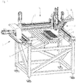
- Fig. 1 shows a device 1 for loading, which is arranged on a gantry crane-like carrier 2.
- a cell carrier 4 with several receiving spaces for round cells 5 is arranged on a table 6 below the beam 3 of the carrier 2.
- a multi-axis robot (not shown) can be provided which moves the placement head 7 of the device 1 into the correct position in each case.
- the Table 6, on which the cell carrier 4 for round cells 5 is arranged is horizontally adjustable in the manner of a cross table, or that a workpiece transfer system is provided.
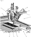
- Fig. 2 shows the placement head 7 with a magazine 8 containing round cells 5 in greater detail.
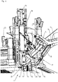
- Fig. 3 shows a detail of the assembly head 7 with the magazine 8 and a separating device 9, a device 10 for pivoting (rotating) round cells 5 in the correct polarity and the loading channel 11 in which the round cells 5 when they have been aligned in the correct polarity , be moved into it.
- Fig. 4 and 5 show in more detail the device 10 for pivoting the round cells 5 into the correct polarity and a transfer tray 12 with which the round cells 5 aligned in the correct polarity are moved into the loading channel 11 of the placement head 7.
- Fig. 6 shows a detail of the device 1 for equipping cell carriers 4 with round cells 5 in a different view.
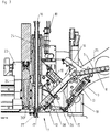
- Fig. 7 shows in section the separating device 9, the device 10 for pivoting (aligning) the round cells 5 in the correct polarity, the loading mechanism with transfer tray 12 and, as a setting mechanism, the placement head 7 with loading channel 11.
- the magazine 8 for lithium-ion round cells 5 of the device 1 is, for example, a flat magazine or a magazine with several receptacles or a magazine in which round cells simply lie on top of one another.
- the type of magazine in which round cells 5 are kept in stock is largely arbitrary, so that the magazine can be designed in different embodiments.
- the embodiment shown as a (flat) magazine 8 is not mandatory.
- the magazine can be designed as a FIFO magazine (“first in first out” magazine) or as a magazine with a chaotic system.
- the separating device 9 On the delivery side of the magazine 8, the separating device 9 is provided, which is designed as a rotary star 13 in the exemplary embodiment shown, the rotary star 13, for example, having a length which corresponds approximately to the length of round cells 5. With the aid of the separating device 9, a round cell 5 is removed from the magazine 8 and moved to the device 10 in which the round cells 5 are aligned (pivoted) in the correct polarity.
- An arrangement 14 for determining the polarity of the round cells 5 is provided in front of the device 10. With the aid of the arrangement 14, it is determined which position the positive pole and the negative pole of the round cell 5 which has just been isolated have.
- a sensor 28, arranged for example on a bridge 26, can be provided downstream of the device 10, with the aid of which it is determined whether round cells 5 have arrived correctly in the loading mechanism provided after the device 10.
- the separating device 9 also prevents more than one round cell 5 from being removed from the magazine 8.
- the separation of the round cells 5 can also be configured differently than with a rotary star 13. It is only essential that a round cell 5 is removed from the magazine 8, first from the arrangement 14 for determining the polarity and then the downstream device 10 for pivoting (rotating) round cells 5 into the correct orientation (correct polarity) is fed.
- the device 10 for pivoting round cells 5 into the correct orientation is designed in the embodiment shown as an arrangement with two pins 15 that can be pushed back and forth.
- both pins 15 of the device 10 are advanced, so that a round cell 5 coming (rolling towards) the separating device 9 comes into contact with both pins 5.
- the round cell 5 pivots clockwise by about 90 ° when it moves past the pin 15. Similarly, a counterclockwise pivoting occurs when the other (in Fig. 3 "front” pin 15) is in its operative position. In this way it is achieved that the round cell 5 is aligned in the downstream transfer shell 12 in such a way that it has the correct polarity, that is to say, with the desired pole facing downwards.
- the loading mechanism is designed as a tiltable (pivotable), approximately trough-shaped transfer tray 12 which, with the aid of a drive 19 (pivot mechanism), is moved from the into the Fig. 3 , 6th and 7th
- the position shown (each with a round cell 5) can be pivoted into a position in which the round cell 5 is aligned essentially vertically and is received in the loading channel 11 of the placement head 7.
- a guide 27, open on one side in the direction of the transfer tray 12 can be provided for round cells 5, if necessary, in order to carry out complex assemblies in particular (inserting round cells 5 into a cell carrier 4). to support ( Fig.
- the guide 27 can be designed, for example, as a longitudinally divided tube, the open side of which points towards the transfer tray 12 and the inner surface of which corresponds to the outer contour of a round cell.
- the guide 27 for round cells 5 in its basic position at the lower end of the loading channel 11 is arranged opposite the pivoted transfer tray 12.
- the guide 27 for round cells 5 is advantageous because round cells 5 are stabilized during the setting process carried out with the aid of the setting tube 16. As a result, no problems arise even with a high packing density in the cell carrier 4 and small distances between round cells 5.
- the guide 27 for round cells 5 can be moved with the aid of a drive 30 (similar to the drive 23 for the setting tube 16).
- the guide 27 for round cells 5 can be subjected to negative pressure via a connection 29 in order to hold round cells 5 in the guide 27 and to guide them precisely.
- a round cell 5 has been held by the setting tube 16 and has reached the cell carrier 4 supported by the guide 27, only the setting tube 16 with the round cell 5 is moved on, the round cell 5 sliding along the guide 27 ( Fig. 9 ).
- both the vacuum applied to the suction head 17 and to the guide 27 is canceled.
- the setting tube 16 and the guide 27 are back in their in the Fig. 7 and 8th The basic position shown has been moved back and are ready to accommodate a further round cell 5.
- the guide 27 for round cells 5 can be equipped with sensors so that the current position of round cells 5 is recorded in order to avoid collisions with round cells 5 that are already in place.
- Perpendicularly aligned round cells 5 are located at the lower end of the loading channel 11, in which - adjustable in an essentially vertical direction - a tubular setting tube 16 is provided.
- the setting tube 16 has at its lower end a suction head 17, which can be acted upon by a vacuum source 18 with a vacuum via the upper end of the setting tube 16.
- the setting tube 16 with its suction head 17 is assigned a drive 23 which is arranged on the fitting head 7 and is opposite the setting tube 16 in relation to the direction in which round cells 5 are fed from the transfer tray 12.
- the drive 23 has a linear motor designed as a pneumatic cylinder, which is coupled to the setting tube 16 in the area of the end of the setting tube 16 opposite the suction head 17 (cf. Fig. 7 ).
- the hollow set tube 16 is in the placement head 7 in guides 24 (cf. Fig. 7 ) and connected at its upper end to the vacuum source, which acts on the suction head 17 with negative pressure.
- the round cell 5 is held on the suction head 17 of the setting tube 16 by negative pressure until the round cell 5 has safely reached the defined end position in the cell carrier 4.
- the negative pressure applied to the suction head 17 is released and, if necessary, the drinking head 17 is pressurized with compressed air in order to safely release the round cell 5 held by it.
- the setting tube 16 is moved back up to its starting position so that the loading channel 11 is freely accessible again and another round cell 5 can be introduced into the loading channel 11 from the transfer tray 12.
- the correct position in which a round cell 5 is inserted into a receiving space in the cell carrier 4 is achieved by moving the device 1 by actuating the gantry crane-like carrier 2 and / or the beam 3 ( Fig. 1 ) achieved.
- the transfer tray 12 is pivotably arranged in the lower region of the equipping head 7 with the channel in which the setting tube 16 can be moved up and down.
- the pivot mechanism 19 for the transfer tray 12 comprises a linear motor 20, for example a pneumatic cylinder or an electric drive, an essentially triangular or round disc pivotable about an axis fixed to the frame, and a connecting rod 22 which controls the control arm 21 with the transfer shell 12 couples.
- the arrangement 14 is provided with which the polarity of round cells 5 is determined, whereby the arrangement 14 can also check the proper function of round cells 5 at the same time.
- the arrangement 14 controls the device 10 for pivoting round cells 5 according to the polarity of the round cells 5 coming from the separating device 9 determined by the arrangement 14, so that the correct pivoting process (clockwise or counterclockwise) is carried out. For example, the arrangement 14 controls the withdrawal of the correct pin 15 of the device 10.
- the device for pivoting round cells 5 can be designed as a trough (channel) into which an isolated round cell 5 is inserted (or slides into). The tub is then swiveled either in one direction or in the other direction, for example with the help of an electric or pneumatic drive, to the round cell 5 for the To align the sliding in the transfer tray 12 so that the desired pole points upwards, that is to say the round cell 5 is fed to the equipping head 7 aligned with the specified (“correct”) polarity. If the device 10 for pivoting round cells 5 is designed as a trough (or as a channel), it can be advantageous to combine the trough with the arrangement 14 for determining the polarity of the round cell 5 accommodated in the trough.
- a receptacle 25 is provided for the magazine 8 for round cells 5, which can be fixed to the device 1 in different angular positions.
- the transfer tray 12 In order to prevent a round cell 5 from coming into electrically conductive contact with the transfer tray 12 while it slides to the transfer tray 12 and is moved by this to the lower end of the assembly head 7, the transfer tray 12, or at least its inner part, is where the Round cell 5 rests, made of electrically non-conductive material (insulating material).
- One advantage of the described embodiment of the equipping head 7 is, inter alia, that it allows the equipping device 1 to be adapted to different shapes and sizes of round cells 5.
- a device 1 for equipping carriers 4 with round cells for example lithium-ion round cells 5
- round cells 5 are individually removed from the magazine 8, then pivoted to align them with the correct polarity, whereupon the round cells 5 are detected with the correct polarity and placed in the carrier 4 for round cells 5.
Landscapes
- Engineering & Computer Science (AREA)
- Manufacturing & Machinery (AREA)
- Chemical & Material Sciences (AREA)
- Chemical Kinetics & Catalysis (AREA)
- Electrochemistry (AREA)
- General Chemical & Material Sciences (AREA)
- Robotics (AREA)
- Mechanical Engineering (AREA)
- Apparatus Associated With Microorganisms And Enzymes (AREA)
- Sampling And Sample Adjustment (AREA)
Applications Claiming Priority (1)
| Application Number | Priority Date | Filing Date | Title |
|---|---|---|---|
| ATA50295/2020A AT523699B1 (de) | 2020-04-07 | 2020-04-07 | Verfahren und Vorrichtung zum Bestücken von Trägern mit Rundzellen |
Publications (1)
| Publication Number | Publication Date |
|---|---|
| EP3893307A1 true EP3893307A1 (fr) | 2021-10-13 |
Family
ID=75362521
Family Applications (1)
| Application Number | Title | Priority Date | Filing Date |
|---|---|---|---|
| EP21166742.3A Withdrawn EP3893307A1 (fr) | 2020-04-07 | 2021-04-01 | Procédé et dispositif d'équipement des supports des cellules rondes |
Country Status (2)
| Country | Link |
|---|---|
| EP (1) | EP3893307A1 (fr) |
| AT (1) | AT523699B1 (fr) |
Cited By (3)
| Publication number | Priority date | Publication date | Assignee | Title |
|---|---|---|---|---|
| CN115241581A (zh) * | 2022-07-11 | 2022-10-25 | 盐城国投中科新能源科技有限公司 | 一种电池模组电芯的旋转配比装置 |
| CN115352868A (zh) * | 2022-08-02 | 2022-11-18 | 武汉逸飞激光股份有限公司 | 电芯暂存装置 |
| WO2024153559A1 (fr) * | 2023-01-18 | 2024-07-25 | thyssenkrupp Automation Engineering GmbH | Dispositif, système et procédé pour le positionnement d'éléments de batterie |
Citations (4)
| Publication number | Priority date | Publication date | Assignee | Title |
|---|---|---|---|---|
| CN104300162A (zh) | 2014-09-12 | 2015-01-21 | 南京信息工程大学 | 一种电池组自动装配设备 |
| CN204991870U (zh) * | 2015-08-18 | 2016-01-20 | 上海莱爵特实业有限公司 | 一种自动化电池组组装设备 |
| CN108899589A (zh) * | 2018-07-13 | 2018-11-27 | 广东六缘智能装备科技有限公司 | 一种锂电池组自动组装机 |
| CN106025328B (zh) * | 2016-07-25 | 2019-01-11 | 上海南库新能源技术有限公司 | 一种自动装电芯装置 |
Family Cites Families (2)
| Publication number | Priority date | Publication date | Assignee | Title |
|---|---|---|---|---|
| KR100673290B1 (ko) * | 2005-04-14 | 2007-01-24 | 경북대학교 산학협력단 | 배터리의 섭취 기능을 가진 로봇 |
| CN107819134B (zh) * | 2017-09-27 | 2020-09-01 | 丁琛琦 | 新能源电池模组装配线 |
-
2020
- 2020-04-07 AT ATA50295/2020A patent/AT523699B1/de active
-
2021
- 2021-04-01 EP EP21166742.3A patent/EP3893307A1/fr not_active Withdrawn
Patent Citations (4)
| Publication number | Priority date | Publication date | Assignee | Title |
|---|---|---|---|---|
| CN104300162A (zh) | 2014-09-12 | 2015-01-21 | 南京信息工程大学 | 一种电池组自动装配设备 |
| CN204991870U (zh) * | 2015-08-18 | 2016-01-20 | 上海莱爵特实业有限公司 | 一种自动化电池组组装设备 |
| CN106025328B (zh) * | 2016-07-25 | 2019-01-11 | 上海南库新能源技术有限公司 | 一种自动装电芯装置 |
| CN108899589A (zh) * | 2018-07-13 | 2018-11-27 | 广东六缘智能装备科技有限公司 | 一种锂电池组自动组装机 |
Cited By (4)
| Publication number | Priority date | Publication date | Assignee | Title |
|---|---|---|---|---|
| CN115241581A (zh) * | 2022-07-11 | 2022-10-25 | 盐城国投中科新能源科技有限公司 | 一种电池模组电芯的旋转配比装置 |
| CN115241581B (zh) * | 2022-07-11 | 2023-11-17 | 盐城国投中科新能源科技有限公司 | 一种电池模组电芯的旋转配比装置 |
| CN115352868A (zh) * | 2022-08-02 | 2022-11-18 | 武汉逸飞激光股份有限公司 | 电芯暂存装置 |
| WO2024153559A1 (fr) * | 2023-01-18 | 2024-07-25 | thyssenkrupp Automation Engineering GmbH | Dispositif, système et procédé pour le positionnement d'éléments de batterie |
Also Published As
| Publication number | Publication date |
|---|---|
| AT523699B1 (de) | 2022-04-15 |
| AT523699A1 (de) | 2021-10-15 |
Similar Documents
| Publication | Publication Date | Title |
|---|---|---|
| EP3893307A1 (fr) | Procédé et dispositif d'équipement des supports des cellules rondes | |
| AT511078B1 (de) | Fertigungsanlage mit einem werkzeugwechselsystem | |
| DE69504359T2 (de) | Robotereinrichtung | |
| DE2444124C3 (de) | Zusatzeinrichtung zum automatischen Be- und/oder Entladen von Werkzeugmaschinen | |
| EP3157804A1 (fr) | Plaque de réception segmentée pour une pièce à usiner | |
| DE19621658C2 (de) | Bearbeitungsmaschine für plattenförmige Werkstücke, insbesondere zur Erzeugung von gebogenen Rändern an Blechteilen | |
| DE102010003085A1 (de) | Vorrichtung und Verfahren zum Zuführen und Befestigen von Ausgleichselementen für den Unwuchtausgleich, insbesondere in einer Auswuchtmaschine | |
| EP2130445B9 (fr) | Dispositif et procédé de vidage successif de récipients remplis de produits en forme de tiges | |
| EP0218949B1 (fr) | Procédé et dispositif pour alimenter un bobinoir avec des tubes de bobine | |
| EP1022821B1 (fr) | Méthode et dispositif pour appliquer des manchons | |
| EP1388614A2 (fr) | Procédé et dispositif pour la prise et le transport de poteaux pour glissières de sécurité | |
| EP3956671A1 (fr) | Procédé et dispositif pour le balayage de lames porte-objets | |
| EP1798174B1 (fr) | Dispositif et méthode pour la manipulation de bobines dans une cellule d'automatisation et une cellule d'automatisation | |
| EP2100834B1 (fr) | Dispositif de manipulation destiné au transport de récipients remplis et/ou devant être remplis d'articles | |
| DE102018109706B4 (de) | Bestückungsstation zur Bestückung einer Rotoreinheit oder eines Hilfswerkzeugs mit Magnetelementen und Verfahren zum Bestücken einer ringförmigen Rotoreinheit für einen Elektromotor mit Magnetelementen | |
| EP1990129B1 (fr) | Dispositif d'alimentation et procédé destiné à alimenter un dispositif de traitement d'une machine-outil | |
| WO2008080811A2 (fr) | Système de fabrication d'éléments structurels, notamment d'éléments de carrosserie de véhicules automobiles | |
| EP1733821B1 (fr) | Dispositif de sélection et de pose de rivets | |
| WO2022242833A1 (fr) | Dispositif de placement, dispositif de montage et procédé associé | |
| DE102021109037A1 (de) | Beladevorrichtung zum wechseln von werkzeug eines werkzeugmagazins an einer werkzeugmaschine und verfahren zum wechseln von werkzeug an einem werkzeugmagazin | |
| EP1557382B1 (fr) | Dispositif pour le prélèvement de palettes vides | |
| DE102016012504A1 (de) | Vorrichtung zur positionsrichtigen Anordnung eines Bauteils auf einer Fläche | |
| EP0983949A1 (fr) | Méthode et dispositif pour l'alimentation des profilés creux vers une machine à plier dans la fabrication de vitres isolants | |
| EP1651383B1 (fr) | Dispositif de changement d'outil pour une machine-outil et procede pour le changement d'outil sur une machine-outil | |
| DE102013110058A1 (de) | Werkzeugmaschine mit Handhabungseinrichtung und Verfahren zum Beladen und Entladen einer Werkzeugmaschine |
Legal Events
| Date | Code | Title | Description |
|---|---|---|---|
| PUAI | Public reference made under article 153(3) epc to a published international application that has entered the european phase |
Free format text: ORIGINAL CODE: 0009012 |
|
| STAA | Information on the status of an ep patent application or granted ep patent |
Free format text: STATUS: THE APPLICATION HAS BEEN PUBLISHED |
|
| AK | Designated contracting states |
Kind code of ref document: A1 Designated state(s): AL AT BE BG CH CY CZ DE DK EE ES FI FR GB GR HR HU IE IS IT LI LT LU LV MC MK MT NL NO PL PT RO RS SE SI SK SM TR |
|
| STAA | Information on the status of an ep patent application or granted ep patent |
Free format text: STATUS: THE APPLICATION IS DEEMED TO BE WITHDRAWN |
|
| 18D | Application deemed to be withdrawn |
Effective date: 20220414 |