EP3893638B1 - Deckel für einen behälter mit axialen verriegelungselementen an einem öffnungsrand des behälters - Google Patents
Deckel für einen behälter mit axialen verriegelungselementen an einem öffnungsrand des behälters Download PDFInfo
- Publication number
- EP3893638B1 EP3893638B1 EP20710247.6A EP20710247A EP3893638B1 EP 3893638 B1 EP3893638 B1 EP 3893638B1 EP 20710247 A EP20710247 A EP 20710247A EP 3893638 B1 EP3893638 B1 EP 3893638B1
- Authority
- EP
- European Patent Office
- Prior art keywords
- cover
- blocking
- cover part
- locking
- angular
- Prior art date
- Legal status (The legal status is an assumption and is not a legal conclusion. Google has not performed a legal analysis and makes no representation as to the accuracy of the status listed.)
- Active
Links
Images



Classifications
-
- A—HUMAN NECESSITIES
- A01—AGRICULTURE; FORESTRY; ANIMAL HUSBANDRY; HUNTING; TRAPPING; FISHING
- A01M—CATCHING, TRAPPING OR SCARING OF ANIMALS; APPARATUS FOR THE DESTRUCTION OF NOXIOUS ANIMALS OR NOXIOUS PLANTS
- A01M7/00—Special adaptations or arrangements of liquid-spraying apparatus for purposes covered by this subclass
- A01M7/0082—Undercarriages, frames, mountings, couplings, tanks
- A01M7/0085—Tanks
-
- A—HUMAN NECESSITIES
- A01—AGRICULTURE; FORESTRY; ANIMAL HUSBANDRY; HUNTING; TRAPPING; FISHING
- A01C—PLANTING; SOWING; FERTILISING
- A01C23/00—Distributing devices specially adapted for liquid manure or other fertilising liquid, including ammonia, e.g. transport tanks or sprinkling wagons
- A01C23/008—Tanks, chassis or related parts
Definitions
- the invention relates to a cover for a tank, in particular intended to contain a phytosanitary product or a liquid fertilizer, a sub-assembly comprising a collar and such a cover, as well as an assembly comprising a tank and such a sub-assembly or such a lid.
- This tank has an opening which is defined by an opening rim and which is closed by a cover comprising, in a conventional manner, a first and a second cover part pivotally mounted on the first cover part about a pivot axis in an axial direction, between a first angular unlocking position and a second angular locking position in which the lid is locked axially on the opening edge of the tank.
- the opening edge of the tank is provided with an internal thread which cooperates, after the pivoting of the second part of the cover up to the second angular blocking position, with a outer thread of the second cover part.
- the phytosanitary product or the liquid fertilizer contained in the tank tends to deform the tank, in particular at the level of its opening which becomes oval .
- the opening rim of the tank then presses the second part of the cover, generally towards the pivot axis, often until the cover is ejected, which thus frees the opening of the tank.
- GB 744 001 A describes a cover for a tank according to the prior art.
- the invention proposes a cover for a tank comprising a first cover part, a second cover part pivotally mounted on the first cover part between a first angular unlocking position and a second angular locking position, as well as locking members movable relative to the first and to the second lid part and intended to cooperate with a radially outer surface of an opening rim of the tank to axially lock the lid relative to the tank, when the second cover part occupies the second angular locking position.
- the invention also relates to a sub-assembly for a tank, intended to contain a phytosanitary product or a liquid fertilizer, comprising a lid as previously described, and an annular flange, extending around the pivot axis and intended to be fixed at the opening edge of the tank, the blocking members cooperating with the radially outer surface of the opening edge of the tank via the flange, when the blocking members occupy their blocking position.
- the invention also relates to an assembly comprising a tank intended to contain a phytosanitary product or a liquid fertilizer as well as a lid as previously described or a subassembly as previously described.
- the figure 1 shows a sub-assembly for tank 100, for example intended to contain a phytosanitary product or a liquid fertilizer, comprising a cover 10 and a collar 200 which will be described in more detail later in the description.
- the figures 2 to 6 also show an assembly comprising the tank 100, the flange 200 and the cover 10 closing off an opening 101 of the tank 100 defined by an opening rim 102.
- the tank 100 is for example intended to equip an agricultural machine (not shown).
- the cover 10 comprises a first cover part 11, a second cover part 12 and a plurality of locking members 13.
- the second cover part 12 is pivotally mounted on the first cover part 11, around a pivot axis 14, between a first angular unlocking position and a second angular locking position in which the cover 10 is locked axially on the opening edge 102 of the tank 100 which extends around the pivot axis 14.
- the second lid part 12 thus pivots from the first angular unlocking position to the second angular locking position in a first pivoting direction P1 ( figure 2 and 7 ), and from the second angular locking position to the first angular unlocking position in a second direction of pivoting P2 ( figure 3 and 8 ) opposite to the first direction of pivoting P1.
- the cover 10 in the second angular locking position, the axial locking of the cover 10 on the opening rim 102 of the tank 100 retains the cover 10 on the tank 100 and thus keeps the tank 100 closed.
- the cover 10 in the first angular locking position, in the absence of axial locking of the cover 10 on the opening edge 102 of the tank 100, the cover 10 can release the opening 101 of the tank 100, the tank 100 thus being able to be open.
- the axial direction is the direction of the pivot axis 14.
- the radial direction R is at all points a direction orthogonal to the pivot axis 14 and passing through the latter, and the circumferential direction is at any point a direction orthogonal to the radial direction and to the pivot axis 14.
- the axial direction is for example vertical, the radial and circumferential directions thus being horizontal.
- the first cover part 11 forms for example a lower part of the cover 10, while the second cover part 12 forms an upper part of the cover 10.
- the locking members 13 are distributed around the pivot axis 14.
- Each of the locking members 13 is still mounted to move relative to the first and second cover parts 11, 12 between an unlocking position ( figure 2 , 4 and 7 ) and a blocking position ( figure 3 , 5 and 8 ) in which the locking member 13 is radially closer to the pivot axis 14 than in the unlocked position and in which it cooperates with a radially outer surface 103 of the opening rim 102 of the tank 100 to axially lock the lid 10 relative to tank 100.
- the cover 10 is also designed so that each of the locking members 13 is moved, relative to the first and second cover parts 11, 12 from its unlocking position to its locking position, when the second cover part 12 pivots from the first angular unlocking position to the second angular locking position. Similarly, when the second cover part 12 pivots from the second angular locking position to the first angular unlocking position, each of the locking members 13 is moved from its locking position to its unlocking position.
- the second cover part 12 occupies the second angular blocking position and the blocking members 13 occupy their blocking position, the latter cooperate with the radially outer surface 103 of the tank 100 ( figure 3 , 5 and 8 ).
- the opening edge 102 of the tank 100 presses the second part of the lid 12, in a direction opposite to the pivot axis 14, so that it retains the cover 10 rather than ejecting it. The risks of accidental opening of the tank 100 are thus reduced.
- the locking members 13 are for example axially interposed between the first and second cover parts 11, 12, so as to be housed in an interior space of the cover 10.
- the cover 10 comprises for example a movement transformation mechanism 15, 23 designed to transform the pivoting of the second cover part 12, relative to the first cover part 11, from the first angular unlocking position to the second angular position locking, in movement of each of the locking members 13, relative to the first cover part 11, from its unlocking position to its locking position.
- a movement transformation mechanism 15, 23 designed to transform the pivoting of the second cover part 12, relative to the first cover part 11, from the first angular unlocking position to the second angular position locking, in movement of each of the locking members 13, relative to the first cover part 11, from its unlocking position to its locking position.
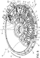
- figure 7 and 8 show the motion transformation mechanism 15, 23 in more detail.
- figure 9 shows the kinematics of the motion transformation mechanism 15, 23.
- the motion transformation mechanism 15, 23 comprises at least a first drive member 15 carried by the second cover part 12 and cooperating with the locking members 13 or each with one or more of the locking members 13.
- the first drive member(s) 15 are also designed to drive the blocking member(s) 13 with which it cooperates, moving relative to the first cover part 11, from their unlocking position to their blocking position, when the second cover part 12 pivots from the first angular unlocking position to the second angular locking position.
- the first drive member(s) 15 carried by the second cover part 12 thus provide the locking members 13 with an alternating or back-and-forth movement, with respect to the first cover part 11, between their position of release and their locking position.
- the motion transformation mechanism 15, 23 will be described as comprising several first drive members 15 each cooperating with one of the blocking members 13, without this being limiting.
- the movement transformation mechanism 15, 23 comprises only a single first drive member 15 cooperating with all of the locking members 13 and in the case where the movement transformation mechanism 15, 23 comprises several first drive members 15 each cooperating with several locking members 13.
- the first drive members 15 each form, for example, a cam cooperating, in particular by sliding, with one of the locking members 13 thus itself forming a cam follower.
- each of the first drive members 15 may have the shape of a first groove extending along an extension line 17, included in a plane (not shown) orthogonal to the pivot axis 14.
- the line extension 17 can be curved or straight, as will be described in more detail later in the description.
- Each first groove 15 comprises at least one first drive or cam surface 18, 19, in particular two, via which the locking members 13 are driven in displacement, relative to the first cover part 11, between their unlocking position and their locking position, when the second cover part 12 pivots between the first angular unlocking position and the second angular locking position.
- the first drive surfaces 18, 19 are generally parallel to each other and to the extension line 17 and are oriented opposite each other.
- the first drive surfaces 18, 19 are for example also oriented parallel to the pivot axis 14.
- the locking members 13 are also each mounted sliding, along the line of extension 17, on the second cover part 12, via the first drive surfaces 18, 19.
- the locking members 13 are each mounted rolling on the first drive surfaces 18, 19, around a rolling axis parallel to the pivot axis 14.
- Each of the first grooves 15 extends further along the line of extension 17 between a first end 20 towards which the locking members 13 move, when the second cover part 12 pivots towards the first angular unlocking position, and a second opposite end 21, towards which the blocking members 13 move, when the second cover part 12 pivots towards the second angular blocking position.
- the second end 21 of the first grooves 15 is radially closer to the pivot axis 14 than the first end 20, so as to ensure the radial offset of the locking members 13 between their unlocking position and their position. blockage.
- the second end 21 of the first grooves 15 is circumferentially separated from the first end 20 in the first direction of pivoting P1, so as to allow the pivoting of the second cover part 12, relative to the locking members 13, between the first angular unlocking position and the second angular locking position.
- Each of the first grooves 15 is also shifted radially and circumferentially, from its first end 20 towards its second end 21, in a progressive manner, so as to move the locking members 13 between their unlocking position and their locking position, without locking. .
- each of the first grooves 15 has for example the shape of a spiral.
- the first grooves 15 allow the second cover part 12 to pivot over a larger angular sector, in particular compared to a variant (not shown) with first rectilinear grooves.
- the first grooves 15 thus allow a greater amplitude of pivoting for the second cover part 12.
- Each first groove 15 extends for example along its extension line 17, between its first and second ends 20, 21, over an angular sector between 65° and 75°, in particular equal to 69°.
- the locking members 13 can also be designed to come into abutment against the second end 21 of the first grooves 15, when the second cover part 12 pivots towards the second angular locking position ( figure 8 ), and to come into abutment against the first end 20 of the first grooves 15, when the first cover part 12 pivots towards the first angular locking position ( figure 7 ).
- a radial offset between the first and second ends 20, 21 of the first grooves 15 is for example between 7 and 10 mm, in particular equal to 8.5 mm.
- the blocking members 13 themselves move radially by 7 to 10mm, in particular by 8.5mm.
- the first drive surfaces 18, 19 of each of the first grooves 15 are for example closer to each other at their second end 21 than at their first end 20 and between their first and second ends 20, 21.
- the first grooves 15 are thus closer together at their second end 21 than at their first end 20 and between their first and second ends 20, 21.
- first grooves 15 provide for an assembly with play of the locking members 13 at the level of their first end 20 and between their first and second ends 20, 21, and an adjusted or even tight mounting of the locking members 13 at the level from their second end 21.
- the friction between the locking members 13 and the first drive surfaces 18, 19 is increased at the level of the second end 21 of the first grooves 15, so as to prevent the locking members 13 from moving into the locking position.
- the friction is reduced at the level of the first end 21 and between the first and second ends 20, 21 in order to reduce the torque necessary for the pivoting of the second cover part 12.
- the blocking members 13 slide for example along the first grooves 15 by means of bosses (not shown) carried by the blocking members 13, in particular machined on the blocking members 13.
- the bosses cooperate for example with the first surfaces drive 18, 19.
- the bosses extend for example radially.
- the first two grooves 15 with which each pair of circumferentially adjacent locking members 13 cooperate are, for example, offset radially from one another.
- the first grooves 15 each cooperate for example with one of the locking members 13 via a pin 22 oriented axially and projecting from the locking member 13.
- Each locking member 13 thus carries a pin 22 cooperating , in particular by sliding, with the first drive surfaces 18, 19 of one of the first grooves 15.
- the pins 22 carry, for example, the bosses.
- the pins 22 are carried by the second cover part 12, while the first grooves 15 are carried by the locking members 13.
- the motion transformation mechanism 15, 23 comprises a single first drive member 15 in the form of a part integral in pivoting with the second cover part 12 around the pivot axis 14.
- This part comprises several cam surfaces, parallel to the pivot axis 14 and distributed around the pivot axis 14.
- the cam surfaces are oriented in a direction opposite to the pivot axis 14.
- Each of these cam surfaces also cooperate, in particular by sliding, with one of the locking members 13 thus forming a cam follower.
- the lid 10 further comprises one or more elastic return members mounted between the blocking members 13 and the first cover part 11 and designed to return the blocking members 13 to their blocking position.
- Each of the blocking members 13 is for example mounted to slide, with respect to the first cover part 11, between its unlocking position and its blocking position, along a line of sliding 16, the blocking members 13 thus being driven in sliding by the first drive members 15.
- Each of the locking members 13 thus slides relative to the first cover part 11, from its unlocking position to its locking position, in a first direction of sliding C1, and from its position locking to its unlocking position in a second direction of sliding C2 opposite to the first direction of sliding C1.
- Each of the sliding lines 16 is for example included in a plane (not shown) orthogonal to the pivot axis 14.
- Each of the sliding lines 16 is for example rectilinear.
- Each of the sliding lines 16 thus forms a radial sliding axis, when it is rectilinear and included in a plane orthogonal to the pivot axis 14.
- the locking members 13 each slide radially, with respect to the first cover part 11, between their unlocked position and their locked position.
- each of the sliding lines 16 is curved.
- the first cover part 11 carries, for example, guide members 23 each designed to guide one of the blocking members 13 in displacement, in particular in sliding along the sliding line 16, with respect to the first cover part 11, between its unlocking position and its locking position.
- each of the guide members 23 has for example the shape of a second groove extending along the sliding line 16 and housing one of the locking members 13, so as to guide it in sliding between its position of release and its locking position.
- the second grooves 23 each extend, for example, along the sliding line 16 between a first end 231 and an opposite second end 232, which is radially closer to the pivot axis 14 than the first end 231 ( figure 1 ).
- the locking members 13 each project radially, for example, in a direction opposite to the pivot axis 14, from the first end 231 of the second groove 23 in which it is housed ( figure 2 and 7 ). This allows the blocking members 13 to cooperate with the radially outer surface 103 of the opening rim 102 of the tank 100 to axially block the lid 10 with respect to the tank 100, when they occupy their blocking position.
- the collar 200 is for example annular and extends around the pivot axis 14.
- the collar 200 is also fixed to the rim of the opening 102 of the tank 100, the locking members 13 further cooperating with the surface radially outside 103 of the opening rim 102 of the tank 100 via the flange 200, when they occupy their locking position.
- the flange 200 itself has a radially outer surface 201 with which the locking members 13 cooperate in the locking position ( figure 5 ).
- the cover 10 is for example hinged on the collar 200 around a hinge axis 202, substantially perpendicular to the pivot axis 14, between an open position of the cover 10 and a closed position of the cover 10 in which the lid 10 closes the opening 101 of the tank 100 ( figures 2, 3 , 7 and 8 ).
- the cover 10 can be articulated on the collar 200 via the first cover part 11, while the second cover part 12 is held axially on the first cover part 11.
- cover sectors 24 are for example provided ( figures 1 to 8 ). These cover sectors 24 are mounted integral with the first cover part 11, in particular by screwing, and each comprise a retaining portion 25 arranged axially opposite the second cover part 12, and located axially on an opposite side of the first cover part 11, with respect to the second cover part 12 ( figure 4 and 6 ). The cover sectors 24 are for example attached to the periphery of the first and second cover parts 11, 12.
- Crimp nuts are also provided, for example, to fix the collar 200 to the rim of the opening 102 of the tank 100.
- Such nuts have a resistance to tearing greater than that of standard rivets or screws.
- the collar 200 and the cover 10 can be torn off from the tank 100 with more difficulty, in particular when the agricultural machine brakes or takes a turn at high speed and the phytosanitary product or the liquid fertilizer contained in the tank 100 makes waves which tend to eject the collar 200 and the cover 10.
- such nuts allow non-destructive dismantling of the sub-assembly comprising the flange 200 and the cover 10.
- These crimp nuts are for example made of stainless steel.
- the blocking members 13 each comprise for example a body 26 provided with a claw 27 cooperating with the radially outer surface 103 of the opening rim 102 of the tank 100, in particular with the radially outer surface 201 of the collar 200, to block axially the lid 10 relative to the tank 100, when the locking member 13 occupies its locking position ( figures 4 and 5 ).
- the claw 27 of each of the locking members 13 is for example designed to be housed in a notch 203 hollowing out, generally radially, the radially outer surface 103 of the opening rim 102 of the tank 100, in particular the radially outer surface 201 of the collar 200, when the locking member 13 occupies its locking position, and to release the notch 203, when the locking member 13 occupies its unlocking position ( figure 1 , 4 and 5 ).
- the radially outer surface 103, 201 of the tank 100 or of the flange 200 is for example provided with a plurality of notches 203 distributed around the pivot axis 14, each of the notches 203 being designed to accommodate the claw 27 d one or more blocking members 13, when the blocking member 13 occupies its blocking position.
- the radially outer surface 103, 201 of the tank 100 or of the flange 200 is provided with a single notch designed to accommodate the claw 27 of all the locking members 13, when the locking members 13 occupy their blocking position.
- each of the locking members 13 has, for example, a first portion 29 extending generally axially from the body 26 of the locking member 13 and a second portion 30 extending in the extension of the first portion 29, generally radially towards the pivot axis 14 and at a distance from the body 26.
- the claw 27 is thus folded up or even folded down on the body 26.
- the claw 27 of each of the blocking members 13 extends for example over an angular sector between 20 and 60° inclusive, in particular equal to 30°.
- the claws 27 of the blocking members 13 cover, for example together or even in aggregate, an angular sector greater than 180°, in particular equal to 210°.
- the lid 10 comprises for example here seven locking members 13 each comprising a claw 27 covering an angular sector of 30°, the claws 27 thus covering in aggregate an angular sector of 210°.
- the remaining angular sector, which corresponds to 150°, is for example used by the second grooves 23 (105°), as well as by the articulation of the cover 10 on the flange 200 (45°).
- the cover 10 may also comprise an annular seal 28 housed in a groove hollowed out, generally radially, in the first part of the cover 11, and designed to cooperate with a radially inner surface 204 of the flange 200 ( figure 4 and 6 ), when the cover 10 is in the closed position.
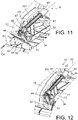
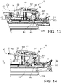
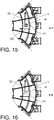
- the cover 10 for example also comprises a locking mechanism 31, 32, 33, 41 shown in detail in figures 10 to 16 .
- the locking mechanism 31, 32, 33, 41 is also visible on the figure 7 and 8 .
- the locking mechanism 31, 32, 33, 41 is designed to automatically lock the pivoting of the second cover part 12, relative to the first cover part 11, in the second direction of pivoting P2 going from the second angular position of locking towards the first angular unlocking position, when the second cover part 12 reaches the second angular locking position.
- the locking mechanism 31, 32, 33, 41 therefore automatically locks the second cover part 12 in the second angular locking position.
- the locking mechanism 31, 32, 33 , 41 prevents the second cover part 12 from pivot to the first angular unlocking position and therefore the cover 10 to unlock axially inadvertently.
- the locking mechanism 31, 32, 33, 41 engages automatically, when the second cover part 12 reaches the second locking angular position, so that the locking of the second cover part 12 is more reliable and safer than a manual lock.
- the locking of the second cover part 12 no longer depends on the intensity of a locking torque to be applied to the second cover part 12, as is for example the case in the prior art to jam the outer thread of the lid 10 with the inner thread of the tank 100 with each other.
- the locking mechanism 31, 32, 33, 41 comprises for example a locking member 31, a second drive member 32 and an elastic return member 33.
- the locking member 31 is movably mounted on one of the first and second cover parts 11, 12 between a rest position ( figure 10 , 12 , 13 and 15 ) and a constrained position ( figure 11 , 14 and 16 ) wherein the elastic return member 33 recalls the locking member 31 in movement towards the rest position.
- the second drive member 32 is integral with the other of the first and second cover parts 12, 11.
- the locking member 31 will be described movably mounted on the second cover part 12, and the second drive member 32 will be described secured to the first cover part 11, without this being limiting. .
- the second drive member 32 is designed to drive the locking member 31 in displacement from the rest position to the constrained position, when the second cover part 12 pivots from the first angular unlocking position to the second angular locking position.
- the second drive member 32 is designed to hold the locking member 31 in the constrained position, when the second cover part 12 pivots from the first angular unlocking position to the second angular locking position .
- the second drive member 32 is designed to release the locking member 31, when the second cover part 12 reaches the second angular locking position, the locking member 31 thus moving from the position forced towards the rest position under the effect of the elastic return member 33.
- the locking member 31 is also designed to come into abutment against the first cover part 11, when the second cover part 12 reaches the second angular locking position and the locking member 31 moves from the constrained position towards the rest position under the effect of the elastic return member 33, so as to lock the pivoting of the second cover part 12 from the second angular locking position to the first angular unlocking position ( figure 10 , 13 and 15 ).
- the elastic return member 33 ensures the automatic locking of the second cover part 12 by recalling the locking member 31 towards the rest position, in abutment against the first cover part 11, when the second part lid 12 reaches the second angular locking position.
- the elastic return member 33 prevents the unlocking of the second cover part 12 since it keeps the locking member 31 in the rest position, in abutment against the first cover part 11, when the second part of cover 12 occupies the second angular locking position.
- the locking mechanism 31, 32, 33, 41 is for example axially interposed between the first and second cover parts 11, 12, so as to be housed in the interior space of the cover 10.
- the second cover part 12 comprises for example at least one gripping member 331, in particular two arranged diametrically opposite with respect to the pivot axis 14, projecting towards the outside of the lid 10, the or one of the gripping members 331 further housing the locking mechanism 31, 32, 33, 41.
- the gripping members 331 allow a user to manipulate the second part of the lid 12, especially to rotate it.
- the locking member 31 is for example mounted tilting on the second cover part 12, between the rest position and the constrained position, around a tilting axis 34 oriented circumferentially.
- the locking member 31 thus tilts with respect to the second cover part 12, from the rest position to its constrained position in a first direction of tilting B1, and from its constrained position to its rest position in a second direction of tilting B2 opposed to the first direction of tilting B1.
- the locking member 31 is slidably mounted on the second cover part 12, between the rest position and the constrained position, along a sliding axis oriented axially or radially.
- the second drive member 32 can form a cam cooperating, in particular by sliding, with the locking member 31 thus itself forming a cam follower.
- the second drive member 32 has for example the shape of a ramp carried by the first cover part 11 ( figure 10 , 12 , 15 and 16 ).
- the ramp 32 comprises a second drive or cam surface 35 via which the locking member 31 is driven in displacement, in particular in tilting, from the rest position to the constrained position, or is held in place. constrained position, when the second cover part 12 pivots from the first angular unlocking position to the second angular locking position.
- the second drive surface 35 of the ramp 32 also releases the locking member 31, when the second cover part 12 reaches the second angular locking position.
- the locking member 31 is also designed to slide on the second driving surface 35 of the ramp 32, along a sliding line 36, when the second cover part 12 pivots from the first angular unlocking position to the second angular locking position.
- the elastic return member 33 makes it possible to maintain contact between the locking member 31 and the second drive surface 35 of the ramp 32.
- the sliding line 36 is for example rectilinear, thus forming a sliding axis.
- slip line 36 is curved.
- the ramp 32 extends along the sliding line 36 between a first end 37 and an opposite second end 38, towards which the locking member 31 slides, when the second cover part 12 pivots towards the second angular locking position.
- the sliding line 36 is included in a plane orthogonal to the pivot axis 14.
- the second end 38 is also on the one hand radially offset from the first end 37, and on the other hand circumferentially separated from the first end 37 in the first direction of pivoting P1 ( figures 15 and 16 ).
- the ramp 32 again shifts radially and circumferentially along the sliding line 36, from its first end 37 towards its second end 38, in a progressive manner. The ramp 32 thus ensures the drive in tilting or in radial sliding of the locking member 31, from the rest position to the constrained position.
- the sliding line 36 is secant with a plane orthogonal to the pivot axis 14, without being parallel to the pivot axis 14.
- the second end 38 is also on the one hand axially offset from first end 37, and on the other hand circumferentially separated from first end 37 in the first direction of pivoting P1.
- the ramp 32 again shifts axially and circumferentially along the sliding line 36, from its first end 37 towards its second end 38, in a progressive manner. The ramp 32 thus ensures the drive in axial sliding of the locking member 31, from the rest position to the constrained position.
- the ramp 32 in particular its second end 38, releases the locking member 31 which, under the effect of the elastic return member 33, moves, in particular tilts, towards the rest position and comes into abutment against the first cover part 11, so as to lock the second cover part 12 in pivoting towards the first angular unlocking position ( figure 10 , 13 and 15 ).
- the locking member 31 for example also comprises a beveled surface 39 via which the locking member 31 slides on the second drive surface 35 of the ramp 32 ( figure 11 ). This makes it possible to limit the friction between the locking member 31 and the ramp 32, and thus to avoid seizing of the cover 10.
- the first cover part 11 may further comprise an abutment surface 40 oriented circumferentially in the first direction of pivoting P1 towards the second angular locking position and against which the locking member 31 comes into abutment, when the second cover part 12 reaches the second angular blocking position and the locking member 31 moves from the constrained position to the rest position under the effect of the elastic return member 33 ( figure 10 and 13 to 16 ).
- the abutment surface 40 is for example formed on the ramp 32, in particular in the extension of its second end 38.
- the second drive surface 35 and the abutment surface 40 can also generally form an L together.
- the locking mechanism 31, 32, 33, 41 may also comprise an unlocking member 41 designed to manually unlock the pivoting of the second cover part 12, relative to the first cover part 11, from the second angular locking position. towards the first angular unlocking position, when the second cover part 12 is in the second angular locking position.
- the unlocking member 41 is thus operable manually, in particular from outside the lid 10.
- the unlocking member 41 is for example designed to drive the locking member 31 in displacement, in particular in tilting, from the rest position to the constrained position.
- the unlocking member 41 makes it possible to release the locking member 31 from the abutment formed by the first cover part 11, when the second cover part 12 occupies the second angular locking position, and thus to pivot the second cover part 12 towards the first angular unlocking position.
- the unlocking member 41 has for example the form of a push button, mounted to slide on the second cover part 12 along a sliding axis 42, between a released position ( figure 13 ) in which the organ of locking 31 is in the rest position and an activated position ( figure 14 ) in which the locking member 31 is in the constrained position.
- the push button 41 slides from the released position to the activated position in a third direction of sliding C3, and from the activated position to the released position in a fourth direction of sliding C4 opposite to the third direction of sliding C3.
- An orthogonal projection of the sliding axis 42 on a plane orthogonal to the pivot axis 14 is for example oriented radially.
- the push button 41 forms a rod extending along the sliding axis 42 between a first end 43 and an opposite second end 44, via which the push button 41 drives the locking member 31 in displacement from the rest position to the constrained position.
- the first end 43 of the push button 41 projects for example from the second cover part 12, in particular from the gripping member 331 housing the locking mechanism 31, 32, 33, 41, on the outside of the cover 10.
- a orifice 45 made in the second cover part 12, in particular in the gripping member 331, can be provided for this purpose. This allows the user to manually press the push button 41, from the outside of the cover 10, towards the activated position, so as to cause the locking member 31 to move towards the constrained position and thus unlock the pivoting of the second cover part 12 towards the first angular unlocking position.
- the first end 43 of the push button 41 can also be oriented towards the pivot axis 14.
- the second end 44 of the push button 41 carries a first face 46, perpendicular to the sliding axis 42 and oriented towards the locking member 31 on a side opposite the first end 43 of the push button 41.
- the first face 46 of the push button 41 is also designed to push the locking member 31 along the sliding axis 42, when the push button 41 slides towards the activated position, so as to cause the locking member 31 to move towards the position constraint.
- the locking member 31 can also comprise two lugs 47, 48 arranged circumferentially at a distance from each other and between which the second end 44 of the push button 41 extends along the sliding axis 42 up to a second face 49 arranged parallel, at a distance and facing the first face 46.
- the lugs 47, 48 are housed between the first and second faces 46, 49 of the second end 44 of the push button 41.
- the elastic return member 33 is for example also designed to return the push button 41 to the released position.
- the push button 41 occupies the released position.
- the elastic return member 33 can directly or indirectly return the push button 41 to the released position.
- the elastic return member 33 directly returns the push button 41 to the released position, it is mounted between the second cover part 12 and the push button 41.
- the elastic return member 33 then returns the locking member 31 towards the rest position, indirectly, via the push button 41, in particular via the second face 49 of the push button 41.
- the elastic return member 33 indirectly returns the push button 41 to the released position, it is mounted between the second cover part 12 and the locking member 31.
- the elastic return member 33 then returns the push button 41 towards the released position, indirectly, via the locking member 31, which pushes the first face 46 of the push button 41 towards the released position.
- the elastic return member 33 has for example the form of a return spring, in particular a torsion spring, when the locking member 31 is pivotally mounted.
- the push button 41 for example also carries a projection 50 extending radially with respect to the sliding axis 42 and designed to come into abutment against the second cover part 12, in particular against a rim of the orifice 45, when the push button 41 slides towards the released position ( figures 13 and 14 ).
- the projection 50 of the push button 41 prevents the push button 41 from escaping from the cover 10, through the orifice 45, when it slides towards the released position under the effect of the elastic return member 33 .
- the first and second cover parts 11, 12 are for example made from polypropylene (also called "PP"), so as to give them flexibility to adapt to the deformations of the tank 100.
- the polypropylene is for example loaded with 20% by weight of talc, in order to limit friction with the locking members 13.
- the collar 200 is for example also made of polypropylene, in particular filled with 20% by weight of talc.
- the locking members 13 and, where applicable, the locking member 31 and the push button 41, are for example made from polyamide (also called "PA"), in particular PA6.6 charged with 30% by weight of glass fibers.
- PA polyamide
- the elastic return member 33 is for example made from stainless steel.
- the cover 10 described above is particularly advantageous because it implements locking members 13 which cooperate with a radially outer surface 103 of the tank 100, in particular via a flange 200 and its radially outer surface 201 , to axially block the cover 10 on the tank 100.
Landscapes
- Life Sciences & Earth Sciences (AREA)
- Environmental Sciences (AREA)
- Engineering & Computer Science (AREA)
- Pest Control & Pesticides (AREA)
- Soil Sciences (AREA)
- Insects & Arthropods (AREA)
- Water Supply & Treatment (AREA)
- Wood Science & Technology (AREA)
- Zoology (AREA)
- Fertilizing (AREA)
- Closures For Containers (AREA)
- Cooling, Air Intake And Gas Exhaust, And Fuel Tank Arrangements In Propulsion Units (AREA)
- Pressure Vessels And Lids Thereof (AREA)
Claims (24)
- Deckel (10) für einen Tank (100), der bestimmt ist, ein Pflanzenschutzmittel oder einen flüssigen Dünger zu enthalten, wobei der Deckel (10) bestimmt ist, eine Öffnung (101) des Tanks (100) zu verschließen, die von einem Öffnungsrand (102) definiert ist, wobei der Deckel (10) umfasst:- einen ersten Deckelteil (11),- einen zweiten Deckelteil (12), der auf dem ersten Deckelteil (11) um eine Schwenkachse (14) axialer Richtung zwischen einer ersten Löse-Winkelposition des Deckels (10) und einer zweiten Arretierungs-Winkelposition des Deckels (10) schwenkend angebracht ist, in welcher der Deckel (10) bestimmt ist, axial auf dem Öffnungsrand (102) des Tanks (100) arretiert zu sein, der sich um die Schwenkachse (14) erstreckt,- eine Vielzahl von Arretierungsorganen (13), die um die Schwenkachse (14) verteilt sind,wobei der Deckel (10) dadurch gekennzeichnet ist, dass jedes der Arretierungsorgane (13) im Verhältnis zum ersten und zweiten Deckelteil (11, 12) zwischen einer Löseposition und einer Arretierungsposition, in der das Arretierungsorgan (13) mehr an die Schwenkachse angenähert ist als in der Löseposition und in der es bestimmt ist, mit einer radial äußeren Oberfläche (103) des Öffnungsrands (102) des Tanks (100) zusammenzuwirken, um den Deckel (10) im Verhältnis zum Tank (100) axial zu arretieren, beweglich angebracht ist, wobei der Deckel (10) derart eingerichtet ist, dass jedes der Arretierungsorgane (13) aus seiner Löseposition in seine Arretierungsposition verschoben wird, wenn der zweite Deckelteil (12) aus der ersten Löse-Winkelposition in die zweite Arretierungs-Winkelposition schwenkt.
- Deckel (10) nach Anspruch 1, umfassend einen Bewegungsumwandlungsmechanismus (15, 23), der eingerichtet ist, um das Schwenken des zweiten Deckelteils (12) im Verhältnis zum ersten Deckelteil (11) aus der ersten Löse-Winkelposition in die zweite Arretierungs-Winkelposition in ein Verschieben jedes der Arretierungsorgane (13) im Verhältnis zum ersten Deckelteil (11) aus seiner Löseposition in seine Arretierungsposition umzuwandeln.
- Deckel (10) nach Anspruch 2, wobei:- der Bewegungsumwandlungsmechanismus (15, 23) mindestens ein erstes Antriebsorgan (15) umfasst, das von dem zweiten Deckelteil (12) getragen wird und mit den Arretierungsorganen (13) zusammenwirkt oder jedes mit einem oder mehreren der Arretierungsorgane (13),- wobei das oder jedes der ersten Antriebsorgane (15) eingerichtet ist, um das oder die Arretierungsorgane (13), mit denen es zusammenwirkt, im Verhältnis zum ersten Deckelteil (11) aus ihrer Löseposition in ihre Arretierungsposition zu verschieben, wenn der zweite Deckelteil (12) aus der ersten Löse-Winkelposition in die zweite Arretierungs-Winkelposition schwenkt.
- Deckel (10) nach Anspruch 3, wobei das oder jedes der ersten Antriebsorgane (15) einen Nocken bildet, der mit einem, mehreren oder den Arretierungsorganen (13) zusammenwirkt, die somit selbst Nockenmitnehmer bilden.
- Deckel (10) nach Anspruch 3 oder Anspruch 4, wobei:- das oder jedes der ersten Antriebsorgane (15) die Form einer ersten Rille aufweist, die sich gemäß einer Erstreckungslinie (17), die sich in einer Ebene orthogonal zur Schwenkachse (14) befindet, zwischen einem ersten Ende (20) und einem gegenüberliegenden zweiten Ende (21) erstreckt,- die oder jede der ersten Rillen (15) mindestens eine erste Antriebsoberfläche (18, 19) umfasst, über die ein, mehrere oder die Arretierungsorganen (13) im Verhältnis zum ersten Deckelteil (11) zwischen ihrer Löseposition und ihrer Arretierungsposition verschoben werden, wenn der zweite Deckelteil (12) zwischen der ersten Löse-Winkelposition und der zweiten Arretierungs-Winkelposition schwenkt.
- Deckel (10) nach Anspruch 5, wobei die Erstreckungslinie (17) der oder jeder der ersten Rillen (15) die Form einer Spirale aufweist.
- Deckel (10) nach Anspruch 5 oder Anspruch 6, wobei die ersten Rillen (15) im Bereich ihres zweiten Endes (21), zu dem sich die Arretierungsorgane (13) verlagern, enger sind, wenn der zweite Deckelteil (12) in die erste Löse-Winkelposition schwenkt, als im Bereich ihres ersten Endes (20) und als zwischen ihrem ersten und zweiten Ende (20, 21).
- Deckel (10) nach einem der Ansprüche 5 bis 7, wobei die zwei ersten Rillen (15), mit denen jedes Paar umfangmäßig benachbarter Arretierungsorgane (13) um die Schwenkachse (14) zusammenwirkt, radial zueinander im Verhältnis zur Schwenkachse (14) versetzt sind.
- Deckel (10) nach einem der Ansprüche 1 bis 8, wobei jedes der Arretierungsorganen (13) im Verhältnis zum ersten Deckelteil (11) zwischen seiner Löseposition und seiner Arretierungsposition gemäß einer Gleitlinie (16) gleitend angebracht ist.
- Deckel (10) nach Anspruch 9, wobei jede der Gleitlinien (16) gerade ist und in einer Ebene orthogonal zur Schwenkachse (14) liegt, so dass eine im Verhältnis zur Schwenkachse (14) radiale Gleitachse gebildet wird.
- Deckel (10) nach einem der Ansprüche 1 bis 10, umfassend einen Verriegelungsmechanismus (31, 32, 33, 41), der eingerichtet ist, um das Schwenken des zweiten Deckelteils (12) im Verhältnis zum ersten Deckelteil (11) in einer Schwenkrichtung (P2) aus der zweiten Arretierungs-Winkelposition in die ersten Löse-Winkelposition automatisch zu verriegeln, wenn der zweite Deckelteil (12) die zweite Arretierungs-Winkelposition erreicht.
- Deckel (10) nach Anspruch 11, wobei der Verriegelungsmechanismus (31, 32, 33, 41) umfasst:- ein Verriegelungsorgan (31), das auf einem von dem ersten und zweiten Deckelteil (12, 11) zwischen einer Ruhestellung und einer gespannten Stellung, in welcher ein elastisches Rückstellorgan (33) das Verriegelungsorgan (31) in die Ruhestellung zurück verschiebt, beweglich angebracht ist,- ein zweites Antriebsorgan (32), das mit dem anderen von dem ersten und zweiten Deckelteil (11, 12) fest verbunden ist und zum einen eingerichtet ist, um das Verriegelungsorgan (31) aus der Ruhestellung in die gespannte Stellung zu verschieben oder um das Verriegelungsorgan (31) in gespannter Stellung zu halten, wenn der zweite Deckelteil (12) aus der ersten Löse-Winkelposition in die zweite Arretierungs-Winkelposition schwenkt, und zum anderen, um das Verriegelungsorgan (31) loszulassen, wenn der zweite Deckelteil (12) die zweite Arretierungs-Winkelposition erreicht,und wobei das Verriegelungsorgan (31) eingerichtet ist, um an dem anderen von dem ersten und zweiten Deckelteil (11, 12) in Anschlag zu gelangen, wenn der zweite Deckelteil (12) die zweite Arretierungs-Winkelposition erreicht und sich das Verriegelungsorgan (31) aus der gespannten Stellung in die Ruhestellung unter der Wirkung des elastischen Rückstellorgans (33) verschiebt, so dass das Schwenken des zweiten Deckelteils (12) in Schwenkrichtung (P2) aus der zweiten Arretierungs-Winkelposition in die erste Löse-Winkelposition automatisch verriegelt wird.
- Deckel (10) nach Anspruch 12, wobei das zweite Antriebsorgan (32) einen Nocken bildet, der mit dem Verriegelungsorgan (31) zusammenwirkt, das somit selbst einen Nockenmitnehmer bildet.
- Deckel (10) nach Anspruch 12 oder Anspruch 13, wobei das zweite Antriebsorgan (32) die Form einer Rampe aufweist, die von dem anderen von dem ersten und zweiten Deckelteil (11, 12) getragen wird und eine zweite Antriebsoberfläche (35) umfasst, über die das Verriegelungsorgan (31) aus der Ruhestellung in die gespannte Stellung verschoben wird, oder in gespannter Stellung gehalten wird, wenn der zweite Deckelteil (12) aus der ersten Löse-Winkelposition in die zweite Arretierungs-Winkelposition schwenkt.
- Deckel (10) nach einem der Ansprüche 11 bis 14, wobei der Verriegelungsmechanismus (31, 32, 33, 41) ein Verriegelungsorgan (41) umfasst, das eingerichtet ist, um das Schwenken des zweiten Deckelteils (12) im Verhältnis zum ersten Deckelteil (11) in der Schwenkrichtung aus der zweiten Arretierungs-Winkelposition in die erste Löse-Winkelposition manuell zu entriegeln, wenn der zweite Deckelteil (12) in der zweiten Arretierungs-Winkelposition ist.
- Deckel (10) nach Anspruch 15, wobei das Entriegelungsorgan (41) eingerichtet ist, um das Verriegelungsorgan (31) aus der Ruhestellung in die gespannte Stellung zu verschieben.
- Deckel (10) nach Anspruch 16, wobei das Entriegelungsorgan (41) die Form eines Druckknopfs aufweist, der über einen von dem ersten und zweiten Deckelteil (12, 11) gemäß einer Gleitachse (42) zwischen einer gelösten Position, in der das Verriegelungsorgan (31) in Ruhestellung ist, und einer aktivierten Position, in welcher das Verriegelungsorgan (31) in gespannter Stellung ist, gleitend angebracht ist.
- Deckel (10) nach Anspruch 17, wobei der Druckknopf (41) einen Stift bildet, der sich gemäß einer Gleitachse (42) zwischen einem ersten Ende (43) und einem gegenüberliegenden zweiten Ende (44) erstreckt, über das der Druckknopf (41) das Verriegelungsorgan (31) aus der Ruhestellung in die gespannte Stellung verschiebt.
- Deckel (10) nach Anspruch 18, wobei der Verriegelungsmechanismus (31, 32, 33, 41) zwischen dem ersten und zweiten Deckelteil (11, 12) derart axial angeordnet ist, dass er im Inneren des Deckels (10) untergebracht ist, und wobei das erste Ende (43) des Druckknopfs (41) aus einem von dem ersten und zweiten Deckelteil (12, 11) außerhalb des Deckels (10) hervorsteht.
- Deckel (10) nach einem der Ansprüche 12 bis 14 in Kombination mit einem der Ansprüche 17 bis 19, wobei das elastische Rückstellorgan (33) auch eingerichtet ist, um den Druckknopf (41) in die gelöste Position zurückzustellen.
- Unteranordnung für einen Tank (100), der bestimmt ist, ein Pflanzenschutzmittel oder einen flüssigen Dünger zu enthalten, umfassend einen Deckel (10) nach einem der Ansprüche 1 bis 20 und einen ringförmigen Kragen (200), der sich um die Schwenkachse (14) erstreckt und bestimmt ist, am Öffnungsrand (102) des Tanks (100) befestigt zu sein, wobei die Arretierungsorgane (13) ferner mit der radial äußeren Oberfläche (103) des Öffnungsrandes (102) des Tanks (100) über den Kragen (200) zusammenwirken, wenn die Arretierungsorgane (13) in ihrer Arretierungsposition sind.
- Unteranordnung nach Anspruch 21, umfassend ferner Spannmuttern, die bestimmt sind, den Kragen (200) am Öffnungsrand (102) des Tanks (100) zu befestigen.
- Unteranordnung nach Anspruch 21 oder Anspruch 22, wobei die Arretierungsorgane (13) jeweils einen Körper (26) umfassen, der mit einer Kralle (27) versehen ist, die eingerichtet ist, um in eine Kerbe (203), die allgemein radial im Verhältnis zur Schwenkachse (14) in eine radial äußere Oberfläche (201) des Kragens (200) eingearbeitet ist, einzugreifen, wenn das Arretierungsorgan (13) in seiner Arretierungsposition ist, und um die Kerbe (203) freizugeben, wenn das Arretierungsorgan (13) in seiner Löseposition ist.
- Anordnung, umfassend einen Tank (100), der bestimmt ist, ein Pflanzenschutzmittel oder einen flüssigen Dünger zu enthalten, sowie einen Deckel (10) nach einem der Ansprüche 1 bis 20 oder eine Unteranordnung nach einem der Ansprüche 21 bis 23.
Applications Claiming Priority (2)
| Application Number | Priority Date | Filing Date | Title |
|---|---|---|---|
| FR1901841A FR3093087B1 (fr) | 2019-02-22 | 2019-02-22 | Couvercle pour cuve comprenant des organes de blocage axial sur un rebord d’ouverture de la cuve |
| PCT/FR2020/050305 WO2020169925A1 (fr) | 2019-02-22 | 2020-02-18 | Couvercle pour cuve comprenant des organes de blocage axial sur un rebord d'ouverture de la cuve |
Publications (2)
| Publication Number | Publication Date |
|---|---|
| EP3893638A1 EP3893638A1 (de) | 2021-10-20 |
| EP3893638B1 true EP3893638B1 (de) | 2023-01-11 |
Family
ID=67262592
Family Applications (1)
| Application Number | Title | Priority Date | Filing Date |
|---|---|---|---|
| EP20710247.6A Active EP3893638B1 (de) | 2019-02-22 | 2020-02-18 | Deckel für einen behälter mit axialen verriegelungselementen an einem öffnungsrand des behälters |
Country Status (5)
| Country | Link |
|---|---|
| EP (1) | EP3893638B1 (de) |
| CN (1) | CN113498318A (de) |
| FR (1) | FR3093087B1 (de) |
| PL (1) | PL3893638T3 (de) |
| WO (1) | WO2020169925A1 (de) |
Families Citing this family (2)
| Publication number | Priority date | Publication date | Assignee | Title |
|---|---|---|---|---|
| CN113249782A (zh) * | 2021-05-11 | 2021-08-13 | 北京北方华创微电子装备有限公司 | 半导体工艺设备及锁紧机构 |
| CN114229225B (zh) * | 2021-12-24 | 2024-10-08 | 煤科(北京)检测技术有限公司 | 桶盖自锁装置 |
Family Cites Families (10)
| Publication number | Priority date | Publication date | Assignee | Title |
|---|---|---|---|---|
| GB744001A (en) * | 1953-02-06 | 1956-01-25 | Four Oaks Spraying Machine Com | Improvements relating to liquid tanks for use on mobile spraying machines |
| FR2836806B1 (fr) * | 2002-03-08 | 2004-09-10 | Seb Sa | Appareil de cuisson d'aliments sous pression comportant un module de couvercle |
| CN1697757A (zh) * | 2003-05-29 | 2005-11-16 | 沙宾制造有限公司 | 容器的螺旋盖 |
| FR2874806B1 (fr) * | 2004-09-09 | 2006-12-01 | Seb Sa | Appareil de cuisson sous pression a securite amelioree |
| CN201571930U (zh) * | 2009-11-13 | 2010-09-08 | 李�泳 | 一种电压力锅的控制装置 |
| US9340333B2 (en) * | 2012-05-05 | 2016-05-17 | B. Robert Polt | Lid with nose accommodation |
| FR2993157B1 (fr) * | 2012-07-16 | 2016-07-01 | Seb Sa | Appareil de cuisson d'aliments sous pression a dispositif de commande ameliore |
| CN205144301U (zh) * | 2015-10-30 | 2016-04-13 | 浙江中信厨具有限公司 | 一种低压锅盖 |
| CN108432725A (zh) * | 2018-01-24 | 2018-08-24 | 倪惠芳 | 一种外嵌式植保无人机药箱 |
| CN108513969B (zh) * | 2018-08-02 | 2018-11-23 | 上海拓攻机器人有限公司 | 一种药箱盖、药箱及植保无人机 |
-
2019
- 2019-02-22 FR FR1901841A patent/FR3093087B1/fr not_active Expired - Fee Related
-
2020
- 2020-02-18 WO PCT/FR2020/050305 patent/WO2020169925A1/fr not_active Ceased
- 2020-02-18 PL PL20710247.6T patent/PL3893638T3/pl unknown
- 2020-02-18 EP EP20710247.6A patent/EP3893638B1/de active Active
- 2020-02-18 CN CN202080015427.2A patent/CN113498318A/zh active Pending
Also Published As
| Publication number | Publication date |
|---|---|
| FR3093087B1 (fr) | 2021-03-12 |
| EP3893638A1 (de) | 2021-10-20 |
| FR3093087A1 (fr) | 2020-08-28 |
| PL3893638T3 (pl) | 2023-06-12 |
| WO2020169925A1 (fr) | 2020-08-27 |
| CN113498318A (zh) | 2021-10-12 |
Similar Documents
| Publication | Publication Date | Title |
|---|---|---|
| EP2908042B1 (de) | Bajonettverbindung zur lösbaren Verbindung von Kanalisationsrohren | |
| EP3518706B1 (de) | Behälter zur aufnahme eines festen, flüssigen oder pastösen produktes | |
| FR2695343A1 (fr) | Mécanisme de commande centralisé, à sécurités incorporées, pour un dispositif de transfert étanche entre deux volumes clos. | |
| EP3893638B1 (de) | Deckel für einen behälter mit axialen verriegelungselementen an einem öffnungsrand des behälters | |
| EP2946833B1 (de) | Dichte verbindungsvorrichtung zwischen zwei behältern | |
| EP4154759A1 (de) | Gefäss für kosmetikprodukt aus einem einzigen kunststoffmaterial | |
| EP2878872A1 (de) | Schnellanschluss zur lösbaren verbindung von zwei rohren | |
| EP3893639B1 (de) | Deckel für einen tank mit einem automatischen verriegelungsmechanismus | |
| EP3670000B1 (de) | Befestigungssystem für die montage einer abgabepumpe auf einem flakon, und entsprechender flakon eines flüssigen produkts | |
| EP1510363B1 (de) | Farbkastenschliessvorrichtung mit verbessertem Befestigungsmittel | |
| EP3112227A1 (de) | Adapter zum verbinden eines scheibenwischers mit einem antriebsarm | |
| EP3049345B1 (de) | Deckel zum verschliessen einer schachtel und anordnung aus einer schachtel und solch einem deckel | |
| EP3049346B1 (de) | Deckel mit einer dichtung zum verschliessen einer dose sowie anordnung aus einer dose und solch einem deckel | |
| FR3041271B1 (fr) | Dispositif de connexion etanche entre deux enceintes | |
| EP3117044B1 (de) | Vorrichtung zum verriegeln und entriegeln einer abdeckung, insbesondere eines mannlochs mithilfe eines schlüssels | |
| EP3112226B1 (de) | Organ für ein verbindungssystem eines wischerblatts an einen scheibenwischerarm | |
| FR3041293A1 (fr) | Dispositif d'articulation d'un siege | |
| EP4556179B1 (de) | Messer mit durch einen beweglichen griff betätigter klingenausgabe | |
| EP4522342A1 (de) | Spender für flüssige produkte | |
| RU2805076C2 (ru) | Крышка для резервуара, содержащая автоматический блокирующий механизм | |
| WO2024156760A1 (fr) | Porte de conteneur pour systeme de transfert etanche | |
| EP4538489A1 (de) | Falschband für eine seitentür eines schiebefahrzeugs | |
| FR3163001A1 (fr) | Bride de cellule pour dispositif de double porte étanche à verrou rotatif et dispositif de sureté d’ouverture | |
| WO2025252566A1 (fr) | Bride de cellule pour dispositif de double porte étanche à verrou rotatif commandé par rotation d'un conteneur qui lui est relié | |
| FR3162999A1 (fr) | Bride de cellule pour dispositif de double porte étanche à verrou rotatif et sécurité d’ouverture |
Legal Events
| Date | Code | Title | Description |
|---|---|---|---|
| STAA | Information on the status of an ep patent application or granted ep patent |
Free format text: STATUS: UNKNOWN |
|
| STAA | Information on the status of an ep patent application or granted ep patent |
Free format text: STATUS: THE INTERNATIONAL PUBLICATION HAS BEEN MADE |
|
| PUAI | Public reference made under article 153(3) epc to a published international application that has entered the european phase |
Free format text: ORIGINAL CODE: 0009012 |
|
| STAA | Information on the status of an ep patent application or granted ep patent |
Free format text: STATUS: REQUEST FOR EXAMINATION WAS MADE |
|
| 17P | Request for examination filed |
Effective date: 20210716 |
|
| AK | Designated contracting states |
Kind code of ref document: A1 Designated state(s): AL AT BE BG CH CY CZ DE DK EE ES FI FR GB GR HR HU IE IS IT LI LT LU LV MC MK MT NL NO PL PT RO RS SE SI SK SM TR |
|
| DAV | Request for validation of the european patent (deleted) | ||
| DAX | Request for extension of the european patent (deleted) | ||
| GRAP | Despatch of communication of intention to grant a patent |
Free format text: ORIGINAL CODE: EPIDOSNIGR1 |
|
| STAA | Information on the status of an ep patent application or granted ep patent |
Free format text: STATUS: GRANT OF PATENT IS INTENDED |
|
| INTG | Intention to grant announced |
Effective date: 20220803 |
|
| GRAS | Grant fee paid |
Free format text: ORIGINAL CODE: EPIDOSNIGR3 |
|
| GRAA | (expected) grant |
Free format text: ORIGINAL CODE: 0009210 |
|
| STAA | Information on the status of an ep patent application or granted ep patent |
Free format text: STATUS: THE PATENT HAS BEEN GRANTED |
|
| AK | Designated contracting states |
Kind code of ref document: B1 Designated state(s): AL AT BE BG CH CY CZ DE DK EE ES FI FR GB GR HR HU IE IS IT LI LT LU LV MC MK MT NL NO PL PT RO RS SE SI SK SM TR |
|
| REG | Reference to a national code |
Ref country code: GB Ref legal event code: FG4D Free format text: NOT ENGLISH |
|
| REG | Reference to a national code |
Ref country code: CH Ref legal event code: EP |
|
| REG | Reference to a national code |
Ref country code: DE Ref legal event code: R096 Ref document number: 602020007538 Country of ref document: DE |
|
| REG | Reference to a national code |
Ref country code: IE Ref legal event code: FG4D Free format text: LANGUAGE OF EP DOCUMENT: FRENCH |
|
| REG | Reference to a national code |
Ref country code: AT Ref legal event code: REF Ref document number: 1542840 Country of ref document: AT Kind code of ref document: T Effective date: 20230215 |
|
| REG | Reference to a national code |
Ref country code: NL Ref legal event code: FP |
|
| REG | Reference to a national code |
Ref country code: LT Ref legal event code: MG9D |
|
| REG | Reference to a national code |
Ref country code: AT Ref legal event code: MK05 Ref document number: 1542840 Country of ref document: AT Kind code of ref document: T Effective date: 20230111 |
|
| PG25 | Lapsed in a contracting state [announced via postgrant information from national office to epo] |
Ref country code: RS Free format text: LAPSE BECAUSE OF FAILURE TO SUBMIT A TRANSLATION OF THE DESCRIPTION OR TO PAY THE FEE WITHIN THE PRESCRIBED TIME-LIMIT Effective date: 20230111 Ref country code: PT Free format text: LAPSE BECAUSE OF FAILURE TO SUBMIT A TRANSLATION OF THE DESCRIPTION OR TO PAY THE FEE WITHIN THE PRESCRIBED TIME-LIMIT Effective date: 20230511 Ref country code: NO Free format text: LAPSE BECAUSE OF FAILURE TO SUBMIT A TRANSLATION OF THE DESCRIPTION OR TO PAY THE FEE WITHIN THE PRESCRIBED TIME-LIMIT Effective date: 20230411 Ref country code: LV Free format text: LAPSE BECAUSE OF FAILURE TO SUBMIT A TRANSLATION OF THE DESCRIPTION OR TO PAY THE FEE WITHIN THE PRESCRIBED TIME-LIMIT Effective date: 20230111 Ref country code: LT Free format text: LAPSE BECAUSE OF FAILURE TO SUBMIT A TRANSLATION OF THE DESCRIPTION OR TO PAY THE FEE WITHIN THE PRESCRIBED TIME-LIMIT Effective date: 20230111 Ref country code: HR Free format text: LAPSE BECAUSE OF FAILURE TO SUBMIT A TRANSLATION OF THE DESCRIPTION OR TO PAY THE FEE WITHIN THE PRESCRIBED TIME-LIMIT Effective date: 20230111 Ref country code: ES Free format text: LAPSE BECAUSE OF FAILURE TO SUBMIT A TRANSLATION OF THE DESCRIPTION OR TO PAY THE FEE WITHIN THE PRESCRIBED TIME-LIMIT Effective date: 20230111 Ref country code: AT Free format text: LAPSE BECAUSE OF FAILURE TO SUBMIT A TRANSLATION OF THE DESCRIPTION OR TO PAY THE FEE WITHIN THE PRESCRIBED TIME-LIMIT Effective date: 20230111 |
|
| PG25 | Lapsed in a contracting state [announced via postgrant information from national office to epo] |
Ref country code: SE Free format text: LAPSE BECAUSE OF FAILURE TO SUBMIT A TRANSLATION OF THE DESCRIPTION OR TO PAY THE FEE WITHIN THE PRESCRIBED TIME-LIMIT Effective date: 20230111 Ref country code: IS Free format text: LAPSE BECAUSE OF FAILURE TO SUBMIT A TRANSLATION OF THE DESCRIPTION OR TO PAY THE FEE WITHIN THE PRESCRIBED TIME-LIMIT Effective date: 20230511 Ref country code: GR Free format text: LAPSE BECAUSE OF FAILURE TO SUBMIT A TRANSLATION OF THE DESCRIPTION OR TO PAY THE FEE WITHIN THE PRESCRIBED TIME-LIMIT Effective date: 20230412 Ref country code: FI Free format text: LAPSE BECAUSE OF FAILURE TO SUBMIT A TRANSLATION OF THE DESCRIPTION OR TO PAY THE FEE WITHIN THE PRESCRIBED TIME-LIMIT Effective date: 20230111 |
|
| REG | Reference to a national code |
Ref country code: CH Ref legal event code: PL |
|
| REG | Reference to a national code |
Ref country code: DE Ref legal event code: R097 Ref document number: 602020007538 Country of ref document: DE |
|
| PG25 | Lapsed in a contracting state [announced via postgrant information from national office to epo] |
Ref country code: SM Free format text: LAPSE BECAUSE OF FAILURE TO SUBMIT A TRANSLATION OF THE DESCRIPTION OR TO PAY THE FEE WITHIN THE PRESCRIBED TIME-LIMIT Effective date: 20230111 Ref country code: RO Free format text: LAPSE BECAUSE OF FAILURE TO SUBMIT A TRANSLATION OF THE DESCRIPTION OR TO PAY THE FEE WITHIN THE PRESCRIBED TIME-LIMIT Effective date: 20230111 Ref country code: MC Free format text: LAPSE BECAUSE OF FAILURE TO SUBMIT A TRANSLATION OF THE DESCRIPTION OR TO PAY THE FEE WITHIN THE PRESCRIBED TIME-LIMIT Effective date: 20230111 Ref country code: LU Free format text: LAPSE BECAUSE OF NON-PAYMENT OF DUE FEES Effective date: 20230218 Ref country code: LI Free format text: LAPSE BECAUSE OF NON-PAYMENT OF DUE FEES Effective date: 20230228 Ref country code: EE Free format text: LAPSE BECAUSE OF FAILURE TO SUBMIT A TRANSLATION OF THE DESCRIPTION OR TO PAY THE FEE WITHIN THE PRESCRIBED TIME-LIMIT Effective date: 20230111 Ref country code: DK Free format text: LAPSE BECAUSE OF FAILURE TO SUBMIT A TRANSLATION OF THE DESCRIPTION OR TO PAY THE FEE WITHIN THE PRESCRIBED TIME-LIMIT Effective date: 20230111 Ref country code: CH Free format text: LAPSE BECAUSE OF NON-PAYMENT OF DUE FEES Effective date: 20230228 |
|
| PLBE | No opposition filed within time limit |
Free format text: ORIGINAL CODE: 0009261 |
|
| STAA | Information on the status of an ep patent application or granted ep patent |
Free format text: STATUS: NO OPPOSITION FILED WITHIN TIME LIMIT |
|
| PG25 | Lapsed in a contracting state [announced via postgrant information from national office to epo] |
Ref country code: SK Free format text: LAPSE BECAUSE OF FAILURE TO SUBMIT A TRANSLATION OF THE DESCRIPTION OR TO PAY THE FEE WITHIN THE PRESCRIBED TIME-LIMIT Effective date: 20230111 |
|
| 26N | No opposition filed |
Effective date: 20231012 |
|
| REG | Reference to a national code |
Ref country code: IE Ref legal event code: MM4A |
|
| PG25 | Lapsed in a contracting state [announced via postgrant information from national office to epo] |
Ref country code: SI Free format text: LAPSE BECAUSE OF FAILURE TO SUBMIT A TRANSLATION OF THE DESCRIPTION OR TO PAY THE FEE WITHIN THE PRESCRIBED TIME-LIMIT Effective date: 20230111 Ref country code: IE Free format text: LAPSE BECAUSE OF NON-PAYMENT OF DUE FEES Effective date: 20230218 |
|
| PG25 | Lapsed in a contracting state [announced via postgrant information from national office to epo] |
Ref country code: BG Free format text: LAPSE BECAUSE OF FAILURE TO SUBMIT A TRANSLATION OF THE DESCRIPTION OR TO PAY THE FEE WITHIN THE PRESCRIBED TIME-LIMIT Effective date: 20230111 |
|
| PG25 | Lapsed in a contracting state [announced via postgrant information from national office to epo] |
Ref country code: BG Free format text: LAPSE BECAUSE OF FAILURE TO SUBMIT A TRANSLATION OF THE DESCRIPTION OR TO PAY THE FEE WITHIN THE PRESCRIBED TIME-LIMIT Effective date: 20230111 |
|
| PG25 | Lapsed in a contracting state [announced via postgrant information from national office to epo] |
Ref country code: CY Free format text: LAPSE BECAUSE OF FAILURE TO SUBMIT A TRANSLATION OF THE DESCRIPTION OR TO PAY THE FEE WITHIN THE PRESCRIBED TIME-LIMIT; INVALID AB INITIO Effective date: 20200218 |
|
| PG25 | Lapsed in a contracting state [announced via postgrant information from national office to epo] |
Ref country code: HU Free format text: LAPSE BECAUSE OF FAILURE TO SUBMIT A TRANSLATION OF THE DESCRIPTION OR TO PAY THE FEE WITHIN THE PRESCRIBED TIME-LIMIT; INVALID AB INITIO Effective date: 20200218 |
|
| PG25 | Lapsed in a contracting state [announced via postgrant information from national office to epo] |
Ref country code: TR Free format text: LAPSE BECAUSE OF FAILURE TO SUBMIT A TRANSLATION OF THE DESCRIPTION OR TO PAY THE FEE WITHIN THE PRESCRIBED TIME-LIMIT Effective date: 20230111 |
|
| PGFP | Annual fee paid to national office [announced via postgrant information from national office to epo] |
Ref country code: NL Payment date: 20260127 Year of fee payment: 7 |
|
| PGFP | Annual fee paid to national office [announced via postgrant information from national office to epo] |
Ref country code: GB Payment date: 20260219 Year of fee payment: 7 |
|
| PGFP | Annual fee paid to national office [announced via postgrant information from national office to epo] |
Ref country code: DE Payment date: 20260206 Year of fee payment: 7 |
|
| PGFP | Annual fee paid to national office [announced via postgrant information from national office to epo] |
Ref country code: BE Payment date: 20260223 Year of fee payment: 7 Ref country code: IT Payment date: 20260209 Year of fee payment: 7 |
|
| PGFP | Annual fee paid to national office [announced via postgrant information from national office to epo] |
Ref country code: FR Payment date: 20260227 Year of fee payment: 7 |
|
| PGFP | Annual fee paid to national office [announced via postgrant information from national office to epo] |
Ref country code: CZ Payment date: 20260130 Year of fee payment: 7 |
|
| PGFP | Annual fee paid to national office [announced via postgrant information from national office to epo] |
Ref country code: PL Payment date: 20260119 Year of fee payment: 7 |