EP3893818B1 - Kombinierte einführvorrichtung und dehnbare hülle - Google Patents
Kombinierte einführvorrichtung und dehnbare hülle Download PDFInfo
- Publication number
- EP3893818B1 EP3893818B1 EP19850742.8A EP19850742A EP3893818B1 EP 3893818 B1 EP3893818 B1 EP 3893818B1 EP 19850742 A EP19850742 A EP 19850742A EP 3893818 B1 EP3893818 B1 EP 3893818B1
- Authority
- EP
- European Patent Office
- Prior art keywords
- inner member
- expandable sheath
- introducer
- sheath
- lumen
- Prior art date
- Legal status (The legal status is an assumption and is not a legal conclusion. Google has not performed a legal analysis and makes no representation as to the accuracy of the status listed.)
- Active
Links
Images


Classifications
-
- A—HUMAN NECESSITIES
- A61—MEDICAL OR VETERINARY SCIENCE; HYGIENE
- A61F—FILTERS IMPLANTABLE INTO BLOOD VESSELS; PROSTHESES; DEVICES PROVIDING PATENCY TO, OR PREVENTING COLLAPSING OF, TUBULAR STRUCTURES OF THE BODY, e.g. STENTS; ORTHOPAEDIC, NURSING OR CONTRACEPTIVE DEVICES; FOMENTATION; TREATMENT OR PROTECTION OF EYES OR EARS; BANDAGES, DRESSINGS OR ABSORBENT PADS; FIRST-AID KITS
- A61F2/00—Filters implantable into blood vessels; Prostheses, i.e. artificial substitutes or replacements for parts of the body; Appliances for connecting them with the body; Devices providing patency to, or preventing collapsing of, tubular structures of the body, e.g. stents
- A61F2/02—Prostheses implantable into the body
- A61F2/24—Heart valves ; Vascular valves, e.g. venous valves; Heart implants, e.g. passive devices for improving the function of the native valve or the heart muscle; Transmyocardial revascularisation [TMR] devices; Valves implantable in the body
- A61F2/2427—Devices for manipulating or deploying heart valves during implantation
- A61F2/243—Deployment by mechanical expansion
-
- A—HUMAN NECESSITIES
- A61—MEDICAL OR VETERINARY SCIENCE; HYGIENE
- A61F—FILTERS IMPLANTABLE INTO BLOOD VESSELS; PROSTHESES; DEVICES PROVIDING PATENCY TO, OR PREVENTING COLLAPSING OF, TUBULAR STRUCTURES OF THE BODY, e.g. STENTS; ORTHOPAEDIC, NURSING OR CONTRACEPTIVE DEVICES; FOMENTATION; TREATMENT OR PROTECTION OF EYES OR EARS; BANDAGES, DRESSINGS OR ABSORBENT PADS; FIRST-AID KITS
- A61F2/00—Filters implantable into blood vessels; Prostheses, i.e. artificial substitutes or replacements for parts of the body; Appliances for connecting them with the body; Devices providing patency to, or preventing collapsing of, tubular structures of the body, e.g. stents
- A61F2/95—Instruments specially adapted for placement or removal of stents or stent-grafts
-
- A—HUMAN NECESSITIES
- A61—MEDICAL OR VETERINARY SCIENCE; HYGIENE
- A61F—FILTERS IMPLANTABLE INTO BLOOD VESSELS; PROSTHESES; DEVICES PROVIDING PATENCY TO, OR PREVENTING COLLAPSING OF, TUBULAR STRUCTURES OF THE BODY, e.g. STENTS; ORTHOPAEDIC, NURSING OR CONTRACEPTIVE DEVICES; FOMENTATION; TREATMENT OR PROTECTION OF EYES OR EARS; BANDAGES, DRESSINGS OR ABSORBENT PADS; FIRST-AID KITS
- A61F2/00—Filters implantable into blood vessels; Prostheses, i.e. artificial substitutes or replacements for parts of the body; Appliances for connecting them with the body; Devices providing patency to, or preventing collapsing of, tubular structures of the body, e.g. stents
- A61F2/02—Prostheses implantable into the body
- A61F2/24—Heart valves ; Vascular valves, e.g. venous valves; Heart implants, e.g. passive devices for improving the function of the native valve or the heart muscle; Transmyocardial revascularisation [TMR] devices; Valves implantable in the body
- A61F2/2427—Devices for manipulating or deploying heart valves during implantation
- A61F2/2436—Deployment by retracting a sheath
-
- A—HUMAN NECESSITIES
- A61—MEDICAL OR VETERINARY SCIENCE; HYGIENE
- A61F—FILTERS IMPLANTABLE INTO BLOOD VESSELS; PROSTHESES; DEVICES PROVIDING PATENCY TO, OR PREVENTING COLLAPSING OF, TUBULAR STRUCTURES OF THE BODY, e.g. STENTS; ORTHOPAEDIC, NURSING OR CONTRACEPTIVE DEVICES; FOMENTATION; TREATMENT OR PROTECTION OF EYES OR EARS; BANDAGES, DRESSINGS OR ABSORBENT PADS; FIRST-AID KITS
- A61F2/00—Filters implantable into blood vessels; Prostheses, i.e. artificial substitutes or replacements for parts of the body; Appliances for connecting them with the body; Devices providing patency to, or preventing collapsing of, tubular structures of the body, e.g. stents
- A61F2/02—Prostheses implantable into the body
- A61F2/24—Heart valves ; Vascular valves, e.g. venous valves; Heart implants, e.g. passive devices for improving the function of the native valve or the heart muscle; Transmyocardial revascularisation [TMR] devices; Valves implantable in the body
- A61F2/2496—Devices for determining the dimensions of the prosthetic valve to be implanted, e.g. templates, sizers
-
- A—HUMAN NECESSITIES
- A61—MEDICAL OR VETERINARY SCIENCE; HYGIENE
- A61F—FILTERS IMPLANTABLE INTO BLOOD VESSELS; PROSTHESES; DEVICES PROVIDING PATENCY TO, OR PREVENTING COLLAPSING OF, TUBULAR STRUCTURES OF THE BODY, e.g. STENTS; ORTHOPAEDIC, NURSING OR CONTRACEPTIVE DEVICES; FOMENTATION; TREATMENT OR PROTECTION OF EYES OR EARS; BANDAGES, DRESSINGS OR ABSORBENT PADS; FIRST-AID KITS
- A61F2/00—Filters implantable into blood vessels; Prostheses, i.e. artificial substitutes or replacements for parts of the body; Appliances for connecting them with the body; Devices providing patency to, or preventing collapsing of, tubular structures of the body, e.g. stents
- A61F2/95—Instruments specially adapted for placement or removal of stents or stent-grafts
- A61F2/962—Instruments specially adapted for placement or removal of stents or stent-grafts having an outer sleeve
-
- A—HUMAN NECESSITIES
- A61—MEDICAL OR VETERINARY SCIENCE; HYGIENE
- A61F—FILTERS IMPLANTABLE INTO BLOOD VESSELS; PROSTHESES; DEVICES PROVIDING PATENCY TO, OR PREVENTING COLLAPSING OF, TUBULAR STRUCTURES OF THE BODY, e.g. STENTS; ORTHOPAEDIC, NURSING OR CONTRACEPTIVE DEVICES; FOMENTATION; TREATMENT OR PROTECTION OF EYES OR EARS; BANDAGES, DRESSINGS OR ABSORBENT PADS; FIRST-AID KITS
- A61F2/00—Filters implantable into blood vessels; Prostheses, i.e. artificial substitutes or replacements for parts of the body; Appliances for connecting them with the body; Devices providing patency to, or preventing collapsing of, tubular structures of the body, e.g. stents
- A61F2/82—Devices providing patency to, or preventing collapsing of, tubular structures of the body, e.g. stents
-
- A—HUMAN NECESSITIES
- A61—MEDICAL OR VETERINARY SCIENCE; HYGIENE
- A61F—FILTERS IMPLANTABLE INTO BLOOD VESSELS; PROSTHESES; DEVICES PROVIDING PATENCY TO, OR PREVENTING COLLAPSING OF, TUBULAR STRUCTURES OF THE BODY, e.g. STENTS; ORTHOPAEDIC, NURSING OR CONTRACEPTIVE DEVICES; FOMENTATION; TREATMENT OR PROTECTION OF EYES OR EARS; BANDAGES, DRESSINGS OR ABSORBENT PADS; FIRST-AID KITS
- A61F2/00—Filters implantable into blood vessels; Prostheses, i.e. artificial substitutes or replacements for parts of the body; Appliances for connecting them with the body; Devices providing patency to, or preventing collapsing of, tubular structures of the body, e.g. stents
- A61F2/95—Instruments specially adapted for placement or removal of stents or stent-grafts
- A61F2/958—Inflatable balloons for placing stents or stent-grafts
-
- A—HUMAN NECESSITIES
- A61—MEDICAL OR VETERINARY SCIENCE; HYGIENE
- A61F—FILTERS IMPLANTABLE INTO BLOOD VESSELS; PROSTHESES; DEVICES PROVIDING PATENCY TO, OR PREVENTING COLLAPSING OF, TUBULAR STRUCTURES OF THE BODY, e.g. STENTS; ORTHOPAEDIC, NURSING OR CONTRACEPTIVE DEVICES; FOMENTATION; TREATMENT OR PROTECTION OF EYES OR EARS; BANDAGES, DRESSINGS OR ABSORBENT PADS; FIRST-AID KITS
- A61F2210/00—Particular material properties of prostheses classified in groups A61F2/00 - A61F2/26 or A61F2/82 or A61F9/00 or A61F11/00 or subgroups thereof
- A61F2210/0057—Particular material properties of prostheses classified in groups A61F2/00 - A61F2/26 or A61F2/82 or A61F9/00 or A61F11/00 or subgroups thereof stretchable
-
- A—HUMAN NECESSITIES
- A61—MEDICAL OR VETERINARY SCIENCE; HYGIENE
- A61F—FILTERS IMPLANTABLE INTO BLOOD VESSELS; PROSTHESES; DEVICES PROVIDING PATENCY TO, OR PREVENTING COLLAPSING OF, TUBULAR STRUCTURES OF THE BODY, e.g. STENTS; ORTHOPAEDIC, NURSING OR CONTRACEPTIVE DEVICES; FOMENTATION; TREATMENT OR PROTECTION OF EYES OR EARS; BANDAGES, DRESSINGS OR ABSORBENT PADS; FIRST-AID KITS
- A61F2210/00—Particular material properties of prostheses classified in groups A61F2/00 - A61F2/26 or A61F2/82 or A61F9/00 or A61F11/00 or subgroups thereof
- A61F2210/0076—Particular material properties of prostheses classified in groups A61F2/00 - A61F2/26 or A61F2/82 or A61F9/00 or A61F11/00 or subgroups thereof multilayered, e.g. laminated structures
-
- A—HUMAN NECESSITIES
- A61—MEDICAL OR VETERINARY SCIENCE; HYGIENE
- A61F—FILTERS IMPLANTABLE INTO BLOOD VESSELS; PROSTHESES; DEVICES PROVIDING PATENCY TO, OR PREVENTING COLLAPSING OF, TUBULAR STRUCTURES OF THE BODY, e.g. STENTS; ORTHOPAEDIC, NURSING OR CONTRACEPTIVE DEVICES; FOMENTATION; TREATMENT OR PROTECTION OF EYES OR EARS; BANDAGES, DRESSINGS OR ABSORBENT PADS; FIRST-AID KITS
- A61F2250/00—Special features of prostheses classified in groups A61F2/00 - A61F2/26 or A61F2/82 or A61F9/00 or A61F11/00 or subgroups thereof
- A61F2250/0004—Special features of prostheses classified in groups A61F2/00 - A61F2/26 or A61F2/82 or A61F9/00 or A61F11/00 or subgroups thereof adjustable
- A61F2250/001—Special features of prostheses classified in groups A61F2/00 - A61F2/26 or A61F2/82 or A61F9/00 or A61F11/00 or subgroups thereof adjustable for adjusting a diameter
-
- A—HUMAN NECESSITIES
- A61—MEDICAL OR VETERINARY SCIENCE; HYGIENE
- A61F—FILTERS IMPLANTABLE INTO BLOOD VESSELS; PROSTHESES; DEVICES PROVIDING PATENCY TO, OR PREVENTING COLLAPSING OF, TUBULAR STRUCTURES OF THE BODY, e.g. STENTS; ORTHOPAEDIC, NURSING OR CONTRACEPTIVE DEVICES; FOMENTATION; TREATMENT OR PROTECTION OF EYES OR EARS; BANDAGES, DRESSINGS OR ABSORBENT PADS; FIRST-AID KITS
- A61F2250/00—Special features of prostheses classified in groups A61F2/00 - A61F2/26 or A61F2/82 or A61F9/00 or A61F11/00 or subgroups thereof
- A61F2250/0004—Special features of prostheses classified in groups A61F2/00 - A61F2/26 or A61F2/82 or A61F9/00 or A61F11/00 or subgroups thereof adjustable
- A61F2250/0012—Special features of prostheses classified in groups A61F2/00 - A61F2/26 or A61F2/82 or A61F9/00 or A61F11/00 or subgroups thereof adjustable for adjusting elasticity, flexibility, spring rate or mechanical tension
Definitions
- the present application concerns embodiments of a sheath for use with catheter-based technologies to introduce a prosthetic device, such as a heart valve or other implant, into the patient's vasculature.
- a prosthetic device such as a heart valve or other implant
- Endovascular delivery catheter assemblies are used to implant prosthetic devices, such as a prosthetic heart valve, at locations inside the body that are not readily accessible by surgery or where access without invasive surgery is desirable.
- prosthetic devices such as a prosthetic heart valve
- aortic, mitral, tricuspid, and/or pulmonary prosthetic valves can be delivered to a treatment site using minimally invasive surgical techniques, including transcatheter delivery methods.
- a sheath can be used to safely introduce a delivery apparatus into a patient's vasculature (e.g., the femoral artery).
- a sheath generally has an elongated sleeve that is inserted into the vasculature and a housing that contains one or more sealing valves that allow a delivery apparatus to be placed in fluid communication with the vasculature with minimal blood loss.
- Radially expanding intravascular sheaths reduce the overall profile of the sheath to reduce risk of damage to the vessel.
- Some radially expanding sheaths have complex mechanisms, such as ratcheting mechanisms that maintain the shaft or sheath in an expanded configuration once a device with a larger diameter than the sheath's original diameter is introduced.
- Others may incorporate elasticity and folding to achieve expandability during passage of a medical device, followed by collapse after the passage of the medical device.
- US 2018/0207395 A1 shows expandable introducer sheaths and methods of making and using the same, which sheaths minimize trauma to a patient's vasculature by allowing for temporary expansion of a portion of the sheath to accommodate passage of a delivery system for a cardiovascular device, then return to a non-expanded state after the passage of the device.
- Such sheaths include an elongated annular member having longitudinally extending channels that facilitate the sheath's temporary expansion, wherein the channels are positioned in such a way that, upon expansion, they enable the movement of protruding contact surfaces toward the inner and outer surfaces of the annular member, reducing friction between the surface and the passing device.
- Such expandable sheaths may include an elastic outer layer that pushes the protruding contact surfaces back towards their original positions after the passage of the device.
- the invention provides a combined introducer and expandable sheath as defined in independent claim 1. Further developments of the invention are set forth in the dependent claims.
- the preferred combined sheath and introducer includes a rounded and tapered distal tip, a low inner diameter and thick radially folded tapered segments that extend the distance between the outer diameter and the inner diameter.
- the introducer sheath has a higher rigidity/durometer than conventional sheaths. As such, the introducer sheath can be used without a dilator because it will not buckle or bend when inserted into the vascular site of a patient.
- the inner member may define a central lumen which extends in the longitudinal direction.
- the plurality of radially folded tapered segments may unfold toward an inner surface of the outer elastomeric jacket to expand the inner diameter of the inner lumen upon insertion of a medical delivery device into the lumen.
- the elongate inner member is compressible against a portion of the inner surface of the outer elastomeric jacket to expand the inner diameter of the elongate inner member, for example, to an expanded configuration for passage of an implant.
- the inner member is compressible independent of the outer elastomeric jacket distal to the seal.
- the combined introducer and expandable sheath may include a strain relief portion extending distally from the proximal end of the outer elastomeric jacket.
- the outer elastomeric jacket can be attached to the strain relief portion.
- the inner member may include a tapered and rounded distal tip.
- the inner member may have fixed position longitudinally with respect to the outer elastomeric jacket.
- the outer elastomeric jacket is fused to the inner member.
- the inner lumen can be at least partially defined by inner surfaces of the radially folded tapered segments in an unexpanded state.
- the thickness t of a tapered segment measured in an unexpanded state, from an inner surface of the tapered segment to an outer surface of the tapered segment, is from 1.143 mm to 1.778 mm (0.045 inches to 0.07 inches).
- each radially folded tapered segment widens as it extends radially outward.
- a selected tapered segment can be connected to a first circumferentially adjacent tapered segment at an inner connection point and a second circumferentially adjacent tapered segment at an outer connection point.
- the inner connection point can be positioned adjacent the inner lumen of the inner member and the outer connection point can be positioned adjacent an outer surface of the inner member.
- the inner and outer connection points can be thinner in a radial direction than the tapered segments of the inner member. In this way, the inner member of the combined introducer and expandable sheath thins and widens traveling along its circumference.
- a plurality of outwardly extending gaps can extend radially outward from the inner lumen (between adjacent tapered segments), and a plurality of inwardly extending gaps can radially inward from an outer surface of the inner member. The inwardly and outwardly extending gaps each travel at least a portion of the length of the inner member.
- An application example described herein and not being a part of the invention is a method of delivering a prosthetic device may include positioning a combined introducer and expandable sheath within the a vascular site of a patient, the combined introducer and expandable sheath including an elongate inner member having a plurality of radially folded tapered segments in an unexpanded state extending in a longitudinal direction along a longitudinal axis, the inner member defining an inner lumen having an inner diameter; and an elongate outer elastomeric jacket extending at least partially over the inner member and having a spring bias toward the inner lumen of the inner member; wherein the inner member provides sufficient rigidity to the combined introducer and expandable sheath for insertion at the vascular site; introducing a prosthetic device into the inner lumen of the inner member; advancing the prosthetic device through the inner lumen such that the prosthetic device exerts a radially outward localized force on an inner surface of the inner member and locally unfolds the plurality of radially folded
- the method can further include positioning the combined introducer and expandable sheath without any prior dilation steps having been performed on the vascular site.
- the plurality of radially folded tapered segments can be unfolded toward an inner surface of the outer elastomeric jacket to expand the inner diameter of the lumen upon insertion of a medical delivery device in the lumen.
- unfolding the plurality of radially folded tapered segments further comprises widening inwardly and outwardly extending gaps between adjacent tapered segments.
- Unfolding the plurality of radially folded tapered segments can further include bending the inner member at a plurality of inner connection points and a plurality of outer connection points.
- proximal and distal refer to regions of a sheath, catheter, or delivery assembly.
- Proximal means that region closest to handle of the device, while “distal” means that region farthest away from the handle of the device.
- tube or tubular
- tube or tubular can refer to any elongate structure with a closed-cross section and lumen extending axially therethrough.
- a tube may also have some selectively located slits or openings therein - although it still will provide enough of a closed structure to contain other components within its lumen(s).
- introducers also known as dilators
- dilators are rigid, tapered, solid rods that are inserted into the vascular site to progressively widen the site in preparation for the introduction of the sheath.
- the repeated insertion of these dilators can cause damage to the vascular site and, in some cases, can dislodge plaques that can cause further complications during the procedure.
- expandable sheaths are being made with smaller diameters creating challenges for the expansion mechanism to be packed into smaller spaces.
- an introducer sheath provides an expandable sheath that can be inserted without the need for preliminary dilation steps using conventional introducers.
- the unitary structure serves the purposes of both introducer and sheath, eliminating the time and risk involved in dilating the vessel.
- the wide radial folds extending the thickness of the wall of the inner member allow for a high degree of expansion.
- the distal region tapers to a rounded tip to facilitate dilation of the vascular site.
- the proximal region also tapers to mate with a hemostasis valve housing.
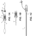
- FIGS. 1A-1C illustrate a conventional delivery apparatus 110 and sheath 9 for delivering a prosthetic implant, such as a prosthetic heart valve, to a patient.
- a prosthetic implant such as a prosthetic heart valve
- the delivery apparatus 110 illustrated herein generally includes a steerable guide catheter 114 and a balloon catheter 116 extending through the guide catheter 114.
- the guide catheter 114 and the balloon catheter 116 illustrated in Figs. 1A-1B are adapted to slide longitudinally relative to each other to facilitate delivery and positioning of prosthetic heart valve at an implantation site in a patient's body.
- the guide catheter 114 includes a handle portion 120 and an elongated guide tube, or shaft, 122 extending from handle portion 120 ( FIG. 1B ).
- FIG. 1C illustrates a conventional expandable sheath 9 that is used to introduce the delivery apparatus 110 and the prosthetic device into the patient's body.
- a conventional expandable sheath 9 has generally tubular configuration defining a central lumen to guide passage of the delivery system for the prosthetic heart valve.
- the expandable sheath 9 includes a hemostasis valve that prevents leakage of pressurized blood.
- a distal end of the sheath 9 is passed into the vessel (such as a femoral artery) of the patient by sliding the lumen of sheath 9 over a previously inserted introducer (which may have the shape of a rigid, tapered rod).
- the introducer is then removed through the lumen of the sheath 9.
- the delivery apparatus 110 (with its implant) can then inserted through the hemostasis valve, into the lumen of sheath 9, and advanced through the patient's vasculature where the implant is delivered and implanted within the patient.
- an introducer also called a dilator
- the introducer provides sufficient rigidity not to buckle or bend during insertion, and the more flaccid conventional sheath 9 can then be inserted over the introducer and into the vessel.
- the introducer is removed once the sheath 9 is inserted into the patient's vessel (prior to insertion of the delivery apparatus 110 through the sheath 9).
- a combined introducer and expandable sheath has a unitary structure that serves as both sheath and introducer, thus eliminating the preliminary steps of dilating the vascular site and removing the introducer before inserting the delivery apparatus.
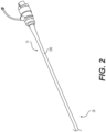
- the combined introducer and expandable sheath 10 (hereinafter, the introducer sheath 10) includes an outer elastomeric jacket 330 extending along the longitudinal axis of the sheath, as shown in FIG. 2 .
- FIGS. 3A and 4 illustrate a cross section of an introducer sheath 10 in which the same structure serves as both the sheath and a dilator.
- FIG. 5 shows an embodiment of the inner member of introducer sheath 10 (without outer jacket elastomeric 330 for illustration purposes).
- FIG. 3A illustrates a cross section the introducer sheath 10 in an unexpanded state.
- the introducer sheath 10 includes an outer elastomeric jacket 330 and an inner member 334 within the elastomeric jacket 330.
- inner member 334 defines an inner lumen 338 having an inner diameter ID.
- the unexpanded inner diameter of the inner member 334 i.e., the diameter of inner lumen 338) may be about 1.0 mm (0.04 inches, a size that is compatible with a guide wire having an outer diameter of about 0.038 inches, i.e. about 0.97 mm).
- the outer diameter OD of the introducer sheath 10, including elastomeric jacket 330 can be from about 3.302 mm (0.13 inches) to about 4.572 mm (0.18 inches).
- the inner diameter ID of the inner member 334 (the expanded ID) can be from about 7.112 mm (0.28 inches) to about 8.382 mm (0.33 inches).
- This high expanded inner diameter ID is granted by the high inner surface area allotted by the many radial folds; in cross section, the full perimeter of the unexpanded inner surface of the inner member 334 (including the surface within the radial folds) is greater than the perimeter of circle having a diameter of 7.62 mm (0.30 inches).
- the outer diameter OD of the introducer sheath 10 can be from about 8.636 mm (0.34 inches) to about 9.398 mm (0.37 inches).
- the inner member 334 comprises a plurality of radially folded tapered segments 342.
- the inner lumen 338 is at least partially defined by a plurality of inner surfaces 343 of the tapered segments 342.
- each tapered segment 342 widens as it extends radially outward (from an inner surface 343 of a tapered segment 342 to an outer surface 345 of a tapered segment 342).
- the thickness t of a tapered segment can range from about 1.143 mm (0.045 inches) to about 1.778 mm (0.07 inches).
- This thickness is relatively high as compared to conventional sheaths, which typically have a wall thickness of about 0.254 mm (0.010 inches) to about 0.508 mm (0.020 inches). This relatively large thickness gives the introducer sheath 10 disclosed herein a greater columnar strength to help eliminate the need for an introducer/dilator during the insertion procedure. Furthermore, the relative thickness of the radial folds is high compared to current expandable sheaths that utilize folds as part of the expansion mechanism. This greater thickness of the radial folds allows for a much higher degree of expansion (greater difference between unexpanded outer diameter and expanded outer diameter), facilitating the design of smaller profile sheaths.
- FIG. 3B An enlarged portion of FIG. 3A is shown in FIG. 3B .
- a selected tapered segment 347 is connected to a first circumferentially adjacent tapered segment 349 at an inner connection point 359, which is positioned adjacent the inner lumen 338 defined by the inner member 334.
- the same selected tapered segment 347 is connected to a second circumferentially adjacent tapered segment 351 at an outer connection point 361, which is positioned adjacent the outer surface 353 of the inner member 334.
- the connection points 359, 361 are thinner in a radial direction than the tapered segments 342 of the inner member 334, such that the inner member 334 thins and widens traveling along its circumference (as shown, for example, in FIG. 4 ).
- the inner member 334 defines a plurality of outwardly extending gaps 355 that extend radially outward from inner lumen 338, as shown in FIG. 3A .
- the outwardly extending gaps 355 travel at least a portion of the length of inner member 334, as shown in FIG. 5 .
- a plurality of inwardly extending gaps 357 extend radially inward from the outer surface of inner member 334, and also travel at least a portion of the length of the inner member 334, as shown in FIGS. 3A and FIG. 5 .
- Each of the outwardly and inwardly extending gaps 355, 357 are at least partially defined by two adjacent tapered segments 342.
- the inner member 334 bends at the inner and outer connection points 359, 361 to cause tapered segments 342 to separate and widen the inwardly and outwardly extending gaps 355, 357, as shown in FIG. 4 .
- FIG. 4 illustrates a cross section of introducer sheath 10 in an expanded state.
- the elastomeric jacket 330 thins and the radially folded tapered segments 342 of the inner member 334 unfold towards the elastomeric jacket 330 to expand/widen the lumen 338.
- the expansion is provided by the insertion of a medical delivery device.
- the device for example, may be a transcatheter heart valve (THV) delivery device provided over a guide wire through the lumen of the inner member 334.
- TSV transcatheter heart valve
- the medical delivery device mechanically pushes open the tapered segments 342 of the inner member 334, as illustrated in FIG. 4 .
- TSV transcatheter heart valve
- the outer elastomeric jacket 330 also expands to an increased outer diameter with the insertion of the medical device in the lumen 338 of the inner member 334. Upon removal of the medical device, the outer jacket material supplies sufficient elasticity to return the folded inner member 334 back to the unexpanded/folded state after THV passage and supply hemostasis for the inner member exterior channels.
- FIG. 5 illustrates an inner member 334 of an introducer sheath 10 according to principles described herein.
- the inner member 334 is substantially cylindrical and can be extruded with a proximal bump/taper 346.
- the proximal bump/taper 346 facilitates the mating of the introducer sheath 10 to the wider hemostasis valve housing during the manufacturing process.
- the ratio of the outer diameter to inner diameter at the bump/taper 346 region is higher than at other regions along the length of the introducer sheath 10. This higher OD/ID translates to more wall material (greater wall thickness t), which gives good force transmission down the length of the introducer sheath 10.
- inner member 334 may also include a tapered and rounded tip 350 to assist in dilation of the vasculature during introduction of the introducer sheath 10.
- the inner member 334 may be fixed with respect to the outer elastomeric jacket or jacket or may "float" relative to the outer sheath.
- the inner member 334 and the outer elastomeric jacket 330 may be attached, by, for example, adhesives or heat bonding, at fixed locations such that they do not move relative to one another or may be connected to one another.
- the inner member 334 and the outer elastomeric jacket 330 may be attached at the tip 350 of the introducer sheath 10, or they may be attached along portions of the length of the introducer sheath 10.
- the inner member 334 and the outer elastomeric jacket 330 may be formed independently or in an integral process. If formed independently, the elastomeric jacket 330 may be expanded by known means, the inner member 334 inserted into the elastomeric jacket 330 and the elastomeric jacket 330 allowed to contract around the inner member 334. The compressive force of the elastomeric jacket 330 around the inner member 334 may be sufficient to reduce movement between the elastomeric jacket 330 and the inner member 334 sufficiently to serve the functions described herein.
- inner member 334 has substantial column strength to provide rigidity to the elastomeric jacket 330 for catheter insertion, high lubricity for guide wire and THV passage, and high pliability so expansion force is low.
- the inner member 334 may be made of a material such as high density polyethylene, fluoropolymers, Teflon or other material.
- the inner member 334 can have a durometer of from about 45 D to about 65 D.
- the introducer sheath 10 provides sufficient rigidity to be able to be inserted through the skin of a patient and into the circulatory system.
- An alternative is to use a co-extruded inner member to get the desired properties in the locations required.
Landscapes
- Health & Medical Sciences (AREA)
- Cardiology (AREA)
- Engineering & Computer Science (AREA)
- Biomedical Technology (AREA)
- Life Sciences & Earth Sciences (AREA)
- Transplantation (AREA)
- Heart & Thoracic Surgery (AREA)
- Vascular Medicine (AREA)
- Oral & Maxillofacial Surgery (AREA)
- Animal Behavior & Ethology (AREA)
- General Health & Medical Sciences (AREA)
- Public Health (AREA)
- Veterinary Medicine (AREA)
- Mechanical Engineering (AREA)
- Media Introduction/Drainage Providing Device (AREA)
- Prostheses (AREA)
- Surgical Instruments (AREA)
Claims (15)
- Kombination aus Inserter und expandierbarer Hülle (10), aufweisend:ein langgestrecktes inneres Glied (334) mit einer Mehrzahl von radial gefalteten verjüngten Segmenten (342), die sich in einem nicht expandierten Zustand in einer Längsrichtung entlang einer Längsachse erstrecken, wobei das innere Glied (334) ein inneres Lumen (338) mit einem Innendurchmesser (10) definiert;einen langgestreckten äußeren Elastomermantel (330), der sich zumindest teilweise über das innere Glied (334) erstreckt und eine Federvorspannung hin zum inneren Lumen (338) des inneren Glieds (334) hat;dadurch gekennzeichnet, dass die Dicke (t) eines verjüngten Segments (342) gemessen in einem nicht expandierten Zustand von einer Innenfläche (343) des verjüngten Segments zu einer Außenfläche (345) des verjüngten Segmentes 1,143 mm bis 1,778 mm ist, so dass das innere Glied (334) der Kombination aus Inserter und expandierbarer Hülle (10) eine ausreichende Steifigkeit zum Einführen in das Gefäßsystem eines Patienten bereitstellt.
- Kombination aus Inserter und expandierbarer Hülle nach Anspruch 1, wobei das innere Glied (334) ein zentrales Lumen definiert, wobei sich das zentrale Lumen in der Längsrichtung erstreckt.
- Kombination aus Inserter und expandierbarer Hülle nach einem der Ansprüche 1 oder 2, wobei sich die Mehrzahl von radial gefalteten verjüngten Segmenten (342) in Richtung einer inneren Oberfläche des äußeren Elastomermantels (330) entfalten, um den inneren Durchmesser des inneren Lumens (338) beim Einführen einer medizinischen Zuführvorrichtung in das Lumen (338) zu expandieren.
- Kombination aus Inserter und expandierbarer Hülle nach einem der Ansprüche 1 bis 3, ferner aufweisend einen Zugentlastungsabschnitt, der sich distal von dem Ende des äußeren Elastomermantels (330) erstreckt, wobei der äußere Elastomermantel (330) an dem Zugentlastungsabschnitt befestigt ist.
- Kombination aus Inserter und expandierbarer Hülle nach Anspruch 1, wobei das innere Glied (334) ferner eine verjüngte und abgerundete distale Spitze (350) aufweist.
- Kombination aus Inserter und expandierbarer Hülle nach einem der Ansprüche 1 bis 4, wobei das innere Glied (334) mit Bezug zum äußeren Elastomermantel (330) eine in Längsrichtung fixierte Position hat.
- Kombination aus Inserter und expandierbarer Hülle nach einem der Ansprüche 1 bis 6, wobei in einem nicht expandierten Zustand das innere Lumen (338) zumindest teilweise durch Innenflächen (343) der radial gefalteten verjüngten Segmente (342) definiert ist, und wobei vorzugsweise der Durchmesser des inneren Lumens (338) 1 mm beträgt.
- Kombination aus Inserter und expandierbarer Hülle nach einem der Ansprüche 1 bis 7, wobei das innere Glied (334) eine Härte von 45 D bis 65 D aufweist.
- Kombination aus Inserter und expandierbarer Hülle nach einem der Ansprüche 1 bis 8, wobei sich jedes der radial gefalteten verjüngten Segmente (342) beim radialen Erstrecken nach außen aufweitet.
- Kombination aus Inserter und expandierbarer Hülle nach Anspruch 9, wobei ein ausgewähltes verjüngtes Segment (347) an einem inneren Verbindungspunkt (359) mit einem ersten in Umfangsrichtung benachbarten verjüngten Segment (349) und an einem äußeren Verbindungspunkt (361) mit einem zweiten in Umfangsrichtung benachbarten verjüngten Segment (351) verbunden ist.
- Kombination aus Inserter und expandierbarer Hülle nach Anspruch 10, wobei in einem nicht expandierten Zustand der innere Verbindungspunkt (359) benachbart zum inneren Lumen (338) des inneren Glieds (334) und der äußere Verbindungspunkt (361) benachbart zu einer Außenfläche (353) des inneren Glieds (334) positioniert ist.
- Kombination aus Inserter und expandierbarer Hülle nach einem der Ansprüche 10 oder 11, wobei die inneren und äußeren Verbindungspunkte (359, 361) in einer radialen Richtung dünner sind als die verjüngten Segmente (342) des inneren Glieds (334).
- Kombination aus Inserter und expandierbarer Hülle nach einem der Ansprüche 11 oder 12, wobei sich das innere Glied (334) entlang seines Umfangs verdünnt und verbreitert.
- Kombination aus Inserter und expandierbarer Hülle nach einem der Ansprüche 9 bis 13, ferner aufweisend eine Mehrzahl von sich nach außen erstreckenden Lücken (355), die sich von dem inneren Lumen (338) und zwischen benachbarten konischen Segmenten (342) radial nach außen erstrecken, und eine Mehrzahl von sich nach innen erstreckenden Lücken (357), die sich von einer Außenfläche des inneren Glieds (334) radial nach innen erstrecken.
- Kombination aus Inserter und expandierbarer Hülle nach Anspruch 14, wobei die sich nach innen und nach außen erstreckenden Lücken (355, 357) sich jeweils über zumindest einen Teil der Länge des inneren Glieds (334) erstrecken.
Priority Applications (1)
| Application Number | Priority Date | Filing Date | Title |
|---|---|---|---|
| EP24157224.7A EP4378425A3 (de) | 2018-12-12 | 2019-12-06 | Kombination aus einführvorrichtung und expandierbarer hülle |
Applications Claiming Priority (2)
| Application Number | Priority Date | Filing Date | Title |
|---|---|---|---|
| US201862778698P | 2018-12-12 | 2018-12-12 | |
| PCT/US2019/064875 WO2020123281A1 (en) | 2018-12-12 | 2019-12-06 | Combined introducer and expandable sheath |
Related Child Applications (1)
| Application Number | Title | Priority Date | Filing Date |
|---|---|---|---|
| EP24157224.7A Division EP4378425A3 (de) | 2018-12-12 | 2019-12-06 | Kombination aus einführvorrichtung und expandierbarer hülle |
Publications (2)
| Publication Number | Publication Date |
|---|---|
| EP3893818A1 EP3893818A1 (de) | 2021-10-20 |
| EP3893818B1 true EP3893818B1 (de) | 2024-02-14 |
Family
ID=69570812
Family Applications (2)
| Application Number | Title | Priority Date | Filing Date |
|---|---|---|---|
| EP19850742.8A Active EP3893818B1 (de) | 2018-12-12 | 2019-12-06 | Kombinierte einführvorrichtung und dehnbare hülle |
| EP24157224.7A Pending EP4378425A3 (de) | 2018-12-12 | 2019-12-06 | Kombination aus einführvorrichtung und expandierbarer hülle |
Family Applications After (1)
| Application Number | Title | Priority Date | Filing Date |
|---|---|---|---|
| EP24157224.7A Pending EP4378425A3 (de) | 2018-12-12 | 2019-12-06 | Kombination aus einführvorrichtung und expandierbarer hülle |
Country Status (6)
| Country | Link |
|---|---|
| US (2) | US12263086B2 (de) |
| EP (2) | EP3893818B1 (de) |
| JP (2) | JP2022513213A (de) |
| CN (2) | CN119606605A (de) |
| ES (1) | ES2984176T3 (de) |
| WO (1) | WO2020123281A1 (de) |
Families Citing this family (2)
| Publication number | Priority date | Publication date | Assignee | Title |
|---|---|---|---|---|
| CN112807521A (zh) * | 2020-11-24 | 2021-05-18 | 邓三明 | 一种单向活瓣开放装置及包括其的留置针及支气管支架 |
| CN115737010B (zh) * | 2022-12-09 | 2024-04-19 | 上海珩畅医疗科技有限公司 | 一种用于介入治疗设备的扩张器 |
Family Cites Families (151)
| Publication number | Priority date | Publication date | Assignee | Title |
|---|---|---|---|---|
| US519297A (en) | 1894-05-01 | Bauer | ||
| US4035849A (en) | 1975-11-17 | 1977-07-19 | William W. Angell | Heart valve stent and process for preparing a stented heart valve prosthesis |
| US4592340A (en) | 1984-05-02 | 1986-06-03 | Boyles Paul W | Artificial catheter means |
| JPS63158064A (ja) | 1986-12-23 | 1988-07-01 | テルモ株式会社 | 血管拡張カテ−テル |
| US5266073A (en) | 1987-12-08 | 1993-11-30 | Wall W Henry | Angioplasty stent |
| US4994077A (en) | 1989-04-21 | 1991-02-19 | Dobben Richard L | Artificial heart valve for implantation in a blood vessel |
| US5318529A (en) | 1989-09-06 | 1994-06-07 | Boston Scientific Corporation | Angioplasty balloon catheter and adaptor |
| US5059177A (en) | 1990-04-19 | 1991-10-22 | Cordis Corporation | Triple lumen balloon catheter |
| US5411552A (en) | 1990-05-18 | 1995-05-02 | Andersen; Henning R. | Valve prothesis for implantation in the body and a catheter for implanting such valve prothesis |
| DK124690D0 (da) | 1990-05-18 | 1990-05-18 | Henning Rud Andersen | Klapprotes til implantering i kroppen for erstatning af naturlig klap samt kateter til brug ved implantering af en saadan klapprotese |
| US5176698A (en) | 1991-01-09 | 1993-01-05 | Scimed Life Systems, Inc. | Vented dilatation cathether and method for venting |
| US5370685A (en) | 1991-07-16 | 1994-12-06 | Stanford Surgical Technologies, Inc. | Endovascular aortic valve replacement |
| IL103445A (en) | 1991-10-18 | 1997-04-15 | Ethicon Inc | Endoscopic tissue manipulator |
| US5192297A (en) | 1991-12-31 | 1993-03-09 | Medtronic, Inc. | Apparatus and method for placement and implantation of a stent |
| US5325845A (en) | 1992-06-08 | 1994-07-05 | Adair Edwin Lloyd | Steerable sheath for use with selected removable optical catheter |
| US5824044A (en) | 1994-05-12 | 1998-10-20 | Endovascular Technologies, Inc. | Bifurcated multicapsule intraluminal grafting system |
| US5728068A (en) | 1994-06-14 | 1998-03-17 | Cordis Corporation | Multi-purpose balloon catheter |
| JP3970341B2 (ja) | 1994-06-20 | 2007-09-05 | テルモ株式会社 | 血管カテーテル |
| US5554185A (en) | 1994-07-18 | 1996-09-10 | Block; Peter C. | Inflatable prosthetic cardiovascular valve for percutaneous transluminal implantation of same |
| US5632760A (en) | 1994-10-20 | 1997-05-27 | Cordis Corporation | Balloon catheter for stent implantation |
| US5599305A (en) | 1994-10-24 | 1997-02-04 | Cardiovascular Concepts, Inc. | Large-diameter introducer sheath having hemostasis valve and removable steering mechanism |
| US5779688A (en) | 1994-10-28 | 1998-07-14 | Intella Interventional Systems, Inc. | Low profile balloon-on-a-wire catheter with shapeable and/or deflectable tip and method |
| US5639274A (en) | 1995-06-02 | 1997-06-17 | Fischell; Robert E. | Integrated catheter system for balloon angioplasty and stent delivery |
| DE19532846A1 (de) | 1995-09-06 | 1997-03-13 | Georg Dr Berg | Ventileinrichtung |
| US5591195A (en) | 1995-10-30 | 1997-01-07 | Taheri; Syde | Apparatus and method for engrafting a blood vessel |
| US6579305B1 (en) | 1995-12-07 | 2003-06-17 | Medtronic Ave, Inc. | Method and apparatus for delivery deployment and retrieval of a stent comprising shape-memory material |
| US20050245894A1 (en) | 1996-05-20 | 2005-11-03 | Medtronic Vascular, Inc. | Methods and apparatuses for drug delivery to an intravascular occlusion |
| US6217585B1 (en) | 1996-08-16 | 2001-04-17 | Converge Medical, Inc. | Mechanical stent and graft delivery system |
| JP3968444B2 (ja) | 1996-08-23 | 2007-08-29 | ボストン サイエンティフィック サイムド,インコーポレイテッド | ステント固定装置を具備するステント搬送機構 |
| US5968068A (en) | 1996-09-12 | 1999-10-19 | Baxter International Inc. | Endovascular delivery system |
| US5749890A (en) | 1996-12-03 | 1998-05-12 | Shaknovich; Alexander | Method and system for stent placement in ostial lesions |
| EP0850607A1 (de) | 1996-12-31 | 1998-07-01 | Cordis Corporation | Klappenprothese zur Implantation in Körperkanälen |
| US5944690A (en) | 1997-03-17 | 1999-08-31 | C.R. Bard, Inc. | Slidable control mechanism for steerable catheter |
| US6019777A (en) | 1997-04-21 | 2000-02-01 | Advanced Cardiovascular Systems, Inc. | Catheter and method for a stent delivery system |
| US6143016A (en) | 1997-04-21 | 2000-11-07 | Advanced Cardiovascular Systems, Inc. | Sheath and method of use for a stent delivery system |
| US6162208A (en) | 1997-09-11 | 2000-12-19 | Genzyme Corporation | Articulating endoscopic implant rotator surgical apparatus and method for using same |
| US5916147A (en) | 1997-09-22 | 1999-06-29 | Boury; Harb N. | Selectively manipulable catheter |
| US5961536A (en) | 1997-10-14 | 1999-10-05 | Scimed Life Systems, Inc. | Catheter having a variable length balloon and method of using the same |
| US6027510A (en) | 1997-12-08 | 2000-02-22 | Inflow Dynamics Inc. | Stent delivery system |
| US6530952B2 (en) | 1997-12-29 | 2003-03-11 | The Cleveland Clinic Foundation | Bioprosthetic cardiovascular valve system |
| US6251092B1 (en) | 1997-12-30 | 2001-06-26 | Medtronic, Inc. | Deflectable guiding catheter |
| US6174327B1 (en) | 1998-02-27 | 2001-01-16 | Scimed Life Systems, Inc. | Stent deployment apparatus and method |
| US6527979B2 (en) | 1999-08-27 | 2003-03-04 | Corazon Technologies, Inc. | Catheter systems and methods for their use in the treatment of calcified vascular occlusions |
| US6500147B2 (en) | 1999-02-22 | 2002-12-31 | Medtronic Percusurge, Inc. | Flexible catheter |
| DE19907646A1 (de) | 1999-02-23 | 2000-08-24 | Georg Berg | Ventileinrichtung zum Einsetzen in ein Hohlorgan |
| US6514228B1 (en) | 1999-03-05 | 2003-02-04 | Scimed Life Systems, Inc. | Balloon catheter having high flow tip |
| US7226467B2 (en) | 1999-04-09 | 2007-06-05 | Evalve, Inc. | Fixation device delivery catheter, systems and methods of use |
| US6858034B1 (en) | 1999-05-20 | 2005-02-22 | Scimed Life Systems, Inc. | Stent delivery system for prevention of kinking, and method of loading and using same |
| US6544279B1 (en) | 2000-08-09 | 2003-04-08 | Incept, Llc | Vascular device for emboli, thrombus and foreign body removal and methods of use |
| US6383171B1 (en) | 1999-10-12 | 2002-05-07 | Allan Will | Methods and devices for protecting a passageway in a body when advancing devices through the passageway |
| US6471672B1 (en) | 1999-11-10 | 2002-10-29 | Scimed Life Systems | Selective high pressure dilation balloon |
| US7018406B2 (en) | 1999-11-17 | 2006-03-28 | Corevalve Sa | Prosthetic valve for transluminal delivery |
| FR2800984B1 (fr) | 1999-11-17 | 2001-12-14 | Jacques Seguin | Dispositif de remplacement d'une valve cardiaque par voie percutanee |
| FR2815844B1 (fr) | 2000-10-31 | 2003-01-17 | Jacques Seguin | Support tubulaire de mise en place, par voie percutanee, d'une valve cardiaque de remplacement |
| US6458153B1 (en) | 1999-12-31 | 2002-10-01 | Abps Venture One, Ltd. | Endoluminal cardiac and venous valve prostheses and methods of manufacture and delivery thereof |
| PL201632B1 (pl) | 2000-01-31 | 2009-04-30 | Cook Biotech | Zespół zastawki stentu |
| US6454799B1 (en) | 2000-04-06 | 2002-09-24 | Edwards Lifesciences Corporation | Minimally-invasive heart valves and methods of use |
| WO2002022054A1 (en) | 2000-09-12 | 2002-03-21 | Gabbay S | Valvular prosthesis and method of using same |
| US7510572B2 (en) | 2000-09-12 | 2009-03-31 | Shlomo Gabbay | Implantation system for delivery of a heart valve prosthesis |
| US6461382B1 (en) | 2000-09-22 | 2002-10-08 | Edwards Lifesciences Corporation | Flexible heart valve having moveable commissures |
| DE60115280T2 (de) | 2000-12-15 | 2006-08-10 | Angiomed Gmbh & Co. Medizintechnik Kg | Stent mit herzklappe |
| US6764504B2 (en) | 2001-01-04 | 2004-07-20 | Scimed Life Systems, Inc. | Combined shaped balloon and stent protector |
| JP4195612B2 (ja) | 2001-01-30 | 2008-12-10 | エドワーズ ライフサイエンシーズ アーゲー | 管外組織構造を改善する医療システム及び方法 |
| US7011094B2 (en) | 2001-03-02 | 2006-03-14 | Emphasys Medical, Inc. | Bronchial flow control devices and methods of use |
| US6733525B2 (en) | 2001-03-23 | 2004-05-11 | Edwards Lifesciences Corporation | Rolled minimally-invasive heart valves and methods of use |
| US7374571B2 (en) | 2001-03-23 | 2008-05-20 | Edwards Lifesciences Corporation | Rolled minimally-invasive heart valves and methods of manufacture |
| US7556646B2 (en) | 2001-09-13 | 2009-07-07 | Edwards Lifesciences Corporation | Methods and apparatuses for deploying minimally-invasive heart valves |
| US6585718B2 (en) | 2001-05-02 | 2003-07-01 | Cardiac Pacemakers, Inc. | Steerable catheter with shaft support system for resisting axial compressive loads |
| US6776765B2 (en) | 2001-08-21 | 2004-08-17 | Synovis Life Technologies, Inc. | Steerable stylet |
| US6893460B2 (en) | 2001-10-11 | 2005-05-17 | Percutaneous Valve Technologies Inc. | Implantable prosthetic valve |
| US6962597B2 (en) | 2001-10-24 | 2005-11-08 | Scimed Life Systems, Inc. | Inner member support block |
| US7594926B2 (en) | 2001-11-09 | 2009-09-29 | Boston Scientific Scimed, Inc. | Methods, systems and devices for delivering stents |
| US20070073389A1 (en) | 2001-11-28 | 2007-03-29 | Aptus Endosystems, Inc. | Endovascular aneurysm devices, systems, and methods |
| US7137993B2 (en) | 2001-12-03 | 2006-11-21 | Xtent, Inc. | Apparatus and methods for delivery of multiple distributed stents |
| US20030120341A1 (en) | 2001-12-21 | 2003-06-26 | Hani Shennib | Devices and methods of repairing cardiac valves |
| DE10362367B3 (de) | 2002-08-13 | 2022-02-24 | Jenavalve Technology Inc. | Vorrichtung zur Verankerung und Ausrichtung von Herzklappenprothesen |
| US7137184B2 (en) | 2002-09-20 | 2006-11-21 | Edwards Lifesciences Corporation | Continuous heart valve support frame and method of manufacture |
| WO2004037333A1 (en) | 2002-10-25 | 2004-05-06 | Nmt Medical, Inc. | Expandable sheath tubing |
| US7399315B2 (en) | 2003-03-18 | 2008-07-15 | Edwards Lifescience Corporation | Minimally-invasive heart valve with cusp positioners |
| EP1615595B1 (de) | 2003-04-24 | 2009-10-21 | Cook Incorporated | Künstliche klappe für blutgefäss mit verbessertem fliessverhalten |
| US8007489B2 (en) * | 2003-06-25 | 2011-08-30 | Volcano Corporation | Method and apparatus for curving a catheter |
| US8500792B2 (en) | 2003-09-03 | 2013-08-06 | Bolton Medical, Inc. | Dual capture device for stent graft delivery system and method for capturing a stent graft |
| US7758625B2 (en) | 2003-09-12 | 2010-07-20 | Abbott Vascular Solutions Inc. | Delivery system for medical devices |
| US7553324B2 (en) | 2003-10-14 | 2009-06-30 | Xtent, Inc. | Fixed stent delivery devices and methods |
| US8603160B2 (en) | 2003-12-23 | 2013-12-10 | Sadra Medical, Inc. | Method of using a retrievable heart valve anchor with a sheath |
| US7887574B2 (en) | 2003-12-23 | 2011-02-15 | Scimed Life Systems, Inc. | Stent delivery catheter |
| US8128692B2 (en) | 2004-02-27 | 2012-03-06 | Aortx, Inc. | Prosthetic heart valves, scaffolding structures, and systems and methods for implantation of same |
| EP1753374A4 (de) | 2004-04-23 | 2010-02-10 | 3F Therapeutics Inc | Implantierbares protheseventil |
| CA2828619C (en) | 2004-05-05 | 2018-09-25 | Direct Flow Medical, Inc. | Prosthetic valve with an elastic stent and a sealing structure |
| JP2008513060A (ja) | 2004-09-14 | 2008-05-01 | エドワーズ ライフサイエンシーズ アーゲー | 心臓弁逆流の処置のためのデバイスおよび方法 |
| US7578838B2 (en) | 2005-01-12 | 2009-08-25 | Cook Incorporated | Delivery system with helical shaft |
| SE531468C2 (sv) | 2005-04-21 | 2009-04-14 | Edwards Lifesciences Ag | En anordning för styrning av blodflöde |
| JP4912395B2 (ja) | 2005-05-24 | 2012-04-11 | エドワーズ ライフサイエンシーズ コーポレイション | 迅速配置式補綴用心臓弁 |
| US20060282149A1 (en) | 2005-06-08 | 2006-12-14 | Xtent, Inc., A Delaware Corporation | Apparatus and methods for deployment of multiple custom-length prostheses (II) |
| US7938851B2 (en) | 2005-06-08 | 2011-05-10 | Xtent, Inc. | Devices and methods for operating and controlling interventional apparatus |
| US7780723B2 (en) | 2005-06-13 | 2010-08-24 | Edwards Lifesciences Corporation | Heart valve delivery system |
| US8167932B2 (en) | 2005-10-18 | 2012-05-01 | Edwards Lifesciences Corporation | Heart valve delivery system with valve catheter |
| US7785366B2 (en) | 2005-10-26 | 2010-08-31 | Maurer Christopher W | Mitral spacer |
| US8778017B2 (en) | 2005-10-26 | 2014-07-15 | Cardiosolutions, Inc. | Safety for mitral valve implant |
| US8449606B2 (en) | 2005-10-26 | 2013-05-28 | Cardiosolutions, Inc. | Balloon mitral spacer |
| US8764820B2 (en) | 2005-11-16 | 2014-07-01 | Edwards Lifesciences Corporation | Transapical heart valve delivery system and method |
| EP1959864B1 (de) | 2005-12-07 | 2018-03-07 | Medtronic, Inc. | Verbindungssysteme für zweistückige prothetische herzklappenanordnungen |
| US8147541B2 (en) | 2006-02-27 | 2012-04-03 | Aortx, Inc. | Methods and devices for delivery of prosthetic heart valves and other prosthetics |
| AU2007227000A1 (en) | 2006-03-20 | 2007-09-27 | Xtent, Inc. | Apparatus and methods for deployment of linked prosthetic segments |
| US20070239254A1 (en) | 2006-04-07 | 2007-10-11 | Chris Chia | System for percutaneous delivery and removal of a prosthetic valve |
| US20070244546A1 (en) | 2006-04-18 | 2007-10-18 | Medtronic Vascular, Inc. | Stent Foundation for Placement of a Stented Valve |
| JP4682259B2 (ja) | 2006-09-08 | 2011-05-11 | エドワーズ ライフサイエンシーズ コーポレイション | 一体型心臓弁送達システム |
| US8029556B2 (en) | 2006-10-04 | 2011-10-04 | Edwards Lifesciences Corporation | Method and apparatus for reshaping a ventricle |
| US7931616B2 (en) | 2006-10-31 | 2011-04-26 | Biosense Webster, Inc. | Insert molded catheter puller member connectors and method of making |
| WO2008126737A1 (ja) | 2007-04-05 | 2008-10-23 | Kaneka Corporation | ステントデリバリーシステム |
| EP2143404B1 (de) | 2007-04-27 | 2012-02-15 | Terumo Kabushiki Kaisha | System zum anbringen eines stents |
| US20080294230A1 (en) | 2007-05-24 | 2008-11-27 | Cook Incorporated | Apparatus and methods for deploying self-expanding stents |
| US20100036473A1 (en) | 2007-06-22 | 2010-02-11 | Icon Medical Corp. | Heatable delivery device |
| US8326878B2 (en) | 2007-07-19 | 2012-12-04 | Carnegie Research, Inc. | System for and method of processing business personnel information |
| CA2978267A1 (en) | 2007-08-23 | 2009-02-23 | Dfm, Llc | Translumenally implantable heart valve with formed in place support |
| US8114154B2 (en) | 2007-09-07 | 2012-02-14 | Sorin Biomedica Cardio S.R.L. | Fluid-filled delivery system for in situ deployment of cardiac valve prostheses |
| US20090138079A1 (en) | 2007-10-10 | 2009-05-28 | Vector Technologies Ltd. | Prosthetic heart valve for transfemoral delivery |
| PL2628464T5 (pl) | 2007-12-14 | 2024-10-28 | Edwards Lifesciences Corporation | Zastawka protetyczna |
| US8157853B2 (en) | 2008-01-24 | 2012-04-17 | Medtronic, Inc. | Delivery systems and methods of implantation for prosthetic heart valves |
| CA3063001A1 (en) | 2008-02-29 | 2009-09-03 | Edwards Lifesciences Corporation | Expandable member for deploying a prosthetic device |
| US20090276040A1 (en) | 2008-05-01 | 2009-11-05 | Edwards Lifesciences Corporation | Device and method for replacing mitral valve |
| US9061119B2 (en) | 2008-05-09 | 2015-06-23 | Edwards Lifesciences Corporation | Low profile delivery system for transcatheter heart valve |
| US8323335B2 (en) | 2008-06-20 | 2012-12-04 | Edwards Lifesciences Corporation | Retaining mechanisms for prosthetic valves and methods for using |
| US7976574B2 (en) | 2008-08-08 | 2011-07-12 | Advanced Cardiovascular Systems, Inc. | Delivery system with variable delivery rate for deploying a medical device |
| US8652202B2 (en) | 2008-08-22 | 2014-02-18 | Edwards Lifesciences Corporation | Prosthetic heart valve and delivery apparatus |
| JP5577343B2 (ja) | 2008-09-22 | 2014-08-20 | ボストン サイエンティフィック サイムド,インコーポレイテッド | バルーン付きカテーテル |
| EP2341871B1 (de) | 2008-10-01 | 2017-03-22 | Edwards Lifesciences CardiAQ LLC | Abgabesystem für ein gefässimplantat |
| US9149376B2 (en) | 2008-10-06 | 2015-10-06 | Cordis Corporation | Reconstrainable stent delivery system |
| US8790387B2 (en) * | 2008-10-10 | 2014-07-29 | Edwards Lifesciences Corporation | Expandable sheath for introducing an endovascular delivery device into a body |
| US8308798B2 (en) | 2008-12-19 | 2012-11-13 | Edwards Lifesciences Corporation | Quick-connect prosthetic heart valve and methods |
| US20100174363A1 (en) | 2009-01-07 | 2010-07-08 | Endovalve, Inc. | One Piece Prosthetic Valve Support Structure and Related Assemblies |
| EP4119098A1 (de) | 2009-04-15 | 2023-01-18 | Edwards Lifesciences CardiAQ LLC | Gefässimplantat und freisetzungssystem |
| US8475522B2 (en) | 2009-07-14 | 2013-07-02 | Edwards Lifesciences Corporation | Transapical delivery system for heart valves |
| US20110137331A1 (en) | 2009-12-07 | 2011-06-09 | Michael Walsh | Perfusion device |
| US8475523B2 (en) | 2010-02-17 | 2013-07-02 | Medtronic, Inc. | Distal tip assembly for a heart valve delivery catheter |
| CA3020195C (en) | 2010-10-05 | 2020-10-27 | Edwards Lifesciences Corporation | Prosthetic heart valve |
| US9155619B2 (en) | 2011-02-25 | 2015-10-13 | Edwards Lifesciences Corporation | Prosthetic heart valve delivery apparatus |
| US9339384B2 (en) | 2011-07-27 | 2016-05-17 | Edwards Lifesciences Corporation | Delivery systems for prosthetic heart valve |
| US9827093B2 (en) | 2011-10-21 | 2017-11-28 | Edwards Lifesciences Cardiaq Llc | Actively controllable stent, stent graft, heart valve and method of controlling same |
| WO2014186414A1 (en) * | 2013-05-17 | 2014-11-20 | Transaortic Medical, Inc. | Expandable introducer sheath |
| US10918829B2 (en) * | 2015-01-22 | 2021-02-16 | Boston Scientific Scimed, Inc. | Fully compliant large bore expandable sheath |
| US12194256B2 (en) * | 2015-04-10 | 2025-01-14 | Edwards Lifesciences Corporation | Expandable sheath |
| US10792471B2 (en) | 2015-04-10 | 2020-10-06 | Edwards Lifesciences Corporation | Expandable sheath |
| US10398469B2 (en) | 2015-07-17 | 2019-09-03 | Creganna Unlimited Company | Expandable introducer sheath |
| US10588744B2 (en) | 2015-09-04 | 2020-03-17 | Edwards Lifesciences Corporation | Delivery system for prosthetic heart valve |
| US10603165B2 (en) | 2016-12-06 | 2020-03-31 | Edwards Lifesciences Corporation | Mechanically expanding heart valve and delivery apparatus therefor |
| US10912919B2 (en) * | 2017-01-23 | 2021-02-09 | Edwards Lifesciences Corporation | Expandable sheath |
| US10799685B2 (en) * | 2017-03-09 | 2020-10-13 | Edwards Lifesciences Corporation | Expandable sheath with longitudinally extending reinforcing members |
| EP3618768B1 (de) * | 2017-05-05 | 2024-08-28 | St. Jude Medical, Cardiology Division, Inc. | Einführschleuse mit expandierbaren teilen |
| US10869759B2 (en) | 2017-06-05 | 2020-12-22 | Edwards Lifesciences Corporation | Mechanically expandable heart valve |
| US11779728B2 (en) * | 2018-11-01 | 2023-10-10 | Edwards Lifesciences Corporation | Introducer sheath with expandable introducer |
-
2019
- 2019-12-06 WO PCT/US2019/064875 patent/WO2020123281A1/en not_active Ceased
- 2019-12-06 ES ES19850742T patent/ES2984176T3/es active Active
- 2019-12-06 CN CN202411816821.2A patent/CN119606605A/zh active Pending
- 2019-12-06 JP JP2021533620A patent/JP2022513213A/ja active Pending
- 2019-12-06 EP EP19850742.8A patent/EP3893818B1/de active Active
- 2019-12-06 CN CN201980081845.9A patent/CN113226224B/zh active Active
- 2019-12-06 EP EP24157224.7A patent/EP4378425A3/de active Pending
-
2021
- 2021-06-09 US US17/342,866 patent/US12263086B2/en active Active
-
2024
- 2024-11-18 JP JP2024201126A patent/JP2025028064A/ja active Pending
- 2024-11-26 US US18/960,004 patent/US20250082469A1/en active Pending
Also Published As
| Publication number | Publication date |
|---|---|
| US20210290376A1 (en) | 2021-09-23 |
| US12263086B2 (en) | 2025-04-01 |
| CN113226224A (zh) | 2021-08-06 |
| CN119606605A (zh) | 2025-03-14 |
| WO2020123281A1 (en) | 2020-06-18 |
| EP4378425A2 (de) | 2024-06-05 |
| CN113226224B (zh) | 2024-12-27 |
| JP2022513213A (ja) | 2022-02-07 |
| ES2984176T3 (es) | 2024-10-29 |
| EP4378425A3 (de) | 2024-09-25 |
| JP2025028064A (ja) | 2025-02-28 |
| US20250082469A1 (en) | 2025-03-13 |
| EP3893818A1 (de) | 2021-10-20 |
Similar Documents
| Publication | Publication Date | Title |
|---|---|---|
| US11633280B2 (en) | Active introducer sheath system | |
| US12090282B2 (en) | Expandable sheath | |
| US11707605B2 (en) | Expandable sheath with longitudinally extending reinforcing members | |
| CN113017925B (zh) | 可膨胀的护套 | |
| US20250082469A1 (en) | Combined introducer and expandable sheath | |
| EP3826821B1 (de) | Verfahren zur herstellung einer dehnbaren hülle |
Legal Events
| Date | Code | Title | Description |
|---|---|---|---|
| STAA | Information on the status of an ep patent application or granted ep patent |
Free format text: STATUS: UNKNOWN |
|
| STAA | Information on the status of an ep patent application or granted ep patent |
Free format text: STATUS: THE INTERNATIONAL PUBLICATION HAS BEEN MADE |
|
| PUAI | Public reference made under article 153(3) epc to a published international application that has entered the european phase |
Free format text: ORIGINAL CODE: 0009012 |
|
| STAA | Information on the status of an ep patent application or granted ep patent |
Free format text: STATUS: REQUEST FOR EXAMINATION WAS MADE |
|
| 17P | Request for examination filed |
Effective date: 20210712 |
|
| AK | Designated contracting states |
Kind code of ref document: A1 Designated state(s): AL AT BE BG CH CY CZ DE DK EE ES FI FR GB GR HR HU IE IS IT LI LT LU LV MC MK MT NL NO PL PT RO RS SE SI SK SM TR |
|
| DAV | Request for validation of the european patent (deleted) | ||
| DAX | Request for extension of the european patent (deleted) | ||
| GRAP | Despatch of communication of intention to grant a patent |
Free format text: ORIGINAL CODE: EPIDOSNIGR1 |
|
| STAA | Information on the status of an ep patent application or granted ep patent |
Free format text: STATUS: GRANT OF PATENT IS INTENDED |
|
| INTG | Intention to grant announced |
Effective date: 20230829 |
|
| P01 | Opt-out of the competence of the unified patent court (upc) registered |
Effective date: 20230818 |
|
| GRAS | Grant fee paid |
Free format text: ORIGINAL CODE: EPIDOSNIGR3 |
|
| GRAA | (expected) grant |
Free format text: ORIGINAL CODE: 0009210 |
|
| STAA | Information on the status of an ep patent application or granted ep patent |
Free format text: STATUS: THE PATENT HAS BEEN GRANTED |
|
| AK | Designated contracting states |
Kind code of ref document: B1 Designated state(s): AL AT BE BG CH CY CZ DE DK EE ES FI FR GB GR HR HU IE IS IT LI LT LU LV MC MK MT NL NO PL PT RO RS SE SI SK SM TR |
|
| REG | Reference to a national code |
Ref country code: GB Ref legal event code: FG4D |
|
| REG | Reference to a national code |
Ref country code: CH Ref legal event code: EP |
|
| REG | Reference to a national code |
Ref country code: DE Ref legal event code: R096 Ref document number: 602019046658 Country of ref document: DE |
|
| REG | Reference to a national code |
Ref country code: IE Ref legal event code: FG4D |
|
| REG | Reference to a national code |
Ref country code: LT Ref legal event code: MG9D |
|
| REG | Reference to a national code |
Ref country code: NL Ref legal event code: MP Effective date: 20240214 |
|
| PG25 | Lapsed in a contracting state [announced via postgrant information from national office to epo] |
Ref country code: IS Free format text: LAPSE BECAUSE OF FAILURE TO SUBMIT A TRANSLATION OF THE DESCRIPTION OR TO PAY THE FEE WITHIN THE PRESCRIBED TIME-LIMIT Effective date: 20240614 |
|
| PG25 | Lapsed in a contracting state [announced via postgrant information from national office to epo] |
Ref country code: LT Free format text: LAPSE BECAUSE OF FAILURE TO SUBMIT A TRANSLATION OF THE DESCRIPTION OR TO PAY THE FEE WITHIN THE PRESCRIBED TIME-LIMIT Effective date: 20240214 |
|
| PG25 | Lapsed in a contracting state [announced via postgrant information from national office to epo] |
Ref country code: GR Free format text: LAPSE BECAUSE OF FAILURE TO SUBMIT A TRANSLATION OF THE DESCRIPTION OR TO PAY THE FEE WITHIN THE PRESCRIBED TIME-LIMIT Effective date: 20240515 |
|
| REG | Reference to a national code |
Ref country code: AT Ref legal event code: MK05 Ref document number: 1656422 Country of ref document: AT Kind code of ref document: T Effective date: 20240214 |
|
| PG25 | Lapsed in a contracting state [announced via postgrant information from national office to epo] |
Ref country code: HR Free format text: LAPSE BECAUSE OF FAILURE TO SUBMIT A TRANSLATION OF THE DESCRIPTION OR TO PAY THE FEE WITHIN THE PRESCRIBED TIME-LIMIT Effective date: 20240214 Ref country code: RS Free format text: LAPSE BECAUSE OF FAILURE TO SUBMIT A TRANSLATION OF THE DESCRIPTION OR TO PAY THE FEE WITHIN THE PRESCRIBED TIME-LIMIT Effective date: 20240514 Ref country code: NL Free format text: LAPSE BECAUSE OF FAILURE TO SUBMIT A TRANSLATION OF THE DESCRIPTION OR TO PAY THE FEE WITHIN THE PRESCRIBED TIME-LIMIT Effective date: 20240214 |
|
| PG25 | Lapsed in a contracting state [announced via postgrant information from national office to epo] |
Ref country code: AT Free format text: LAPSE BECAUSE OF FAILURE TO SUBMIT A TRANSLATION OF THE DESCRIPTION OR TO PAY THE FEE WITHIN THE PRESCRIBED TIME-LIMIT Effective date: 20240214 |
|
| PG25 | Lapsed in a contracting state [announced via postgrant information from national office to epo] |
Ref country code: RS Free format text: LAPSE BECAUSE OF FAILURE TO SUBMIT A TRANSLATION OF THE DESCRIPTION OR TO PAY THE FEE WITHIN THE PRESCRIBED TIME-LIMIT Effective date: 20240514 Ref country code: NO Free format text: LAPSE BECAUSE OF FAILURE TO SUBMIT A TRANSLATION OF THE DESCRIPTION OR TO PAY THE FEE WITHIN THE PRESCRIBED TIME-LIMIT Effective date: 20240514 Ref country code: NL Free format text: LAPSE BECAUSE OF FAILURE TO SUBMIT A TRANSLATION OF THE DESCRIPTION OR TO PAY THE FEE WITHIN THE PRESCRIBED TIME-LIMIT Effective date: 20240214 Ref country code: LT Free format text: LAPSE BECAUSE OF FAILURE TO SUBMIT A TRANSLATION OF THE DESCRIPTION OR TO PAY THE FEE WITHIN THE PRESCRIBED TIME-LIMIT Effective date: 20240214 Ref country code: IS Free format text: LAPSE BECAUSE OF FAILURE TO SUBMIT A TRANSLATION OF THE DESCRIPTION OR TO PAY THE FEE WITHIN THE PRESCRIBED TIME-LIMIT Effective date: 20240614 Ref country code: HR Free format text: LAPSE BECAUSE OF FAILURE TO SUBMIT A TRANSLATION OF THE DESCRIPTION OR TO PAY THE FEE WITHIN THE PRESCRIBED TIME-LIMIT Effective date: 20240214 Ref country code: GR Free format text: LAPSE BECAUSE OF FAILURE TO SUBMIT A TRANSLATION OF THE DESCRIPTION OR TO PAY THE FEE WITHIN THE PRESCRIBED TIME-LIMIT Effective date: 20240515 Ref country code: FI Free format text: LAPSE BECAUSE OF FAILURE TO SUBMIT A TRANSLATION OF THE DESCRIPTION OR TO PAY THE FEE WITHIN THE PRESCRIBED TIME-LIMIT Effective date: 20240214 Ref country code: BG Free format text: LAPSE BECAUSE OF FAILURE TO SUBMIT A TRANSLATION OF THE DESCRIPTION OR TO PAY THE FEE WITHIN THE PRESCRIBED TIME-LIMIT Effective date: 20240214 Ref country code: AT Free format text: LAPSE BECAUSE OF FAILURE TO SUBMIT A TRANSLATION OF THE DESCRIPTION OR TO PAY THE FEE WITHIN THE PRESCRIBED TIME-LIMIT Effective date: 20240214 |
|
| PG25 | Lapsed in a contracting state [announced via postgrant information from national office to epo] |
Ref country code: PT Free format text: LAPSE BECAUSE OF FAILURE TO SUBMIT A TRANSLATION OF THE DESCRIPTION OR TO PAY THE FEE WITHIN THE PRESCRIBED TIME-LIMIT Effective date: 20240614 Ref country code: PL Free format text: LAPSE BECAUSE OF FAILURE TO SUBMIT A TRANSLATION OF THE DESCRIPTION OR TO PAY THE FEE WITHIN THE PRESCRIBED TIME-LIMIT Effective date: 20240214 |
|
| PG25 | Lapsed in a contracting state [announced via postgrant information from national office to epo] |
Ref country code: SE Free format text: LAPSE BECAUSE OF FAILURE TO SUBMIT A TRANSLATION OF THE DESCRIPTION OR TO PAY THE FEE WITHIN THE PRESCRIBED TIME-LIMIT Effective date: 20240214 Ref country code: PT Free format text: LAPSE BECAUSE OF FAILURE TO SUBMIT A TRANSLATION OF THE DESCRIPTION OR TO PAY THE FEE WITHIN THE PRESCRIBED TIME-LIMIT Effective date: 20240614 Ref country code: PL Free format text: LAPSE BECAUSE OF FAILURE TO SUBMIT A TRANSLATION OF THE DESCRIPTION OR TO PAY THE FEE WITHIN THE PRESCRIBED TIME-LIMIT Effective date: 20240214 Ref country code: LV Free format text: LAPSE BECAUSE OF FAILURE TO SUBMIT A TRANSLATION OF THE DESCRIPTION OR TO PAY THE FEE WITHIN THE PRESCRIBED TIME-LIMIT Effective date: 20240214 |
|
| PG25 | Lapsed in a contracting state [announced via postgrant information from national office to epo] |
Ref country code: DK Free format text: LAPSE BECAUSE OF FAILURE TO SUBMIT A TRANSLATION OF THE DESCRIPTION OR TO PAY THE FEE WITHIN THE PRESCRIBED TIME-LIMIT Effective date: 20240214 |
|
| PG25 | Lapsed in a contracting state [announced via postgrant information from national office to epo] |
Ref country code: SM Free format text: LAPSE BECAUSE OF FAILURE TO SUBMIT A TRANSLATION OF THE DESCRIPTION OR TO PAY THE FEE WITHIN THE PRESCRIBED TIME-LIMIT Effective date: 20240214 |
|
| PG25 | Lapsed in a contracting state [announced via postgrant information from national office to epo] |
Ref country code: EE Free format text: LAPSE BECAUSE OF FAILURE TO SUBMIT A TRANSLATION OF THE DESCRIPTION OR TO PAY THE FEE WITHIN THE PRESCRIBED TIME-LIMIT Effective date: 20240214 Ref country code: CZ Free format text: LAPSE BECAUSE OF FAILURE TO SUBMIT A TRANSLATION OF THE DESCRIPTION OR TO PAY THE FEE WITHIN THE PRESCRIBED TIME-LIMIT Effective date: 20240214 |
|
| PG25 | Lapsed in a contracting state [announced via postgrant information from national office to epo] |
Ref country code: SK Free format text: LAPSE BECAUSE OF FAILURE TO SUBMIT A TRANSLATION OF THE DESCRIPTION OR TO PAY THE FEE WITHIN THE PRESCRIBED TIME-LIMIT Effective date: 20240214 |
|
| REG | Reference to a national code |
Ref country code: ES Ref legal event code: FG2A Ref document number: 2984176 Country of ref document: ES Kind code of ref document: T3 Effective date: 20241029 |
|
| PG25 | Lapsed in a contracting state [announced via postgrant information from national office to epo] |
Ref country code: SM Free format text: LAPSE BECAUSE OF FAILURE TO SUBMIT A TRANSLATION OF THE DESCRIPTION OR TO PAY THE FEE WITHIN THE PRESCRIBED TIME-LIMIT Effective date: 20240214 Ref country code: SK Free format text: LAPSE BECAUSE OF FAILURE TO SUBMIT A TRANSLATION OF THE DESCRIPTION OR TO PAY THE FEE WITHIN THE PRESCRIBED TIME-LIMIT Effective date: 20240214 Ref country code: RO Free format text: LAPSE BECAUSE OF FAILURE TO SUBMIT A TRANSLATION OF THE DESCRIPTION OR TO PAY THE FEE WITHIN THE PRESCRIBED TIME-LIMIT Effective date: 20240214 Ref country code: EE Free format text: LAPSE BECAUSE OF FAILURE TO SUBMIT A TRANSLATION OF THE DESCRIPTION OR TO PAY THE FEE WITHIN THE PRESCRIBED TIME-LIMIT Effective date: 20240214 Ref country code: DK Free format text: LAPSE BECAUSE OF FAILURE TO SUBMIT A TRANSLATION OF THE DESCRIPTION OR TO PAY THE FEE WITHIN THE PRESCRIBED TIME-LIMIT Effective date: 20240214 Ref country code: CZ Free format text: LAPSE BECAUSE OF FAILURE TO SUBMIT A TRANSLATION OF THE DESCRIPTION OR TO PAY THE FEE WITHIN THE PRESCRIBED TIME-LIMIT Effective date: 20240214 |
|
| REG | Reference to a national code |
Ref country code: DE Ref legal event code: R097 Ref document number: 602019046658 Country of ref document: DE |
|
| PLBE | No opposition filed within time limit |
Free format text: ORIGINAL CODE: 0009261 |
|
| STAA | Information on the status of an ep patent application or granted ep patent |
Free format text: STATUS: NO OPPOSITION FILED WITHIN TIME LIMIT |
|
| 26N | No opposition filed |
Effective date: 20241115 |
|
| PG25 | Lapsed in a contracting state [announced via postgrant information from national office to epo] |
Ref country code: SI Free format text: LAPSE BECAUSE OF FAILURE TO SUBMIT A TRANSLATION OF THE DESCRIPTION OR TO PAY THE FEE WITHIN THE PRESCRIBED TIME-LIMIT Effective date: 20240214 |
|
| PG25 | Lapsed in a contracting state [announced via postgrant information from national office to epo] |
Ref country code: MC Free format text: LAPSE BECAUSE OF FAILURE TO SUBMIT A TRANSLATION OF THE DESCRIPTION OR TO PAY THE FEE WITHIN THE PRESCRIBED TIME-LIMIT Effective date: 20240214 |
|
| PG25 | Lapsed in a contracting state [announced via postgrant information from national office to epo] |
Ref country code: LU Free format text: LAPSE BECAUSE OF NON-PAYMENT OF DUE FEES Effective date: 20241206 |
|
| REG | Reference to a national code |
Ref country code: BE Ref legal event code: MM Effective date: 20241231 |
|
| PG25 | Lapsed in a contracting state [announced via postgrant information from national office to epo] |
Ref country code: BE Free format text: LAPSE BECAUSE OF NON-PAYMENT OF DUE FEES Effective date: 20241231 |
|
| PGFP | Annual fee paid to national office [announced via postgrant information from national office to epo] |
Ref country code: FR Payment date: 20250930 Year of fee payment: 7 |
|
| REG | Reference to a national code |
Ref country code: CH Ref legal event code: U11 Free format text: ST27 STATUS EVENT CODE: U-0-0-U10-U11 (AS PROVIDED BY THE NATIONAL OFFICE) Effective date: 20260101 |
|
| PGFP | Annual fee paid to national office [announced via postgrant information from national office to epo] |
Ref country code: DE Payment date: 20250930 Year of fee payment: 7 |
|
| PGFP | Annual fee paid to national office [announced via postgrant information from national office to epo] |
Ref country code: GB Payment date: 20251001 Year of fee payment: 7 |
|
| PGFP | Annual fee paid to national office [announced via postgrant information from national office to epo] |
Ref country code: IT Payment date: 20251121 Year of fee payment: 7 |
|
| PGFP | Annual fee paid to national office [announced via postgrant information from national office to epo] |
Ref country code: IE Payment date: 20251001 Year of fee payment: 7 |
|
| PG25 | Lapsed in a contracting state [announced via postgrant information from national office to epo] |
Ref country code: CY Free format text: LAPSE BECAUSE OF FAILURE TO SUBMIT A TRANSLATION OF THE DESCRIPTION OR TO PAY THE FEE WITHIN THE PRESCRIBED TIME-LIMIT; INVALID AB INITIO Effective date: 20191206 |
|
| PGFP | Annual fee paid to national office [announced via postgrant information from national office to epo] |
Ref country code: ES Payment date: 20260114 Year of fee payment: 7 |
|
| PGFP | Annual fee paid to national office [announced via postgrant information from national office to epo] |
Ref country code: CH Payment date: 20260101 Year of fee payment: 7 |