EP3894698B1 - Windturbinenschaufeldurchflussregulierung - Google Patents
Windturbinenschaufeldurchflussregulierung Download PDFInfo
- Publication number
- EP3894698B1 EP3894698B1 EP19801756.8A EP19801756A EP3894698B1 EP 3894698 B1 EP3894698 B1 EP 3894698B1 EP 19801756 A EP19801756 A EP 19801756A EP 3894698 B1 EP3894698 B1 EP 3894698B1
- Authority
- EP
- European Patent Office
- Prior art keywords
- wind turbine
- operational value
- temporal course
- blade
- aerodynamic device
- Prior art date
- Legal status (The legal status is an assumption and is not a legal conclusion. Google has not performed a legal analysis and makes no representation as to the accuracy of the status listed.)
- Active
Links
Images


Classifications
-
- F—MECHANICAL ENGINEERING; LIGHTING; HEATING; WEAPONS; BLASTING
- F03—MACHINES OR ENGINES FOR LIQUIDS; WIND, SPRING, OR WEIGHT MOTORS; PRODUCING MECHANICAL POWER OR A REACTIVE PROPULSIVE THRUST, NOT OTHERWISE PROVIDED FOR
- F03D—WIND MOTORS
- F03D17/00—Monitoring or testing of wind motors, e.g. diagnostics
-
- F—MECHANICAL ENGINEERING; LIGHTING; HEATING; WEAPONS; BLASTING
- F05—INDEXING SCHEMES RELATING TO ENGINES OR PUMPS IN VARIOUS SUBCLASSES OF CLASSES F01-F04
- F05B—INDEXING SCHEME RELATING TO WIND, SPRING, WEIGHT, INERTIA OR LIKE MOTORS, TO MACHINES OR ENGINES FOR LIQUIDS COVERED BY SUBCLASSES F03B, F03D AND F03G
- F05B2240/00—Components
- F05B2240/20—Rotors
- F05B2240/30—Characteristics of rotor blades, i.e. of any element transforming dynamic fluid energy to or from rotational energy and being attached to a rotor
- F05B2240/305—Flaps, slats or spoilers
- F05B2240/3052—Flaps, slats or spoilers adjustable
-
- F—MECHANICAL ENGINEERING; LIGHTING; HEATING; WEAPONS; BLASTING
- F05—INDEXING SCHEMES RELATING TO ENGINES OR PUMPS IN VARIOUS SUBCLASSES OF CLASSES F01-F04
- F05B—INDEXING SCHEME RELATING TO WIND, SPRING, WEIGHT, INERTIA OR LIKE MOTORS, TO MACHINES OR ENGINES FOR LIQUIDS COVERED BY SUBCLASSES F03B, F03D AND F03G
- F05B2260/00—Function
- F05B2260/80—Diagnostics
-
- F—MECHANICAL ENGINEERING; LIGHTING; HEATING; WEAPONS; BLASTING
- F05—INDEXING SCHEMES RELATING TO ENGINES OR PUMPS IN VARIOUS SUBCLASSES OF CLASSES F01-F04
- F05B—INDEXING SCHEME RELATING TO WIND, SPRING, WEIGHT, INERTIA OR LIKE MOTORS, TO MACHINES OR ENGINES FOR LIQUIDS COVERED BY SUBCLASSES F03B, F03D AND F03G
- F05B2270/00—Control
- F05B2270/30—Control parameters, e.g. input parameters
- F05B2270/32—Wind speeds
-
- F—MECHANICAL ENGINEERING; LIGHTING; HEATING; WEAPONS; BLASTING
- F05—INDEXING SCHEMES RELATING TO ENGINES OR PUMPS IN VARIOUS SUBCLASSES OF CLASSES F01-F04
- F05B—INDEXING SCHEME RELATING TO WIND, SPRING, WEIGHT, INERTIA OR LIKE MOTORS, TO MACHINES OR ENGINES FOR LIQUIDS COVERED BY SUBCLASSES F03B, F03D AND F03G
- F05B2270/00—Control
- F05B2270/30—Control parameters, e.g. input parameters
- F05B2270/327—Rotor or generator speeds
-
- F—MECHANICAL ENGINEERING; LIGHTING; HEATING; WEAPONS; BLASTING
- F05—INDEXING SCHEMES RELATING TO ENGINES OR PUMPS IN VARIOUS SUBCLASSES OF CLASSES F01-F04
- F05B—INDEXING SCHEME RELATING TO WIND, SPRING, WEIGHT, INERTIA OR LIKE MOTORS, TO MACHINES OR ENGINES FOR LIQUIDS COVERED BY SUBCLASSES F03B, F03D AND F03G
- F05B2270/00—Control
- F05B2270/30—Control parameters, e.g. input parameters
- F05B2270/331—Mechanical loads
-
- F—MECHANICAL ENGINEERING; LIGHTING; HEATING; WEAPONS; BLASTING
- F05—INDEXING SCHEMES RELATING TO ENGINES OR PUMPS IN VARIOUS SUBCLASSES OF CLASSES F01-F04
- F05B—INDEXING SCHEME RELATING TO WIND, SPRING, WEIGHT, INERTIA OR LIKE MOTORS, TO MACHINES OR ENGINES FOR LIQUIDS COVERED BY SUBCLASSES F03B, F03D AND F03G
- F05B2270/00—Control
- F05B2270/30—Control parameters, e.g. input parameters
- F05B2270/335—Output power or torque
-
- Y—GENERAL TAGGING OF NEW TECHNOLOGICAL DEVELOPMENTS; GENERAL TAGGING OF CROSS-SECTIONAL TECHNOLOGIES SPANNING OVER SEVERAL SECTIONS OF THE IPC; TECHNICAL SUBJECTS COVERED BY FORMER USPC CROSS-REFERENCE ART COLLECTIONS [XRACs] AND DIGESTS
- Y02—TECHNOLOGIES OR APPLICATIONS FOR MITIGATION OR ADAPTATION AGAINST CLIMATE CHANGE
- Y02E—REDUCTION OF GREENHOUSE GAS [GHG] EMISSIONS, RELATED TO ENERGY GENERATION, TRANSMISSION OR DISTRIBUTION
- Y02E10/00—Energy generation through renewable energy sources
- Y02E10/70—Wind energy
- Y02E10/72—Wind turbines with rotation axis in wind direction
Definitions
- the present invention relates to a method for detecting the status in an aerodynamic device for regulating the flow on the surface of a blade for a wind turbine.
- a wind turbine rotor blade may have installed a flow regulating device on its surface, which flows from the leading edge to the trailing edge of a rotor blade of a wind turbine.
- a flow regulating device is a vortex generator (VG) installed on the suction side of the wind turbine rotor blade.
- VG vortex generator
- a flow regulating device may be considered to comprise a device which is capable of enhancing the lift coefficient of the aerofoil section, for example by increasing the level of energy of the boundary layer of the rotor blade.
- Aerodynamic devices may act in concert with the vortex generator and may influence the effect of the vortex generator depending on the state of the spoiler.
- Examples of the latter aerodynamic device are typically spoilers, installed on the suction side of the blade, between the trailing edge and the vortex generator.
- spoilers may be present alone, i.e. not combined with vortex generators or other flow regulating devices.
- Spoilers may be configured such that its shape and/or orientation can be regulated, e.g. by a pneumatic or hydraulic or mechanical actuator.
- the spoiler may act in concert with the vortex generator and may influence the effect of the vortex generator depending on the state of the spoiler, i.e. a protrusion height and/or tilt angle by which the spoiler extends from or is tilted relative to other surface portions of the rotor blade.
- EP 1 623 111 B1 discloses a wind turbine blade including adjustable lift-regulating means arranged on or at the surface of the wind turbine blade and extending in the longitudinal direction of the blade and an activation means by which the lift-regulating means can be adjusted and thus alter the aerodynamic properties of the blade.
- the lift-regulating means comprise one or more flexible flaps.
- US 8 851 840 B2 discloses a wind turbine blade comprising a blade body and a device for modifying the aerodynamic surface or shape of the blade, wherein a pneumatic actuator controls the position and/or movement of the device, wherein a pressure chamber positioned within the blade body is present.
- the pressure chamber may be pressurized thereby changing the state of the device, thereby modifying the aerodynamic surface or shape of the blade.
- US 5 106 265 A discloses a wind turbine wing comprising a pneumatically actuated spoiler movable perpendicular to an airstream.
- WO 2018/041420 disclose a rotor blade comprising an aerodynamic device for influencing the airflow flowing from the leading edge section of the rotor blade to the trailing edge section of the rotor blade, wherein the aerodynamic device is mounted at a surface of the rotor blade and comprises a pneumatic or hydraulic actuator, such as a hose or a cavity of which the volume depends on the pressure of the fluid being present inside the pneumatic or hydraulic actuator.
- a pneumatic or hydraulic actuator such as a hose or a cavity of which the volume depends on the pressure of the fluid being present inside the pneumatic or hydraulic actuator.
- a method for detecting the operative status of an aerodynamic device for influencing the airflow flowing from the leading edge of a rotor blade for a wind turbine to the trailing edge of the rotor blade the aerodynamic device being movable by an actuator between a first protruded configuration and a second retracted configuration.
- the method comprises the steps of:
- the present invention permits to observe the transients of the aerodynamic devices to monitor them, so that failures are identified and consequently can be mitigated.
- Existing sensors in the turbine can be used making the detection method cost effective.
- the monitoring may be performed continuously or periodically. In the latter case, the monitoring may be performed according for example to a predefined schedule.
- the operational value is any of:
- Any other signal, whose value is influenced by the presence and/or activation and/or deactivation of an aerodynamic device may be used.
- the desired temporal course of an operational value is registered during a non-faulty time interval of the aerodynamic device.
- the desired temporal course of an operational value is calculated.
- comparing the measured temporal course of the operational value with a desired temporal course of an operational value comprises calculating a difference between the measured temporal course of the operational value and the desired temporal course.
- FIG. 1 shows a conventional wind turbine 10 for generating electricity.
- the wind turbine 10 comprises a tower 11 which is mounted on the ground 16 at one end. At the opposite end of the tower 11 there is mounted a nacelle 12.
- the nacelle 12 is usually mounted rotatable with regard to the tower 11, which is referred to as comprising a yaw axis substantially perpendicular to the ground 16.
- the nacelle 12 usually accommodates the generator of the wind turbine and the gear box (if the wind turbine is a geared wind turbine).
- the wind turbine 10 comprises a hub 13 which is rotatable about a rotor axis Y.
- the terms axial, radial and circumferential in the following are made with reference to the rotor axis Y.
- the hub 13 is often described as being a part of a wind turbine rotor, wherein the wind turbine rotor is capable to rotate about the rotor axis Y and to transfer the rotational energy to an electrical generator (not shown).
- the wind turbine 1 further comprises at least one blade 20 (in the embodiment of Figure 1 , the wind rotor comprises three blades 20, of which only two blades 20 are visible) mounted on the hub 13.
- the blades 4 extend substantially radially with respect to the rotational axis Y.
- Each rotor blade 20 is usually mounted pivotable to the hub 13, in order to be pitched about respective pitch axes X. This improves the control of the wind turbine and in particular of the rotor blades by the possibility of modifying the direction at which the wind is hitting the rotor blades 20.
- Each rotor blade 20 is mounted to the hub 13 at its root section 21. The root section 21 is opposed to the tip section 22 of the rotor blade.
- FIG. 2 illustrates the rotor blade 20 comprising an aerodynamic device 30 in the form of an actuated spoiler.
- the rotor blade 20 furthermore comprises a plurality of aerofoil sections for generating lift.
- Each aerofoil section comprises a suction side 25 and a pressure side 26.
- the aerofoil shape of the aerofoil portion is symbolized by one aerofoil profile which is shown in Figure 2 and which illustrates the cross-sectional shape of the rotor blade at this spanwise position.
- the suction side 25 is divided or separated from the pressure side 26 by a chord line 27 which connects a leading edge 41 with a trailing edge 31 of the rotor blade 20.
- the aerodynamic device 30 is arranged on the suction side 25 between the leading edge 41 and the trailing edge 31.
- the aerodynamic device 30 in Figure 2 is movable by means of a pneumatic actuator, for example an inflatable cavity operated by a pressure line 53, or by means of an hydraulic actuator or by means of a mechanical actuator.
- the pressure line 53 is comprised in a pressure supply system 52 and controlled by a control unit 51.
- the pressure supply system 52 provides a pressurized fluid, for example pressurized air or other pressurized gasses.
- pressurized fluid not only implies positive pressure but also negative pressure, wherein fluid is sucked (or “drawn") out of the pressure hose of the aerodynamic device 30.
- the pressure line 53 could be in practice realized as tubes or pipes which do not significantly change their volume.
- the control unit 51 is responsible for setting a specific pressure at the pressure supply system 52 which subsequently leads to a certain predetermined pressure at the aerodynamic device 30.
- control unit 51 and the pressure supply system 52 are located in the root section 21 of the rotor blade 20. According to other embodiments of the present invention (not shown in the attached figures), these parts could also be placed elsewhere in the wind turbine, such as e.g. in the hub 13 of the wind turbine 10.
- the rotor blade 20 additionally comprises a flow regulating unit 40 comprising multiple pairs of vortex generators.
- the flow regulating unit 40 are arranged on the suction side 25 of the blade 20 between the aerodynamic device 30 and the the trailing edge 31.
- the flow regulating unit 40 are arranged on the suction side 25 of the blade 20 between the leading edge 41 and the aerodynamic device 30.
- the flow regulating unit 40 are not present and only the aerodynamic device 30 is used to regulate the flow on the surface of the blade 20.
- the blade 20 comprises a plurality of aerodynamic devices 30.
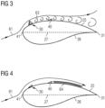
- Figure 3 shows the aerodynamic device 30 in a first protruded configuration.
- the aerodynamic device 30 deviates the airflow 61 which is flowing from the leading edge 41 to the trailing edge 31 of the rotor blade.
- the aerodynamic device 30 in the first protruded configuration induces stall. This is visualized with relatively large vortices 63 downstream of the aerodynamic device 30. A consequence of the induced stall is a decrease in lift of the rotor blade and, consequently, a reduced loading of the rotor blade and related components of the wind turbine.
- Figure 4 shows the aerodynamic device 30 in a second retracted configuration, i.e. moved downwards towards the surface of the rotor blade 20.
- the aerodynamic device 30 By operating the actuator, i.e. the pressure line 53, of the aerodynamic device 30, the aerodynamic device 30 can be moved between the first protruded configuration and the second retracted configuration in order to vary the aerodynamic properties of the blade as desired and requested when operating the wind turbine 10.
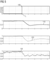
- FIG. 5 the plot shows an activation signal 100 for the aerodynamic device 30, which is being activated in the first protruded configuration at an activation time T1.
- the plots 110, 120, 130 show a desired normalized temporal course of three operational values of the wind turbine 10, namely the turbine power production 110, the rotor speed 120 and the rotor thrust 130, respectively.
- the desired temporal courses of the operational values are registered during a non-faulty time interval of the aerodynamic device 30.
- the desired temporal courses of the operational values are calculated offline, for example according to theoretical models.
- the desired normalized temporal courses 110, 120, 130 may be therefore defined as expected values, when the aerodynamic device 30 is working correctly, without faults.
- the actual temporal courses of at least one of the desired operational values 110, 120, 130 of the wind turbine 10 are measured when activating or deactivating of the actuator of the aerodynamic device 30.
- the measured temporal courses are compared with the desired temporal courses of the operational values to derive an operative status of the aerodynamic device 30.
- the comparison involves calculating a difference between the measured temporal courses and the desired temporal courses.
- the deviation between the measured temporal courses and the desired temporal courses involves the calculation of typical error function, e.g. the simple moving average error function or the mean squared error function or the exponential error function.
- a plurality of operational values may be used in addition or instead of the above mentioned turbine power production 110, the rotor speed 120 and the rotor thrust 130, for example:
Landscapes
- Engineering & Computer Science (AREA)
- Life Sciences & Earth Sciences (AREA)
- Sustainable Development (AREA)
- Sustainable Energy (AREA)
- Chemical & Material Sciences (AREA)
- Combustion & Propulsion (AREA)
- Mechanical Engineering (AREA)
- General Engineering & Computer Science (AREA)
- Wind Motors (AREA)
Claims (7)
- Verfahren zum Detektieren des Betriebsstatus einer aerodynamischen Vorrichtung (30) zum Beeinflussen der Luftströmung (61), die von der Vorderkante (41) eines Rotorblatts (20) für eine Windturbine (10) zu der Hinterkante (31) des Rotorblatts (20) strömt, wobei die aerodynamische Vorrichtung (30) durch einen Aktuator zwischen einer ersten vorstehenden Konfiguration und einer zweiten zurückgezogenen Konfiguration beweglich ist, wobei das Verfahren die folgenden Schritte umfasst:- Messen eines zeitlichen Verlaufs eines Betriebswertes der Windturbine (10) während der Aktivierung und Deaktivierung des Aktuators der aerodynamischen Vorrichtung (30), wobei der Betriebswert durch die Anwesenheit und/oder Aktivierung und/oder Deaktivierung der aerodynamischen Vorrichtung (30) beeinflusst wird,- Vergleichen des gemessenen zeitlichen Verlaufs des Betriebswerts mit einem gewünschten zeitlichen Verlauf (110, 120, 130) eines Betriebswerts,- Ableiten eines Betriebsstatus der aerodynamischen Vorrichtung (30).
- Verfahren nach Anspruch 1, wobei der Betriebswert einer der folgenden Werte ist:- eine Leistungsabgabe der Windturbine (10),- eine Drehzahl eines Rotors und/oder elektrischen Generators der Windturbine (10),- ein Schub auf einem Rotor der Windturbine (10),- eine Belastung in einem Turm (11) oder Fundament oder Blatt (20) oder einer Maschinengondel (12) oder Nabe (13) der Windturbine (10),- ein Nickmoment auf einem Blatt (20) der Windturbine (10),- eine Last auf einem Blatt (20) der Windturbine (10),- eine Beschleunigung einer Maschinengondel (12) und/oder eines Turms (11) und/oder Rotorblatts (20) und/oder einer Nabe (13) der Windturbine (10),- eine Windgeschwindigkeit an der Maschinengondel (12) der Windturbine (10).
- Verfahren nach einem der vorhergehenden Ansprüche, wobei der gewünschte zeitliche Verlauf eines Betriebswerts während eines fehlerfreien Zeitintervalls der aerodynamischen Vorrichtung (30) aufgezeichnet wird.
- Verfahren nach einem der vorhergehenden Ansprüche, wobei der gewünschte zeitliche Verlauf eines Betriebswerts berechnet wird.
- Verfahren nach einem der vorhergehenden Ansprüche, wobei das Vergleichen des gemessenen zeitlichen Verlaufs des Betriebswertes mit einem gewünschten zeitlichen Verlauf eines Betriebswerts das Berechnen einer Differenz zwischen dem gemessenen zeitlichen Verlauf des Betriebswertes und dem gewünschten zeitlichen Verlauf umfasst.
- Verfahren nach einem der vorhergehenden Ansprüche, wobei das Messen eines zeitlichen Verlaufs eines Betriebswerts der Windturbine (10) kontinuierlich durchgeführt wird.
- Verfahren nach einem der Ansprüche 1 bis 5, wobei das Messen eines zeitlichen Verlaufs eines Betriebswerts der Windturbine (10) periodisch durchgeführt wird.
Applications Claiming Priority (2)
| Application Number | Priority Date | Filing Date | Title |
|---|---|---|---|
| EP18212391.9A EP3667082A1 (de) | 2018-12-13 | 2018-12-13 | Windturbinenschaufeldurchflussregulierung |
| PCT/EP2019/079826 WO2020120013A1 (en) | 2018-12-13 | 2019-10-31 | Wind turbine blade flow regulation |
Publications (3)
| Publication Number | Publication Date |
|---|---|
| EP3894698A1 EP3894698A1 (de) | 2021-10-20 |
| EP3894698C0 EP3894698C0 (de) | 2025-06-25 |
| EP3894698B1 true EP3894698B1 (de) | 2025-06-25 |
Family
ID=64665470
Family Applications (2)
| Application Number | Title | Priority Date | Filing Date |
|---|---|---|---|
| EP18212391.9A Withdrawn EP3667082A1 (de) | 2018-12-13 | 2018-12-13 | Windturbinenschaufeldurchflussregulierung |
| EP19801756.8A Active EP3894698B1 (de) | 2018-12-13 | 2019-10-31 | Windturbinenschaufeldurchflussregulierung |
Family Applications Before (1)
| Application Number | Title | Priority Date | Filing Date |
|---|---|---|---|
| EP18212391.9A Withdrawn EP3667082A1 (de) | 2018-12-13 | 2018-12-13 | Windturbinenschaufeldurchflussregulierung |
Country Status (5)
| Country | Link |
|---|---|
| US (1) | US11767822B2 (de) |
| EP (2) | EP3667082A1 (de) |
| CN (1) | CN113227571B (de) |
| ES (1) | ES3037852T3 (de) |
| WO (1) | WO2020120013A1 (de) |
Families Citing this family (3)
| Publication number | Priority date | Publication date | Assignee | Title |
|---|---|---|---|---|
| EP3667063A1 (de) * | 2018-12-13 | 2020-06-17 | Siemens Gamesa Renewable Energy A/S | Vorrichtung zur ableitung von feuchtigkeit in windturbinen |
| EP3719307A1 (de) * | 2019-04-01 | 2020-10-07 | Siemens Gamesa Renewable Energy A/S | Verteiltes system und verfahren zum erfassen der position und/oder geschwindigkeit eines rotorblattes während des betriebs einer windturbine |
| EP4390120A1 (de) * | 2022-12-22 | 2024-06-26 | Siemens Gamesa Renewable Energy A/S | Verfahren und vorrichtung zur computerimplementierten überwachung einer windturbine |
Family Cites Families (18)
| Publication number | Priority date | Publication date | Assignee | Title |
|---|---|---|---|---|
| AU4218285A (en) | 1984-04-26 | 1985-11-15 | Sir Henry Lawson-Tancred, Sons & Co. Ltd. | Wind turbine blades |
| DE3913505A1 (de) | 1989-04-25 | 1989-11-16 | Astrid Holzem | Fluegel mit aerodynamischer bremse fuer windkraftmaschinen |
| DK174261B1 (da) | 2000-09-29 | 2002-10-21 | Bonus Energy As | Anordning til brug ved regulering af luftstrømning omkring en vindmøllevinge |
| DK200300670A (da) | 2003-05-05 | 2004-11-06 | Lm Glasfiber As | Vindmölleving med opdriftsregulerende organer |
| CN102165185B (zh) | 2008-08-29 | 2013-07-24 | 维斯塔斯风力系统有限公司 | 风轮机叶片中的控制系统 |
| US8186950B2 (en) * | 2008-12-23 | 2012-05-29 | General Electric Company | Aerodynamic device for detection of wind turbine blade operation |
| EP2548800A1 (de) * | 2011-07-22 | 2013-01-23 | LM Wind Power A/S | Verfahren zum Nachrüsten von Wirbelerzeugern auf einer Windturbinenschaufel |
| DE102011116961B4 (de) * | 2011-10-26 | 2024-06-27 | Weidmüller Monitoring Systems Gmbh | Verfahren zur Bestimmung einer mechanischen Beschädigung eines Rotorblatts einer Windenergieanlage |
| CN106414999A (zh) * | 2014-05-06 | 2017-02-15 | 西门子公司 | 用于风力机转子叶片的降噪装置 |
| DK178138B1 (en) * | 2014-07-16 | 2015-06-22 | Envision Energy | Vortex generator unit for a wind turbine blade |
| US10385826B2 (en) * | 2014-09-12 | 2019-08-20 | Ge Infrastructure Technology, Llc | Wind turbine air deflector system control |
| US10087912B2 (en) * | 2015-01-30 | 2018-10-02 | General Electric Company | Vortex generator for a rotor blade |
| ES2851340T3 (es) * | 2016-08-30 | 2021-09-06 | Siemens Gamesa Renewable Energy As | Control de la velocidad de rotación mediante la modificación del perfil de pala |
| DK3488101T3 (da) | 2016-08-30 | 2023-05-01 | Siemens Gamesa Renewable Energy As | Strømningsregulerende indretning til en vindmøllerotorvinge |
| WO2018162102A1 (en) | 2017-03-07 | 2018-09-13 | Siemens Wind Power A/S | Pressure supply system for a pneumatically activatable aerodynamic device of a rotor blade of a wind turbine |
| EP3577338B1 (de) | 2017-03-07 | 2024-08-07 | Siemens Gamesa Renewable Energy A/S | Sicherheitssystem für eine aerodynamische vorrichtung eines windturbinenrotorblatts |
| US20190072072A1 (en) * | 2017-09-06 | 2019-03-07 | Envision Energy Usa Ltd. | Variable speed control of wind turbine generator based on estimated torque |
| CN207278416U (zh) * | 2017-10-23 | 2018-04-27 | 大唐(朝阳)新能源有限公司 | 风机叶片 |
-
2018
- 2018-12-13 EP EP18212391.9A patent/EP3667082A1/de not_active Withdrawn
-
2019
- 2019-10-31 WO PCT/EP2019/079826 patent/WO2020120013A1/en not_active Ceased
- 2019-10-31 US US17/297,141 patent/US11767822B2/en active Active
- 2019-10-31 CN CN201980082635.1A patent/CN113227571B/zh active Active
- 2019-10-31 ES ES19801756T patent/ES3037852T3/es active Active
- 2019-10-31 EP EP19801756.8A patent/EP3894698B1/de active Active
Also Published As
| Publication number | Publication date |
|---|---|
| US20220018336A1 (en) | 2022-01-20 |
| US11767822B2 (en) | 2023-09-26 |
| EP3667082A1 (de) | 2020-06-17 |
| EP3894698C0 (de) | 2025-06-25 |
| CN113227571A (zh) | 2021-08-06 |
| ES3037852T3 (en) | 2025-10-07 |
| WO2020120013A1 (en) | 2020-06-18 |
| CN113227571B (zh) | 2024-09-03 |
| EP3894698A1 (de) | 2021-10-20 |
Similar Documents
| Publication | Publication Date | Title |
|---|---|---|
| US8827644B2 (en) | Wind turbine rotor blade | |
| DK178158B1 (en) | Wind turbine rotor blade with actuatable airfoil passages | |
| EP2122164B1 (de) | Windturbinenschaufel mit auftriebsregelmittel in form von schlitzen und löchern | |
| EP3577339B1 (de) | Druckversorgungssystem für eine pneumatisch aktivierbare aerodynamische vorrichtung eines rotorblatts einer windturbine | |
| EP3894698B1 (de) | Windturbinenschaufeldurchflussregulierung | |
| EP3029317B1 (de) | Verfahren und vorrichtung zur verringerung von ermüdung und böenlasten an windturbinenblättern | |
| EP2626551A2 (de) | Verfahren zur Steuerung einer Windturbine | |
| CN115667703A (zh) | 使用活动转子叶片附加装置的转子叶片偏转控制 | |
| EP3870845B1 (de) | Dämpfung von schwingungen in einer windturbine | |
| CN113167230B (zh) | 检测风力涡轮机转子叶片调节故障 | |
| EP2715122A2 (de) | Verfahren zur steuerung einer windturbine | |
| US20220025867A1 (en) | Wind turbine blade flow regulation | |
| EP3667065A1 (de) | Beseitigung von schwingungen in windturbinenschaufeln | |
| EP3580453B1 (de) | Verfahren und system zum steuern einer windturbine | |
| EP4100645B1 (de) | Verringerung der aerodynamischen belastung bei der schaufelmontage und -wartung einer windturbine | |
| EP3867526B1 (de) | Windturbinenschaufeldurchflussregulierung | |
| EP4146931B1 (de) | Betriebsverfahren für windturbinen zur reaktion auf netzstörungen | |
| EP3832127A1 (de) | Windturbinenschaufeldurchflussregulierung |
Legal Events
| Date | Code | Title | Description |
|---|---|---|---|
| STAA | Information on the status of an ep patent application or granted ep patent |
Free format text: STATUS: UNKNOWN |
|
| STAA | Information on the status of an ep patent application or granted ep patent |
Free format text: STATUS: THE INTERNATIONAL PUBLICATION HAS BEEN MADE |
|
| PUAI | Public reference made under article 153(3) epc to a published international application that has entered the european phase |
Free format text: ORIGINAL CODE: 0009012 |
|
| STAA | Information on the status of an ep patent application or granted ep patent |
Free format text: STATUS: REQUEST FOR EXAMINATION WAS MADE |
|
| 17P | Request for examination filed |
Effective date: 20210713 |
|
| AK | Designated contracting states |
Kind code of ref document: A1 Designated state(s): AL AT BE BG CH CY CZ DE DK EE ES FI FR GB GR HR HU IE IS IT LI LT LU LV MC MK MT NL NO PL PT RO RS SE SI SK SM TR |
|
| DAV | Request for validation of the european patent (deleted) | ||
| DAX | Request for extension of the european patent (deleted) | ||
| STAA | Information on the status of an ep patent application or granted ep patent |
Free format text: STATUS: EXAMINATION IS IN PROGRESS |
|
| 17Q | First examination report despatched |
Effective date: 20230629 |
|
| GRAP | Despatch of communication of intention to grant a patent |
Free format text: ORIGINAL CODE: EPIDOSNIGR1 |
|
| STAA | Information on the status of an ep patent application or granted ep patent |
Free format text: STATUS: GRANT OF PATENT IS INTENDED |
|
| INTG | Intention to grant announced |
Effective date: 20250220 |
|
| GRAS | Grant fee paid |
Free format text: ORIGINAL CODE: EPIDOSNIGR3 |
|
| GRAA | (expected) grant |
Free format text: ORIGINAL CODE: 0009210 |
|
| STAA | Information on the status of an ep patent application or granted ep patent |
Free format text: STATUS: THE PATENT HAS BEEN GRANTED |
|
| AK | Designated contracting states |
Kind code of ref document: B1 Designated state(s): AL AT BE BG CH CY CZ DE DK EE ES FI FR GB GR HR HU IE IS IT LI LT LU LV MC MK MT NL NO PL PT RO RS SE SI SK SM TR |
|
| REG | Reference to a national code |
Ref country code: GB Ref legal event code: FG4D |
|
| REG | Reference to a national code |
Ref country code: CH Ref legal event code: EP |
|
| REG | Reference to a national code |
Ref country code: DE Ref legal event code: R096 Ref document number: 602019071645 Country of ref document: DE |
|
| REG | Reference to a national code |
Ref country code: CH Ref legal event code: EP |
|
| REG | Reference to a national code |
Ref country code: IE Ref legal event code: FG4D |
|
| U01 | Request for unitary effect filed |
Effective date: 20250719 |
|
| U07 | Unitary effect registered |
Designated state(s): AT BE BG DE DK EE FI FR IT LT LU LV MT NL PT RO SE SI Effective date: 20250725 |
|
| REG | Reference to a national code |
Ref country code: ES Ref legal event code: FG2A Ref document number: 3037852 Country of ref document: ES Kind code of ref document: T3 Effective date: 20251007 |
|
| PG25 | Lapsed in a contracting state [announced via postgrant information from national office to epo] |
Ref country code: NO Free format text: LAPSE BECAUSE OF FAILURE TO SUBMIT A TRANSLATION OF THE DESCRIPTION OR TO PAY THE FEE WITHIN THE PRESCRIBED TIME-LIMIT Effective date: 20250925 Ref country code: GR Free format text: LAPSE BECAUSE OF FAILURE TO SUBMIT A TRANSLATION OF THE DESCRIPTION OR TO PAY THE FEE WITHIN THE PRESCRIBED TIME-LIMIT Effective date: 20250926 |
|
| PGFP | Annual fee paid to national office [announced via postgrant information from national office to epo] |
Ref country code: GB Payment date: 20250901 Year of fee payment: 7 |
|
| PG25 | Lapsed in a contracting state [announced via postgrant information from national office to epo] |
Ref country code: HR Free format text: LAPSE BECAUSE OF FAILURE TO SUBMIT A TRANSLATION OF THE DESCRIPTION OR TO PAY THE FEE WITHIN THE PRESCRIBED TIME-LIMIT Effective date: 20250625 |
|
| PG25 | Lapsed in a contracting state [announced via postgrant information from national office to epo] |
Ref country code: RS Free format text: LAPSE BECAUSE OF FAILURE TO SUBMIT A TRANSLATION OF THE DESCRIPTION OR TO PAY THE FEE WITHIN THE PRESCRIBED TIME-LIMIT Effective date: 20250925 |
|
| U20 | Renewal fee for the european patent with unitary effect paid |
Year of fee payment: 7 Effective date: 20251031 |
|
| PG25 | Lapsed in a contracting state [announced via postgrant information from national office to epo] |
Ref country code: IS Free format text: LAPSE BECAUSE OF FAILURE TO SUBMIT A TRANSLATION OF THE DESCRIPTION OR TO PAY THE FEE WITHIN THE PRESCRIBED TIME-LIMIT Effective date: 20251025 |
|
| PG25 | Lapsed in a contracting state [announced via postgrant information from national office to epo] |
Ref country code: SM Free format text: LAPSE BECAUSE OF FAILURE TO SUBMIT A TRANSLATION OF THE DESCRIPTION OR TO PAY THE FEE WITHIN THE PRESCRIBED TIME-LIMIT Effective date: 20250625 |
|
| PG25 | Lapsed in a contracting state [announced via postgrant information from national office to epo] |
Ref country code: CZ Free format text: LAPSE BECAUSE OF FAILURE TO SUBMIT A TRANSLATION OF THE DESCRIPTION OR TO PAY THE FEE WITHIN THE PRESCRIBED TIME-LIMIT Effective date: 20250625 |
|
| PG25 | Lapsed in a contracting state [announced via postgrant information from national office to epo] |
Ref country code: PL Free format text: LAPSE BECAUSE OF FAILURE TO SUBMIT A TRANSLATION OF THE DESCRIPTION OR TO PAY THE FEE WITHIN THE PRESCRIBED TIME-LIMIT Effective date: 20250625 |
|
| PG25 | Lapsed in a contracting state [announced via postgrant information from national office to epo] |
Ref country code: SK Free format text: LAPSE BECAUSE OF FAILURE TO SUBMIT A TRANSLATION OF THE DESCRIPTION OR TO PAY THE FEE WITHIN THE PRESCRIBED TIME-LIMIT Effective date: 20250625 |
|
| PGFP | Annual fee paid to national office [announced via postgrant information from national office to epo] |
Ref country code: ES Payment date: 20251118 Year of fee payment: 7 |