EP4100645B1 - Verringerung der aerodynamischen belastung bei der schaufelmontage und -wartung einer windturbine - Google Patents
Verringerung der aerodynamischen belastung bei der schaufelmontage und -wartung einer windturbine Download PDFInfo
- Publication number
- EP4100645B1 EP4100645B1 EP21711784.5A EP21711784A EP4100645B1 EP 4100645 B1 EP4100645 B1 EP 4100645B1 EP 21711784 A EP21711784 A EP 21711784A EP 4100645 B1 EP4100645 B1 EP 4100645B1
- Authority
- EP
- European Patent Office
- Prior art keywords
- wind turbine
- rotor blade
- aerodynamic
- blade
- service
- Prior art date
- Legal status (The legal status is an assumption and is not a legal conclusion. Google has not performed a legal analysis and makes no representation as to the accuracy of the status listed.)
- Active
Links
Images

Classifications
-
- F—MECHANICAL ENGINEERING; LIGHTING; HEATING; WEAPONS; BLASTING
- F03—MACHINES OR ENGINES FOR LIQUIDS; WIND, SPRING, OR WEIGHT MOTORS; PRODUCING MECHANICAL POWER OR A REACTIVE PROPULSIVE THRUST, NOT OTHERWISE PROVIDED FOR
- F03D—WIND MOTORS
- F03D13/00—Assembly, mounting or commissioning of wind motors; Arrangements specially adapted for transporting wind motor components
- F03D13/10—Assembly of wind motors; Arrangements for erecting wind motors
-
- F—MECHANICAL ENGINEERING; LIGHTING; HEATING; WEAPONS; BLASTING
- F03—MACHINES OR ENGINES FOR LIQUIDS; WIND, SPRING, OR WEIGHT MOTORS; PRODUCING MECHANICAL POWER OR A REACTIVE PROPULSIVE THRUST, NOT OTHERWISE PROVIDED FOR
- F03D—WIND MOTORS
- F03D1/00—Wind motors with rotation axis substantially parallel to the air flow entering the rotor
- F03D1/06—Rotors
- F03D1/065—Rotors characterised by their construction elements
- F03D1/0675—Rotors characterised by their construction elements of the blades
-
- F—MECHANICAL ENGINEERING; LIGHTING; HEATING; WEAPONS; BLASTING
- F03—MACHINES OR ENGINES FOR LIQUIDS; WIND, SPRING, OR WEIGHT MOTORS; PRODUCING MECHANICAL POWER OR A REACTIVE PROPULSIVE THRUST, NOT OTHERWISE PROVIDED FOR
- F03D—WIND MOTORS
- F03D80/00—Details, components or accessories not provided for in groups F03D1/00 - F03D17/00
- F03D80/50—Maintenance or repair
-
- F—MECHANICAL ENGINEERING; LIGHTING; HEATING; WEAPONS; BLASTING
- F05—INDEXING SCHEMES RELATING TO ENGINES OR PUMPS IN VARIOUS SUBCLASSES OF CLASSES F01-F04
- F05B—INDEXING SCHEME RELATING TO WIND, SPRING, WEIGHT, INERTIA OR LIKE MOTORS, TO MACHINES OR ENGINES FOR LIQUIDS COVERED BY SUBCLASSES F03B, F03D AND F03G
- F05B2240/00—Components
- F05B2240/20—Rotors
- F05B2240/30—Characteristics of rotor blades, i.e. of any element transforming dynamic fluid energy to or from rotational energy and being attached to a rotor
- F05B2240/305—Flaps, slats or spoilers
- F05B2240/3052—Flaps, slats or spoilers adjustable
-
- Y—GENERAL TAGGING OF NEW TECHNOLOGICAL DEVELOPMENTS; GENERAL TAGGING OF CROSS-SECTIONAL TECHNOLOGIES SPANNING OVER SEVERAL SECTIONS OF THE IPC; TECHNICAL SUBJECTS COVERED BY FORMER USPC CROSS-REFERENCE ART COLLECTIONS [XRACs] AND DIGESTS
- Y02—TECHNOLOGIES OR APPLICATIONS FOR MITIGATION OR ADAPTATION AGAINST CLIMATE CHANGE
- Y02E—REDUCTION OF GREENHOUSE GAS [GHG] EMISSIONS, RELATED TO ENERGY GENERATION, TRANSMISSION OR DISTRIBUTION
- Y02E10/00—Energy generation through renewable energy sources
- Y02E10/70—Wind energy
- Y02E10/72—Wind turbines with rotation axis in wind direction
Definitions
- the present invention relates to a method for reducing the aerodynamic load during blade installation and service in a wind turbine.
- Blade loads during installation may drive requirement on the number of blade bolts needed before removing the crane.
- Blade loads during service may drive requirement on rotor components, such as rotor lock and pitch lock.
- the blade may be installed with an alignment to the wind trying to minimize the aerodynamic load, or the rotor may be oriented such that aerodynamic blade loads are reduced. Further, temporary add-on like stall strips may be installed on the blade during installation.
- EP 2 708 734 A1 discloses a wind turbine blade comprising one or more flow disturbing devices for provoking air flow separation arranged on the suction side of the blade, wherein the flow disturbing device is removable.
- EP 3 225 834 A1 describe a method which comprises the steps of attaching a temporary cover on the rotor blade for covering at least a part of the aerodynamic device before lifting the rotor blade to the top of the tower of the wind turbine, and detaching the cover subsequently.
- a method for installing or servicing a wind turbine including at least a rotor blade having a plurality of aerodynamic devices for influencing the airflow flowing from the leading edge of the rotor blade of the wind turbine to the trailing edge of the rotor blade.
- the method comprising the steps of:
- the phase of activating the aerodynamic devices is performed before or during the phase of installing the rotor blade or performing a service on the wind turbine.
- the phase of deactivating the aerodynamic devices is performed during or after the phase of installing the rotor blade or performing a service on the wind turbine.
- the method of the present invention allows activation of the aerodynamic devices to change the blade shape during installing or servicing a wind turbine.
- the change in the blade shape reduces the aerodynamic forces developed by the wind flowing on the blade.
- Lower aerodynamic forces lead to lower blade oscillation and lower blade loads, that the installation tools (e.g. cranes) or the wind turbine have to compensate or carry.
- Such aerodynamic devices are integrated in the rotor blades, not a temporary add-on like stall strips. Therefore, it is not needed to add it before the installation/service and remove it after installation/service.
- the above method makes, with respect to the prior art installation and service:
- Lower blade loads during installation reduces requirement on the number of blade bolts needed before removing the crane.
- Lower blade loads during service reduce requirement on rotor components, such as rotor lock and pitch lock.
- the aerodynamic devices are flaps, i.e. aerodynamic devices installed at the trailing edge of the rotor blade.
- the aerodynamic devices are spoilers, i.e. an aerodynamic device installed at the leading edge or in a position intermediate between the leading edge and the trailing edge of the rotor blade. Flaps and spoilers may be together provided on the rotor blade.
- the aerodynamic devices may be activated before the phase of installing the rotor blade or performing a service, for example before the lifting phase of the rotor blade.
- the aerodynamic devices may be activated during the installation of the rotor blade or performing a service, for example during the lifting phase of the rotor blade.
- each aerodynamic device is movable by an actuator between a first protruded configuration and a second retracted configuration, the aerodynamic devices being in the first protruded configuration when activated and in the second retracted configuration when deactivated.
- the aerodynamic devices may be deactivated after the phase of installing the rotor blade or performing a service on the wind turbine is terminated, for example after the rotor blade has been connected to the hub of the wind turbine.
- the aerodynamic devices may be deactivated during the installation of the rotor blade, for example during the lifting phase of the rotor blade.
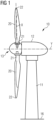
- FIG. 1 shows a conventional wind turbine 10 for generating electricity.
- the wind turbine 10 comprises a tower 11 which is mounted on the ground 16 at one end. At the opposite end of the tower 11 there is mounted a nacelle 12.
- the nacelle 12 is usually mounted rotatable with regard to the tower 11, which is referred to as comprising a yaw axis substantially perpendicular to the ground 16.
- the nacelle 12 usually accommodates the generator of the wind turbine and the gear box (if the wind turbine is a geared wind turbine).
- the wind turbine 10 comprises a hub 13 which is rotatable about a rotor axis Y.
- the terms axial, radial and circumferential in the following are made with reference to the rotor axis Y.
- the hub 13 is often described as being a part of a wind turbine rotor, wherein the wind turbine rotor is capable to rotate about the rotor axis Y and to transfer the rotational energy to an electrical generator (not shown).
- the wind turbine 1 further comprises at least one blade 20 (in the embodiment of Figure 1 , the wind rotor comprises three blades 20, of which only two blades 20 are visible) mounted on the hub 13.
- the blades 4 extend substantially radially with respect to the rotational axis Y.
- Each rotor blade 20 is usually mounted pivotable to the hub 13, in order to be pitched about respective pitch axes X. This improves the control of the wind turbine and in particular of the rotor blades by the possibility of modifying the direction at which the wind is hitting the rotor blades 20.
- Each rotor blade 20 is mounted to the hub 13 at its root section 21. The root section 21 is opposed to the tip section 22 of the rotor blade.
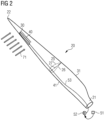
- FIG. 2 illustrates the rotor blade 20 comprising an aerodynamic device 30 in the form of an actuated spoiler.
- the rotor blade 20 furthermore comprises a plurality of aerofoil sections for generating lift.
- Each aerofoil section comprises a suction side 25 and a pressure side 26.
- the aerofoil shape of the aerofoil portion is symbolized by one aerofoil profile which is shown in Figure 2 and which illustrates the cross-sectional shape of the rotor blade at this spanwise position.
- the suction side 25 is divided or separated from the pressure side 26 by a chord line 27 which connects a leading edge 41 with a trailing edge 31 of the rotor blade 20.
- the aerodynamic device 30 in Figure 2 is movable by means of a pressure line 53 connected to a pneumatic actuator 34.
- the pneumatic actuator 34 is realized as a hose.
- the hose 34 comprises an elastic outer skin, such that it can inflate and deflate reversibly and during many cycles when operated by means of the pressure line 53.
- the pressure line 53 is comprised in a pressure supply system 52 and controlled by a control unit 51.
- the pressure supply system 52 provides pressurized air or other pressurized gas, to the pneumatic actuator 34.
- pressurized fluid not only implies positive pressure but also negative pressure, wherein fluid is sucked (or “drawn") out of the pneumatic actuator 34.
- the pressure line 53 could be in practice realized as tubes or pipes which do not significantly change their volume.
- the control unit 51 is responsible for setting a specific pressure at the pressure supply system 52 which subsequently leads to a certain predetermined pressure at the pneumatic actuator 34. By controlling the pressure of the pressurized air, the pneumatic actuator 34 is operated between an inflated and a deflated configuration.
- Any of the control unit 51 and the pressure supply system 52 may be located in the root section 21 of the rotor blade 20 or placed elsewhere in the wind turbine, such as e.g. in the hub 13 of the wind turbine 10 or in the nacelle 12 or in the tower 11.
- the rotor blade 20 additionally comprises a flow regulating unit 40 comprising multiple pairs of vortex generators.
- the flow regulating unit 40 are arranged on the suction side 25 of the blade 20 between the aerodynamic device 30 and the the trailing edge 31.
- the flow regulating unit 40 may be arranged on the suction side 25 of the blade 20 between the leading edge 41 and the aerodynamic device 30.
- the flow regulating unit 40 may be not present and only the aerodynamic device 30 may be used to regulate the flow on the surface of the blade 20.
- the blade 20 may comprise a plurality of aerodynamic devices 30.
- the aerodynamic device 30 may be configured as a trailing edge flap.
- the blade 20 may comprise a plurality of aerodynamic devices 30 including flaps and spoilers.
- Figure 3 shows the aerodynamic device 30 in a first protruded configuration, corresponding to an inflated configuration of the pneumatic actuator 34.
- the aerodynamic device 30 deviates the airflow 71 which is flowing from the leading edge 41 to the trailing edge 31 of the rotor blade.
- the aerodynamic device 30 in the first protruded configuration induces stall. This is visualized with relatively large vortices 63 downstream of the aerodynamic device 30.
- a consequence of the induced stall is a decrease in lift of the rotor blade and, consequently, a reduced loading of the rotor blade and related components of the wind turbine.
- Figure 4 shows the aerodynamic device 30 in a second retracted configuration, i.e. moved downwards towards the surface of the rotor blade 20, corresponding to a deflated configuration of the pneumatic actuator 34.
- the airflow 71 flowing across the aerodynamic device 30 remains attached to the surface of the rotor blade 20, thus that no flow separation, i.e. stall, occurs.
- the lift of the rotor blade increases.
- Re-energizing vortices 64 are generated in the boundary layer by the vortex generators 40, which have the effect of helping to increase the lift. As a result, the highest lift values can be achieved.
- the aerodynamic device 30 By operating the pneumatic actuator 34 of the aerodynamic device 30 through the pressure line 53, the aerodynamic device 30 can be moved between the first protruded configuration and the second retracted configuration in order to vary the aerodynamic properties of the blade as desired and requested when installing or servicing the wind turbine 10.
- the method 100 comprises a first step 110 of activating the aerodynamic device 30 at the beginning or during the lift and installation of the rotor blade 20.
- the aerodynamic device 30 is activated to reach the first protruded configuration.
- the activation of the aerodynamic device 30 changes the blade shape.
- the change in the blade shape reduces the aerodynamic forces developed by the wind flowing on the rotor blade 20.
- the rotor blade 20 is installed on the hub 13.
- the aerodynamic device 30 is deactivated, i.e. the aerodynamic device 30 is brought to the second retracted configuration.
- the method 100 comprises a first step 110 of activating the aerodynamic device 30 at the beginning or during the service procedure.
- the aerodynamic device 30 is activated to reach the first protruded configuration.
- the activation of the aerodynamic device 30 changes the blade shape.
- the change in the blade shape reduces the aerodynamic forces developed by the wind flowing on the rotor blade 20.
- the service is performed.
- the aerodynamic device 30 is deactivated, i.e. the aerodynamic device 30 is brought to the second retracted configuration.
- the first phase of activating 110 the aerodynamic devices 30 and/or the third phase of deactivating 130 the aerodynamic devices 30 are performed during the phase of installing 120 the rotor blade 20 or performing a service on the wind turbine.
- the aerodynamic devices 30 may be activated and/or deactivated during a phase of lifting a rotor blade 20 towards the hub 13, depending on the conditions (intensity and direction) of the wind.
Landscapes
- Engineering & Computer Science (AREA)
- Life Sciences & Earth Sciences (AREA)
- Sustainable Development (AREA)
- Sustainable Energy (AREA)
- Chemical & Material Sciences (AREA)
- Combustion & Propulsion (AREA)
- Mechanical Engineering (AREA)
- General Engineering & Computer Science (AREA)
- Wind Motors (AREA)
Claims (4)
- Verfahren (100) zum Installieren oder Warten einer Windenergieanlage (10), die mindestens ein Rotorblatt (20) mit einer Mehrzahl von aerodynamischen Vorrichtungen (30) zum Beeinflussen der Luftströmung (61) umfasst, die von der Vorderkante (41) des Rotorblatts (20) der Windenergieanlage (10) zur Hinterkante (31) des Rotorblatts (20) strömt, wobei das Verfahren die folgenden Schritte umfasst:- Aktivieren (110) der aerodynamischen Vorrichtungen (30),- Installieren (120) des Rotorblatts (20) oder Durchführen einer Wartung an der Windenergieanlage,- Deaktivieren (130) der aerodynamischen Vorrichtungen (30),wobei die Phase des Aktivierens (110) der aerodynamischen Vorrichtungen (30) vor oder während der Phase des Installierens (120) des Rotorblatts (20) oder Durchführens einer Wartung an der Windenergieanlage durchgeführt wird und die Phase des Deaktivierens (130) der aerodynamischen Vorrichtungen (30) während oder nach der Phase des Installierens (120) des Rotorblatts (20) oder Durchführens einer Wartung an der Windenergieanlage durchgeführt wird.
- Verfahren (100) nach Anspruch 1, wobei die aerodynamischen Vorrichtungen (30) bei Installieren der Windenergieanlage (10) zu Beginn einer Hebephase mindestens eines Rotorblatts (20) oder während der Hebephase mindestens eines Rotorblatts (20) aktiviert werden.
- Verfahren (100) nach Anspruch 1 oder 2, wobei die aerodynamischen Vorrichtungen (30) bei Installieren der Windenergieanlage (10) am Ende einer Hebephase mindestens eines Rotorblatts (20) oder während der Hebephase mindestens eines Rotorblatts (20) deaktiviert werden.
- Verfahren (100) nach einem der vorhergehenden Ansprüche, wobei jede aerodynamische Vorrichtung (30) durch einen Aktuator zwischen einer ersten hervorstehenden Auslegung und einer zweiten eingezogenen Auslegung beweglich ist, wobei sich die aerodynamischen Vorrichtungen (30) in der ersten hervorstehenden Auslegung befinden, wenn sie aktiviert sind, und in der zweiten eingezogenen Auslegung, wenn sie deaktiviert sind.
Applications Claiming Priority (2)
| Application Number | Priority Date | Filing Date | Title |
|---|---|---|---|
| EP20165448.0A EP3885572A1 (de) | 2020-03-25 | 2020-03-25 | Verringerung der aerodynamischen belastung bei der schaufelmontage und -wartung einer windturbine |
| PCT/EP2021/055356 WO2021190891A1 (en) | 2020-03-25 | 2021-03-03 | Aerodynamic load reduction during blade installation and service in a wind turbine |
Publications (2)
| Publication Number | Publication Date |
|---|---|
| EP4100645A1 EP4100645A1 (de) | 2022-12-14 |
| EP4100645B1 true EP4100645B1 (de) | 2024-04-03 |
Family
ID=69960533
Family Applications (2)
| Application Number | Title | Priority Date | Filing Date |
|---|---|---|---|
| EP20165448.0A Withdrawn EP3885572A1 (de) | 2020-03-25 | 2020-03-25 | Verringerung der aerodynamischen belastung bei der schaufelmontage und -wartung einer windturbine |
| EP21711784.5A Active EP4100645B1 (de) | 2020-03-25 | 2021-03-03 | Verringerung der aerodynamischen belastung bei der schaufelmontage und -wartung einer windturbine |
Family Applications Before (1)
| Application Number | Title | Priority Date | Filing Date |
|---|---|---|---|
| EP20165448.0A Withdrawn EP3885572A1 (de) | 2020-03-25 | 2020-03-25 | Verringerung der aerodynamischen belastung bei der schaufelmontage und -wartung einer windturbine |
Country Status (6)
| Country | Link |
|---|---|
| US (1) | US20230138124A1 (de) |
| EP (2) | EP3885572A1 (de) |
| CN (1) | CN115280013A (de) |
| DK (1) | DK4100645T3 (de) |
| ES (1) | ES2980589T3 (de) |
| WO (1) | WO2021190891A1 (de) |
Families Citing this family (1)
| Publication number | Priority date | Publication date | Assignee | Title |
|---|---|---|---|---|
| EP4008901A1 (de) * | 2020-12-03 | 2022-06-08 | Siemens Gamesa Renewable Energy A/S | Lastminderungsanordnung |
Citations (2)
| Publication number | Priority date | Publication date | Assignee | Title |
|---|---|---|---|---|
| EP2708734B1 (de) * | 2012-09-13 | 2016-11-09 | ALSTOM Renewable Technologies | Windturbinenschaufel und Verfahren zum Transportieren, Aufbewahren und Installieren von Windturbinenschaufeln |
| EP3225834B1 (de) * | 2016-03-31 | 2019-11-27 | Siemens Gamesa Renewable Energy A/S | Verringerung der belastung eines windturbinenrotorblatts während der installation |
Family Cites Families (7)
| Publication number | Priority date | Publication date | Assignee | Title |
|---|---|---|---|---|
| DK200300670A (da) * | 2003-05-05 | 2004-11-06 | Lm Glasfiber As | Vindmölleving med opdriftsregulerende organer |
| PT2007981T (pt) * | 2006-04-02 | 2021-02-11 | Wobben Properties Gmbh | Turbina eólica com pá esbelta |
| US8167554B2 (en) * | 2011-01-28 | 2012-05-01 | General Electric Corporation | Actuatable surface features for wind turbine rotor blades |
| DE102011111967B3 (de) * | 2011-08-31 | 2013-01-10 | Nordex Energy Gmbh | Gurtsystem zur Einzelblattmontage eines Rotorblattes oder zur Sternmontage eines Rotors an einer Windenergieanlage sowie Verfahren hierzu |
| US8834127B2 (en) * | 2011-09-09 | 2014-09-16 | General Electric Company | Extension for rotor blade in wind turbine |
| US20150211487A1 (en) * | 2014-01-27 | 2015-07-30 | Siemens Aktiengesellschaft | Dual purpose slat-spoiler for wind turbine blade |
| DK3488101T3 (da) * | 2016-08-30 | 2023-05-01 | Siemens Gamesa Renewable Energy As | Strømningsregulerende indretning til en vindmøllerotorvinge |
-
2020
- 2020-03-25 EP EP20165448.0A patent/EP3885572A1/de not_active Withdrawn
-
2021
- 2021-03-03 CN CN202180023874.7A patent/CN115280013A/zh active Pending
- 2021-03-03 ES ES21711784T patent/ES2980589T3/es active Active
- 2021-03-03 DK DK21711784.5T patent/DK4100645T3/da active
- 2021-03-03 US US17/912,348 patent/US20230138124A1/en not_active Abandoned
- 2021-03-03 WO PCT/EP2021/055356 patent/WO2021190891A1/en not_active Ceased
- 2021-03-03 EP EP21711784.5A patent/EP4100645B1/de active Active
Patent Citations (2)
| Publication number | Priority date | Publication date | Assignee | Title |
|---|---|---|---|---|
| EP2708734B1 (de) * | 2012-09-13 | 2016-11-09 | ALSTOM Renewable Technologies | Windturbinenschaufel und Verfahren zum Transportieren, Aufbewahren und Installieren von Windturbinenschaufeln |
| EP3225834B1 (de) * | 2016-03-31 | 2019-11-27 | Siemens Gamesa Renewable Energy A/S | Verringerung der belastung eines windturbinenrotorblatts während der installation |
Also Published As
| Publication number | Publication date |
|---|---|
| WO2021190891A1 (en) | 2021-09-30 |
| BR112022018208A2 (pt) | 2022-10-25 |
| EP3885572A1 (de) | 2021-09-29 |
| ES2980589T3 (es) | 2024-10-02 |
| US20230138124A1 (en) | 2023-05-04 |
| EP4100645A1 (de) | 2022-12-14 |
| CN115280013A (zh) | 2022-11-01 |
| DK4100645T3 (da) | 2024-05-21 |
Similar Documents
| Publication | Publication Date | Title |
|---|---|---|
| EP3577339B1 (de) | Druckversorgungssystem für eine pneumatisch aktivierbare aerodynamische vorrichtung eines rotorblatts einer windturbine | |
| EP4179196B1 (de) | Rotorblattanordnung zur abschwächung strömungsabrissbedingter schwingungen | |
| EP4100645B1 (de) | Verringerung der aerodynamischen belastung bei der schaufelmontage und -wartung einer windturbine | |
| EP3870845B1 (de) | Dämpfung von schwingungen in einer windturbine | |
| EP3894698B1 (de) | Windturbinenschaufeldurchflussregulierung | |
| EP4123160B1 (de) | Vorrichtungen und verfahren zur abschwächung von schwingungen in rotorblätter von windkraftanlagen | |
| EP3667065A1 (de) | Beseitigung von schwingungen in windturbinenschaufeln | |
| EP4259925B1 (de) | Aerodynamisches element für ein rotorblatt einer windturbine | |
| EP4305297B1 (de) | Betrieb einer windkraftanlage zur nachlaufregelung | |
| EP4093966B1 (de) | Verfahren und vorrichtung zur steuerung einer windturbine zur geräuschminderung | |
| BR112022018208B1 (pt) | Método para instalar ou fazer manutenção em uma turbina eólica | |
| US12066008B2 (en) | Device for controlling humidity in wind turbines | |
| EP3832127A1 (de) | Windturbinenschaufeldurchflussregulierung |
Legal Events
| Date | Code | Title | Description |
|---|---|---|---|
| STAA | Information on the status of an ep patent application or granted ep patent |
Free format text: STATUS: UNKNOWN |
|
| STAA | Information on the status of an ep patent application or granted ep patent |
Free format text: STATUS: THE INTERNATIONAL PUBLICATION HAS BEEN MADE |
|
| PUAI | Public reference made under article 153(3) epc to a published international application that has entered the european phase |
Free format text: ORIGINAL CODE: 0009012 |
|
| STAA | Information on the status of an ep patent application or granted ep patent |
Free format text: STATUS: REQUEST FOR EXAMINATION WAS MADE |
|
| 17P | Request for examination filed |
Effective date: 20220905 |
|
| AK | Designated contracting states |
Kind code of ref document: A1 Designated state(s): AL AT BE BG CH CY CZ DE DK EE ES FI FR GB GR HR HU IE IS IT LI LT LU LV MC MK MT NL NO PL PT RO RS SE SI SK SM TR |
|
| DAV | Request for validation of the european patent (deleted) | ||
| DAX | Request for extension of the european patent (deleted) | ||
| GRAP | Despatch of communication of intention to grant a patent |
Free format text: ORIGINAL CODE: EPIDOSNIGR1 |
|
| STAA | Information on the status of an ep patent application or granted ep patent |
Free format text: STATUS: GRANT OF PATENT IS INTENDED |
|
| INTG | Intention to grant announced |
Effective date: 20231012 |
|
| GRAS | Grant fee paid |
Free format text: ORIGINAL CODE: EPIDOSNIGR3 |
|
| GRAA | (expected) grant |
Free format text: ORIGINAL CODE: 0009210 |
|
| STAA | Information on the status of an ep patent application or granted ep patent |
Free format text: STATUS: THE PATENT HAS BEEN GRANTED |
|
| AK | Designated contracting states |
Kind code of ref document: B1 Designated state(s): AL AT BE BG CH CY CZ DE DK EE ES FI FR GB GR HR HU IE IS IT LI LT LU LV MC MK MT NL NO PL PT RO RS SE SI SK SM TR |
|
| REG | Reference to a national code |
Ref country code: CH Ref legal event code: EP |
|
| REG | Reference to a national code |
Ref country code: IE Ref legal event code: FG4D |
|
| REG | Reference to a national code |
Ref country code: DE Ref legal event code: R096 Ref document number: 602021011319 Country of ref document: DE |
|
| REG | Reference to a national code |
Ref country code: DK Ref legal event code: T3 Effective date: 20240513 |
|
| REG | Reference to a national code |
Ref country code: SE Ref legal event code: TRGR |
|
| REG | Reference to a national code |
Ref country code: LT Ref legal event code: MG9D |
|
| REG | Reference to a national code |
Ref country code: NL Ref legal event code: MP Effective date: 20240403 |
|
| REG | Reference to a national code |
Ref country code: AT Ref legal event code: MK05 Ref document number: 1672567 Country of ref document: AT Kind code of ref document: T Effective date: 20240403 |
|
| PG25 | Lapsed in a contracting state [announced via postgrant information from national office to epo] |
Ref country code: NL Free format text: LAPSE BECAUSE OF FAILURE TO SUBMIT A TRANSLATION OF THE DESCRIPTION OR TO PAY THE FEE WITHIN THE PRESCRIBED TIME-LIMIT Effective date: 20240403 |
|
| PG25 | Lapsed in a contracting state [announced via postgrant information from national office to epo] |
Ref country code: NL Free format text: LAPSE BECAUSE OF FAILURE TO SUBMIT A TRANSLATION OF THE DESCRIPTION OR TO PAY THE FEE WITHIN THE PRESCRIBED TIME-LIMIT Effective date: 20240403 |
|
| REG | Reference to a national code |
Ref country code: ES Ref legal event code: FG2A Ref document number: 2980589 Country of ref document: ES Kind code of ref document: T3 Effective date: 20241002 |
|
| PG25 | Lapsed in a contracting state [announced via postgrant information from national office to epo] |
Ref country code: IS Free format text: LAPSE BECAUSE OF FAILURE TO SUBMIT A TRANSLATION OF THE DESCRIPTION OR TO PAY THE FEE WITHIN THE PRESCRIBED TIME-LIMIT Effective date: 20240803 |
|
| PG25 | Lapsed in a contracting state [announced via postgrant information from national office to epo] |
Ref country code: BG Free format text: LAPSE BECAUSE OF FAILURE TO SUBMIT A TRANSLATION OF THE DESCRIPTION OR TO PAY THE FEE WITHIN THE PRESCRIBED TIME-LIMIT Effective date: 20240403 |
|
| PG25 | Lapsed in a contracting state [announced via postgrant information from national office to epo] |
Ref country code: HR Free format text: LAPSE BECAUSE OF FAILURE TO SUBMIT A TRANSLATION OF THE DESCRIPTION OR TO PAY THE FEE WITHIN THE PRESCRIBED TIME-LIMIT Effective date: 20240403 Ref country code: FI Free format text: LAPSE BECAUSE OF FAILURE TO SUBMIT A TRANSLATION OF THE DESCRIPTION OR TO PAY THE FEE WITHIN THE PRESCRIBED TIME-LIMIT Effective date: 20240403 |
|
| PG25 | Lapsed in a contracting state [announced via postgrant information from national office to epo] |
Ref country code: GR Free format text: LAPSE BECAUSE OF FAILURE TO SUBMIT A TRANSLATION OF THE DESCRIPTION OR TO PAY THE FEE WITHIN THE PRESCRIBED TIME-LIMIT Effective date: 20240704 |
|
| PG25 | Lapsed in a contracting state [announced via postgrant information from national office to epo] |
Ref country code: PT Free format text: LAPSE BECAUSE OF FAILURE TO SUBMIT A TRANSLATION OF THE DESCRIPTION OR TO PAY THE FEE WITHIN THE PRESCRIBED TIME-LIMIT Effective date: 20240805 |
|
| PG25 | Lapsed in a contracting state [announced via postgrant information from national office to epo] |
Ref country code: CZ Free format text: LAPSE BECAUSE OF FAILURE TO SUBMIT A TRANSLATION OF THE DESCRIPTION OR TO PAY THE FEE WITHIN THE PRESCRIBED TIME-LIMIT Effective date: 20240403 |
|
| PG25 | Lapsed in a contracting state [announced via postgrant information from national office to epo] |
Ref country code: AT Free format text: LAPSE BECAUSE OF FAILURE TO SUBMIT A TRANSLATION OF THE DESCRIPTION OR TO PAY THE FEE WITHIN THE PRESCRIBED TIME-LIMIT Effective date: 20240403 |
|
| PG25 | Lapsed in a contracting state [announced via postgrant information from national office to epo] |
Ref country code: PL Free format text: LAPSE BECAUSE OF FAILURE TO SUBMIT A TRANSLATION OF THE DESCRIPTION OR TO PAY THE FEE WITHIN THE PRESCRIBED TIME-LIMIT Effective date: 20240403 |
|
| PG25 | Lapsed in a contracting state [announced via postgrant information from national office to epo] |
Ref country code: LV Free format text: LAPSE BECAUSE OF FAILURE TO SUBMIT A TRANSLATION OF THE DESCRIPTION OR TO PAY THE FEE WITHIN THE PRESCRIBED TIME-LIMIT Effective date: 20240403 |
|
| PG25 | Lapsed in a contracting state [announced via postgrant information from national office to epo] |
Ref country code: PT Free format text: LAPSE BECAUSE OF FAILURE TO SUBMIT A TRANSLATION OF THE DESCRIPTION OR TO PAY THE FEE WITHIN THE PRESCRIBED TIME-LIMIT Effective date: 20240805 Ref country code: PL Free format text: LAPSE BECAUSE OF FAILURE TO SUBMIT A TRANSLATION OF THE DESCRIPTION OR TO PAY THE FEE WITHIN THE PRESCRIBED TIME-LIMIT Effective date: 20240403 Ref country code: NO Free format text: LAPSE BECAUSE OF FAILURE TO SUBMIT A TRANSLATION OF THE DESCRIPTION OR TO PAY THE FEE WITHIN THE PRESCRIBED TIME-LIMIT Effective date: 20240703 Ref country code: LV Free format text: LAPSE BECAUSE OF FAILURE TO SUBMIT A TRANSLATION OF THE DESCRIPTION OR TO PAY THE FEE WITHIN THE PRESCRIBED TIME-LIMIT Effective date: 20240403 Ref country code: IS Free format text: LAPSE BECAUSE OF FAILURE TO SUBMIT A TRANSLATION OF THE DESCRIPTION OR TO PAY THE FEE WITHIN THE PRESCRIBED TIME-LIMIT Effective date: 20240803 Ref country code: HR Free format text: LAPSE BECAUSE OF FAILURE TO SUBMIT A TRANSLATION OF THE DESCRIPTION OR TO PAY THE FEE WITHIN THE PRESCRIBED TIME-LIMIT Effective date: 20240403 Ref country code: GR Free format text: LAPSE BECAUSE OF FAILURE TO SUBMIT A TRANSLATION OF THE DESCRIPTION OR TO PAY THE FEE WITHIN THE PRESCRIBED TIME-LIMIT Effective date: 20240704 Ref country code: FI Free format text: LAPSE BECAUSE OF FAILURE TO SUBMIT A TRANSLATION OF THE DESCRIPTION OR TO PAY THE FEE WITHIN THE PRESCRIBED TIME-LIMIT Effective date: 20240403 Ref country code: CZ Free format text: LAPSE BECAUSE OF FAILURE TO SUBMIT A TRANSLATION OF THE DESCRIPTION OR TO PAY THE FEE WITHIN THE PRESCRIBED TIME-LIMIT Effective date: 20240403 Ref country code: BG Free format text: LAPSE BECAUSE OF FAILURE TO SUBMIT A TRANSLATION OF THE DESCRIPTION OR TO PAY THE FEE WITHIN THE PRESCRIBED TIME-LIMIT Effective date: 20240403 Ref country code: AT Free format text: LAPSE BECAUSE OF FAILURE TO SUBMIT A TRANSLATION OF THE DESCRIPTION OR TO PAY THE FEE WITHIN THE PRESCRIBED TIME-LIMIT Effective date: 20240403 Ref country code: RS Free format text: LAPSE BECAUSE OF FAILURE TO SUBMIT A TRANSLATION OF THE DESCRIPTION OR TO PAY THE FEE WITHIN THE PRESCRIBED TIME-LIMIT Effective date: 20240703 |
|
| REG | Reference to a national code |
Ref country code: DE Ref legal event code: R097 Ref document number: 602021011319 Country of ref document: DE |
|
| PG25 | Lapsed in a contracting state [announced via postgrant information from national office to epo] |
Ref country code: EE Free format text: LAPSE BECAUSE OF FAILURE TO SUBMIT A TRANSLATION OF THE DESCRIPTION OR TO PAY THE FEE WITHIN THE PRESCRIBED TIME-LIMIT Effective date: 20240403 |
|
| PG25 | Lapsed in a contracting state [announced via postgrant information from national office to epo] |
Ref country code: SK Free format text: LAPSE BECAUSE OF FAILURE TO SUBMIT A TRANSLATION OF THE DESCRIPTION OR TO PAY THE FEE WITHIN THE PRESCRIBED TIME-LIMIT Effective date: 20240403 Ref country code: RO Free format text: LAPSE BECAUSE OF FAILURE TO SUBMIT A TRANSLATION OF THE DESCRIPTION OR TO PAY THE FEE WITHIN THE PRESCRIBED TIME-LIMIT Effective date: 20240403 |
|
| PG25 | Lapsed in a contracting state [announced via postgrant information from national office to epo] |
Ref country code: SM Free format text: LAPSE BECAUSE OF FAILURE TO SUBMIT A TRANSLATION OF THE DESCRIPTION OR TO PAY THE FEE WITHIN THE PRESCRIBED TIME-LIMIT Effective date: 20240403 |
|
| PG25 | Lapsed in a contracting state [announced via postgrant information from national office to epo] |
Ref country code: SM Free format text: LAPSE BECAUSE OF FAILURE TO SUBMIT A TRANSLATION OF THE DESCRIPTION OR TO PAY THE FEE WITHIN THE PRESCRIBED TIME-LIMIT Effective date: 20240403 Ref country code: SK Free format text: LAPSE BECAUSE OF FAILURE TO SUBMIT A TRANSLATION OF THE DESCRIPTION OR TO PAY THE FEE WITHIN THE PRESCRIBED TIME-LIMIT Effective date: 20240403 Ref country code: RO Free format text: LAPSE BECAUSE OF FAILURE TO SUBMIT A TRANSLATION OF THE DESCRIPTION OR TO PAY THE FEE WITHIN THE PRESCRIBED TIME-LIMIT Effective date: 20240403 Ref country code: EE Free format text: LAPSE BECAUSE OF FAILURE TO SUBMIT A TRANSLATION OF THE DESCRIPTION OR TO PAY THE FEE WITHIN THE PRESCRIBED TIME-LIMIT Effective date: 20240403 |
|
| PLBE | No opposition filed within time limit |
Free format text: ORIGINAL CODE: 0009261 |
|
| STAA | Information on the status of an ep patent application or granted ep patent |
Free format text: STATUS: NO OPPOSITION FILED WITHIN TIME LIMIT |
|
| 26N | No opposition filed |
Effective date: 20250106 |
|
| PG25 | Lapsed in a contracting state [announced via postgrant information from national office to epo] |
Ref country code: SI Free format text: LAPSE BECAUSE OF FAILURE TO SUBMIT A TRANSLATION OF THE DESCRIPTION OR TO PAY THE FEE WITHIN THE PRESCRIBED TIME-LIMIT Effective date: 20240403 |
|
| PGFP | Annual fee paid to national office [announced via postgrant information from national office to epo] |
Ref country code: ES Payment date: 20250417 Year of fee payment: 5 |
|
| PG25 | Lapsed in a contracting state [announced via postgrant information from national office to epo] |
Ref country code: MC Free format text: LAPSE BECAUSE OF FAILURE TO SUBMIT A TRANSLATION OF THE DESCRIPTION OR TO PAY THE FEE WITHIN THE PRESCRIBED TIME-LIMIT Effective date: 20240403 |
|
| REG | Reference to a national code |
Ref country code: CH Ref legal event code: H13 Free format text: ST27 STATUS EVENT CODE: U-0-0-H10-H13 (AS PROVIDED BY THE NATIONAL OFFICE) Effective date: 20251023 |
|
| PG25 | Lapsed in a contracting state [announced via postgrant information from national office to epo] |
Ref country code: LU Free format text: LAPSE BECAUSE OF NON-PAYMENT OF DUE FEES Effective date: 20250303 |
|
| REG | Reference to a national code |
Ref country code: BE Ref legal event code: MM Effective date: 20250331 |
|
| PG25 | Lapsed in a contracting state [announced via postgrant information from national office to epo] |
Ref country code: BE Free format text: LAPSE BECAUSE OF NON-PAYMENT OF DUE FEES Effective date: 20250331 |
|
| PG25 | Lapsed in a contracting state [announced via postgrant information from national office to epo] |
Ref country code: CH Free format text: LAPSE BECAUSE OF NON-PAYMENT OF DUE FEES Effective date: 20250331 |
|
| PG25 | Lapsed in a contracting state [announced via postgrant information from national office to epo] |
Ref country code: IE Free format text: LAPSE BECAUSE OF NON-PAYMENT OF DUE FEES Effective date: 20250303 |
|
| PG25 | Lapsed in a contracting state [announced via postgrant information from national office to epo] |
Ref country code: IT Free format text: LAPSE BECAUSE OF FAILURE TO SUBMIT A TRANSLATION OF THE DESCRIPTION OR TO PAY THE FEE WITHIN THE PRESCRIBED TIME-LIMIT Effective date: 20240403 |
|
| PGFP | Annual fee paid to national office [announced via postgrant information from national office to epo] |
Ref country code: SE Payment date: 20260323 Year of fee payment: 6 |
|
| PGFP | Annual fee paid to national office [announced via postgrant information from national office to epo] |
Ref country code: GB Payment date: 20260323 Year of fee payment: 6 |
|
| PGFP | Annual fee paid to national office [announced via postgrant information from national office to epo] |
Ref country code: DK Payment date: 20260323 Year of fee payment: 6 Ref country code: DE Payment date: 20250829 Year of fee payment: 6 |
|
| PGFP | Annual fee paid to national office [announced via postgrant information from national office to epo] |
Ref country code: FR Payment date: 20260323 Year of fee payment: 6 |