EP3894800B1 - Ensemble de transducteurs ultrasonores d'un point de mesure de débit à ultrasons du type "clamp-on", ainsi que point de mesure de débit à ultrasons du type "clamp-on" et procédé de mise en service dudit point de mesure de débit à ultrasons du type "clamp-on" - Google Patents
Ensemble de transducteurs ultrasonores d'un point de mesure de débit à ultrasons du type "clamp-on", ainsi que point de mesure de débit à ultrasons du type "clamp-on" et procédé de mise en service dudit point de mesure de débit à ultrasons du type "clamp-on" Download PDFInfo
- Publication number
- EP3894800B1 EP3894800B1 EP19808759.5A EP19808759A EP3894800B1 EP 3894800 B1 EP3894800 B1 EP 3894800B1 EP 19808759 A EP19808759 A EP 19808759A EP 3894800 B1 EP3894800 B1 EP 3894800B1
- Authority
- EP
- European Patent Office
- Prior art keywords
- ultrasonic
- measuring tube
- ultrasonic transducers
- transducers
- clamp
- Prior art date
- Legal status (The legal status is an assumption and is not a legal conclusion. Google has not performed a legal analysis and makes no representation as to the accuracy of the status listed.)
- Active
Links
Images




Classifications
-
- G—PHYSICS
- G01—MEASURING; TESTING
- G01F—MEASURING VOLUME, VOLUME FLOW, MASS FLOW OR LIQUID LEVEL; METERING BY VOLUME
- G01F1/00—Measuring the volume flow or mass flow of fluid or fluent solid material wherein the fluid passes through a meter in a continuous flow
- G01F1/66—Measuring the volume flow or mass flow of fluid or fluent solid material wherein the fluid passes through a meter in a continuous flow by measuring frequency, phase shift or propagation time of electromagnetic or other waves, e.g. using ultrasonic flowmeters
- G01F1/667—Arrangements of transducers for ultrasonic flowmeters; Circuits for operating ultrasonic flowmeters
Definitions
- Clamp-on ultrasonic flow measuring points are used instead of inline flow measuring points with ultrasonic transducers integrated in a measuring tube if installing a measuring tube of an inline flow measuring point is cumbersome or impossible.
- Clamp-on ultrasonic flow measuring points are much easier to set up and can be used on different measuring tubes, but have the disadvantage that the ultrasonic transducers of such a measuring point can at best be roughly adjusted to one another ex works.
- the prior art shows ultrasonic transducer arrangements of such flow measuring points, in which the ultrasonic transducers are set up to be displaceable relative to one another in order to be able to carry out a fine adjustment.
- this requires specialist knowledge and also a certain amount of time.
- a workaround to this problem is in the DE102008029772A1 presented, in which two groups of several ultrasonic transducers are mounted on an outside of a measuring tube, wherein adjacent ultrasonic transducers of a respective group have small distances to each other, these distances between the respective groups are slightly different.
- the object of the invention is to propose an ultrasonic transducer arrangement of a clamp-on ultrasonic flow measurement point and a clamp-on ultrasonic flow measurement point, in which the ultrasonic transducer arrangement can be used largely independently of a measuring tube diameter.
- the object is solved by an ultrasonic transducer arrangement according to independent claim 1, and a clamp-on ultrasonic flow measuring point according to independent claim 7.
- the first number and/or the second number is advantageously greater than a.
- the ultrasonic transducers each have a longitudinal axis, with the longitudinal axis each having an internal angle ⁇ to the corresponding second contact surface, with the ultrasonic signal path in the coupling element running along the longitudinal axis, rA > 3 / 8th * a * A 1 * cos a , and particularly rA > 1 / 4 * a * A 1 * cos a .
- the ultrasonic transducer arrangement has at least a third group of ultrasonic transducers with at least one first ultrasonic transducer and/or at least one second ultrasonic transducer, at least one crossing point formed with a first ultrasonic transducer of the third group and/or with a second ultrasonic transducer of the third group extends a most powerful first set of equidistant parallels.
- the most powerful first set is characterized in that neighboring parallels belonging to the most powerful set are each equidistant from one another and that the set has the most parallels compared to other sets of equidistant parallels.
- the ultrasonic transducer arrangement comprises at least one third ultrasonic transducer, which has a signal path which runs perpendicularly to the second contact surface.
- the arrangement has a carrier body for holding the ultrasonic transducer.
- the ultrasonic transducers are each held individually in the carrier body.
- the distance sensor is an optical or acoustic distance sensor.
- the ultrasonic signals are quasi-continuous and differ in frequency, or where the ultrasonic signals are pulsed and differ in the following characteristic: Center frequency of a frequency spectrum.
- the electronic measurement/operation circuit determines an outer diameter using the curvature sensor for determining an outer diameter.
- FIG. 1 outlines a schematic structure of exemplary ultrasonic transducers 20 and part of an arrangement according to the invention comprising two first ultrasonic transducers 20.1 and two second ultrasonic transducers 20.2, which are arranged on an outside of a measuring tube 2.
- An ultrasonic transducer has at least one transducer element 21, preferably a piezoelectric transducer element, and a coupling element 22, the transducer element being arranged on a first contact surface 22.1 of the coupling element, and the coupling element being acoustically and mechanically coupled to the measuring tube via a second contact surface 22.2.
- the coupling element has a longitudinal axis L, along which ultrasonic signals generated by the transducer element 21 or recorded via the contact surface 22.2 travel.
- the transducer element is preferably disk-shaped and has a radial extent rA.
- the radial expansion of the converter element does not necessarily correspond to a radial expansion of the coupling element, in 1 this is shown for drawing reasons.
- the longitudinal axis has an angle ⁇ with respect to a normal N of the second contact surface, so that ultrasonic signals are coupled into the measuring tube at an angle.
- an ultrasonic signal path has an angle ⁇ to the normal, which angle ⁇ is generally different from angle ⁇ as soon as a speed of sound in the coupling element is different than a speed of sound in the medium.
- Neighboring first ultrasonic transducers 20.1 have a first distance A1 from one another. The same applies to adjacent second ultrasonic transducers, which are at a second distance A2 from one another.
- Typical values for the angle ⁇ are 30° to 45° depending on the materials used for the coupling element and the measuring tube and on the medium flowing through the measuring tube.
- first ultrasonic signal paths UP1 and mutually parallel second ultrasonic signal paths UP2 in measuring tube 2, which emanate from two first ultrasonic transducers 20.1 and two second ultrasonic transducers 20.2 and run in one plane, with each pair of first ultrasonic signal path - second ultrasonic signal path being mirror-symmetrical to a normal N one run second contact surface.
- the ultrasonic signal paths intersect and span a network of crossing points that lie in the plane.
- a minimum distance between two crossing points projected onto the normal is p2 - p1.
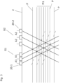
- FIG. 3 outlines a network of crossing points, which is spanned by a first group G1 of connected first ultrasonic transducers with three first ultrasonic transducers 20.1 and by a second group G2 of connected second ultrasonic transducers with three second ultrasonic transducers 20.2.
- the network would have the shape of a rhombus, with some crossing points being at the same distance from a wall of the measuring tube 2 . Due to different distances A1 and A2, the rhombus is distorted, i.e. a parallelogram, so that crossing points with otherwise the same distance to a measuring tube wall are now each arranged along a straight line inclined to the measuring tube wall, as indicated by the dashed lines.
- the distances between the parallels and the ultrasonic transducers depend on the distance between the first group and the second group. Pushing the second group closer to the first group results in a reduction in the distances between the parallels and the ultrasonic transducers. In this case, the arrangement could be used on measuring tubes with a small diameter.
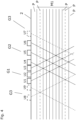
- the first group of first ultrasonic transducers G1 comprising the ultrasonic transducers U1 to U2 and the second group of ultrasonic transducers G2 comprising the ultrasonic transducers U4 to U6 clamp according to 3 a network of crossing points, with crossing points occupying a first set M1 of equidistant parallels P, and with crossing points occupying parallels P which do not belong to set M1.
- the gap between a parallel not belonging to set M1 and a parallel belonging to set M1 is one integer multiple of neighboring parallels of the set M1.
- the set M1 can be expanded by means of at least a third group of ultrasonic transducers G3, for example comprising the ultrasonic transducer U7 and/or the ultrasonic transducers U8 and U9, as shown by the parallel lines shown in dashed lines.
- the same can also be extended to ultrasonic transducer arrangements in which the first group of ultrasonic transducers and/or the second group of ultrasonic transducers have more than three ultrasonic transducers.
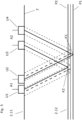
- FIG. 5 outlines ultrasonic signal paths depending on the measuring tube diameter. Ultrasonic signals, which are radiated into the measuring tube on a first side of the measuring tube 2.11, are reflected on a second side of the measuring tube 2.12 on an inside of the measuring tube wall.
- the ultrasonic signal paths of the ultrasonic transducers U2 and U4 are offset from one another, which results in a reduced ultrasonic signal amplitude in the receiving ultrasonic transducer. This is indicated by the thick dashed lines for an ultrasonic signal originating from U4.
- the inside of the second side of the measuring tube lies between the parallels P1 and P2 and is equidistant from both parallels, there is a maximum relevant deviation of the inside wall from one of the parallels P1 and P2. If the inner wall were closer to P1, the ultrasonic signal paths of ultrasonic transducers U2 and U4 would be more closely matched. If the inner wall were closer to P2, the ultrasonic signal paths of ultrasonic transducers U1 and U3 would be more closely matched. This is demonstrated by means of the thin dashed lines starting from U3 to U1 and starting from U4 to U2, which sketch an ultrasonic signal width neglecting a widening that occurs in practice. When reflected on the inner wall running exactly between P1 and P2, the Ultrasonic signals are no longer centered on the corresponding receiving ultrasonic transducer but offset, with the offset being the same for both ultrasonic signal paths.
- the arrangement has a third group G3 of ultrasonic transducers with a first ultrasonic transducer 20.1 and a second ultrasonic transducer 20.2, by means of which the most powerful set of equidistant parallels as in 4 is outlined.
- the ultrasonic transducer arrangement can have a third ultrasonic transducer 20.3, which is set up to emit ultrasonic signals perpendicular to the measuring tube axis and then receive them on the second side 2.12 after reflection on the inside of the measuring tube.
- a third ultrasonic transducer 20.3 which is set up to emit ultrasonic signals perpendicular to the measuring tube axis and then receive them on the second side 2.12 after reflection on the inside of the measuring tube.
- the carrier body can have positioning elements, by means of which the ultrasonic transducers can be positioned in a desired position during installation in the carrier body. After positioning, the ultrasonic transducers can be cast in the carrier body.
- the ultrasonic transducers can be held individually in the carrier body, for example, so that an adaptation to a rough or uneven measuring tube surface, for example, is possible. This sketch is to be interpreted as an example and not as a restriction with regard to the number and arrangement of the ultrasonic transducers.
- a clamp-on ultrasonic flowmeter does not have to have a curvature sensor.
- a curvature sensor has a distance sensor 4.1 and a spacer 4.2, which spacer has a central area 4.21 and two ends 4.22 angled from the central area. The spacer is placed on the measuring tube parallel to a measuring tube cross-section of the measuring tube 2, the central region having a distance from an outer surface of the measuring tube that depends on the outer diameter of the measuring tube. This distance is measured with the distance sensor 4.1 installed in the central area.
- a sensor can be an ultrasonic sensor or an optical sensor, for example.
- W-shaped signal paths with two reflections on the second side of the measuring tube and an intermediate reflection on the first side of the measuring tube 2.11 can also be selected. This can be advantageous in the case of small measuring tube diameters or when measuring tube vibrations caused by ultrasonic signal coupling are temporally superimposed upon arrival at an ultrasonic transducer intended for reception with ultrasonic signals which run along a V-shaped ultrasonic signal path.
- a pair of ultrasonic transducers comprising a first ultrasonic transducer and a second ultrasonic transducer.
- a measuring tube inner diameter and a measuring tube wall thickness can be determined by means of a third ultrasonic transducer, and a pair of ultrasonic transducers can thereby be determined.
- a curvature sensor can also be used as an alternative or in addition.
- a plurality of first and/or second ultrasonic transducers can emit ultrasonic signals at the same time or at different times.
- a selection of an ultrasonic transducer pair can then be determined, for example, based on an ultrasonic signal amplitude, which is measured by means of ultrasonic transducers intended for reception.
- different ultrasonic transducers used to emit ultrasonic signals can each impress one or more features on the ultrasonic signals.
- a center frequency be characteristic.
- ultrasonic signals can have different signal chirps.
- a medium can also be fed through the measuring tube and a transit time difference measurement of ultrasonic signals can be carried out.
- Ultrasonic signals with no transit time difference or with a transit time difference that is too small can be excluded from consideration.
- Such signals are, for example, signals which are coupled into the measuring tube from an original ultrasonic signal without passing through the medium.
- a receiving ultrasonic transducer starting from an original ultrasonic signal, a plurality of ultrasonic signals caused by different reflections can therefore arrive in a temporally superimposed or temporally offset manner.
Landscapes
- Physics & Mathematics (AREA)
- Electromagnetism (AREA)
- Fluid Mechanics (AREA)
- General Physics & Mathematics (AREA)
- Measuring Volume Flow (AREA)
Claims (9)
- Agencement de transducteurs à ultrasons (10) d'un point de mesure de débit à ultrasons clamp-on (1) basé sur le principe de la différence de temps de transit, lequel agencement comprend :plusieurs transducteurs à ultrasons (20), lesquels sont conçus pour être disposés sur un côté extérieur d'un tube de mesure (2) du point de mesure de débit clamp-on,les transducteurs à ultrasons (20) présentant chacun au moins un élément transducteur (21) destiné à générer et/ou à recevoir des signaux ultrasonores ainsi qu'un élément de couplage (22), l'élément de couplage présentant une première surface de contact (22.1) et une deuxième surface de contact (22.2), l'élément transducteur étant disposé sur la première surface de contact, et le transducteur à ultrasons étant conçu pour être mis en contact avec le tube de mesure au moyen de la deuxième surface de contact,les transducteurs à ultrasons étant conçus pour émettre des signaux ultrasonores dans le tube de mesure et/ou pour recevoir des signaux ultrasonores sortant du tube de mesure,les deuxièmes surfaces de contact présentant chacune une normale (N), les normales définissant un plan dans lequel s'étendent des chemins des signaux ultrasonores,des premiers transducteurs ultrasonores (20.1) définissant des premiers chemins de signaux ultrasonores (UP1) parallèles entre eux, et des deuxièmes transducteurs ultrasonores (20.2) définissant des deuxièmes chemins de signaux ultrasonores (UP2) parallèles entre eux, les chemins de signaux ultrasonores s'étendant dans le plan,les trajets de signaux ultrasonores des premiers transducteurs à ultrasons ainsi que des deuxièmes transducteurs à ultrasons dans l'élément de couplage s'étendant respectivement de manière oblique par rapport à la deuxième surface de contact,une direction des premiers trajets de signaux ultrasonores et une direction des deuxièmes trajets de signaux ultrasonores étant symétriques par rapport à l'une des normales,les premiers trajets de signaux ultrasonores présentant des points d'intersection (KP) dans le plan avec les deuxièmes trajets de signaux ultrasonores, les points d'intersection occupant des parallèles (P), lesquelles parallèles sont perpendiculaires aux normales dans le plan,un premier groupe (G1) de transducteurs à ultrasons contigus comprenant exclusivement des premiers transducteurs à ultrasons avec un premier nombre (Anz1), et un deuxième groupe (G2) de transducteurs à ultrasons contigus comprenant exclusivement des deuxièmes transducteurs à ultrasons avec un deuxième nombre (Anz2),des transducteurs à ultrasons voisins du premier groupe présentant dans la direction des parallèles respectivement des premières distances (A1) entre eux, et des transducteurs à ultrasons voisins du deuxième groupe présentant dans la direction des parallèles respectivement des deuxièmes distances (A2) entre eux, la première distance et la deuxième distance étant inégales,caractérisé en ce que2*A1 >= A2 >= 1,125*A1, et notamment 1,75*A1 >= A2 >= 1,16*A1, et de préférence 1,6*A1 >= A2 >= 1,25*A1,où une relation entre la première distance (A1) et la deuxième distance (A2) correspond à l'équation suivante :
(a+1)*A1=a*A2 avec b > a > 1, a étant un nombre naturel et b inférieur à 9, et notamment inférieur à 7, et de préférence inférieur à 5. - Agencement de transducteurs à ultrasons selon la revendication 1,pour lequel les éléments de couplage présentent chacun un axe longitudinal (L), l'axe longitudinal présentant respectivement un angle intérieur (α) par rapport à la deuxième surface de contact correspondante, le trajet du signal ultrasonore dans l'élément de couplage s'étendant le long de l'axe longitudinal,les éléments transducteurs présentant une extension radiale (rA), où
 et notamment
- Agencement de transducteurs à ultrasons selon la revendication 1 ou 2,pour lequel l'agencement de transducteurs à ultrasons présente au moins un troisième groupe (G3) de transducteurs à ultrasons avec au moins un premier transducteur à ultrasons et/ou au moins un deuxième transducteur à ultrasons,au moins un point d'intersection formé avec un premier transducteur à ultrasons du troisième groupe et/ou avec un deuxième transducteur à ultrasons du troisième groupe élargissant un premier ensemble (M1) le plus important de parallèles équidistantes.
- Agencement de transducteurs à ultrasons selon l'une des revendications précédentes,
comprenant au moins un troisième transducteur à ultrasons (20.3), lequel présente un trajet de signal qui est perpendiculaire à la deuxième surface de contact. - Agencement de transducteurs à ultrasons selon l'une des revendications précédentes,
pour lequel l'agencement est supporté par un corps de support (30), lequel corps de support est conçu pour positionner et supporter les transducteurs à ultrasons. - Agencement de transducteurs à ultrasons selon la revendication 5,
pour lequel les transducteurs à ultrasons sont maintenus individuellement dans le corps de support. - Point de mesure de débit à ultrasons clamp-on (1) destiné à mesurer une vitesse de débit d'un produit s'écoulant à travers un tube de mesure (2), lequel point de mesure comprend :le tube de mesure (2) destiné à guider un produit avec un axe de tube de mesure (2.1),un agencement de transducteurs à ultrasons (10) selon l'une des revendications précédentes, l'agencement de transducteurs à ultrasons étant orientée parallèlement à l'axe du tube de mesure,un circuit électronique de mesure/d'exploitation (3) destiné à faire fonctionner les transducteurs à ultrasons ainsi que pour déterminer et mettre à disposition des valeurs mesurées de la vitesse d'écoulement.
- Point de mesure de débit à ultrasons clamp-on selon la revendication 7,comprenant un capteur de courbure (4) destiné à déterminer un diamètre extérieur du tube de mesure,le capteur de courbure présentant un capteur de distance (4.1) et une entretoise (4.2),l'entretoise présentant une zone centrale (4.21) et deux extrémités (4.22) se raccordant à la zone centrale, les extrémités étant délimitées par une courbure ou un coude ou un angle par rapport à la zone centrale,l'entretoise étant conçue pour être mise en contact avec le tube de mesure au moyen des extrémités, la zone centrale étant conçue pour être espacée du tube de mesure, et une section transversale ou longitudinale de l'entretoise à travers les deux extrémités étant conçue pour être parallèle à une section transversale du tube de mesure,le capteur de distance étant disposé dans la zone centrale sur l'entretoise,le circuit électronique de mesure/d'exploitation (3) étant conçu pour faire fonctionner le capteur de distance.
- Point de mesure de débit à ultrasons clamp-on selon la revendication 8,
le capteur de distance étant un capteur de distance optique ou acoustique.
Applications Claiming Priority (2)
| Application Number | Priority Date | Filing Date | Title |
|---|---|---|---|
| DE102018132053.1A DE102018132053B4 (de) | 2018-12-13 | 2018-12-13 | Ultraschallwandleranordnung einer Clamp-On-Ultraschall-Durchflussmessstelle, und eine Clamp-On-Ultraschall-Durchflussmessstelle sowie Verfahren zur Inbetriebnahme der Clamp-On-Ultraschall-Durchflussmessstelle |
| PCT/EP2019/082015 WO2020120091A1 (fr) | 2018-12-13 | 2019-11-21 | Ensemble de transducteurs ultrasonores d'un point de mesure de débit à ultrasons du type "clamp-on", ainsi que point de mesure de débit à ultrasons du type "clamp-on" et procédé de mise en service dudit point de mesure de débit à ultrasons du type "clamp-on" |
Publications (2)
| Publication Number | Publication Date |
|---|---|
| EP3894800A1 EP3894800A1 (fr) | 2021-10-20 |
| EP3894800B1 true EP3894800B1 (fr) | 2023-08-09 |
Family
ID=68654480
Family Applications (1)
| Application Number | Title | Priority Date | Filing Date |
|---|---|---|---|
| EP19808759.5A Active EP3894800B1 (fr) | 2018-12-13 | 2019-11-21 | Ensemble de transducteurs ultrasonores d'un point de mesure de débit à ultrasons du type "clamp-on", ainsi que point de mesure de débit à ultrasons du type "clamp-on" et procédé de mise en service dudit point de mesure de débit à ultrasons du type "clamp-on" |
Country Status (5)
| Country | Link |
|---|---|
| US (1) | US11835372B2 (fr) |
| EP (1) | EP3894800B1 (fr) |
| CN (1) | CN113167619B (fr) |
| DE (1) | DE102018132053B4 (fr) |
| WO (1) | WO2020120091A1 (fr) |
Families Citing this family (6)
| Publication number | Priority date | Publication date | Assignee | Title |
|---|---|---|---|---|
| DE102018133476B4 (de) * | 2018-12-21 | 2023-11-02 | Endress+Hauser Flowtec Ag | Verfahren zur Inbetriebnahme und/oder Überprüfung einer Clamp-On Ultraschall-Durchflussmessstelle |
| DE102021115546A1 (de) * | 2021-06-16 | 2022-12-22 | Endress+Hauser Flowtec Ag | Anordnung von Ultraschallwandlern, Clamp-On-Ultraschall- Messgerät mit einer solchen Anordnung und Verfahren zum Einstellen des Ultraschallmessgeräts |
| US11971476B2 (en) * | 2021-06-30 | 2024-04-30 | Texas Instruments Incorporated | Ultrasonic equalization and gain control for smart speakers |
| CN116952317A (zh) * | 2023-08-07 | 2023-10-27 | 青岛鼎信通讯科技有限公司 | 一种应用于超声水表的四声路换能器 |
| CN117347948B (zh) * | 2023-10-08 | 2024-07-26 | 深圳市南科物联科技有限公司 | 基于一维和二维无线混合的区域边缘精准定位系统及方法 |
| JP7702178B2 (ja) * | 2023-11-07 | 2025-07-03 | 株式会社Qdot | 矩形管部用超音波流量測定装置 |
Family Cites Families (13)
| Publication number | Priority date | Publication date | Assignee | Title |
|---|---|---|---|---|
| EP0397596B1 (fr) * | 1989-05-09 | 1993-01-27 | Endress + Hauser Flowtec AG | Débitmètre supersonique |
| WO1995017650A1 (fr) * | 1993-12-23 | 1995-06-29 | Endress + Hauser Flowtec Ag | Appareil verrouillable de mesure par ultrasons du debit volumique |
| EP1173733B1 (fr) * | 1999-04-01 | 2011-05-18 | Panametrics, Inc. | Debitmetre aux ultrasons a pince pour fluides a faible densite |
| CN1278096C (zh) * | 2002-03-13 | 2006-10-04 | 博里利斯技术公司 | 用于检查管道形变的设备 |
| DE10258997A1 (de) * | 2002-12-16 | 2004-06-24 | Endress + Hauser Flowtec Ag, Reinach | Vorrichtung zur Postionierung eines Clamp-On Durchflußmeßgeräts an einem Behältnis |
| DE102004053673A1 (de) * | 2004-11-03 | 2006-05-04 | Endress + Hauser Flowtec Ag | Vorrichtung zur Bestimmung und/oder Überwachung des Volumen- und/oder Massendurchflusses eines Mediums |
| GB0620944D0 (en) * | 2006-10-20 | 2006-11-29 | Insensys Ltd | Curvature measurement moving relative to pipe |
| DE102008002166A1 (de) * | 2008-06-03 | 2009-12-10 | Endress + Hauser Flowtec Ag | Messsystem zur Bestimmung und/oder Überwachung des Durchflusses eines Messmediums durch ein Messrohr |
| DE102008029772A1 (de) * | 2008-06-25 | 2009-12-31 | Endress + Hauser Flowtec Ag | Verfahren und Messsystem zur Bestimmung und/oder Überwachung des Durchflusses eines Messmediums durch ein Messrohr |
| DE102011015677A1 (de) * | 2011-03-31 | 2012-10-04 | Rosen Swiss Ag | Akustischer Durchflussmesser |
| JP5985311B2 (ja) * | 2012-08-30 | 2016-09-06 | Ntn株式会社 | 軸受トラック溝測定装置および軸受トラック溝測定方法 |
| FR3003646B1 (fr) * | 2013-03-21 | 2015-04-03 | V & M France | Dispositif et procede de controle non destructif de produits tubulaires, notamment sur site |
| GB2521661A (en) * | 2013-12-27 | 2015-07-01 | Xsens As | Apparatus and method for measuring flow |
-
2018
- 2018-12-13 DE DE102018132053.1A patent/DE102018132053B4/de not_active Expired - Fee Related
-
2019
- 2019-11-21 WO PCT/EP2019/082015 patent/WO2020120091A1/fr not_active Ceased
- 2019-11-21 EP EP19808759.5A patent/EP3894800B1/fr active Active
- 2019-11-21 US US17/413,266 patent/US11835372B2/en active Active
- 2019-11-21 CN CN201980081321.XA patent/CN113167619B/zh active Active
Also Published As
| Publication number | Publication date |
|---|---|
| US11835372B2 (en) | 2023-12-05 |
| WO2020120091A1 (fr) | 2020-06-18 |
| CN113167619A (zh) | 2021-07-23 |
| EP3894800A1 (fr) | 2021-10-20 |
| DE102018132053B4 (de) | 2022-08-25 |
| US20220049983A1 (en) | 2022-02-17 |
| DE102018132053A1 (de) | 2020-06-18 |
| CN113167619B (zh) | 2024-12-10 |
Similar Documents
| Publication | Publication Date | Title |
|---|---|---|
| EP3894800B1 (fr) | Ensemble de transducteurs ultrasonores d'un point de mesure de débit à ultrasons du type "clamp-on", ainsi que point de mesure de débit à ultrasons du type "clamp-on" et procédé de mise en service dudit point de mesure de débit à ultrasons du type "clamp-on" | |
| EP1936333B1 (fr) | Débitmètre à ultrasons | |
| EP2386835B1 (fr) | Mesure par ultrasons de la vitesse d'écoulement d'un fluide dans une conduite | |
| DE102016112295B4 (de) | Ultraschallmessvorrichtung und Verfahren zum Messen der Strömungsgeschwindigkeit eines Fluids | |
| EP1554549A1 (fr) | Debitmetre | |
| DE2107586A1 (de) | Ultraschall Durchflußmesser | |
| DE102017110308A1 (de) | Ultraschalldurchflussmessgerät | |
| EP0566859B1 (fr) | Débitmètre ultrasonique avec canal de mesure hélicoidal | |
| EP3894799B1 (fr) | Agencement de transducteurs ultrasonores d'un appareil de mesure de debit a ultrasons a pinces, et appareil de mesure de debit a ultrasons a pinces et procede de mise en marche de l'appareil de mesure de debit a ultrasons a pinces | |
| EP3855134B1 (fr) | Dispositif de mesure du débit d'écoulement d'un fluide | |
| EP2072972A1 (fr) | Dispositif de mesure du mouvement d'un fluide dans un tuyau | |
| EP4182703B1 (fr) | Débitmètre et procédé de mesure du débit d'un fluide | |
| EP1931948B1 (fr) | Dispositif pour determiner ou controler le debit volumetrique ou massique d'un fluide dans une conduite | |
| DE102018110495B4 (de) | Coriolis-Messaufnehmer mit einer messrohrtorsionskompensierenden Sensorgruppe und ein Coriolis-Messgerät mit einem solchen Messaufnehmer | |
| EP3521774A1 (fr) | Dispositif de mesure d'écoulement à ultrasons et procédé de détermination de la vitesse d'écoulement | |
| EP3599446A1 (fr) | Compteur à ultrasons | |
| EP0080640B1 (fr) | Procédé et appareil pour détecter des bulles dans une fluide | |
| EP3748309B1 (fr) | Débitmètre à ultrasons, utilisation d'un débitmètre à ultrasons dans un organe d'arrêt et organe d'arrêt | |
| DE102020126021A1 (de) | Fluidmesseinrichtung | |
| DE102006047526A1 (de) | Strömungsgleichrichter | |
| EP2511673A1 (fr) | Procédé de mesure de la quantité de débit selon le principe de la différence du temps de parcours des ultrasons | |
| EP3268954B1 (fr) | Dispositif et appareil de terrain de la technique de mesure de processus | |
| DE10235033A1 (de) | Durchflußmesser | |
| EP4047328A1 (fr) | Débitmètre à ultrasons et procédé de détermination de la vitesse d'un milieu en écoulement | |
| DE102013005810A1 (de) | Verfahren zum Betrieb einer Ultraschallmessanordnung sowie Ultraschallmessanordnung |
Legal Events
| Date | Code | Title | Description |
|---|---|---|---|
| STAA | Information on the status of an ep patent application or granted ep patent |
Free format text: STATUS: UNKNOWN |
|
| STAA | Information on the status of an ep patent application or granted ep patent |
Free format text: STATUS: THE INTERNATIONAL PUBLICATION HAS BEEN MADE |
|
| PUAI | Public reference made under article 153(3) epc to a published international application that has entered the european phase |
Free format text: ORIGINAL CODE: 0009012 |
|
| STAA | Information on the status of an ep patent application or granted ep patent |
Free format text: STATUS: REQUEST FOR EXAMINATION WAS MADE |
|
| 17P | Request for examination filed |
Effective date: 20210507 |
|
| AK | Designated contracting states |
Kind code of ref document: A1 Designated state(s): AL AT BE BG CH CY CZ DE DK EE ES FI FR GB GR HR HU IE IS IT LI LT LU LV MC MK MT NL NO PL PT RO RS SE SI SK SM TR |
|
| DAV | Request for validation of the european patent (deleted) | ||
| DAX | Request for extension of the european patent (deleted) | ||
| REG | Reference to a national code |
Ref country code: DE Ipc: G01F0001667000 Ref country code: DE Ref legal event code: R079 Ref document number: 502019008909 Country of ref document: DE Free format text: PREVIOUS MAIN CLASS: G01F0001660000 Ipc: G01F0001667000 |
|
| GRAP | Despatch of communication of intention to grant a patent |
Free format text: ORIGINAL CODE: EPIDOSNIGR1 |
|
| STAA | Information on the status of an ep patent application or granted ep patent |
Free format text: STATUS: GRANT OF PATENT IS INTENDED |
|
| RIC1 | Information provided on ipc code assigned before grant |
Ipc: G01F 1/667 20220101AFI20230221BHEP |
|
| INTG | Intention to grant announced |
Effective date: 20230322 |
|
| GRAS | Grant fee paid |
Free format text: ORIGINAL CODE: EPIDOSNIGR3 |
|
| GRAA | (expected) grant |
Free format text: ORIGINAL CODE: 0009210 |
|
| STAA | Information on the status of an ep patent application or granted ep patent |
Free format text: STATUS: THE PATENT HAS BEEN GRANTED |
|
| AK | Designated contracting states |
Kind code of ref document: B1 Designated state(s): AL AT BE BG CH CY CZ DE DK EE ES FI FR GB GR HR HU IE IS IT LI LT LU LV MC MK MT NL NO PL PT RO RS SE SI SK SM TR |
|
| REG | Reference to a national code |
Ref country code: GB Ref legal event code: FG4D Free format text: NOT ENGLISH |
|
| REG | Reference to a national code |
Ref country code: CH Ref legal event code: EP |
|
| REG | Reference to a national code |
Ref country code: DE Ref legal event code: R096 Ref document number: 502019008909 Country of ref document: DE |
|
| REG | Reference to a national code |
Ref country code: IE Ref legal event code: FG4D Free format text: LANGUAGE OF EP DOCUMENT: GERMAN |
|
| REG | Reference to a national code |
Ref country code: NL Ref legal event code: FP |
|
| REG | Reference to a national code |
Ref country code: LT Ref legal event code: MG9D |
|
| P01 | Opt-out of the competence of the unified patent court (upc) registered |
Effective date: 20231027 |
|
| PG25 | Lapsed in a contracting state [announced via postgrant information from national office to epo] |
Ref country code: GR Free format text: LAPSE BECAUSE OF FAILURE TO SUBMIT A TRANSLATION OF THE DESCRIPTION OR TO PAY THE FEE WITHIN THE PRESCRIBED TIME-LIMIT Effective date: 20231110 |
|
| PG25 | Lapsed in a contracting state [announced via postgrant information from national office to epo] |
Ref country code: IS Free format text: LAPSE BECAUSE OF FAILURE TO SUBMIT A TRANSLATION OF THE DESCRIPTION OR TO PAY THE FEE WITHIN THE PRESCRIBED TIME-LIMIT Effective date: 20231209 |
|
| PG25 | Lapsed in a contracting state [announced via postgrant information from national office to epo] |
Ref country code: SE Free format text: LAPSE BECAUSE OF FAILURE TO SUBMIT A TRANSLATION OF THE DESCRIPTION OR TO PAY THE FEE WITHIN THE PRESCRIBED TIME-LIMIT Effective date: 20230809 Ref country code: RS Free format text: LAPSE BECAUSE OF FAILURE TO SUBMIT A TRANSLATION OF THE DESCRIPTION OR TO PAY THE FEE WITHIN THE PRESCRIBED TIME-LIMIT Effective date: 20230809 Ref country code: PT Free format text: LAPSE BECAUSE OF FAILURE TO SUBMIT A TRANSLATION OF THE DESCRIPTION OR TO PAY THE FEE WITHIN THE PRESCRIBED TIME-LIMIT Effective date: 20231211 Ref country code: NO Free format text: LAPSE BECAUSE OF FAILURE TO SUBMIT A TRANSLATION OF THE DESCRIPTION OR TO PAY THE FEE WITHIN THE PRESCRIBED TIME-LIMIT Effective date: 20231109 Ref country code: LV Free format text: LAPSE BECAUSE OF FAILURE TO SUBMIT A TRANSLATION OF THE DESCRIPTION OR TO PAY THE FEE WITHIN THE PRESCRIBED TIME-LIMIT Effective date: 20230809 Ref country code: LT Free format text: LAPSE BECAUSE OF FAILURE TO SUBMIT A TRANSLATION OF THE DESCRIPTION OR TO PAY THE FEE WITHIN THE PRESCRIBED TIME-LIMIT Effective date: 20230809 Ref country code: IS Free format text: LAPSE BECAUSE OF FAILURE TO SUBMIT A TRANSLATION OF THE DESCRIPTION OR TO PAY THE FEE WITHIN THE PRESCRIBED TIME-LIMIT Effective date: 20231209 Ref country code: HR Free format text: LAPSE BECAUSE OF FAILURE TO SUBMIT A TRANSLATION OF THE DESCRIPTION OR TO PAY THE FEE WITHIN THE PRESCRIBED TIME-LIMIT Effective date: 20230809 Ref country code: GR Free format text: LAPSE BECAUSE OF FAILURE TO SUBMIT A TRANSLATION OF THE DESCRIPTION OR TO PAY THE FEE WITHIN THE PRESCRIBED TIME-LIMIT Effective date: 20231110 Ref country code: FI Free format text: LAPSE BECAUSE OF FAILURE TO SUBMIT A TRANSLATION OF THE DESCRIPTION OR TO PAY THE FEE WITHIN THE PRESCRIBED TIME-LIMIT Effective date: 20230809 |
|
| PG25 | Lapsed in a contracting state [announced via postgrant information from national office to epo] |
Ref country code: PL Free format text: LAPSE BECAUSE OF FAILURE TO SUBMIT A TRANSLATION OF THE DESCRIPTION OR TO PAY THE FEE WITHIN THE PRESCRIBED TIME-LIMIT Effective date: 20230809 |
|
| PG25 | Lapsed in a contracting state [announced via postgrant information from national office to epo] |
Ref country code: ES Free format text: LAPSE BECAUSE OF FAILURE TO SUBMIT A TRANSLATION OF THE DESCRIPTION OR TO PAY THE FEE WITHIN THE PRESCRIBED TIME-LIMIT Effective date: 20230809 |
|
| PG25 | Lapsed in a contracting state [announced via postgrant information from national office to epo] |
Ref country code: SM Free format text: LAPSE BECAUSE OF FAILURE TO SUBMIT A TRANSLATION OF THE DESCRIPTION OR TO PAY THE FEE WITHIN THE PRESCRIBED TIME-LIMIT Effective date: 20230809 Ref country code: RO Free format text: LAPSE BECAUSE OF FAILURE TO SUBMIT A TRANSLATION OF THE DESCRIPTION OR TO PAY THE FEE WITHIN THE PRESCRIBED TIME-LIMIT Effective date: 20230809 Ref country code: ES Free format text: LAPSE BECAUSE OF FAILURE TO SUBMIT A TRANSLATION OF THE DESCRIPTION OR TO PAY THE FEE WITHIN THE PRESCRIBED TIME-LIMIT Effective date: 20230809 Ref country code: EE Free format text: LAPSE BECAUSE OF FAILURE TO SUBMIT A TRANSLATION OF THE DESCRIPTION OR TO PAY THE FEE WITHIN THE PRESCRIBED TIME-LIMIT Effective date: 20230809 Ref country code: DK Free format text: LAPSE BECAUSE OF FAILURE TO SUBMIT A TRANSLATION OF THE DESCRIPTION OR TO PAY THE FEE WITHIN THE PRESCRIBED TIME-LIMIT Effective date: 20230809 Ref country code: SK Free format text: LAPSE BECAUSE OF FAILURE TO SUBMIT A TRANSLATION OF THE DESCRIPTION OR TO PAY THE FEE WITHIN THE PRESCRIBED TIME-LIMIT Effective date: 20230809 |
|
| REG | Reference to a national code |
Ref country code: DE Ref legal event code: R097 Ref document number: 502019008909 Country of ref document: DE |
|
| PG25 | Lapsed in a contracting state [announced via postgrant information from national office to epo] |
Ref country code: IT Free format text: LAPSE BECAUSE OF FAILURE TO SUBMIT A TRANSLATION OF THE DESCRIPTION OR TO PAY THE FEE WITHIN THE PRESCRIBED TIME-LIMIT Effective date: 20230809 |
|
| PLBE | No opposition filed within time limit |
Free format text: ORIGINAL CODE: 0009261 |
|
| STAA | Information on the status of an ep patent application or granted ep patent |
Free format text: STATUS: NO OPPOSITION FILED WITHIN TIME LIMIT |
|
| REG | Reference to a national code |
Ref country code: CH Ref legal event code: PL |
|
| PG25 | Lapsed in a contracting state [announced via postgrant information from national office to epo] |
Ref country code: MC Free format text: LAPSE BECAUSE OF FAILURE TO SUBMIT A TRANSLATION OF THE DESCRIPTION OR TO PAY THE FEE WITHIN THE PRESCRIBED TIME-LIMIT Effective date: 20230809 |
|
| PG25 | Lapsed in a contracting state [announced via postgrant information from national office to epo] |
Ref country code: LU Free format text: LAPSE BECAUSE OF NON-PAYMENT OF DUE FEES Effective date: 20231121 |
|
| 26N | No opposition filed |
Effective date: 20240513 |
|
| PG25 | Lapsed in a contracting state [announced via postgrant information from national office to epo] |
Ref country code: CH Free format text: LAPSE BECAUSE OF NON-PAYMENT OF DUE FEES Effective date: 20231130 |
|
| PG25 | Lapsed in a contracting state [announced via postgrant information from national office to epo] |
Ref country code: MC Free format text: LAPSE BECAUSE OF FAILURE TO SUBMIT A TRANSLATION OF THE DESCRIPTION OR TO PAY THE FEE WITHIN THE PRESCRIBED TIME-LIMIT Effective date: 20230809 Ref country code: CH Free format text: LAPSE BECAUSE OF NON-PAYMENT OF DUE FEES Effective date: 20231130 Ref country code: LU Free format text: LAPSE BECAUSE OF NON-PAYMENT OF DUE FEES Effective date: 20231121 Ref country code: SI Free format text: LAPSE BECAUSE OF FAILURE TO SUBMIT A TRANSLATION OF THE DESCRIPTION OR TO PAY THE FEE WITHIN THE PRESCRIBED TIME-LIMIT Effective date: 20230809 |
|
| REG | Reference to a national code |
Ref country code: BE Ref legal event code: MM Effective date: 20231130 |
|
| REG | Reference to a national code |
Ref country code: IE Ref legal event code: MM4A |
|
| PG25 | Lapsed in a contracting state [announced via postgrant information from national office to epo] |
Ref country code: IE Free format text: LAPSE BECAUSE OF NON-PAYMENT OF DUE FEES Effective date: 20231121 |
|
| PG25 | Lapsed in a contracting state [announced via postgrant information from national office to epo] |
Ref country code: BE Free format text: LAPSE BECAUSE OF NON-PAYMENT OF DUE FEES Effective date: 20231130 |
|
| PG25 | Lapsed in a contracting state [announced via postgrant information from national office to epo] |
Ref country code: IE Free format text: LAPSE BECAUSE OF NON-PAYMENT OF DUE FEES Effective date: 20231121 Ref country code: BE Free format text: LAPSE BECAUSE OF NON-PAYMENT OF DUE FEES Effective date: 20231130 |
|
| PG25 | Lapsed in a contracting state [announced via postgrant information from national office to epo] |
Ref country code: BG Free format text: LAPSE BECAUSE OF FAILURE TO SUBMIT A TRANSLATION OF THE DESCRIPTION OR TO PAY THE FEE WITHIN THE PRESCRIBED TIME-LIMIT Effective date: 20230809 |
|
| PG25 | Lapsed in a contracting state [announced via postgrant information from national office to epo] |
Ref country code: BG Free format text: LAPSE BECAUSE OF FAILURE TO SUBMIT A TRANSLATION OF THE DESCRIPTION OR TO PAY THE FEE WITHIN THE PRESCRIBED TIME-LIMIT Effective date: 20230809 |
|
| PG25 | Lapsed in a contracting state [announced via postgrant information from national office to epo] |
Ref country code: CY Free format text: LAPSE BECAUSE OF FAILURE TO SUBMIT A TRANSLATION OF THE DESCRIPTION OR TO PAY THE FEE WITHIN THE PRESCRIBED TIME-LIMIT; INVALID AB INITIO Effective date: 20191121 |
|
| PG25 | Lapsed in a contracting state [announced via postgrant information from national office to epo] |
Ref country code: HU Free format text: LAPSE BECAUSE OF FAILURE TO SUBMIT A TRANSLATION OF THE DESCRIPTION OR TO PAY THE FEE WITHIN THE PRESCRIBED TIME-LIMIT; INVALID AB INITIO Effective date: 20191121 |
|
| PG25 | Lapsed in a contracting state [announced via postgrant information from national office to epo] |
Ref country code: TR Free format text: LAPSE BECAUSE OF FAILURE TO SUBMIT A TRANSLATION OF THE DESCRIPTION OR TO PAY THE FEE WITHIN THE PRESCRIBED TIME-LIMIT Effective date: 20230809 |
|
| PGFP | Annual fee paid to national office [announced via postgrant information from national office to epo] |
Ref country code: NL Payment date: 20251119 Year of fee payment: 7 |
|
| PGFP | Annual fee paid to national office [announced via postgrant information from national office to epo] |
Ref country code: DE Payment date: 20251119 Year of fee payment: 7 |
|
| PGFP | Annual fee paid to national office [announced via postgrant information from national office to epo] |
Ref country code: GB Payment date: 20251121 Year of fee payment: 7 |
|
| PG25 | Lapsed in a contracting state [announced via postgrant information from national office to epo] |
Ref country code: AT Free format text: LAPSE BECAUSE OF NON-PAYMENT OF DUE FEES Effective date: 20241121 |
|
| PGFP | Annual fee paid to national office [announced via postgrant information from national office to epo] |
Ref country code: FR Payment date: 20251126 Year of fee payment: 7 |
|
| REG | Reference to a national code |
Ref country code: AT Ref legal event code: MM01 Ref document number: 1598020 Country of ref document: AT Kind code of ref document: T Effective date: 20241121 |
|
| PGFP | Annual fee paid to national office [announced via postgrant information from national office to epo] |
Ref country code: CZ Payment date: 20251113 Year of fee payment: 7 |
|
| PGFP | Annual fee paid to national office [announced via postgrant information from national office to epo] |
Ref country code: AT Payment date: 20260410 Year of fee payment: 5 |