EP3895258B1 - Ensemble bague collectrice - Google Patents
Ensemble bague collectrice Download PDFInfo
- Publication number
- EP3895258B1 EP3895258B1 EP19897368.7A EP19897368A EP3895258B1 EP 3895258 B1 EP3895258 B1 EP 3895258B1 EP 19897368 A EP19897368 A EP 19897368A EP 3895258 B1 EP3895258 B1 EP 3895258B1
- Authority
- EP
- European Patent Office
- Prior art keywords
- conducting
- slip ring
- ring assembly
- disks
- finger
- Prior art date
- Legal status (The legal status is an assumption and is not a legal conclusion. Google has not performed a legal analysis and makes no representation as to the accuracy of the status listed.)
- Active
Links
Images

Classifications
-
- F—MECHANICAL ENGINEERING; LIGHTING; HEATING; WEAPONS; BLASTING
- F03—MACHINES OR ENGINES FOR LIQUIDS; WIND, SPRING, OR WEIGHT MOTORS; PRODUCING MECHANICAL POWER OR A REACTIVE PROPULSIVE THRUST, NOT OTHERWISE PROVIDED FOR
- F03D—WIND MOTORS
- F03D80/00—Details, components or accessories not provided for in groups F03D1/00 - F03D17/00
- F03D80/80—Arrangement of components within nacelles or towers
- F03D80/82—Arrangement of components within nacelles or towers of electrical components
- F03D80/85—Cabling
-
- H—ELECTRICITY
- H02—GENERATION; CONVERSION OR DISTRIBUTION OF ELECTRIC POWER
- H02K—DYNAMO-ELECTRIC MACHINES
- H02K13/00—Structural associations of current collectors with motors or generators, e.g. brush mounting plates or connections to windings; Disposition of current collectors in motors or generators; Arrangements for improving commutation
- H02K13/003—Structural associations of slip-rings
-
- F—MECHANICAL ENGINEERING; LIGHTING; HEATING; WEAPONS; BLASTING
- F03—MACHINES OR ENGINES FOR LIQUIDS; WIND, SPRING, OR WEIGHT MOTORS; PRODUCING MECHANICAL POWER OR A REACTIVE PROPULSIVE THRUST, NOT OTHERWISE PROVIDED FOR
- F03D—WIND MOTORS
- F03D80/00—Details, components or accessories not provided for in groups F03D1/00 - F03D17/00
-
- F—MECHANICAL ENGINEERING; LIGHTING; HEATING; WEAPONS; BLASTING
- F03—MACHINES OR ENGINES FOR LIQUIDS; WIND, SPRING, OR WEIGHT MOTORS; PRODUCING MECHANICAL POWER OR A REACTIVE PROPULSIVE THRUST, NOT OTHERWISE PROVIDED FOR
- F03D—WIND MOTORS
- F03D80/00—Details, components or accessories not provided for in groups F03D1/00 - F03D17/00
- F03D80/80—Arrangement of components within nacelles or towers
-
- H—ELECTRICITY
- H01—ELECTRIC ELEMENTS
- H01R—ELECTRICALLY-CONDUCTIVE CONNECTIONS; STRUCTURAL ASSOCIATIONS OF A PLURALITY OF MUTUALLY-INSULATED ELECTRICAL CONNECTING ELEMENTS; COUPLING DEVICES; CURRENT COLLECTORS
- H01R39/00—Rotary current collectors, distributors or interrupters
- H01R39/02—Details for dynamo electric machines
- H01R39/022—Details for dynamo electric machines characterised by the materials used, e.g. ceramics
- H01R39/025—Conductive materials
-
- H—ELECTRICITY
- H01—ELECTRIC ELEMENTS
- H01R—ELECTRICALLY-CONDUCTIVE CONNECTIONS; STRUCTURAL ASSOCIATIONS OF A PLURALITY OF MUTUALLY-INSULATED ELECTRICAL CONNECTING ELEMENTS; COUPLING DEVICES; CURRENT COLLECTORS
- H01R39/00—Rotary current collectors, distributors or interrupters
- H01R39/02—Details for dynamo electric machines
- H01R39/08—Slip-rings
- H01R39/10—Slip-rings other than with external cylindrical contact surface, e.g. flat slip-rings
-
- H—ELECTRICITY
- H01—ELECTRIC ELEMENTS
- H01R—ELECTRICALLY-CONDUCTIVE CONNECTIONS; STRUCTURAL ASSOCIATIONS OF A PLURALITY OF MUTUALLY-INSULATED ELECTRICAL CONNECTING ELEMENTS; COUPLING DEVICES; CURRENT COLLECTORS
- H01R39/00—Rotary current collectors, distributors or interrupters
- H01R39/02—Details for dynamo electric machines
- H01R39/14—Fastenings of commutators or slip-rings to shafts
-
- H—ELECTRICITY
- H01—ELECTRIC ELEMENTS
- H01R—ELECTRICALLY-CONDUCTIVE CONNECTIONS; STRUCTURAL ASSOCIATIONS OF A PLURALITY OF MUTUALLY-INSULATED ELECTRICAL CONNECTING ELEMENTS; COUPLING DEVICES; CURRENT COLLECTORS
- H01R39/00—Rotary current collectors, distributors or interrupters
- H01R39/02—Details for dynamo electric machines
- H01R39/18—Contacts for co-operation with commutator or slip-ring, e.g. contact brush
- H01R39/20—Contacts for co-operation with commutator or slip-ring, e.g. contact brush characterised by the material thereof
-
- H—ELECTRICITY
- H01—ELECTRIC ELEMENTS
- H01R—ELECTRICALLY-CONDUCTIVE CONNECTIONS; STRUCTURAL ASSOCIATIONS OF A PLURALITY OF MUTUALLY-INSULATED ELECTRICAL CONNECTING ELEMENTS; COUPLING DEVICES; CURRENT COLLECTORS
- H01R39/00—Rotary current collectors, distributors or interrupters
- H01R39/64—Devices for uninterrupted current collection
-
- H—ELECTRICITY
- H02—GENERATION; CONVERSION OR DISTRIBUTION OF ELECTRIC POWER
- H02K—DYNAMO-ELECTRIC MACHINES
- H02K7/00—Arrangements for handling mechanical energy structurally associated with dynamo-electric machines, e.g. structural association with mechanical driving motors or auxiliary dynamo-electric machines
- H02K7/18—Structural association of electric generators with mechanical driving motors, e.g. with turbines
- H02K7/1807—Rotary generators
- H02K7/1823—Rotary generators structurally associated with turbines or similar engines
- H02K7/183—Rotary generators structurally associated with turbines or similar engines wherein the turbine is a wind turbine
- H02K7/1838—Generators mounted in a nacelle or similar structure of a horizontal axis wind turbine
-
- F—MECHANICAL ENGINEERING; LIGHTING; HEATING; WEAPONS; BLASTING
- F05—INDEXING SCHEMES RELATING TO ENGINES OR PUMPS IN VARIOUS SUBCLASSES OF CLASSES F01-F04
- F05B—INDEXING SCHEME RELATING TO WIND, SPRING, WEIGHT, INERTIA OR LIKE MOTORS, TO MACHINES OR ENGINES FOR LIQUIDS COVERED BY SUBCLASSES F03B, F03D AND F03G
- F05B2220/00—Application
- F05B2220/70—Application in combination with
- F05B2220/706—Application in combination with an electrical generator
-
- H—ELECTRICITY
- H01—ELECTRIC ELEMENTS
- H01R—ELECTRICALLY-CONDUCTIVE CONNECTIONS; STRUCTURAL ASSOCIATIONS OF A PLURALITY OF MUTUALLY-INSULATED ELECTRICAL CONNECTING ELEMENTS; COUPLING DEVICES; CURRENT COLLECTORS
- H01R39/00—Rotary current collectors, distributors or interrupters
- H01R39/02—Details for dynamo electric machines
- H01R39/18—Contacts for co-operation with commutator or slip-ring, e.g. contact brush
- H01R39/26—Solid sliding contacts, e.g. carbon brush
-
- Y—GENERAL TAGGING OF NEW TECHNOLOGICAL DEVELOPMENTS; GENERAL TAGGING OF CROSS-SECTIONAL TECHNOLOGIES SPANNING OVER SEVERAL SECTIONS OF THE IPC; TECHNICAL SUBJECTS COVERED BY FORMER USPC CROSS-REFERENCE ART COLLECTIONS [XRACs] AND DIGESTS
- Y02—TECHNOLOGIES OR APPLICATIONS FOR MITIGATION OR ADAPTATION AGAINST CLIMATE CHANGE
- Y02E—REDUCTION OF GREENHOUSE GAS [GHG] EMISSIONS, RELATED TO ENERGY GENERATION, TRANSMISSION OR DISTRIBUTION
- Y02E10/00—Energy generation through renewable energy sources
- Y02E10/70—Wind energy
- Y02E10/72—Wind turbines with rotation axis in wind direction
Definitions
- the present invention generally relates to electrical arrangements in wind turbines, and more particularly relates to a slip ring assembly suitable for use in orientable wind turbines.
- Typical wind turbines are generally made of a pole having several tubular sections mounted together with a nacelle positioned at the top of the pole. Electrical cables and/or rigid aluminum/copper conductors attached to the tubular sections are typically used to convey the electric power produced by the generator from the nacelle to the bottom of the wind turbine.
- Horizontal axis wind turbines are usually provided with a yaw drive mounted in the nacelle and devised to orient the rotor with the blades to face the wind whichever is the direction of the wind.
- the yaw drive is operated to rotate the nacelle in an adequate direction so as to face the wind while the tubular sections remain fixed relative to the ground.
- the power produced by the generator in the nacelle must be transferred down the pole, for example for connection to the power system. Since the generator must yaw to keep pointed into the wind, the main power cables or conductors have to be adapted to handle this rotating movement.
- a flexible cable is attached in a loose loop from the wind generator power terminals to where the distribution conductors come up the pole.
- the cable is generally long enough for allowing several wraps of the flexible cable loop , thereby allowing the required movements of the nacelle during a convenient time without maintenance. However, maintenance is still required to unwind the cable when required.
- a lap counter associated to the electronic control system of the wind turbine may be used to monitor winding and unwinding of the cable loop. If there is too much winding in one direction, the control system may then rotate the wind turbine in the opposite direction in order to unwind the cable loop. Such solution complexifies the control of the wind turbine and increases the costs. Moreover, during the unwinding operation, the wind turbine may not be able to be used optimally for power generation.
- DE 699 08 011 T2 discloses a slip ring assembly according to the preamble of claim 1.
- the slip ring assembly further comprises a housing to be positioned so as to have a fixed position relative to the fixed pole, the conducting disks being positioned whiting the housing and being rotatable relative to the housing.
- the housing comprises a first wall provided with a connection aperture, a second wall opposite to the first wall and a lateral wall extending between the first and second walls, the second wall being securable to the fixed pole.
- each one of the plurality of slip rings comprises a conducting plate extending longitudinally between a first plate end and a second plate end and having the at least one upper conducting finger projecting from the first plate end and secured on a first face thereof and the at least one upper conducting finger projecting from the first plate end and secured on a second face thereof, the second face being opposite to the first face, and the second plate end being electrically connectable to a given one of the fixed electrical distribution conductors.
- the lateral wall is provided with a plurality of connection holes each for receiving the conducting plate of a respective one of the slip rings therein.
- the conducting discs are rotatably secured to the second wall of the housing.
- the slip ring assembly further comprises a plurality of elongated conductors each extending longitudinally between a first connection end electrically connectable to the generator and a second connection end electrically connected to a respective one of the conducting discs.
- each one of the elongated conductors extends within a tunnel formed by an inner aperture of the conducting discs up to the respective one of the conducting discs and through the connection aperture of the first wall of the housing.
- a diameter of the inner aperture is identical for all of the conducting disks.
- an inner edge of each one of the conducting discs is provided with a inwardly projecting mounting section, the second connection end elongated conductor being secured to the inwardly projecting mounting section.
- a diameter of the inner aperture varies from one of the conducting disks to another one of the conducting disks.
- the slip ring assembly further comprises a cover rotatably mounted to the housing and comprising a plurality of conductor holes each for receiving a respective one of the elongated conductors.
- the slip ring assembly further comprises a plurality of resilient devices each being mounted with a corresponding slip ring for urging the at least one upper conducting finger and the at least one lower conducting finger against the respective one of the conducting disks to maintain the electrical connection therebetween.
- the at least one upper conducting finger comprises a plurality of upper fingers mounted side-by-side and the at least one lower conducting finger comprises a plurality of lower fingers mounted side-by-side and each being associated with a respective one of the upper fingers to form a plurality of pairs of fingers.
- each one of the resilient devices comprises a plurality of springs each being associated with a respective one of the pairs of fingers.
- each one of the lower fingers and each one of the lower fingers are each provided with a rounded end for abutting the conducting plate.
- each one of the upper and lower conducting fingers is silver plated.
- each one of the conducting disks is provided with an outer upper silver plated surface and an outer lower silver plated surface.
- the present electrical connection arrangement is particularly devised to provide an efficient and/or safe electrical connection between electrical conductors provided on a fixed element/object and other electrical conductors provided on a rotating element/object, such as in a wind turbine provided with a yaw drive.
- the nacelle embedding the generator swivels and rotates according to the wind while the conductors used for conveying the generated power to the bottom of the wind turbine are typically fixedly secured along a conductor path along the pole of the wind turbine.
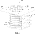
- slip ring assembly 100 for providing electrical connection between electrical output conductors of a generator of an orientable wind turbine (not shown) for example and fixed electrical distribution conductors (not shown), according to one embodiment.
- the slip ring assembly 100 is mounted inside a housing 102 that may be fixedly attached to the pole of the wind turbine (not shown).
- the housing 102 is made of electrically insulating material and comprises an upper wall 106 provided with an opening 104 for electrical connection purposes, a bottom wall 108 and a lateral wall having four panels/faces and extending between the upper and bottom walls 106 and 108. but various other arrangements may be considered, as it will become apparent below.
- the housing 102 comprises a bottom wall
- the slip ring assembly 100 may be adapted for use with any number of input electrical conductors and/or any number of output electrical conductors.
- the slip ring assembly 100 is devised to electrically connect seven input conductors each to a respective one of seven output conductors.
- the seven input conductors may comprise three input conductors for the rotor of a generator (1 per phase), three input conductors for the stator of the generator (1 per phase) and one input conductor for the ground.
- the seven output conductors also comprise three output conductors for the rotor, three output conductors for the stator and one output conductor for the ground.
- Other arrangements using one or two phases only with or without a neutral and/or a ground may also be considered for another exemplary application.
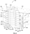
- the slip ring assembly 100 comprises seven spaced-apart rotating conducting disks 200 stacked mounted, i.e. the disks 200 share a same rotation axis and are positioned at different locations along the rotation axis.
- Each disk 200 is rotatably secured to the housing 102.
- the disks 200 have a fixed relative position so that a rotation of one of the disks 200 triggers the rotation of the other disks 200.
- Each disk 200 is made of an electrically conducting material.
- adjacent disks 200 are electrically insulated from one another. In this case, it should be understood that any adequate devices for electrically adjacent disks 200 may be used.
- disk electrical isolators 202 made from an electrically insulating material and distributed at various locations around the surface area of the conducting disks 200 are positioned between two adjacent conducting disks 200 to secure them together and electrically isolate them from each other.
- eight disk isolators 202 are used for electrically isolating two adjacent conducting disks 200.
- the eight disk isolators 202 are grouped as four sets of two disk isolators 202 and the two disk isolators 202 of a same set have the same angular position around the circumference of the conducting disks 200.
- the four sets of disk isolators 202 have a different respective angular position around the circumference of the conducting disks 200 and are evenly angularly spaced, i.e. the sets of disk isolators are positioned at 0, 90, 180 and 270 degrees around the circumference of the conducting disks 200. Furthermore, the four sets of disk isolators 202 connecting two given adjacent conducting disks 200 are each aligned with a respective one of four sets of disk isolators 202 connecting two other conducting disks 200.
- disk isolators 202 may vary.
- any adequate method and/or device for securing a disk isolator 202 to a conducting disk 200 may be used.
- a threaded rod or pin (not shown) may be mounted through a hole provided in the conducting disk 200 to secure a disk isolator 202 extending above and/or below the conducting disk 200 to the conducting disk 200 .
- the lowest disk 200 is fixedly secured to a mounting disk 230 which is rotatably secured to a bottom wall of the housing 102 so as to be rotatable about the rotation axis of the conducting disks 200. Since the conducting disks 200 are all secured together thanks to the disk isolators 202 and the lowest conducting disk 200 is secured to the rotating mounting disk 230, the rotation of any of the conducting disk 200 triggers the rotation of the assembly composed of all of the conducting disks 200 and the mounting disk 230. It should be understood that any adequate means for securing the lowest conducting disk 200 to the mounting disk 230 may be used and that any adequate means for rotatably securing the mounting the mounting disk 230 to the housing 202 may also be used.
- the lowest disk 200 is secured to the mounting disk 230 using disk isolators 202.
- the mounting disk 230 may be made of electrically conducting material. However, it should be understood that the mounting disk may be alternatively made from electrically isolating material.
- the mounting disk 230 is rotatably secured to the bottom of the housing 102 with brackets 232 restraining lateral movements of the mounting disk 230.
- the mounting disk 230 is adapted for sliding on corresponding sliding surfaces provided on the brackets 232 although other arrangements may be used.
- the mounting disk 230 and the brackets 232 are made of insulating material.
- the disk isolators 202 are made of a rubber material such as ethylene propylene diene monomer (EPDM) high creepage resistant material. According to this aspect of the invention, the disk isolators 202 are also used as a system damping device when used in applications where vibrations are important.
- EPDM ethylene propylene diene monomer
- the housing 102 is provided with an upper cover 240 mounted into the aperture 104 for completely enclosing the stacked disks 200.
- the upper cover 240 is made of insulating material and is rotatably mounted to the housing 102.
- the upper cover 240 is attached to the adjacent uppermost disk 200 through disks isolators 202, as detailed above.
- the aperture 104 is provided with a radial support flange 112 for rotatably supporting the upper cover 240 thereon but other arrangements may be considered.
- FIG. 5 shows an upper cover 240 according to one embodiment.
- the upper cover 240 has a disk-shaped plate 242 provided with 7 apertures 244 distributed therearound for receiving a respective electrical conductor therethrough, as it will become apparent below.
- Each aperture 244 has a circular hole 246 and a rectangular aperture 248 connected thereto, for easing the mounting and dismounting of the assembly 100, as it will become apparent below.
- the upper cover 240 is also provided with four circular arc shaped plates 250, 252, 254, 256 mounted with bolt and nut arrangements (not shown) to the disk-shaped plate 242 and distributed therearound for covering the rectangular apertures 248 once the conductors have been mounted therein, as detailed below.
- three of the circular arc shaped plates 250, 252, 254 have an inner edge 258 provided with two spaced apart arc shaped recesses 260, 262, each recess 260, 262 mating with a respective conductor.
- the fourth circular arc shaped plate 256 has an inner edge 264 provided with a single arc shaped recess 266 for mating with a respective conductor. Such embodiment may protect the interior of the housing 102 from the surrounding.
- each disk 200 is mechanically and electrically connectable to the generator using an electrical connection assembly for each disk 200.
- the electrical connection assembly comprises an elongated electrical conductors 210 for each conducting disk 200.
- Each elongated electrical conductor 210 extends longitudinally between a first end electrically connectable to a respective conducting disk 200 and a second end electrically connectable to the generator.
- the electrical connection assembly further comprises connection plates 216 each secured at the second end of a respective elongated electrical conductor 210, and each connection plate 216 is secured to a respective output of the generator.
- connection plate 216 is rectangular and welded to an elongated electrical conductor 216, it should be understood that the shape and size of the connection plate 216 may vary and any adequate method for securing the connection plate 216 to the elongated electrical conductor 210 may be used.
- the elongated electrical conductors 210 have a tubular shape in the illustrated embodiment, it should be understood that the shape of the elongated electrical conductors 210 may vary and could rectangular for example.
- each elongated electrical conductor 210 is provided with a slot in which a respective connection plate 216 is inserted, it should be understood that any other adequate means for securing a connection plate 216 to an elongated electrical conductor 210 may be used.
- connection plates 216 are omitted and the electrical outputs of the generator are each directly electrically connected to a respective elongated electrical conductor 210.
- the conducting disks 200 are identical, i.e. they have the same inner diameter, the same outer diameter and the same thickness.
- Each conducting disk 200 is provided with a concentric aperture 204 defining an inner edge 206 and a protrusion or mounting element 208 that projects inwardly from the edge 206.
- the conducting disks 200 are stacked one on top of the other so that their apertures 204 be aligned to form a tunnel or cavity in which the elongated electrical connectors 210 are inserted.
- the relative position of the conducting disks 200 is chosen so that the protrusions 208 are each at a different angular position and not vertically aligned. In one embodiment, the relative position of the conducting disks 200 is chosen so that the protrusions 208 are evenly angularly distributed about the circumference of stacked conducting disks 200.
- Each elongated electrical conductor 210 is positioned partially within the cavity formed by the concentric apertures 204 of the stacked conducting disks 200 so that its first end 214 be secured to the protrusion 208 of a respective conducting disk 200 and its second end be located outside of the housing 102.
- the length of the elongated electrical conductors 210 varies from one elongated electrical conductor 210 to another as a function of the position of the given conducting disk 200 to which the elongated electrical conductor is secured within the stack of conducting disks 200, i.e., as a function of the longitudinal distance between the given conducting disk 200 and the top plate of the housing 102.
- the second ends of the elongated electrical conductors 210 located outside of the housing 102 are coplanar.
- the elongated electrical conductors 210 are provided with different lengths so that their second ends be coplanar, it should be understood that other configuration may be possible.
- the elongated electrical conductors 210 are all have the same length.
- each elongated electrical conductor 210 is electrically connected to a respective conducting disk 200 while being electrically isolated from the other conducting disks 200.
- the connection plates 216 are secured to a generator that is secured to a nacelle of a wind turbine
- a rotation of the nacelle triggers a rotation of the generator which in turn triggers a rotation of the elongated electrical conductors 210.
- the rotation of the elongated electrical conductors 210 triggers the rotation of the conducting disks 200 while the housing 102 remains immobile since it is secured to the pole of the wind turbine.
- the housing 102 follows the motion of the pole of the wind turbine, i.e., it remains immobile, while the conducting disks 200 follows the motion of the nacelle of the wind turbine, i.e. it rotates according to the rotation of the nacelle.
- the angular spacing between adjacent protrusions 208 is chosen so that an elongated electrical conductor 210 that is secured to a given protrusion 208 of a given conducting disk 200 is not in physical contact with any other protrusion 208 so as to be electrically connected to the given conducting disk 200 only and electrically isolated from the other conducting disks 200.
- the conducting disks 200 are made of silver plated high conductive aluminium alloy. In an exemplary embodiment, the conductive disks 200 would be typically 1 meter in diameter for a 2500A application.
- the slip ring assembly 100 further comprises seven slip ring devices 300, each being electrically connectable to a corresponding one of the fixed electrical distribution conductors (not shown) used to convey power from the assembly 100 to the bottom of the wind turbine.
- Each slip ring device comprises 300 has a finger conducting plate 306 and a plurality of upper conducting fingers 302 and a plurality of lower conducting fingers 304.
- Each finger conducting plate 306 extends longitudinally between a first end and a second end, and upper and lower conducting fingers 302 and 304 are mounted to the second end of the finger conducting plate 306 on opposite faces of the finger conducting plate 306 and each project longitudinally and outwardly from the finger conducting plate 306.
- the lateral wall of the housing 102 is provided with seven apertures 114 each sized and shaped for receiving a respective finger conducting plate 306 therein, and each substantially facing a respective conducting disk 200.
- seven apertures 114 are located on a first face of the lateral wall of the housing 102 while four other apertures 114 are located on another face of the lateral wall of the housing 102.
- the seven apertures 114 may be located on the same face of the lateral wall of the housing 102.
- Each finger conducting plate 306 is inserted into a respective aperture 114 of the housing so that its first end extends outside of the housing 102 and its second end is located inside the housing 102 adjacent to a respective conducting disk 200.
- the dimensions of the apertures 114 substantially correspond to the cross-sectional dimensions of the finger conducting plates 306 so that each finger conducting plate 306 is snuggingly received in its corresponding aperture 114 and the housing 102 provides support for the finger conducting plates 306.
- the dimensions of the apertures 114 are greater than the cross-sectional dimensions of the finger conducting plates 306.
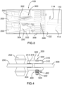
- Each finger conducting plate 306 is positioned relative to its corresponding conducting disk 200 so that the corresponding conducting disk 200 is sandwiched between the upper fingers 302 secured to the top face of the finger conducting plate 306 and the lower finger 304 secured to the top face of the finger conducting plate 306.
- the upper fingers 302 and the lower clips 304 form together a clip that is movably securable to a conducting disc 200. Since they are all made of electrically conducting material, the conducting disk 200, the fingers 302 and 304 and the finger conducting plate 306 are all electrically connected.
- the conducting disk 200 may rotate about its rotation axis while still being in physical contact with the fingers 302 and 304 so that an electrical current may flow between the conducting disk 200 and the finger conducting plate 306 via the fingers 302 and 304 during the rotation of the conducting disk 200.
- plate isolators 308 made of electrically insulating material fixedly secure the finger conducting plates 306 to the housing 102.
- a first plate isolator 308 extends a first end secured to the bottom wall of the housing 102 and a second end secured to the lowest finger conducting plate 306 to fixedly secure the lowest finger conducting plate 306 to the housing 102 and optionally electrically isolate the lowest finger conducting plate 306 from the housing 102.
- a plate isolator 308 is further inserted between two adjacent finger conducting plates 306 to fixedly secure the finger conducting plates 306 together and to the housing 102 via the lowest finger conducting plate 306.
- the lowest finger conducting plate 306 of each column is secured to the bottom wall of the housing 102 via at least one plate isolator 308.
- the fingers plate isolators 308 which secure the finger conducting plates 306 to the housing 102 are provided with a resilient element enabling slight independent bending motion of the fingers plates 306 with respect to the housing 102. This may be of great advantage in harsh vibrating environments wherein the conductors connected to the electrical connections 110 may be subjected to vibrations. Of course, other arrangements for mounting the fingers plates 306 could be used.
- the fingers plate isolators 308 could be made of epoxy, fiberglass or EPDM high creepage resistant material.
- the fingers plate isolators 308 could also be used as a system damping device when used in applications where vibrations are important. In such embodiment, EPDM high creepage resistant material may be preferred.
- each slip ring 300 has six upper conducting fingers 302 mounted side by side on the top face of the finger conducting plate 306 and six lower conducting fingers 304 mounted side by side on the finger conducting plate 306, it should be understood that he number of fingers may vary as long as a slip ring 300 comprises at least one upper finger 302 and/or at least one lower finger 304 In one embodiment, the number of conducting fingers 302 and 304 may be determined according to the required ampacity and short circuit level required in a given application.
- each of the upper and lower fingers 302 and 304 has a first end 310 with a rounded surface 312 for mounting on the finger conducting plate 306 and an opposite second end 314 for contacting the rotating conducting disk 200.
- the second end 314 is provided with a raised surface 316 devised to ease the physical contact with the conducting disk 200 even in an environment prone to vibrations as the one in a wind turbine, as it will become apparent below.
- each of the upper and lower conducting fingers 302 and 304 is made of copper that is silver plated.
- each of the conducting disks 200 is also provided with an outer upper silver plated surface 220 and an outer lower silver plated surface 222 therearound, respectively in contact with the upper and lower conducting fingers 302, 304, as shown in Figure 3
- the silver plating prevents oxidation of the aluminium of the conducting disks 200.
- the thickness of the silver plating may be determined as a function of the use of the slip ring. In other words, the mean time between maintenance could be lowered by a thicker silver plating, as it should become apparent to the skilled addressee.
- the slip ring assembly 100 is also provided with a plurality of resilient devices 400, each being mounted with a corresponding slip ring 300 for urging the corresponding conducting fingers 302 and 304 against the conducting disk 200 to maintain electrical connection therebetween and thereby provide an electrical connection between the conducting disk 200 and the electrical connection 110 provided at the opposed end of the finger conducting plate 306.
- each of the resilient devices 400 comprises at least one spring 402, each spring 402 being associated with a corresponding pair of upper and lower fingers 302, 304. More particularly, in one embodiment, as illustrated, each pair of facing upper and lower fingers 302 and 304 is provided with a spring 402 used to urge the fingers 302 and 304 against the disk surfaces 220 and 222 and against the finger conducting plate 306.
- a pass through bolt and screw assembly 500 is used to attached the fingers 302 and 304 to the fingers plate 306 and the spring 402 in mounted around the screw shaft 502 between the lower finger 304 and the bolt 504.
- the bolt 504 may be used to more or less tighten the fingers 302 and 304 and conducting disk 200 assembly. Such an embodiment may be of great interest in environments prone to vibrations.
- each of the rotating disks 200 will rotate accordingly, driven by the movements of the rigid conductors 210 connected to the generator while the housing 102 has a fixed position.
- the conducting discs 200 rotate inside the clips formed by the upper and lower fingers which are fixedly secured to the housing 102, thereby allowing electrical current to flow from the generator to the finger conducting plates 306 which are electrically connected to electrical conductors running along the pole of the wind turbine.
- Figure 6 shows first and second finger conducting plates 306 that may be used in the slip ring assembly 100 shown in Figure 1 through Figure 3 and using two columns of finger conducting plates 306 for providing two columns of electrical connections 110.
- finger conducting plates 306 can be mounted in longitudinal alignment with the center of the conducting disk 200.
- the finger conducting plates 306 may be rectangularly shaped with a straight edge at the second end extending proximate the corresponding conducting disk 200 and an opposite straight edge at the first end providing the electrical connection 110.
- the finger conducting plates 306 may be each provided with a first longitudinal rectangularly shaped portion 360 at the first end for providing parallel electrical connections 110 aligned outside the housing 102, and a second portion 362 angularly extending with respect to the first portion 360 at the second end, the second portion 362 extending in the direction of the center of the conducting disks 200 to ease electrical contact between the conducting fingers 302, 304 and the conducting disk 200.
- Other arrangements could be considered, as it should be apparent to the skilled addressee.
- the slip ring assembly 100 previously described may be of great advantage over the electrical arrangements of the prior art presently used since maintenance operations can be drastically reduced. For example, it is believed that such slip ring assembly 100 may be maintenance free for up to 40 years, which is of great advantage over the existing used solutions which require more frequent maintenance operations. Moreover, thanks to its specific design, the slip ring assembly 100 may be used in high ampacity and power applications requiring currents up to 2000A to 3000A. As it should now be apparent to the skilled addressee, the size of the conducting disks 200 and the number of conducting fingers 302 and 304 will determine the maximum ampacity and short-circuit level that can be handled by the slip ring assembly 100.
- the conducting discs are identical 200, it should be understood that other configurations are possible.
- the conducting discs 200 may be provided with an inner aperture of which the diameter varies from one conducting disc 200 another.
- the lowest conducting disc 200 is provided with the inner aperture having the smallest diameter and the diameter of the inner aperture increases from the lowest conducting disc 200 to the highest conducting disc 200.
- the position of the inner edge is offset in a direction orthogonal to the rotation axis from one conducting plate to an adjacent one.
- Each elongated electrical conductor 210 is then secured to a respective conducting disc 200 either directly to the conducting disc 200 adjacent to the inner edge thereof or to a protrusion (as described above) without being in physical contact with the other conducting discs 200.
- the offset between the inner edges of two adjacent conducting discs 200 is chosen as a function of the dimensions of the elongated electrical conductors 210 so that each elongated electrical conductor 210 be in physical contact only with a single conducting disc 200.
- the lateral wall of the housing 102 comprises four panels, it should be understood that the number of panels may vary.
- the side of the lateral wall on which slip rings are present may comprise no panel.
Landscapes
- Engineering & Computer Science (AREA)
- Life Sciences & Earth Sciences (AREA)
- Sustainable Energy (AREA)
- Sustainable Development (AREA)
- Chemical & Material Sciences (AREA)
- Combustion & Propulsion (AREA)
- Mechanical Engineering (AREA)
- General Engineering & Computer Science (AREA)
- Power Engineering (AREA)
- Ceramic Engineering (AREA)
- Motor Or Generator Current Collectors (AREA)
Claims (15)
- Ensemble de bague collectrice (100) pour connecter électriquement un générateur monté dans une nacelle rotative d'une éolienne orientable et des conducteurs de distribution électrique fixes montés à un poteau fixe de l'éolienne orientable, l'ensemble bague collectrice comprenant :une pluralité de disques conducteurs (200) espacés et montés empilés le long d'un axe de rotation commun, chacun pouvant être électriquement connecté à une sortie électrique respective du générateur et pouvant être fixé à demeure au générateur de telle sorte qu'une rotation de la nacelle rotative déclenche une rotation des disques conducteurs (200) ;une pluralité d'isolants électriques (202) de disque positionnés entre deux disques conducteurs (200) adjacents afin de les fixer ensemble et de les isoler électriquement les uns des autres ;
etune pluralité de dispositifs de bague collectrice (300), chacun pouvant être électriquement connecté et mécaniquement fixé à un respectif des conducteurs de distribution électrique fixes de manière à avoir une position fixe par rapport au poteau fixe, chacun de la pluralité de dispositifs de bague collectrice (300) comprenant au moins un doigt conducteur supérieur (302) et au moins un doigt conducteur inférieur (304) agencés de manière à recevoir de manière rotative un respectif de la pluralité de disques conducteurs (200) entre eux et à assurer une connexion électrique entre l'un respectif de la pluralité de disques conducteurs (200) et le dispositif de bague collectrice, une rotation de la nacelle déclenchant une rotation des disques conducteurs (200) par rapport à l'au moins un doigt conducteur supérieur (302) et à l'au moins un doigt conducteur inférieur (304) de telle sorte qu'un courant électrique s'écoule entre le générateur et les conducteurs de distribution électrique fixes durant la rotation de la nacelle ; caractérisé en ce que les isolants électriques (202) de disque sont composés d'un matériau caoutchouteux de sorte que les vibrations sont amorties par les isolants électriques (202) de disque. - Ensemble de bague collectrice (100) selon la revendication 1, comprenant en outre un boîtier (102) à positionner de manière à avoir une position fixe par rapport au poteau fixe, les disques conducteurs (200) étant positionnés dans le boîtier et pouvant tourner par rapport au boîtier.
- Ensemble de bague collectrice (100) selon la revendication 2, dans lequel le boîtier (102) comprend une première paroi dotée d'une ouverture de connexion (114), d'une deuxième paroi opposée à la première paroi et d'une paroi latérale s'étendant entre les première et deuxième parois, la deuxième paroi étant configurée pour être fixée au poteau fixe.
- Ensemble de bague collectrice (100) selon la revendication 3, dans lequel chacun de la pluralité de dispositifs de bague collectrice (300) comprend une plaque conductrice (306) s'étendant longitudinalement entre une première extrémité de plaque et une deuxième extrémité de plaque et ayant l'au moins un doigt conducteur supérieur (302) se projetant depuis la première extrémité de plaque et fixé sur une première face de celle-ci et l'au moins un doigt conducteur supérieur se projetant depuis la première extrémité de plaque et fixé sur une deuxième face de celle-ci, la deuxième face étant opposée à la première face, et la deuxième extrémité de plaque pouvant être électriquement connectée à un conducteur donné des conducteurs de distribution électrique fixes.
- Ensemble de bague collectrice (100) selon la revendication 4, dans lequel la paroi latérale est dotée d'une pluralité de trous de connexion destinés chacun à recevoir la plaque conductrice (306) d'un respectif de la pluralité de dispositifs de bague collectrice (300) dans ceux-ci.
- Ensemble de bague collectrice (100) selon l'une quelconque des revendications 3 à 5, dans lequel les disques conducteurs (200) sont fixés de manière rotative à la deuxième paroi du boîtier (102).
- Ensemble de bague collectrice (100) selon l'une quelconque des revendications 1 à 4, comprenant en outre une pluralité de conducteurs allongés (210) s'étendant chacun longitudinalement entre une première extrémité de connexion pouvant être connectée au générateur et une deuxième extrémité de connexion électriquement connectée à un respectif des disques conducteurs (200).
- Ensemble de bague collectrice (100) selon la revendication 7, dans lequel chacun des conducteurs allongés s'étend dans un tunnel formé par une ouverture intérieure (204) des disques conducteurs (200) jusqu'à l'un respectif des disques conducteurs (200) et à travers l'ouverture de connexion (114) de la première paroi du boîtier (102).
- Ensemble de bague collectrice (100) selon la revendication 8, dans lequel un diamètre de l'ouverture intérieure (204) est identique pour tous les disques conducteurs (200).
- Ensemble de bague collectrice (100) selon la revendication 9, dans lequel un bord intérieur (206) de chacun des disques conducteurs (200) est doté d'une section de montage se projetant vers l'intérieur, le conducteur allongé de deuxième extrémité de connexion étant fixé à la section de montage se projetant vers l'intérieur.
- Ensemble de bague collectrice (100) selon la revendication 8, dans lequel un diamètre de l'ouverture intérieure (204) varie d'un des disques conducteurs (200) à un autre des disques conducteurs (200).
- Ensemble de bague collectrice (100) selon l'une quelconque des revendications 7 à 11, comprenant en outre un couvercle (240) monté de manière rotative sur le boîtier (102) et comprenant une pluralité de trous conducteurs destinés chacun à recevoir un respectif des conducteurs allongés (210).
- Ensemble de bague collectrice (100) selon la revendication 4, comprenant en outre une pluralité de dispositifs élastiques (400) montés chacun avec un correspondant de la pluralité de dispositifs de bague collectrice (300) pour pousser l'au moins un doigt conducteur supérieur (302) et l'au moins un doigt conducteur inférieur (304) contre l'un respectif des disques conducteurs (200) pour maintenir la connexion électrique entre ceux-ci.
- Ensemble de bague collectrice (100) selon la revendication 13, dans lequel l'au moins un doigt conducteur supérieur comprend une pluralité de doigts supérieurs montés côte à côte et l'au moins un doigt conducteur inférieur comprend une pluralité de doigts inférieurs montés côte à côte et chacun étant associé à un respectif des doigts supérieurs pour former une pluralité de paires de doigts.
- Ensemble de bague collectrice (100) selon la revendication 14, dans lequel chacun des dispositifs élastiques (400) comprend une pluralité de ressorts (402) associés chacun à une respective des paires de doigts.
Applications Claiming Priority (2)
| Application Number | Priority Date | Filing Date | Title |
|---|---|---|---|
| US201862779745P | 2018-12-14 | 2018-12-14 | |
| PCT/IB2019/060796 WO2020121280A1 (fr) | 2018-12-14 | 2019-12-13 | Ensemble bague collectrice |
Publications (3)
| Publication Number | Publication Date |
|---|---|
| EP3895258A1 EP3895258A1 (fr) | 2021-10-20 |
| EP3895258A4 EP3895258A4 (fr) | 2022-08-17 |
| EP3895258B1 true EP3895258B1 (fr) | 2023-10-18 |
Family
ID=71076810
Family Applications (1)
| Application Number | Title | Priority Date | Filing Date |
|---|---|---|---|
| EP19897368.7A Active EP3895258B1 (fr) | 2018-12-14 | 2019-12-13 | Ensemble bague collectrice |
Country Status (5)
| Country | Link |
|---|---|
| US (1) | US11437896B2 (fr) |
| EP (1) | EP3895258B1 (fr) |
| CN (1) | CN113424375B (fr) |
| CA (1) | CA3083822C (fr) |
| WO (1) | WO2020121280A1 (fr) |
Families Citing this family (6)
| Publication number | Priority date | Publication date | Assignee | Title |
|---|---|---|---|---|
| WO2021041435A1 (fr) * | 2019-08-29 | 2021-03-04 | Cr Flight L.L.C. | Ensemble bague collectrice d'ensemble moteur électrique différentiel contrarotatif |
| NO348170B1 (en) * | 2023-02-21 | 2024-09-16 | Zinus As | Rotational position independent electrical coupling apparatus |
| DE102023126717B3 (de) * | 2023-09-29 | 2025-01-30 | Stemmann-Technik Gmbh | Schleifringübertragersystem |
| DE102023126726B3 (de) * | 2023-09-29 | 2025-01-30 | Stemmann-Technik Gmbh | Schleifringübertragersystem |
| DE102023126731B3 (de) * | 2023-09-29 | 2025-01-30 | Stemmann-Technik Gmbh | Schleifringübertragersystem |
| DE102023131652A1 (de) * | 2023-11-14 | 2025-05-15 | Liebherr-Hydraulikbagger Gmbh | Vorrichtung mit einer Drehverbindung |
Citations (2)
| Publication number | Priority date | Publication date | Assignee | Title |
|---|---|---|---|---|
| GB1031271A (en) * | 1964-01-02 | 1966-06-02 | Carbone Ltd | Improvements in contact brushes for electrical machines |
| JPH05144533A (ja) * | 1991-11-22 | 1993-06-11 | Alps Electric Co Ltd | スリツプリング |
Family Cites Families (16)
| Publication number | Priority date | Publication date | Assignee | Title |
|---|---|---|---|---|
| FR2471682A1 (fr) * | 1979-12-12 | 1981-06-19 | Sacre Louis | Perfectionnement aux collecteurs tournants a axe vertical |
| GB8429429D0 (en) * | 1984-11-21 | 1985-01-03 | English Electric Co Ltd | Turbine generator systems |
| FR2775840B1 (fr) * | 1998-03-06 | 2000-06-09 | Ferraz | Dispositif d'alimentation electrique et ensemble propulseur et directeur pour navire incorporant un tel dispositif |
| DE10106119A1 (de) * | 2001-02-08 | 2002-09-19 | Schunk Metall & Kunststoff | Stromübertragungsanordnung |
| US8593010B2 (en) * | 2009-01-13 | 2013-11-26 | Vestas Wind Systems A/S | Wind turbine |
| DE102011003038A1 (de) * | 2011-01-24 | 2012-07-26 | Siemens Aktiengesellschaft | Windkraftgenerator mit Gleitlager und Axial-Schleifringvorrichtung |
| JP2013096257A (ja) * | 2011-10-28 | 2013-05-20 | Nippon Densan Corp | 風力発電装置 |
| DE102012220293A1 (de) * | 2012-11-07 | 2014-05-08 | Wobben Properties Gmbh | Schleifringübertrager |
| CN105102812A (zh) * | 2013-03-05 | 2015-11-25 | 奥金公司 | 具有滑环的流体涡轮机 |
| CN104218419B (zh) * | 2013-05-29 | 2017-09-22 | 中航光电科技股份有限公司 | 接触簧片以及使用该接触簧片的电刷接触件 |
| KR101531997B1 (ko) * | 2013-09-27 | 2015-06-26 | 연합정밀주식회사 | 슬립링 회전본체의 제조장치 및 이를 이용한 슬립링 회전본체의 제조방법 |
| US20150180186A1 (en) * | 2013-12-20 | 2015-06-25 | Google Inc. | Systems and Apparatus for Cable Management |
| WO2015187107A1 (fr) * | 2014-06-05 | 2015-12-10 | Eae Elektri̇k Asansör Endüstri̇si̇ İnşaat Sanayi̇ Ve Ti̇caret Anoni̇m Şi̇rketi̇ | Câble de transport de mécanisme de liaison rotatif dans les turbines éoliennes |
| CN104362488A (zh) * | 2014-11-05 | 2015-02-18 | 郑州森源新能源科技有限公司 | 水平轴风力发电机的换向装置 |
| CN105337132B (zh) * | 2015-11-18 | 2017-11-14 | 西北工业大学 | 风电主功率滑环 |
| RU168408U1 (ru) * | 2016-10-14 | 2017-02-02 | Александр Сергеевич Гущин | Токоприемник кольцевой |
-
2019
- 2019-12-13 WO PCT/IB2019/060796 patent/WO2020121280A1/fr not_active Ceased
- 2019-12-13 US US16/764,734 patent/US11437896B2/en active Active
- 2019-12-13 CN CN201980092111.0A patent/CN113424375B/zh not_active Expired - Fee Related
- 2019-12-13 EP EP19897368.7A patent/EP3895258B1/fr active Active
- 2019-12-13 CA CA3083822A patent/CA3083822C/fr active Active
Patent Citations (2)
| Publication number | Priority date | Publication date | Assignee | Title |
|---|---|---|---|---|
| GB1031271A (en) * | 1964-01-02 | 1966-06-02 | Carbone Ltd | Improvements in contact brushes for electrical machines |
| JPH05144533A (ja) * | 1991-11-22 | 1993-06-11 | Alps Electric Co Ltd | スリツプリング |
Also Published As
| Publication number | Publication date |
|---|---|
| CN113424375B (zh) | 2023-03-03 |
| EP3895258A1 (fr) | 2021-10-20 |
| CA3083822A1 (fr) | 2020-06-18 |
| US20210218319A1 (en) | 2021-07-15 |
| WO2020121280A1 (fr) | 2020-06-18 |
| US11437896B2 (en) | 2022-09-06 |
| EP3895258A4 (fr) | 2022-08-17 |
| CA3083822C (fr) | 2021-06-01 |
| CN113424375A (zh) | 2021-09-21 |
Similar Documents
| Publication | Publication Date | Title |
|---|---|---|
| EP3895258B1 (fr) | Ensemble bague collectrice | |
| CN104078264B (zh) | 旋转式电气开关 | |
| CN102292897B (zh) | 用于轴向场装置的扇块式定子 | |
| CA1181120A (fr) | Bobinage d'extremite pour rotor et support | |
| EP2566012A2 (fr) | Stator de moteur | |
| CN102273024B (zh) | 具有层叠的环形导体组件的高电压旋转接头 | |
| KR101812154B1 (ko) | 송전선로 고정철탑의 댐퍼장치 | |
| JP2012237208A (ja) | 風車 | |
| CN111919363A (zh) | 交流电机与变流器单元的组合和风力发电设备 | |
| CN113285320A (zh) | 旋转导电装置及风力发电机组 | |
| HK40060358A (en) | A slip ring assembly | |
| HK40060358B (en) | A slip ring assembly | |
| US4782316A (en) | Core winding with inorganic insulation between the inner conductor and outer metal sheath | |
| EP3793042A1 (fr) | Ensemble de contact | |
| US20240006862A1 (en) | Submarine connection box for submarine power cables | |
| RU2064082C1 (ru) | Ветросиловая установка | |
| CN217405882U (zh) | 一种360度可旋转多路防爆滑环集电器 | |
| US11404957B2 (en) | Mounting of power cables for limiting common mode currents | |
| KR102362583B1 (ko) | 슬립링 조립체 | |
| CN1515062A (zh) | 具有汇流排导管组件的高功率旋转变压器 | |
| US9287072B2 (en) | Electric current switching apparatus | |
| EP3567247A1 (fr) | Connecteur électrique pour une éolienne | |
| EP3196901B1 (fr) | Ensemble à haute tension | |
| US7709993B2 (en) | Continuous direct current generator | |
| KR20240139577A (ko) | 전력 공급용 부스웨이 및 이를 포함하는 부스웨이 시스템 |
Legal Events
| Date | Code | Title | Description |
|---|---|---|---|
| STAA | Information on the status of an ep patent application or granted ep patent |
Free format text: STATUS: THE INTERNATIONAL PUBLICATION HAS BEEN MADE |
|
| PUAI | Public reference made under article 153(3) epc to a published international application that has entered the european phase |
Free format text: ORIGINAL CODE: 0009012 |
|
| STAA | Information on the status of an ep patent application or granted ep patent |
Free format text: STATUS: REQUEST FOR EXAMINATION WAS MADE |
|
| 17P | Request for examination filed |
Effective date: 20210714 |
|
| AK | Designated contracting states |
Kind code of ref document: A1 Designated state(s): AL AT BE BG CH CY CZ DE DK EE ES FI FR GB GR HR HU IE IS IT LI LT LU LV MC MK MT NL NO PL PT RO RS SE SI SK SM TR |
|
| DAV | Request for validation of the european patent (deleted) | ||
| DAX | Request for extension of the european patent (deleted) | ||
| A4 | Supplementary search report drawn up and despatched |
Effective date: 20220719 |
|
| RIC1 | Information provided on ipc code assigned before grant |
Ipc: H01R 39/26 20060101ALN20220713BHEP Ipc: F03D 80/80 20160101ALI20220713BHEP Ipc: H01R 39/64 20060101ALI20220713BHEP Ipc: H01R 39/10 20060101AFI20220713BHEP |
|
| RIC1 | Information provided on ipc code assigned before grant |
Ipc: H01R 39/26 20060101ALN20230504BHEP Ipc: F03D 80/00 20160101ALI20230504BHEP Ipc: F03D 80/80 20160101ALI20230504BHEP Ipc: H01R 39/64 20060101ALI20230504BHEP Ipc: H01R 39/10 20060101AFI20230504BHEP |
|
| GRAP | Despatch of communication of intention to grant a patent |
Free format text: ORIGINAL CODE: EPIDOSNIGR1 |
|
| STAA | Information on the status of an ep patent application or granted ep patent |
Free format text: STATUS: GRANT OF PATENT IS INTENDED |
|
| RIC1 | Information provided on ipc code assigned before grant |
Ipc: H01R 39/26 20060101ALN20230526BHEP Ipc: F03D 80/00 20160101ALI20230526BHEP Ipc: F03D 80/80 20160101ALI20230526BHEP Ipc: H01R 39/64 20060101ALI20230526BHEP Ipc: H01R 39/10 20060101AFI20230526BHEP |
|
| INTG | Intention to grant announced |
Effective date: 20230615 |
|
| GRAS | Grant fee paid |
Free format text: ORIGINAL CODE: EPIDOSNIGR3 |
|
| GRAA | (expected) grant |
Free format text: ORIGINAL CODE: 0009210 |
|
| STAA | Information on the status of an ep patent application or granted ep patent |
Free format text: STATUS: THE PATENT HAS BEEN GRANTED |
|
| AK | Designated contracting states |
Kind code of ref document: B1 Designated state(s): AL AT BE BG CH CY CZ DE DK EE ES FI FR GB GR HR HU IE IS IT LI LT LU LV MC MK MT NL NO PL PT RO RS SE SI SK SM TR |
|
| REG | Reference to a national code |
Ref country code: GB Ref legal event code: FG4D |
|
| REG | Reference to a national code |
Ref country code: CH Ref legal event code: EP |
|
| REG | Reference to a national code |
Ref country code: DE Ref legal event code: R096 Ref document number: 602019039844 Country of ref document: DE |
|
| REG | Reference to a national code |
Ref country code: IE Ref legal event code: FG4D |
|
| REG | Reference to a national code |
Ref country code: LT Ref legal event code: MG9D |
|
| REG | Reference to a national code |
Ref country code: NL Ref legal event code: MP Effective date: 20231018 |
|
| REG | Reference to a national code |
Ref country code: AT Ref legal event code: MK05 Ref document number: 1623315 Country of ref document: AT Kind code of ref document: T Effective date: 20231018 |
|
| PG25 | Lapsed in a contracting state [announced via postgrant information from national office to epo] |
Ref country code: NL Free format text: LAPSE BECAUSE OF FAILURE TO SUBMIT A TRANSLATION OF THE DESCRIPTION OR TO PAY THE FEE WITHIN THE PRESCRIBED TIME-LIMIT Effective date: 20231018 |
|
| PG25 | Lapsed in a contracting state [announced via postgrant information from national office to epo] |
Ref country code: GR Free format text: LAPSE BECAUSE OF FAILURE TO SUBMIT A TRANSLATION OF THE DESCRIPTION OR TO PAY THE FEE WITHIN THE PRESCRIBED TIME-LIMIT Effective date: 20240119 |
|
| PG25 | Lapsed in a contracting state [announced via postgrant information from national office to epo] |
Ref country code: IS Free format text: LAPSE BECAUSE OF FAILURE TO SUBMIT A TRANSLATION OF THE DESCRIPTION OR TO PAY THE FEE WITHIN THE PRESCRIBED TIME-LIMIT Effective date: 20240218 |
|
| PG25 | Lapsed in a contracting state [announced via postgrant information from national office to epo] |
Ref country code: LT Free format text: LAPSE BECAUSE OF FAILURE TO SUBMIT A TRANSLATION OF THE DESCRIPTION OR TO PAY THE FEE WITHIN THE PRESCRIBED TIME-LIMIT Effective date: 20231018 |
|
| PG25 | Lapsed in a contracting state [announced via postgrant information from national office to epo] |
Ref country code: AT Free format text: LAPSE BECAUSE OF FAILURE TO SUBMIT A TRANSLATION OF THE DESCRIPTION OR TO PAY THE FEE WITHIN THE PRESCRIBED TIME-LIMIT Effective date: 20231018 |
|
| PG25 | Lapsed in a contracting state [announced via postgrant information from national office to epo] |
Ref country code: ES Free format text: LAPSE BECAUSE OF FAILURE TO SUBMIT A TRANSLATION OF THE DESCRIPTION OR TO PAY THE FEE WITHIN THE PRESCRIBED TIME-LIMIT Effective date: 20231018 |
|
| PG25 | Lapsed in a contracting state [announced via postgrant information from national office to epo] |
Ref country code: LT Free format text: LAPSE BECAUSE OF FAILURE TO SUBMIT A TRANSLATION OF THE DESCRIPTION OR TO PAY THE FEE WITHIN THE PRESCRIBED TIME-LIMIT Effective date: 20231018 Ref country code: IS Free format text: LAPSE BECAUSE OF FAILURE TO SUBMIT A TRANSLATION OF THE DESCRIPTION OR TO PAY THE FEE WITHIN THE PRESCRIBED TIME-LIMIT Effective date: 20240218 Ref country code: GR Free format text: LAPSE BECAUSE OF FAILURE TO SUBMIT A TRANSLATION OF THE DESCRIPTION OR TO PAY THE FEE WITHIN THE PRESCRIBED TIME-LIMIT Effective date: 20240119 Ref country code: ES Free format text: LAPSE BECAUSE OF FAILURE TO SUBMIT A TRANSLATION OF THE DESCRIPTION OR TO PAY THE FEE WITHIN THE PRESCRIBED TIME-LIMIT Effective date: 20231018 Ref country code: BG Free format text: LAPSE BECAUSE OF FAILURE TO SUBMIT A TRANSLATION OF THE DESCRIPTION OR TO PAY THE FEE WITHIN THE PRESCRIBED TIME-LIMIT Effective date: 20240118 Ref country code: AT Free format text: LAPSE BECAUSE OF FAILURE TO SUBMIT A TRANSLATION OF THE DESCRIPTION OR TO PAY THE FEE WITHIN THE PRESCRIBED TIME-LIMIT Effective date: 20231018 Ref country code: PT Free format text: LAPSE BECAUSE OF FAILURE TO SUBMIT A TRANSLATION OF THE DESCRIPTION OR TO PAY THE FEE WITHIN THE PRESCRIBED TIME-LIMIT Effective date: 20240219 |
|
| PGFP | Annual fee paid to national office [announced via postgrant information from national office to epo] |
Ref country code: DE Payment date: 20240112 Year of fee payment: 5 |
|
| PG25 | Lapsed in a contracting state [announced via postgrant information from national office to epo] |
Ref country code: SE Free format text: LAPSE BECAUSE OF FAILURE TO SUBMIT A TRANSLATION OF THE DESCRIPTION OR TO PAY THE FEE WITHIN THE PRESCRIBED TIME-LIMIT Effective date: 20231018 Ref country code: RS Free format text: LAPSE BECAUSE OF FAILURE TO SUBMIT A TRANSLATION OF THE DESCRIPTION OR TO PAY THE FEE WITHIN THE PRESCRIBED TIME-LIMIT Effective date: 20231018 Ref country code: PL Free format text: LAPSE BECAUSE OF FAILURE TO SUBMIT A TRANSLATION OF THE DESCRIPTION OR TO PAY THE FEE WITHIN THE PRESCRIBED TIME-LIMIT Effective date: 20231018 Ref country code: NO Free format text: LAPSE BECAUSE OF FAILURE TO SUBMIT A TRANSLATION OF THE DESCRIPTION OR TO PAY THE FEE WITHIN THE PRESCRIBED TIME-LIMIT Effective date: 20240118 Ref country code: LV Free format text: LAPSE BECAUSE OF FAILURE TO SUBMIT A TRANSLATION OF THE DESCRIPTION OR TO PAY THE FEE WITHIN THE PRESCRIBED TIME-LIMIT Effective date: 20231018 Ref country code: HR Free format text: LAPSE BECAUSE OF FAILURE TO SUBMIT A TRANSLATION OF THE DESCRIPTION OR TO PAY THE FEE WITHIN THE PRESCRIBED TIME-LIMIT Effective date: 20231018 |
|
| PGFP | Annual fee paid to national office [announced via postgrant information from national office to epo] |
Ref country code: FR Payment date: 20240105 Year of fee payment: 5 |
|
| PG25 | Lapsed in a contracting state [announced via postgrant information from national office to epo] |
Ref country code: DK Free format text: LAPSE BECAUSE OF FAILURE TO SUBMIT A TRANSLATION OF THE DESCRIPTION OR TO PAY THE FEE WITHIN THE PRESCRIBED TIME-LIMIT Effective date: 20231018 |
|
| REG | Reference to a national code |
Ref country code: DE Ref legal event code: R097 Ref document number: 602019039844 Country of ref document: DE |
|
| PG25 | Lapsed in a contracting state [announced via postgrant information from national office to epo] |
Ref country code: CZ Free format text: LAPSE BECAUSE OF FAILURE TO SUBMIT A TRANSLATION OF THE DESCRIPTION OR TO PAY THE FEE WITHIN THE PRESCRIBED TIME-LIMIT Effective date: 20231018 |
|
| PG25 | Lapsed in a contracting state [announced via postgrant information from national office to epo] |
Ref country code: SK Free format text: LAPSE BECAUSE OF FAILURE TO SUBMIT A TRANSLATION OF THE DESCRIPTION OR TO PAY THE FEE WITHIN THE PRESCRIBED TIME-LIMIT Effective date: 20231018 |
|
| PG25 | Lapsed in a contracting state [announced via postgrant information from national office to epo] |
Ref country code: SM Free format text: LAPSE BECAUSE OF FAILURE TO SUBMIT A TRANSLATION OF THE DESCRIPTION OR TO PAY THE FEE WITHIN THE PRESCRIBED TIME-LIMIT Effective date: 20231018 Ref country code: SK Free format text: LAPSE BECAUSE OF FAILURE TO SUBMIT A TRANSLATION OF THE DESCRIPTION OR TO PAY THE FEE WITHIN THE PRESCRIBED TIME-LIMIT Effective date: 20231018 Ref country code: RO Free format text: LAPSE BECAUSE OF FAILURE TO SUBMIT A TRANSLATION OF THE DESCRIPTION OR TO PAY THE FEE WITHIN THE PRESCRIBED TIME-LIMIT Effective date: 20231018 Ref country code: IT Free format text: LAPSE BECAUSE OF FAILURE TO SUBMIT A TRANSLATION OF THE DESCRIPTION OR TO PAY THE FEE WITHIN THE PRESCRIBED TIME-LIMIT Effective date: 20231018 Ref country code: EE Free format text: LAPSE BECAUSE OF FAILURE TO SUBMIT A TRANSLATION OF THE DESCRIPTION OR TO PAY THE FEE WITHIN THE PRESCRIBED TIME-LIMIT Effective date: 20231018 Ref country code: DK Free format text: LAPSE BECAUSE OF FAILURE TO SUBMIT A TRANSLATION OF THE DESCRIPTION OR TO PAY THE FEE WITHIN THE PRESCRIBED TIME-LIMIT Effective date: 20231018 Ref country code: CZ Free format text: LAPSE BECAUSE OF FAILURE TO SUBMIT A TRANSLATION OF THE DESCRIPTION OR TO PAY THE FEE WITHIN THE PRESCRIBED TIME-LIMIT Effective date: 20231018 |
|
| REG | Reference to a national code |
Ref country code: CH Ref legal event code: PL |
|
| PLBE | No opposition filed within time limit |
Free format text: ORIGINAL CODE: 0009261 |
|
| STAA | Information on the status of an ep patent application or granted ep patent |
Free format text: STATUS: NO OPPOSITION FILED WITHIN TIME LIMIT |
|
| PG25 | Lapsed in a contracting state [announced via postgrant information from national office to epo] |
Ref country code: LU Free format text: LAPSE BECAUSE OF NON-PAYMENT OF DUE FEES Effective date: 20231213 |
|
| PG25 | Lapsed in a contracting state [announced via postgrant information from national office to epo] |
Ref country code: MC Free format text: LAPSE BECAUSE OF FAILURE TO SUBMIT A TRANSLATION OF THE DESCRIPTION OR TO PAY THE FEE WITHIN THE PRESCRIBED TIME-LIMIT Effective date: 20231018 |
|
| REG | Reference to a national code |
Ref country code: BE Ref legal event code: MM Effective date: 20231231 |
|
| PG25 | Lapsed in a contracting state [announced via postgrant information from national office to epo] |
Ref country code: MC Free format text: LAPSE BECAUSE OF FAILURE TO SUBMIT A TRANSLATION OF THE DESCRIPTION OR TO PAY THE FEE WITHIN THE PRESCRIBED TIME-LIMIT Effective date: 20231018 Ref country code: LU Free format text: LAPSE BECAUSE OF NON-PAYMENT OF DUE FEES Effective date: 20231213 |
|
| 26N | No opposition filed |
Effective date: 20240719 |
|
| GBPC | Gb: european patent ceased through non-payment of renewal fee |
Effective date: 20240118 |
|
| REG | Reference to a national code |
Ref country code: IE Ref legal event code: MM4A |
|
| PG25 | Lapsed in a contracting state [announced via postgrant information from national office to epo] |
Ref country code: IE Free format text: LAPSE BECAUSE OF NON-PAYMENT OF DUE FEES Effective date: 20231213 |
|
| PG25 | Lapsed in a contracting state [announced via postgrant information from national office to epo] |
Ref country code: GB Free format text: LAPSE BECAUSE OF NON-PAYMENT OF DUE FEES Effective date: 20240118 |
|
| PG25 | Lapsed in a contracting state [announced via postgrant information from national office to epo] |
Ref country code: BE Free format text: LAPSE BECAUSE OF NON-PAYMENT OF DUE FEES Effective date: 20231231 |
|
| PG25 | Lapsed in a contracting state [announced via postgrant information from national office to epo] |
Ref country code: CH Free format text: LAPSE BECAUSE OF NON-PAYMENT OF DUE FEES Effective date: 20231231 |
|
| PG25 | Lapsed in a contracting state [announced via postgrant information from national office to epo] |
Ref country code: SI Free format text: LAPSE BECAUSE OF FAILURE TO SUBMIT A TRANSLATION OF THE DESCRIPTION OR TO PAY THE FEE WITHIN THE PRESCRIBED TIME-LIMIT Effective date: 20231018 |
|
| PG25 | Lapsed in a contracting state [announced via postgrant information from national office to epo] |
Ref country code: SI Free format text: LAPSE BECAUSE OF FAILURE TO SUBMIT A TRANSLATION OF THE DESCRIPTION OR TO PAY THE FEE WITHIN THE PRESCRIBED TIME-LIMIT Effective date: 20231018 Ref country code: IE Free format text: LAPSE BECAUSE OF NON-PAYMENT OF DUE FEES Effective date: 20231213 Ref country code: GB Free format text: LAPSE BECAUSE OF NON-PAYMENT OF DUE FEES Effective date: 20240118 Ref country code: CH Free format text: LAPSE BECAUSE OF NON-PAYMENT OF DUE FEES Effective date: 20231231 Ref country code: BE Free format text: LAPSE BECAUSE OF NON-PAYMENT OF DUE FEES Effective date: 20231231 |
|
| REG | Reference to a national code |
Ref country code: DE Ref legal event code: R119 Ref document number: 602019039844 Country of ref document: DE |
|
| PG25 | Lapsed in a contracting state [announced via postgrant information from national office to epo] |
Ref country code: FI Free format text: LAPSE BECAUSE OF FAILURE TO SUBMIT A TRANSLATION OF THE DESCRIPTION OR TO PAY THE FEE WITHIN THE PRESCRIBED TIME-LIMIT Effective date: 20231019 |
|
| PG25 | Lapsed in a contracting state [announced via postgrant information from national office to epo] |
Ref country code: CY Free format text: LAPSE BECAUSE OF FAILURE TO SUBMIT A TRANSLATION OF THE DESCRIPTION OR TO PAY THE FEE WITHIN THE PRESCRIBED TIME-LIMIT; INVALID AB INITIO Effective date: 20191213 |
|
| PG25 | Lapsed in a contracting state [announced via postgrant information from national office to epo] |
Ref country code: HU Free format text: LAPSE BECAUSE OF FAILURE TO SUBMIT A TRANSLATION OF THE DESCRIPTION OR TO PAY THE FEE WITHIN THE PRESCRIBED TIME-LIMIT; INVALID AB INITIO Effective date: 20191213 |
|
| PG25 | Lapsed in a contracting state [announced via postgrant information from national office to epo] |
Ref country code: DE Free format text: LAPSE BECAUSE OF NON-PAYMENT OF DUE FEES Effective date: 20250701 |
|
| PG25 | Lapsed in a contracting state [announced via postgrant information from national office to epo] |
Ref country code: FR Free format text: LAPSE BECAUSE OF NON-PAYMENT OF DUE FEES Effective date: 20241231 |
|
| PG25 | Lapsed in a contracting state [announced via postgrant information from national office to epo] |
Ref country code: TR Free format text: LAPSE BECAUSE OF FAILURE TO SUBMIT A TRANSLATION OF THE DESCRIPTION OR TO PAY THE FEE WITHIN THE PRESCRIBED TIME-LIMIT Effective date: 20231018 |