EP3896706A1 - Noyau de fer pour appareil à induction fixe et appareil à induction fixe - Google Patents
Noyau de fer pour appareil à induction fixe et appareil à induction fixe Download PDFInfo
- Publication number
- EP3896706A1 EP3896706A1 EP19895918.1A EP19895918A EP3896706A1 EP 3896706 A1 EP3896706 A1 EP 3896706A1 EP 19895918 A EP19895918 A EP 19895918A EP 3896706 A1 EP3896706 A1 EP 3896706A1
- Authority
- EP
- European Patent Office
- Prior art keywords
- electromagnetic steel
- iron core
- steel plates
- magnetic domain
- parts
- Prior art date
- Legal status (The legal status is an assumption and is not a legal conclusion. Google has not performed a legal analysis and makes no representation as to the accuracy of the status listed.)
- Pending
Links
Images


Classifications
-
- H—ELECTRICITY
- H01—ELECTRIC ELEMENTS
- H01F—MAGNETS; INDUCTANCES; TRANSFORMERS; SELECTION OF MATERIALS FOR THEIR MAGNETIC PROPERTIES
- H01F27/00—Details of transformers or inductances, in general
- H01F27/24—Magnetic cores
- H01F27/245—Magnetic cores made from sheets, e.g. grain-oriented
-
- H—ELECTRICITY
- H01—ELECTRIC ELEMENTS
- H01F—MAGNETS; INDUCTANCES; TRANSFORMERS; SELECTION OF MATERIALS FOR THEIR MAGNETIC PROPERTIES
- H01F27/00—Details of transformers or inductances, in general
- H01F27/24—Magnetic cores
- H01F27/245—Magnetic cores made from sheets, e.g. grain-oriented
- H01F27/2455—Magnetic cores made from sheets, e.g. grain-oriented using bent laminations
-
- H—ELECTRICITY
- H01—ELECTRIC ELEMENTS
- H01F—MAGNETS; INDUCTANCES; TRANSFORMERS; SELECTION OF MATERIALS FOR THEIR MAGNETIC PROPERTIES
- H01F41/00—Apparatus or processes specially adapted for manufacturing or assembling magnets, inductances or transformers; Apparatus or processes specially adapted for manufacturing materials characterised by their magnetic properties
- H01F41/02—Apparatus or processes specially adapted for manufacturing or assembling magnets, inductances or transformers; Apparatus or processes specially adapted for manufacturing materials characterised by their magnetic properties for manufacturing cores, coils, or magnets
- H01F41/0206—Manufacturing of magnetic cores by mechanical means
- H01F41/0233—Manufacturing of magnetic circuits made from sheets
- H01F41/024—Manufacturing of magnetic circuits made from deformed sheets
-
- H—ELECTRICITY
- H01—ELECTRIC ELEMENTS
- H01F—MAGNETS; INDUCTANCES; TRANSFORMERS; SELECTION OF MATERIALS FOR THEIR MAGNETIC PROPERTIES
- H01F1/00—Magnets or magnetic bodies characterised by the magnetic materials therefor; Selection of materials for their magnetic properties
- H01F1/01—Magnets or magnetic bodies characterised by the magnetic materials therefor; Selection of materials for their magnetic properties of inorganic materials
- H01F1/03—Magnets or magnetic bodies characterised by the magnetic materials therefor; Selection of materials for their magnetic properties of inorganic materials characterised by their coercivity
- H01F1/12—Magnets or magnetic bodies characterised by the magnetic materials therefor; Selection of materials for their magnetic properties of inorganic materials characterised by their coercivity of soft-magnetic materials
- H01F1/14—Magnets or magnetic bodies characterised by the magnetic materials therefor; Selection of materials for their magnetic properties of inorganic materials characterised by their coercivity of soft-magnetic materials metals or alloys
- H01F1/16—Magnets or magnetic bodies characterised by the magnetic materials therefor; Selection of materials for their magnetic properties of inorganic materials characterised by their coercivity of soft-magnetic materials metals or alloys in the form of sheets
Definitions
- Embodiments of the present invention relate to an iron core for a stationary induction apparatus and a stationary induction apparatus.
- iron cores of stationary induction apparatuses for example, transformers, so-called laminated iron cores configured by laminating a plurality of electromagnetic steel plates such as silicon steel plates are known.
- laminated iron cores for a three-phase transformer three leg parts and upper and lower yoke parts are joined. It has been pointed out that, at this time, particularly at the joint part between the central leg part and the yoke part, a rotational magnetic flux in a direction different from the rolling direction of the electromagnetic steel plate occurs, which increases the loss, that is, iron loss.
- Patent Literature 1 therefore makes a proposition to perform magnetic domain fine differentiation control by subjecting the surface of the electromagnetic steel plate constituting the laminated iron core to magnetic domain fine differentiation which involves laser irradiation in a grid pattern of the vertical and horizontal directions with respect to the rolling direction in order to reduce the loss.
- Patent Literature 1 Japanese Patent Laid-Open No. 2015-106631
- one type of the iron cores for transformers is so-called one-turn cut type wound iron cores which are formed by winding a plurality of strip-like electromagnetic steel plates while providing at least one butt joint part for each winding.
- wound iron cores for example, butt joint parts are provided in a lower yoke part, and at the joint parts, electromagnetic steel plates are wound in a stepwise staggered manner.
- a nonmagnetic sheet member is located at the joint part to provide an air gap of a fixed width.
- the iron core can be not only the aforementioned wound iron core but also a laminated iron core configured by laminating a plurality of electromagnetic steel plates, forming yoke parts and leg parts and making them abut one another into a frame shape at the joint parts.
- This laminated iron core also has step-lap joint parts at which the butt joint parts between the yoke part and the leg part are disposed in a stepwise staggered manner in the stacking direction, which causes the problem that a loss occurs at the joint parts.
- an iron core for stationary induction apparatus and a stationary induction apparatus is configured by laminating a plurality of electromagnetic steel plates that are laminated so that the joint parts at which the end portions of the electromagnetic steel plates abut one another are disposed in a staggered manner, whereby the loss due to magnetic resistance at the joint parts can be kept low.
- An iron core for a stationary induction apparatus is configured by laminating a plurality of electromagnetic steel plates.
- the electromagnetic steel plates are laminated so that joint parts, at which the end portions of the electromagnetic steel plates abut one another, are disposed in a staggered manner; and the electromagnetic steel plates are provided with a magnetic domain fine differentiation processed part, which is located on the portion, of a surface of the end portion of each of the electromagnetic steel plates, lapped with the joint part of another electromagnetic steel plate, and which has been subjected to warping-derived magnetic domain fine differentiation.
- Figure 1 shows the overall configuration of a wound iron core 1 for a transformer as an iron core for a stationary induction apparatus according to this embodiment.
- This wound iron core 1 in a rectangular annular shape with rounded corners has two leg parts 2 and 2 extending in the up-and-down direction in the drawing, and yoke parts 3 and 3 connecting the upper end portions and the lower end portions of the leg parts 2 and 2 in the left-and-right direction.
- a winding 4 (represented by an imaginary line) is mounted to each of the leg parts 2 and 2.
- this wound iron core 1 is of a so-called one-turn cut type.
- the wound iron core 1 is formed by cutting a strip member 5 that is a strip-like electromagnetic steel plate, for example, a silicon steel plate, into a required size for each roll, and winding and laminating each sheet of strip member 5 in the inner and outer peripheral direction while providing a joint part 6 where their end portions abut one another.
- An oriented electromagnetic steel plate is used for each strip member 5, and the longitudinal direction, that is, the winding direction coincides with the rolling direction.
- the joint parts 6 are configured to come to the central portion of the lower yoke part 3, and as shown in Figure 2 , the joint parts 6 are laminated so that they are lapped with each other stepwise and displaced by a fixed pitch p in the winding direction, that is, the radial direction of the strip members 5.
- the joint parts 6 are sequentially displaced to the right in the drawing from the inner peripheral side to the outer peripheral side.
- the yoke part 3 is divided into a plurality of blocks in the winding direction, or two blocks in the drawing, and the joint parts 6 are repeatedly disposed stepwise.
- a sheet-like magnetic insulator is disposed at each joint part 6 to provide an air gap of a predetermined size.
- magnetic domain fine differentiation processed parts 7 that have been subjected to warping-derived magnetic domain fine differentiation are provided in positions lapped with the joint parts 6 of the other strip members 5 on the surfaces of the end portions of the strip members 5.
- the magnetic domain fine differentiation processed parts 7 are represented by the fine jagged lines for convenience in Figure 2 .
- Each magnetic domain fine differentiation processed part 7 is provided on one side, in this case, the right side of the corresponding joint part 6 and on one surface, in the drawing, the lower surface side of the end portion of the strip member 5.
- the magnetic domain fine differentiation processed part 7 is provided within a certain range, for example, in a range of a length of about twice the pitch p of the displacement of the joint part 6 all over in the width direction of the strip member 5. This range is defined as a range in which each magnetic flux ⁇ lies over another overlapping strip member 5 on the surface of the end portion of the strip member 5.
- magnetic fluxes ⁇ are represented by thin lines only in the upper four strip members 5.
- the magnetic domain fine differentiation processed parts 7 are formed by subjecting the lower surface of the end portion of each strip member 5 to continuous linear laser irradiation in a grid pattern in two directions orthogonal to each other. Consequently, linear marks L1 and L2 due to laser irradiation are formed on the lower surface of the end portion of the strip member 5.
- many linear marks L1 extend in the rolling direction of the strip member 5 in parallel at a predetermined interval s.
- many linear marks L2 also extend in the direction orthogonal to the linear marks L1, in this case, in the direction orthogonal to the rolling direction of the strip members 5 in parallel at a predetermined interval s.
- the interval s at which the linear marks L1 and L2 are formed is, for example, 2.0 mm or less.
- the laser irradiation on the electromagnetic steel plate, that is, the strip members 5 can be performed using a well-known general-purpose laser irradiation device.
- the conditions of the laser irradiation at this time are disclosed, for example, in Japanese Patent Application Publication No. 2015-106631 (paragraph [0023], Figure 8 ), and the description thereof is therefore omitted here.
- assembling of the wound iron core 1 includes cutting the strip members 5 of a predetermined width into a required length, and subjecting the surfaces of the end portion of the strip members 5, that is, the lower surface sides to laser irradiation to form the magnetic domain fine differentiation processed parts 7. Subsequently, the strip members 5 provided with the magnetic domain fine differentiation processed parts 7 are wound into a quadrangular annular shape, for example, in order, peripherally innermost first so that the end portion is located at the lower yoke part 3. In this case, the strip members 5 are wound and closely laminated one by one, from the peripherally innermost toward the outermost.
- the joint parts 6 are formed so that both end portions of each strip member 5 are close to each other.
- the strip members 5 are wound while the joint parts 6 are positioned so that they are located stepwise.
- the wound iron core 1 with the joint parts 6 disposed in a stepwise staggered manner in the winding direction of the strip members 5.
- the magnetic domain fine differentiation processed parts 7 on the lower surfaces of the strip members 5 located on the upper surfaces of the joint parts 6 are positioned so as to be lapped with the joint parts 6.
- the wound iron core 1 with the aforementioned configuration has joint parts 6 where the end portions of the strip members 5 abut one another in the lower yoke part 3, as only the upper half shows, each magnetic flux ⁇ at the joint part 6 flows across the strip members 5 abutting in the stacking direction. There is therefore the risk that the magnetic resistance increases at the joint part 6 and the loss, that is, the iron loss increases.
- the magnetic domain fine differentiation processed parts 7 are provided on the end surfaces of the strip members 5 in portions lapped with the joint parts 6. The magnetic domain fine differentiation processed parts 7 are obtained by subjecting the surfaces of the strip members 5 to warping-derived magnetic domain fine differentiation, so that the magnetic resistance in these spots can be reduced. As a result, the loss of the wound iron core 1 as a whole can be reduced.
- Figure 4 shows the results of a test for investigating the losses in a wound iron core 1 of this embodiment in which magnetic domain fine differentiation processed parts 7 are provided to the strip members 5 and a wound iron core with no magnetic domain fine differentiation processed parts.
- it is a plot of how much the loss in the wound core 1 of the embodiment drops at each magnetic flux density on the basis of the loss of the wound iron core with no subdivision as a reference, that is, 100%.
- the loss can be reduced compared with the one with no magnetic domain fine differentiation processed parts, and the greater the magnetic flux density, the smaller the loss.
- this embodiment in which a plurality of strip members 5 are laminated and the strip members 5 are wound while joint parts 6 where the end portions of the strip members 5 abut one another are disposed in a staggered manner produces an advantageous effect of keeping the loss due to the magnetic resistance at the joint parts 6 small.
- the strip members 5 are subjected to a grid-pattern laser irradiation in parallel at an interval of 2.0 mm or less in two directions intersecting each other, for example, orthogonal to each other to provide continuous linear marks L1 and L2, thereby forming magnetic domain fine differentiation processed parts 7.
- Laser irradiation ensures formation of the magnetic domain fine differentiation processed parts 7.
- the loss reduction rate can be increased by forming the linear marks L1 and L2 in a grid pattern in two directions and setting the interval of the linear laser processing at that time to 2.0 mm or less, more preferably 0.5 mm or less. In this case, when the interval exceeds 2.0 mm, the effect of loss reduction is impaired.
- each magnetic domain fine differentiation processed part 7 is located on the lower surface side which is one surface of the surfaces of the end portion of the strip member 5, and within a range where the magnetic flux ⁇ lies over another overlapping strip member 5 on one side of the joint part 6. Further, the magnetic domain fine differentiation processed part 7 is provided all over in the width direction generally orthogonal to the rolling direction of the strip members 5. Hence, the magnetic domain fine differentiation processed part 7 can be provided in an area where an adequate effect can be produced, that is, in a necessary and adequate area without unnecessary processing.
- FIG. 5 shows the overall configuration of a laminated iron core 11 for transformers according to this embodiment.
- the laminated iron core 11 has upper and lower yoke parts 12 and 12 extending in the left-and-right direction in the drawing, left and right leg parts 13 and 13 extending in the up-and-down direction and connecting the yoke parts 12 and 12 up and down, and a central leg part 14.
- the leg parts 13, 13, and 14 are provided with the respective windings (not shown in the drawing).
- the yoke parts 12 and 12 and each of the leg parts 13, 13 and 14 constituting the laminated iron core 11 each consist of a plurality of electromagnetic steel plates 16 which are, for example, silicon steel plates laminated in the front-and-rear direction in the drawing.
- the yoke parts 12 and 12 and each of the leg parts 13, 13, and 14 are butt-joined, thereby forming the entire laminated iron core 11.
- an oriented electromagnetic steel plate is used as the electromagnetic steel plate 16 constituting the yoke parts 12 and 12, and its rolling direction coincides with the left-and-right direction in the drawing.
- an oriented electromagnetic steel plate is used as the electromagnetic steel plate 16 constituting each of the leg parts 13, 13, and 14, and its rolling direction coincides with the up-and-down direction in the drawing.
- the laminated iron core 11 has a so-called frame-like butt shape where the butting portions, the four top, bottom, left, and right corners where the left and right end portions of the yoke parts 12 and 12 and the upper and lower end portions of the left and right leg parts 13 and 13 are joined are cut at about 45 degrees.
- the joint parts 17 where the yoke parts 12 and 12 and the leg parts 13 and 13 abut one another, both joint part surfaces are step-lap joint parts that are disposed in a stepwise staggered manner in the stacking direction of the electromagnetic steel plates 16 (front-and-rear direction in the drawing).
- the central leg part 14 is a V-shaped convex formed by cutting a sheet having a fixed width at both upper and lower ends, from the central portion as a vertex toward both left and right sides at an oblique angle of 45 degrees.
- a 90-degree V-shaped notch or recess is formed in the central portion of the side portions of the yoke parts 12 and 12 facing inward, corresponding to the central leg part 14.
- the joint parts 18 where the central portion of the side portion of the yoke parts 12 and 12 facing inward and the upper and lower end portions of the central leg part 14 are joined are also step-lap joint parts with their joint part surfaces disposed in a stepwise staggered manner in the stacking direction of the electromagnetic steel plates 16 (front-and-rear direction in the drawing).
- magnetic domain fine differentiation processed parts 19 which have been subjected to warping-derived magnetic domain fine differentiation are provided on the end portion surfaces of the electromagnetic steel plates 16 constituting the yoke parts 12 and 12.
- the magnetic domain fine differentiation processed parts 19 are provided in portions constituting the joint parts 17 and 18 on the front side of the electromagnetic steel plates 16, that is, portions lapped with the other overlapping electromagnetic steel plates 16.
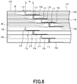
- Figure 6 shows a cross section along line AA shown in Figure 5 without hatching for convenience.
- the magnetic domain fine differentiation processed parts 19 are represented by the fine jagged lines for convenience.
- Each magnetic domain fine differentiation processed parts 19 is located on the front surface side in the drawing which is one surface of the end portion of each electromagnetic steel plate 16 constituting the yoke parts 12 and 12, and is provided within a certain range, for example, within a range of a length that is about twice the pitch p of the displacement of the joint parts 17 and 18 all over in the width direction of the electromagnetic steel plate 16. This range is defined as a range in which each magnetic flux ⁇ lies over another overlapping electromagnetic steel plate 16 on the front surface of the end portion of the electromagnetic steel plate 16.
- the magnetic domain fine differentiation processed parts 19 are formed by subjecting the portions constituting the joint parts 17 and 18 on the surface side of the electromagnetic steel plates 16 to continuous linear laser irradiation in a grid pattern in two directions orthogonal to each other. Consequently, linear marks L1 and L2 due to laser irradiation are formed on the surface of each electromagnetic steel plate 16.
- many linear marks L1 extend in the rolling direction of the electromagnetic steel plates 16 in parallel at a predetermined interval s.
- many linear marks L2 also extend in the direction orthogonal to the linear marks L1, in this case, in the direction orthogonal to the rolling direction of the electromagnetic steel plates 16 in parallel at a predetermined interval s. In this case, the interval s at which the linear marks L1 and L2 are formed is also 2.0 mm or less.
- the procedure for assembling the laminated iron core 111 will be briefly explained.
- the upper and lower yoke parts 12 and 12, the left and right leg parts 13 and 13, and the central leg part 14 are each prepared by laminating a plurality of electromagnetic steel plates 16 that have been pre-cut into a required shape and, for example, adhesion-integrating them into a block by bonding.
- the upper and lower yoke parts 12 and 12 can be the same, and the left and right leg parts 13 and 13 can also be the same.
- the upper and lower yoke parts 12 and 12 are formed by forming the magnetic domain fine differentiation processed parts 19 in advance by laser irradiation of portions constituting the joint parts 17 and 18 of the electromagnetic steel plates 16, and laminating the electromagnetic steel plates 16 provided with magnetic domain fine differentiation processed parts 19.
- the left and right leg parts 13 and 13 and the central leg part 14 which have been formed into blocks are joined, that is, step-lap joined to the lower yoke part 12 at the joint parts 17 and 18.
- a well-known method using a clamp member or a fastening member can be employed.
- windings which are not shown in the drawing, are mounted to each of the leg parts 13, 13, and 14, respectively.
- a block-shaped upper yoke part 12 is then joined, that is, step-lap joined to the upper ends of each of the leg parts 13, 13 and 14 at each of the joint parts 17 and 18.
- FIG. 5 shows the laminated iron core 11 in which the upper and lower yoke parts 12 and 12, the left and right leg parts 13 and 13, and the central leg part 41 are butt-joined.
- Figure 6 shows the cross-sectional shape of the joint parts 17 between the lower yoke part 12 and the left leg part 13 at the lower left in Figure 5 as a representative of the laminated iron core 11.
- Both end portions of the electromagnetic steel plate 16 forming the leg part 13 and the electromagnetic steel plate 16 forming the yoke parts 12 are brought into close contact with each other so that they abut one another to form joint parts 17.
- the joint parts 17 are positioned stepwise.
- the magnetic domain fine differentiation processed parts 19 on the front surface of the electromagnetic steel plates 16 located on the rear surface side of the joint parts 17 are positioned so as to be lapped with the joint parts 17.
- the laminated iron core 11 with the aforementioned configuration is provided with the joint parts 17 and 18 where the yoke parts 12 and 12 and the leg parts 13, 13, and 14 abut one another, so that at the joint parts 17 and 18, the magnetic flux ⁇ flows across the electromagnetic steel plates 16 abutting in the stacking direction. There is therefore the risk that the magnetic resistance increases at the joint parts 17 and 18 and the loss increases.
- the electromagnetic steel plates 16 constituting the yoke parts 12 and 12 are provided with the magnetic domain fine differentiation processed parts 19 in portions lapped with the joint parts 17 and 18.
- the magnetic domain fine differentiation processed parts 19 contribute to a reduction in the magnetic resistance caused by the magnetic fluxes ⁇ passing across the electromagnetic steel plates 16. As a result, the loss of the laminated iron core 11 as a whole can be made small.
- a plurality of electromagnetic steel plates 16 are laminated while the joint parts 17 and 18 where the end portions of the electromagnetic steel plates 16 abut one another are disposed in a staggered manner and magnetic domain fine differentiation processed parts 19 are provided.
- This embodiment in particular, in which the magnetic domain fine differentiation processed parts 19 are provided only in the upper and lower yoke parts 12 and 12, has a simple configuration but produces an adequate effect of reducing the loss, thereby facilitating magnetic domain fine differentiation, that is, laser irradiation.
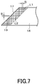
- Figure 8 shows a third embodiment and the configuration of the joint parts 32 portion of the wound iron core 31.
- This wound iron core 31 is also formed by winding a plurality of strip members 33 made of electromagnetic steel plates in the inner and outer peripheral direction while providing joint parts 32 where the end portions abut one another.
- the difference between this third embodiment and the first embodiment is that the magnetic domain fine differentiation processed parts 34 are located on both the upper and lower surfaces of the end portion of each strip member 33 and on both sides of each joint part 32 in the drawing.
- the magnetic domain fine differentiation processed parts 34 are provided with linear marks in a grid pattern by laser irradiation.
- the magnetic domain fine differentiation processed parts 34 are located in portions lapped with the joint parts 32 of the other strip members 33 on both surfaces of the end portion of each strip member 33, and provided all over in the width direction of each strip member 33 within a certain range, that is, within a range where the magnetic flux ⁇ lies across the overlapping other strip members 33.
- this third embodiment produces an advantageous effect of, for example, keeping the loss due to the magnetic resistance at the joint parts 32 small.
- the magnetic domain fine differentiation processed parts are provided by laser irradiation of the surfaces of the electromagnetic steel plates.
- magnetic domain fine differentiation processed parts may be provided by applying thermal stress by plasma irradiation or engraving with a hot iron, or by applying mechanical stress by a gear or a press.
- the linear marks in the magnetic domain fine differentiation processed parts are not necessarily provided in a grid pattern, that is, two intersecting directions, and can be formed so as to extend in various directions. They may be provided so as to be inclined obliquely with respect to the rolling direction of the electromagnetic steel plates.
- the interval s at which linear marks are formed is more preferably 0.5 mm or less.
Landscapes
- Engineering & Computer Science (AREA)
- Power Engineering (AREA)
- Manufacturing & Machinery (AREA)
- Manufacturing Cores, Coils, And Magnets (AREA)
- Soft Magnetic Materials (AREA)
- Manufacturing Of Steel Electrode Plates (AREA)
Applications Claiming Priority (2)
| Application Number | Priority Date | Filing Date | Title |
|---|---|---|---|
| JP2018233410A JP6845213B2 (ja) | 2018-12-13 | 2018-12-13 | 静止誘導機器用鉄心及び静止誘導機器 |
| PCT/JP2019/043459 WO2020121691A1 (fr) | 2018-12-13 | 2019-11-06 | Noyau de fer pour appareil à induction fixe et appareil à induction fixe |
Publications (2)
| Publication Number | Publication Date |
|---|---|
| EP3896706A1 true EP3896706A1 (fr) | 2021-10-20 |
| EP3896706A4 EP3896706A4 (fr) | 2022-09-14 |
Family
ID=71076327
Family Applications (1)
| Application Number | Title | Priority Date | Filing Date |
|---|---|---|---|
| EP19895918.1A Pending EP3896706A4 (fr) | 2018-12-13 | 2019-11-06 | Noyau de fer pour appareil à induction fixe et appareil à induction fixe |
Country Status (5)
| Country | Link |
|---|---|
| US (1) | US12142410B2 (fr) |
| EP (1) | EP3896706A4 (fr) |
| JP (1) | JP6845213B2 (fr) |
| CN (1) | CN113039621B (fr) |
| WO (1) | WO2020121691A1 (fr) |
Families Citing this family (11)
| Publication number | Priority date | Publication date | Assignee | Title |
|---|---|---|---|---|
| JP7274987B2 (ja) * | 2019-08-30 | 2023-05-17 | 東芝産業機器システム株式会社 | 巻鉄心の製造装置及び巻鉄心の製造方法 |
| JP7056717B1 (ja) * | 2020-11-13 | 2022-04-19 | Jfeスチール株式会社 | 巻鉄心 |
| CN114188134A (zh) * | 2021-11-16 | 2022-03-15 | 国网浙江省电力有限公司金华供电公司 | 一种降低铁心角部噪声的降噪结构和电力变压器 |
| JP7632411B2 (ja) * | 2022-07-21 | 2025-02-19 | Jfeスチール株式会社 | 三相三脚巻鉄心およびこれを用いた三相三脚巻鉄心変圧器 |
| JP7803293B2 (ja) * | 2023-02-02 | 2026-01-21 | Jfeスチール株式会社 | 積層鉄心、積層鉄心の製造方法及び変圧器 |
| CN117095915A (zh) * | 2023-06-26 | 2023-11-21 | 西安西电变压器有限责任公司 | 铁心、铁心结构及变压器 |
| CN121511496A (zh) | 2023-07-21 | 2026-02-10 | 杰富意钢铁株式会社 | 变压器用铁心以及变压器 |
| WO2025022804A1 (fr) | 2023-07-21 | 2025-01-30 | Jfeスチール株式会社 | Noyau de fer pour transformateur et transformateur |
| JP7622913B1 (ja) | 2023-10-27 | 2025-01-28 | Jfeスチール株式会社 | 巻鉄心及び変圧器 |
| JP7601297B1 (ja) | 2023-10-27 | 2024-12-17 | Jfeスチール株式会社 | 巻鉄心及び変圧器 |
| JP2025076669A (ja) * | 2023-11-02 | 2025-05-16 | 株式会社日立産機システム | 静止誘導機器 |
Family Cites Families (21)
| Publication number | Priority date | Publication date | Assignee | Title |
|---|---|---|---|---|
| JPS5272420A (en) * | 1975-12-12 | 1977-06-16 | Hitachi Ltd | Inner iron type transformer core |
| US4283842A (en) * | 1979-01-04 | 1981-08-18 | Westinghouse Electric Corp. | Method of making an electrical inductive apparatus |
| US4520556A (en) * | 1981-05-04 | 1985-06-04 | General Electric Company | Methods for assembling a transformer core |
| JPS5842924U (ja) * | 1981-09-17 | 1983-03-23 | 三菱電機株式会社 | 電磁誘導機器鉄心 |
| US4521957A (en) * | 1982-03-08 | 1985-06-11 | General Electric Company | Method of constructing a magnetic core |
| JPS59172220A (ja) | 1983-03-18 | 1984-09-28 | Toshiba Corp | 静止誘導電器鉄心 |
| CA1263160A (fr) * | 1984-06-15 | 1989-11-21 | Gary C. Rauch | Methodes non uniformes d'enregistrement a laser et produits obtenus |
| JPH06275433A (ja) * | 1993-03-18 | 1994-09-30 | Sony Corp | 磁性素子及びその製造方法 |
| JPH07283036A (ja) * | 1994-04-07 | 1995-10-27 | Nippon Steel Corp | 変圧器鉄芯の騒音低減方法 |
| US5959523A (en) * | 1996-10-15 | 1999-09-28 | Abb Power T&D Company Inc. | Magnetic core structure |
| US7057489B2 (en) * | 1997-08-21 | 2006-06-06 | Metglas, Inc. | Segmented transformer core |
| US7256677B2 (en) * | 2005-03-30 | 2007-08-14 | Abb Technology Ag | Transformer having a stacked core with a cruciform leg and a method of making the same |
| US7199696B2 (en) * | 2005-03-30 | 2007-04-03 | Abb Technology Ag | Transformer having a stacked core with a split leg and a method of making the same |
| KR101598831B1 (ko) * | 2009-10-14 | 2016-03-03 | 삼성전자주식회사 | 자기저항소자, 이를 포함하는 정보저장장치 및 상기 정보저장장치의 동작방법 |
| US9576709B2 (en) * | 2010-04-22 | 2017-02-21 | Abb Schweiz Ag | Transformer having a stacked core |
| JP6090553B2 (ja) * | 2011-11-24 | 2017-03-08 | Jfeスチール株式会社 | 三相変圧器用鉄心 |
| JP6215673B2 (ja) * | 2013-11-29 | 2017-10-18 | 東芝産業機器システム株式会社 | ベクトル磁気特性制御材、および、鉄心 |
| KR101562962B1 (ko) * | 2014-08-28 | 2015-10-23 | 주식회사 포스코 | 방향성 전기강판의 자구미세화 방법과 자구미세화 장치 및 이로부터 제조되는 방향성 전기강판 |
| CN106282512B (zh) * | 2015-05-11 | 2018-03-30 | 宝山钢铁股份有限公司 | 低噪音变压器用取向硅钢片制造方法 |
| JP6566351B2 (ja) * | 2015-07-08 | 2019-08-28 | 株式会社日立製作所 | 積層鉄心および静止電磁機器 |
| KR102221444B1 (ko) * | 2017-01-10 | 2021-03-02 | 닛폰세이테츠 가부시키가이샤 | 권철심, 및 그 제조 방법 |
-
2018
- 2018-12-13 JP JP2018233410A patent/JP6845213B2/ja active Active
-
2019
- 2019-11-06 WO PCT/JP2019/043459 patent/WO2020121691A1/fr not_active Ceased
- 2019-11-06 US US17/413,508 patent/US12142410B2/en active Active
- 2019-11-06 EP EP19895918.1A patent/EP3896706A4/fr active Pending
- 2019-11-06 CN CN201980075276.7A patent/CN113039621B/zh active Active
Also Published As
| Publication number | Publication date |
|---|---|
| JP6845213B2 (ja) | 2021-03-17 |
| WO2020121691A1 (fr) | 2020-06-18 |
| CN113039621A (zh) | 2021-06-25 |
| US20220051840A1 (en) | 2022-02-17 |
| US12142410B2 (en) | 2024-11-12 |
| JP2020096100A (ja) | 2020-06-18 |
| EP3896706A4 (fr) | 2022-09-14 |
| CN113039621B (zh) | 2024-09-13 |
Similar Documents
| Publication | Publication Date | Title |
|---|---|---|
| US12142410B2 (en) | Iron core for stationary induction apparatus and stationary induction apparatus | |
| EP2859564B1 (fr) | Noyau à trois étages pour transformateur non linéaire | |
| JP6937584B2 (ja) | 静止誘導電器用鉄心 | |
| US8872614B2 (en) | Transformer | |
| TWI647718B (zh) | 靜止感應裝置用鐵心 | |
| EP3841598B1 (fr) | Coeurs de transformateurs et de réacteurs présentant de nouvelles conceptions, et procédés de fabrication | |
| JPH0154843B2 (fr) | ||
| US2431155A (en) | Three-phase transformer and method of making the same | |
| JPH03147307A (ja) | 鉄心用抜板 | |
| JP6977369B2 (ja) | 変圧器の鉄心支持構造 | |
| JP7150418B2 (ja) | 巻鉄心および巻鉄心の製造方法 | |
| EP3503139B1 (fr) | Procédé et produit semi-fini de fabrication au moins un paquet-section de un composant magnétique doux | |
| JP2003217939A (ja) | 電気機器用鉄心 | |
| JP2775221B2 (ja) | 変圧器の積鉄心 | |
| JP7232133B2 (ja) | 積鉄心型静止誘導機器 | |
| JP7632200B2 (ja) | 鉄心構造及び変圧器 | |
| JP2004087668A (ja) | 鉄心及びこれを用いたコイル装置並びにこれらの製造方法 | |
| Rakhmanova et al. | Production of Plate Magnet Cores in Modern Transformers | |
| JP7430115B2 (ja) | 積鉄心静止誘導機器およびその製造方法 | |
| JPH09275022A (ja) | 磁気特性の優れた低騒音鉄心 | |
| JP2021027115A (ja) | 積鉄心静止誘導機器およびその製造方法 | |
| JPS6249609A (ja) | 静止誘導電器鉄心 | |
| JP2026010553A (ja) | 3相5脚巻鉄心 | |
| JP2000294432A (ja) | 鉄損特性および騒音特性に優れた積み鉄心型変圧器ならびにその製造方法および製造設備 | |
| JPH04116812A (ja) | ギャップ付鉄心形リアクトル |
Legal Events
| Date | Code | Title | Description |
|---|---|---|---|
| STAA | Information on the status of an ep patent application or granted ep patent |
Free format text: STATUS: THE INTERNATIONAL PUBLICATION HAS BEEN MADE |
|
| PUAI | Public reference made under article 153(3) epc to a published international application that has entered the european phase |
Free format text: ORIGINAL CODE: 0009012 |
|
| STAA | Information on the status of an ep patent application or granted ep patent |
Free format text: STATUS: REQUEST FOR EXAMINATION WAS MADE |
|
| 17P | Request for examination filed |
Effective date: 20210527 |
|
| AK | Designated contracting states |
Kind code of ref document: A1 Designated state(s): AL AT BE BG CH CY CZ DE DK EE ES FI FR GB GR HR HU IE IS IT LI LT LU LV MC MK MT NL NO PL PT RO RS SE SI SK SM TR |
|
| DAV | Request for validation of the european patent (deleted) | ||
| DAX | Request for extension of the european patent (deleted) | ||
| A4 | Supplementary search report drawn up and despatched |
Effective date: 20220812 |
|
| RIC1 | Information provided on ipc code assigned before grant |
Ipc: H01F 41/02 20060101ALI20220808BHEP Ipc: H01F 27/245 20060101AFI20220808BHEP |
|
| STAA | Information on the status of an ep patent application or granted ep patent |
Free format text: STATUS: EXAMINATION IS IN PROGRESS |
|
| 17Q | First examination report despatched |
Effective date: 20250828 |