EP3896863B1 - Nahfeldmessvorrichtung - Google Patents
Nahfeldmessvorrichtung Download PDFInfo
- Publication number
- EP3896863B1 EP3896863B1 EP21165364.7A EP21165364A EP3896863B1 EP 3896863 B1 EP3896863 B1 EP 3896863B1 EP 21165364 A EP21165364 A EP 21165364A EP 3896863 B1 EP3896863 B1 EP 3896863B1
- Authority
- EP
- European Patent Office
- Prior art keywords
- field
- antenna
- field antenna
- capacitance
- tuning circuit
- Prior art date
- Legal status (The legal status is an assumption and is not a legal conclusion. Google has not performed a legal analysis and makes no representation as to the accuracy of the status listed.)
- Active
Links
Images


Classifications
-
- H—ELECTRICITY
- H04—ELECTRIC COMMUNICATION TECHNIQUE
- H04B—TRANSMISSION
- H04B5/00—Near-field transmission systems, e.g. inductive or capacitive transmission systems
- H04B5/20—Near-field transmission systems, e.g. inductive or capacitive transmission systems characterised by the transmission technique; characterised by the transmission medium
- H04B5/22—Capacitive coupling
-
- H—ELECTRICITY
- H04—ELECTRIC COMMUNICATION TECHNIQUE
- H04B—TRANSMISSION
- H04B17/00—Monitoring; Testing
- H04B17/20—Monitoring; Testing of receivers
- H04B17/21—Monitoring; Testing of receivers for calibration; for correcting measurements
- H04B17/22—Monitoring; Testing of receivers for calibration; for correcting measurements for calibration of the receiver components
- H04B17/221—Monitoring; Testing of receivers for calibration; for correcting measurements for calibration of the receiver components of receiver antennas, e.g. as to amplitude or phase
-
- H—ELECTRICITY
- H04—ELECTRIC COMMUNICATION TECHNIQUE
- H04W—WIRELESS COMMUNICATION NETWORKS
- H04W4/00—Services specially adapted for wireless communication networks; Facilities therefor
- H04W4/80—Services using short range communication, e.g. near-field communication [NFC], radio-frequency identification [RFID] or low energy communication
-
- H—ELECTRICITY
- H01—ELECTRIC ELEMENTS
- H01Q—ANTENNAS, i.e. RADIO AERIALS
- H01Q1/00—Details of, or arrangements associated with, antennas
- H01Q1/12—Supports; Mounting means
- H01Q1/22—Supports; Mounting means by structural association with other equipment or articles
-
- H—ELECTRICITY
- H01—ELECTRIC ELEMENTS
- H01Q—ANTENNAS, i.e. RADIO AERIALS
- H01Q1/00—Details of, or arrangements associated with, antennas
- H01Q1/27—Adaptation for use in or on movable bodies
- H01Q1/273—Adaptation for carrying or wearing by persons or animals
-
- H—ELECTRICITY
- H01—ELECTRIC ELEMENTS
- H01Q—ANTENNAS, i.e. RADIO AERIALS
- H01Q7/00—Loop antennas with a substantially uniform current distribution around the loop and having a directional radiation pattern in a plane perpendicular to the plane of the loop
-
- G—PHYSICS
- G01—MEASURING; TESTING
- G01R—MEASURING ELECTRIC VARIABLES; MEASURING MAGNETIC VARIABLES
- G01R29/00—Arrangements for measuring or indicating electric quantities not covered by groups G01R19/00 - G01R27/00
- G01R29/08—Measuring electromagnetic field characteristics
- G01R29/0864—Measuring electromagnetic field characteristics characterised by constructional or functional features
- G01R29/0878—Sensors; antennas; probes; detectors
Definitions
- the present specification relates to systems, methods, apparatuses, devices, articles of manufacture and instructions for near-field measurement.
- a near-field measuring device comprising: a near-field antenna; a tuning circuit galvanically coupled to the near-field antenna and configured to set a resonant frequency and/or a quality factor of the measuring device; and a current sensor inductively coupled to the near-field antenna and configured to generate a signal in response to a current flowing through the galvanic coupling between the near-field antenna and the tuning circuit; wherein the signal represents a measurement of non-propagating quasi-static near-field signals received by the near-field antenna.
- the current sensor is a transformer or a toroidal coil.
- the current sensor is configured to amplify the current flowing in the galvanic coupling.
- the tuning circuit includes a capacitance and a resistance.
- the near-field antenna includes a set of conductive surfaces configured to be responsive to an electric near-field signal; the conductive surfaces together form a capacitance; the tuning circuit capacitance is larger than the conductive surfaces capacitance such that a larger portion of the current flowing through near-field antenna flows through the tuning circuit capacitance; and the current sensor is inductively coupled in series with the tuning circuit capacitance and coupled in parallel with the tuning circuit resistance.
- the current sensor includes a primary winding and a secondary winding; wherein the primary winding is galvanically coupled to the near-field antenna; and wherein the secondary winding is inductively coupled to the primary winding, and galvanically coupled to the sensing element.
- the sensing element includes a resistance; the signal is a voltage; and the resistance is configured to generate the voltage in response to the current flowing through the primary winding.
- the sensing element includes a low noise amplifier; the signal is a voltage; and the low noise amplifier is configured to generate an amplified output signal in response to the current flowing through the primary winding.
- the sensing element is configured to be coupled to a measurement instrument; and the measurement instrument is configured to output either a magnetic near-field strength signal and/or an electric near-field strength signal in response to the current flowing through the primary winding.
- the sensing element is configured to be coupled to a baseband communications circuit; and the communications circuit is configured to output a communications signal in response to the current flowing through the primary winding.
- the tuning circuit includes a variable tuning capacitance bank configured to set a resonant frequency of the near-field antenna in response to a control line.
- the tuning circuit includes a variable tuning resistance bank configured to set a quality factor or bandwidth of the near-field antenna in response to a control line.
- the tuning circuit includes a fixed tuning capacitance configured to set a fixed resonant frequency of the near-field antenna and a fixed tuning resistance configured to set a fixed quality factor or bandwidth of the near-field antenna.
- the current flowing in the galvanic coupling between the near-field antenna and the tuning circuit is generated only by the non-propagating quasi-static near-field signals received by the near-field antenna.
- the near-field antenna is a near-field magnetic antenna responsive to non-propagating quasi-static near-field magnetic signals.
- the near-field antenna is a near-field electric antenna responsive to non-propagating quasi-static near-field electric signals.
- the near-field antenna is a near-field electromagnetic antenna responsive to non-propagating quasi-static near-field electric and magnetic signals.
- the near-field measuring device is configured to be capacitively coupled to an external conductive surface from which the measurement of non-propagating quasi-static near-field signals is to be made.
- the near-field measuring device is embedded in at least one of: a wearable device; a smart watch; a smartwatch housing, an earbud, a hearing aid, a medical device, an activity tracker, or a heart rate monitor.
- near-field interactions between a near-field device perhaps on a user's body, and other conductive surfaces and/or other wireless networked devices (e.g. Internet of Things (IoT) devices, wearables, earbuds, body area networks, gaming products and medical products like continuous glucose monitoring, etc.) based on near-field electromagnetic induction (NFEMI), where the transmitter and receiver are coupled by both magnetic (H) and electric (E) fields.
- IoT Internet of Things
- E electric
- An H-field antenna i.e. magnetic antenna
- Any E-field component from an H-field antenna is strongly reduced (e.g. -20 to -60 dB reduction, a factor of 0.1 to 0.0008 (10% to 0.08%) depending on the antenna design).
- a small loop antenna is an example H-field antenna and includes a loop antenna with dimensions much smaller than the wavelength of its use.
- the small loop antenna does not resonate at the NFEMI carrier frequency but is instead tuned to resonance by an external reactance.
- the current in the small loop antenna has in every position of the loop the same value.
- An E-field antenna i.e. electric antenna
- Any H-field component from an E-field antenna is strongly reduced (e.g. -20 to -60 dB reduction, a factor of 0.1 to 0.0008 (10% to 0.08%) depending on the antenna design).
- a short loaded dipole antenna is an example E-field antenna and includes a short dipole with dimensions much smaller than the NFEMI carrier frequency and in some example embodiments has extra capacitance surfaces at both ends.
- Some wearables such as hearing aids and wireless earbuds, employ Near-Field Magnetic Induction (NFMI) as a wireless communication method.
- NFMI wireless communication two loosely coupled coils realize signal transfer. No radiation of radio waves takes place. A current flowing in the transmission coil generates a H-field which in turn induces a current in the receiving coil. In this way, wireless communication is accomplished.
- H-field based NFMI systems with small antenna coils have a limited range that may be much smaller than an entire wearable user's body.
- Such H-field communications are sensitive to coil orientation.
- a H-field induction based system cannot cover an entire human body. However, since in hearing aids both coils are always aligned with each other, they are not influenced by the movement of the human body.
- NFEI Near-field Electric Induction
- BCC Body Coupled Communication
- E-field based NFEI signals can have a greater range than H-field based NFMI signals, the E-field signal strength can vary with regard to body posture and is sensitive to body movements. The body can even partially block a capacitive return path, thereby increasing E-field channel loss and reliable and robust wireless communication is not possible.
- example embodiments of a near-field measuring device tailored to measuring these concentrated, low level near-field signals near conductive body surfaces and/or in surrounding environments. These example embodiments are capable of measuring electromagnetic field strengths as low as 10mV/m. Once captured, these near-field signals can then be recorded and characterized by additional diagnostic devices such as a frequency spectrum analyzers or oscilloscopes.
- Figure 1 is an example near-field antenna 100.
- the antenna 100 includes a coil (H-field) antenna 105 for magnetic fields, in conjunction with a short loaded dipole (E-field) antenna 120 for electric fields.
- the H-field antenna 105 includes a ferrite core 110 wound with wire 115.
- the E-field antenna 120 includes two conductive loading structures 125 and 130.
- Antenna 100 feed points 135, 140 are coupled to various tuning, measurement, and/or transceiver circuitry, such as downstream resonance frequency and bandwidth tuning banks, current sensors, and radio transmitter and receiver integrated circuit (RF-IC).
- RF-IC radio transmitter and receiver integrated circuit
- the magnetic and electric fields that are substantially confined to the structure and not significantly radiate in free-space can in some example embodiments be measured with much greater sensitivity.
- the antenna 100 operates at or below 50 MHz (e.g. for example at 30 MHz) to ensure that the fields are following the structure's contours and to ensure that far field radiation is strongly reduced.
- the near-field antenna 100 shown is an NFEMI antenna
- just the coil (H-field) antenna 105 or the short loaded dipole (E-field) antenna 120 could be separately used if only magnetic (H) fields or electric (E) fields are to be respectively sensed and measured.
- Figure 2 is an example of a first near-field measurement device 200.
- the first near-field measuring device 200 includes the near-field antenna 100, supporting circuits 202, and configured to receive non-propagating quasi-static near-field signals.
- the near-field measuring device 200 is configured to receive and measure a non-propagating quasi-static near-field signal.
- the near-field antenna 100 may in some example embodiments also be coupled to a transmitter circuit (not shown) for two-way communications.
- the example idealized antenna 100 includes the magnetic (H-field) antenna 105 having a resistance (R3) and an inductance (LI), the electric (E-field) antenna 120 having a conductive structure formed from the two loading plates 125 and 130 and a resistance (R4), and the two feeding points 135, 140.
- the supporting circuits 202 include a tuning circuit 204, a current sensor 206, and a controller 216.
- the tuning circuit 204 is coupled to the first and second feed points 135, 140.
- the tuning circuit 204 includes a first variable tuning capacitance bank (C1), a second variable tuning capacitance bank (C2), a first variable tuning resistance bank (R1), and a second variable tuning resistance bank (R2).
- the capacitance banks and resistance banks are coupled to a ground 224.
- the capacitive banks are coupled to the controller 216 by control line 218, and the resistance banks are coupled to the controller 216 by control line 220.
- the controller 216 adjusts the first and second capacitance banks (C1), (C2) to adjust a resonant frequency of the magnetic 105 and the electric 120 antennas (e.g. to 10.6 MHz).
- the controller 216 adjusts the first and second resistance banks (R1), (R2) to adjust a bandwidth of the magnetic 105 and the electric 120 antennas (e.g. to 400 KHz) sufficient to allow the non-propagating quasi-static near-field signal to be received from the antennas 105, 120.
- the capacitance banks (C1), (C2) are equally tuned using the control line 218 from the controller 216, and the resistance banks (R1), (R2) are equally tuned using the control line 220 from the controller 216.
- the current sensor 206 includes a primary winding 208 galvanically coupled to the near-field antenna 100 and the tuning circuit 204.
- the current sensor 206 also includes a secondary winding 210 inductively coupled to the primary winding 208 via an optional ferrite core 212 and to a sensing element 214 (e.g. resistor).
- the current sensor 206 in some example embodiments is a transformer or toroidal coil.
- the current sensor 206 inductively couples the near-field antenna 100 to the sensing element 214 to help reduce current draw, enable greater sensitivity, and minimize loading of the near-field antenna 100 for improved near-field sensitivity.
- the inductively sensed resonant current is converted to a voltage across the sensing element 214 for further instrument capture and analysis.
- the controller 216 is then coupled to receive a signal (e.g. voltage) from the sensing element 214 by a measure line 222.
- a signal e.g. voltage
- the signal generated across the sensing element 214 can be measured by the controller 216.
- the voltage generated can in some example embodiments be used as frontend for a baseband receiver in a body communication device.
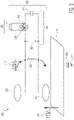
- Figure 3 is an example application 300 of a second near-field measurement device 302.
- This second near-field measurement device 302 used in this example application 300 is a modified version of the first near-field measuring device 200.
- the coil (H-field) antenna 105, conductive surfaces 125, 130 and the current sensor 206 are the same as for the first near-field measuring device 200; however, the second near-field measurement device 302 includes different tuning circuit 304 that instead includes a fixed tuning capacitance 306 and a fixed tuning resistance 308.
- tuning capacitor 306 may be 60 pF and the tuning resistance 308 may be 12 kOhm.
- the second near-field measurement device 302 is positioned close to a conductive structure 310 (e.g. a human body).
- the conductive structure 310 forms a capacitance 312 (e.g. 100 pF) with the ground 224.
- Conductive surface 130 is positioned close to the conductive structure 310 and located at the position where the electric and/or the magnetic fields are to be measured.
- Conductive surface 125 is positioned further away from the conductive structure 310 compared with the conductive surface 130. Both conductive surfaces 125, 130 together form their own capacitance. The capacitance value is depending on the dimensions but practical values can be in the order of 5 pF.
- both conductive surfaces 125, 130 are in the presence of an electric (E-field) 316, a voltage is induced between them and since the conductive surface 130 is close to the conductive structure 310 the electric (E-field) 316 present on the conductive structure 310 will induce a voltage between both surfaces 125, 130.
- the near-field measuring device's 302 tuning capacitance 306 is much larger than the capacitance between the conductive surfaces 125, 130. In such embodiments, a large part of the second near-field measurement device's 302 resonance current flows through the tuning capacitance 306 and thus the primary winding 208 portion of the current sensor 206 is positioned between the tuning capacitance 306 and the tuning resistance 308 as shown in Figure 3 .
- the controller 212 is not shown in this figure but would be coupled to the sensing element 214 of the current sensor 206 as discussed in Figure 2 .
- Figure 4 is an example application 400 of a third near-field measurement device 402.
- the third near-field measurement device 402 is similar to the second near-field measurement device 302, however a different current sensor 404 is included.
- the current sensor 404 includes the primary winding 208, the secondary winding 210, and an optional ferrite core 212; however a new sensing element 406 is included.
- the sensing element 406 includes a first LNA 408, a filter 410, a second LNA 412, and an output 414.
- the first LNA 408 is connected to the secondary winding 210 and converts the secondary winding 210 current into an amplified voltage. This amplified voltage can be directly coupled to a measurement instrument or baseband communications circuit for further processing.
- the second LNA 412 may be used to provide sufficient output voltage so that the measurement instrument or baseband communications circuit has sufficient signal strength.
- the output 414 may be connected to the measurement instrument or baseband communications circuit with a coaxial cable.
- the measurement instrument or baseband communications circuit can be capacitively coupled to ground 224 via their mains power supply.
- Grounding 224 of the mains power supply enables more accurate sensing of the electric fields such that the measurement instrument or baseband communications circuit do not themselves become part of the antennas and thereby overestimate the measured currents.
- these near-field measurement devices 200, 302, 402 include: monitoring a quality of on-body links, use as a new frontend for applications with industrial interference, as a measuring device for Human Exposure to wireless body area devices, or for regular near-field (e.g. NFEMI, NFEI, NFMI, etc.) communications.
- regular near-field e.g. NFEMI, NFEI, NFMI, etc.
- a near-field measuring device including: a near-field antenna; a tuning circuit galvanically coupled to the near-field antenna and configured to set a resonant frequency and/or a quality factor of the measuring device; and a current sensor inductively coupled to the near-field antenna and configured to generate a signal in response to a current flowing through the galvanic coupling between the near-field antenna and the tuning circuit; wherein the signal represents a measurement of non-propagating quasi-static near-field signals received by the near-field antenna.
- these instructions/steps are implemented as functional and software instructions.
- the instructions can be implemented either using logic gates, application specific chips, firmware, as well as other hardware forms.
- the instructions are embodied as a set of executable instructions in a non-transitory computer-readable or computer-usable media which are effected on a computer or machine programmed with and controlled by said executable instructions.
- Said instructions are loaded for execution on a processor (such as one or more CPUs).
- Said processor includes microprocessors, microcontrollers, processor modules or subsystems (including one or more microprocessors or microcontrollers), or other control or computing devices.
- a processor can refer to a single component or to plural components.
- Said computer-readable or computer-usable storage medium or media is (are) considered to be part of an article (or article of manufacture).
- An article or article of manufacture can refer to any manufactured single component or multiple components.
- the non-transitory machine or computer-usable media or mediums as defined herein excludes signals, but such media or mediums may be capable of receiving and processing information from signals and/or other transitory mediums.
Landscapes
- Engineering & Computer Science (AREA)
- Computer Networks & Wireless Communication (AREA)
- Signal Processing (AREA)
- Physics & Mathematics (AREA)
- Electromagnetism (AREA)
- Near-Field Transmission Systems (AREA)
Claims (15)
- Nahfeldmessvorrichtung, umfassend:eine Nahfeldantenne (100)eine Abstimmschaltung (204), die galvanisch mit der Nahfeldantenne gekoppelt ist und dazu eingerichtet ist, eine Resonanzfrequenz und/oder einen Gütefaktor der Messvorrichtung einzustellen; gekennzeichnet durcheinen Stromsensor (206), der induktiv mit der Nahfeldantenne gekoppelt ist und dazu eingerichtet ist, ein Signal als Reaktion auf einen Strom zu erzeugen, der durch die galvanische Kopplung zwischen der Nahfeldantenne und der Abstimmschaltung fließt;wobei das Signal eine Messung von nicht propagierenden quasistatischen Nahfeldsignalen darstellt, die von der Nahfeldantenne empfangen werden.
- Vorrichtung nach Anspruch 1:
wobei der Stromsensor ein Transformator oder eine Ringspule ist. - Vorrichtung nach Anspruch 1 oder 2:
wobei der Stromsensor dazu eingerichtet ist, den in der galvanischen Kopplung fließenden Strom zu verstärken. - Vorrichtung nach einem der vorhergehenden Ansprüche:
wobei die Abstimmschaltung eine Kapazität und einen Widerstand aufweist. - Vorrichtung nach Anspruch 4:wobei die Nahfeldantenne einen Satz von leitenden Oberflächen aufweist, die dazu eingerichtet sind, auf ein elektrisches Nahfeldsignal anzusprechen;wobei die leitenden Oberflächen zusammen eine Kapazität bilden;wobei die Kapazität der Abstimmschaltung größer ist als die Kapazität der leitenden Oberflächen ist, so dass ein größerer Teil des Stroms, der durch die Nahfeldantenne fließt, durch die Kapazität der Abstimmschaltung fließt; undwobei der Stromsensor induktiv in Reihe mit der Kapazität der Abstimmschaltung gekoppelt ist und parallel mit dem Widerstand der Abstimmschaltung gekoppelt ist.
- Vorrichtung nach einem der vorhergehenden Ansprüche:ferner umfassend ein Sensorelement;wobei der Stromsensor eine Primärwicklung und eine Sekundärwicklung aufweist;wobei die Primärwicklung galvanisch mit der Nahfeldantenne gekoppelt ist; undwobei die Sekundärwicklung induktiv mit der Primärwicklung gekoppelt ist und galvanisch mit dem Sensorelement gekoppelt ist.
- Vorrichtung nach Anspruch 6:wobei das Sensorelement einen Widerstand aufweist;wobei das Signal eine Spannung ist; undwobei der Widerstand dazu eingerichtet ist, die Spannung als Reaktion auf den durch die Primärwicklung fließenden Strom zu erzeugen.
- Vorrichtung nach Anspruch 6 oder 7:wobei das Sensorelement einen rauscharmen Verstärker aufweist;wobei das Signal eine Spannung ist; undwobei der rauscharme Verstärker dazu eingerichtet ist, als Reaktion auf den durch die Primärwicklung fließenden Strom ein verstärktes Ausgangssignal zu erzeugen.
- Vorrichtung nach einem der Ansprüche 6 bis 8:wobei das Sensorelement dazu eingerichtet ist, mit einem Messinstrument gekoppelt zu werden; undwobei das Messinstrument dazu eingerichtet ist, entweder ein magnetisches Nahfeldstärkensignal und/oder ein elektrisches Nahfeldstärkensignal als Reaktion auf den durch die Primärwicklung fließenden Strom auszugeben.
- Vorrichtung nach einem der Ansprüche 6 bis 9:wobei das Sensorelement dazu eingerichtet ist, mit einer Basisband-Kommunikationsschaltung gekoppelt zu werden; undwobei die Kommunikationsschaltung dazu eingerichtet ist, ein Kommunikationssignal als Reaktion auf den durch die Primärwicklung fließenden Strom auszugeben.
- Vorrichtung nach einem der vorhergehenden Ansprüche:
wobei die Abstimmschaltung eine Bank mit variablem Abstimmwiderstand aufweist, die dazu eingerichtet ist, eine Resonanzfrequenz der Nahfeldantenne als Reaktion auf eine Steuerleitung einzustellen. - Vorrichtung nach einem der vorhergehenden Ansprüche:
wobei die Abstimmschaltung eine Bank mit variablem Abstimmwiderstand aufweist, die dazu eingerichtet ist, einen Gütefaktor oder eine Bandbreite der Nahfeldantenne als Reaktion auf eine Steuerleitung einzustellen. - Vorrichtung nach einem der vorhergehenden Ansprüche:
wobei die Abstimmschaltung eine feste Abstimmkapazität aufweist, die dazu eingerichtet ist, eine feste Resonanzfrequenz der Nahfeldantenne einzustellen, und einen festen Abstimmwiderstand, der dazu eingerichtet ist, einen festen Gütefaktor oder eine feste Bandbreite der Nahfeldantenne einzustellen. - Vorrichtung nach einem der vorhergehenden Ansprüche:
wobei der in der galvanischen Kopplung zwischen der Nahfeldantenne und der Abstimmschaltung fließende Strom nur durch die nicht propagierenden quasistatischen Nahfeldsignale, die durch die Nahfeldantenne empfangen werden, erzeugt wird. - Vorrichtung nach einem der vorhergehenden Ansprüche:
wobei die Nahfeldantenne eine magnetische Nahfeldantenne ist, die auf nicht propagierende quasistatische magnetische Nahfeldsignale anspricht.
Applications Claiming Priority (1)
| Application Number | Priority Date | Filing Date | Title |
|---|---|---|---|
| US16/840,495 US10826627B1 (en) | 2020-04-06 | 2020-04-06 | Near-field measuring device |
Publications (2)
| Publication Number | Publication Date |
|---|---|
| EP3896863A1 EP3896863A1 (de) | 2021-10-20 |
| EP3896863B1 true EP3896863B1 (de) | 2022-12-28 |
Family
ID=73019787
Family Applications (1)
| Application Number | Title | Priority Date | Filing Date |
|---|---|---|---|
| EP21165364.7A Active EP3896863B1 (de) | 2020-04-06 | 2021-03-26 | Nahfeldmessvorrichtung |
Country Status (3)
| Country | Link |
|---|---|
| US (1) | US10826627B1 (de) |
| EP (1) | EP3896863B1 (de) |
| CN (1) | CN113498048B (de) |
Families Citing this family (1)
| Publication number | Priority date | Publication date | Assignee | Title |
|---|---|---|---|---|
| US11677151B2 (en) * | 2020-09-11 | 2023-06-13 | Nxp B.V. | Near-field communications device |
Family Cites Families (9)
| Publication number | Priority date | Publication date | Assignee | Title |
|---|---|---|---|---|
| US20070218837A1 (en) * | 2006-03-14 | 2007-09-20 | Sony Ericsson Mobile Communications Ab | Data communication in an electronic device |
| CN101861703B (zh) * | 2007-11-19 | 2013-08-28 | Nxp股份有限公司 | 用于无接触通信的收发电路 |
| US8274386B1 (en) | 2009-03-23 | 2012-09-25 | The United States Of America As Represented By The Secretary Of The Navy | Human presence electric field sensor |
| FR2945137B1 (fr) * | 2009-04-30 | 2011-06-24 | Pascal Metivier | Systeme de programmation d'une serrure comportant des moyens de communication sans contact de type nfc |
| WO2017035143A1 (en) * | 2015-08-24 | 2017-03-02 | The Regents Of The University Of California | Low power magnetic field body area network |
| US10277267B1 (en) * | 2018-02-21 | 2019-04-30 | Nxp B.V. | Antenna tuning device |
| US10978791B2 (en) * | 2018-05-07 | 2021-04-13 | Nxp B.V. | Combination antenna |
| US10277284B1 (en) * | 2018-11-20 | 2019-04-30 | Nxp B.V. | Near-field device |
| US10491270B1 (en) * | 2018-11-26 | 2019-11-26 | Nxp B.V. | Near-field device |
-
2020
- 2020-04-06 US US16/840,495 patent/US10826627B1/en active Active
-
2021
- 2021-03-26 EP EP21165364.7A patent/EP3896863B1/de active Active
- 2021-04-06 CN CN202110369902.2A patent/CN113498048B/zh active Active
Also Published As
| Publication number | Publication date |
|---|---|
| EP3896863A1 (de) | 2021-10-20 |
| CN113498048B (zh) | 2026-01-23 |
| CN113498048A (zh) | 2021-10-12 |
| US10826627B1 (en) | 2020-11-03 |
Similar Documents
| Publication | Publication Date | Title |
|---|---|---|
| EP3367503B1 (de) | Elektromagnetische nahfeld-induktionsantenne (nfem) | |
| EP3917022B1 (de) | Drahtlose nahfeldvorrichtung | |
| EP3355481A1 (de) | Vorrichtung zur elektromagnetischen nahfeldinduktion (nfemi) | |
| EP3389135B1 (de) | Elektromagnetische nahfeld-induktionsantenne (nfem) | |
| EP3687077A1 (de) | Nahfeldkommunikationsvorrichtung | |
| EP3910803B1 (de) | Drahtlose nahfeldvorrichtung | |
| EP3866345B1 (de) | Elektromagnetische nahfeld-induktionsantenne (nfem) | |
| US10862542B1 (en) | Near-field converter | |
| EP3691135A1 (de) | Nahfeldkommunikationsvorrichtung | |
| EP3930206A1 (de) | Nahfeldkommunikationsvorrichtung | |
| EP3787192B1 (de) | Qualitätsfaktorkontrolle für eine drahtlose nahfeldvorrichtung | |
| EP3896863B1 (de) | Nahfeldmessvorrichtung | |
| US10763921B1 (en) | Near-field electromagnetic induction device | |
| EP3934116B1 (de) | Nahfeldkommunikationsvorrichtung | |
| US11368193B2 (en) | Near-field electromagnetic induction (NFEMI) antenna | |
| CN112543042B (zh) | 近场装置 | |
| EP3553959B1 (de) | Drahtlose vorrichtung | |
| US20220095239A1 (en) | Near-field communication device with variable path-loss |
Legal Events
| Date | Code | Title | Description |
|---|---|---|---|
| PUAI | Public reference made under article 153(3) epc to a published international application that has entered the european phase |
Free format text: ORIGINAL CODE: 0009012 |
|
| STAA | Information on the status of an ep patent application or granted ep patent |
Free format text: STATUS: THE APPLICATION HAS BEEN PUBLISHED |
|
| AK | Designated contracting states |
Kind code of ref document: A1 Designated state(s): AL AT BE BG CH CY CZ DE DK EE ES FI FR GB GR HR HU IE IS IT LI LT LU LV MC MK MT NL NO PL PT RO RS SE SI SK SM TR |
|
| B565 | Issuance of search results under rule 164(2) epc |
Effective date: 20210922 |
|
| STAA | Information on the status of an ep patent application or granted ep patent |
Free format text: STATUS: REQUEST FOR EXAMINATION WAS MADE |
|
| 17P | Request for examination filed |
Effective date: 20220420 |
|
| RBV | Designated contracting states (corrected) |
Designated state(s): AL AT BE BG CH CY CZ DE DK EE ES FI FR GB GR HR HU IE IS IT LI LT LU LV MC MK MT NL NO PL PT RO RS SE SI SK SM TR |
|
| RIC1 | Information provided on ipc code assigned before grant |
Ipc: G01R 29/08 20060101ALI20220722BHEP Ipc: H04B 5/00 20060101AFI20220722BHEP |
|
| GRAP | Despatch of communication of intention to grant a patent |
Free format text: ORIGINAL CODE: EPIDOSNIGR1 |
|
| STAA | Information on the status of an ep patent application or granted ep patent |
Free format text: STATUS: GRANT OF PATENT IS INTENDED |
|
| INTG | Intention to grant announced |
Effective date: 20220920 |
|
| GRAS | Grant fee paid |
Free format text: ORIGINAL CODE: EPIDOSNIGR3 |
|
| GRAA | (expected) grant |
Free format text: ORIGINAL CODE: 0009210 |
|
| STAA | Information on the status of an ep patent application or granted ep patent |
Free format text: STATUS: THE PATENT HAS BEEN GRANTED |
|
| AK | Designated contracting states |
Kind code of ref document: B1 Designated state(s): AL AT BE BG CH CY CZ DE DK EE ES FI FR GB GR HR HU IE IS IT LI LT LU LV MC MK MT NL NO PL PT RO RS SE SI SK SM TR |
|
| REG | Reference to a national code |
Ref country code: GB Ref legal event code: FG4D |
|
| REG | Reference to a national code |
Ref country code: CH Ref legal event code: EP |
|
| REG | Reference to a national code |
Ref country code: DE Ref legal event code: R096 Ref document number: 602021001072 Country of ref document: DE |
|
| REG | Reference to a national code |
Ref country code: AT Ref legal event code: REF Ref document number: 1541117 Country of ref document: AT Kind code of ref document: T Effective date: 20230115 |
|
| REG | Reference to a national code |
Ref country code: IE Ref legal event code: FG4D |
|
| REG | Reference to a national code |
Ref country code: LT Ref legal event code: MG9D |
|
| PG25 | Lapsed in a contracting state [announced via postgrant information from national office to epo] |
Ref country code: SE Free format text: LAPSE BECAUSE OF FAILURE TO SUBMIT A TRANSLATION OF THE DESCRIPTION OR TO PAY THE FEE WITHIN THE PRESCRIBED TIME-LIMIT Effective date: 20221228 Ref country code: NO Free format text: LAPSE BECAUSE OF FAILURE TO SUBMIT A TRANSLATION OF THE DESCRIPTION OR TO PAY THE FEE WITHIN THE PRESCRIBED TIME-LIMIT Effective date: 20230328 Ref country code: LT Free format text: LAPSE BECAUSE OF FAILURE TO SUBMIT A TRANSLATION OF THE DESCRIPTION OR TO PAY THE FEE WITHIN THE PRESCRIBED TIME-LIMIT Effective date: 20221228 Ref country code: FI Free format text: LAPSE BECAUSE OF FAILURE TO SUBMIT A TRANSLATION OF THE DESCRIPTION OR TO PAY THE FEE WITHIN THE PRESCRIBED TIME-LIMIT Effective date: 20221228 |
|
| REG | Reference to a national code |
Ref country code: NL Ref legal event code: MP Effective date: 20221228 |
|
| REG | Reference to a national code |
Ref country code: AT Ref legal event code: MK05 Ref document number: 1541117 Country of ref document: AT Kind code of ref document: T Effective date: 20221228 |
|
| PG25 | Lapsed in a contracting state [announced via postgrant information from national office to epo] |
Ref country code: RS Free format text: LAPSE BECAUSE OF FAILURE TO SUBMIT A TRANSLATION OF THE DESCRIPTION OR TO PAY THE FEE WITHIN THE PRESCRIBED TIME-LIMIT Effective date: 20221228 Ref country code: LV Free format text: LAPSE BECAUSE OF FAILURE TO SUBMIT A TRANSLATION OF THE DESCRIPTION OR TO PAY THE FEE WITHIN THE PRESCRIBED TIME-LIMIT Effective date: 20221228 Ref country code: HR Free format text: LAPSE BECAUSE OF FAILURE TO SUBMIT A TRANSLATION OF THE DESCRIPTION OR TO PAY THE FEE WITHIN THE PRESCRIBED TIME-LIMIT Effective date: 20221228 Ref country code: GR Free format text: LAPSE BECAUSE OF FAILURE TO SUBMIT A TRANSLATION OF THE DESCRIPTION OR TO PAY THE FEE WITHIN THE PRESCRIBED TIME-LIMIT Effective date: 20230329 |
|
| PG25 | Lapsed in a contracting state [announced via postgrant information from national office to epo] |
Ref country code: NL Free format text: LAPSE BECAUSE OF FAILURE TO SUBMIT A TRANSLATION OF THE DESCRIPTION OR TO PAY THE FEE WITHIN THE PRESCRIBED TIME-LIMIT Effective date: 20221228 |
|
| PG25 | Lapsed in a contracting state [announced via postgrant information from national office to epo] |
Ref country code: SM Free format text: LAPSE BECAUSE OF FAILURE TO SUBMIT A TRANSLATION OF THE DESCRIPTION OR TO PAY THE FEE WITHIN THE PRESCRIBED TIME-LIMIT Effective date: 20221228 Ref country code: RO Free format text: LAPSE BECAUSE OF FAILURE TO SUBMIT A TRANSLATION OF THE DESCRIPTION OR TO PAY THE FEE WITHIN THE PRESCRIBED TIME-LIMIT Effective date: 20221228 Ref country code: PT Free format text: LAPSE BECAUSE OF FAILURE TO SUBMIT A TRANSLATION OF THE DESCRIPTION OR TO PAY THE FEE WITHIN THE PRESCRIBED TIME-LIMIT Effective date: 20230428 Ref country code: ES Free format text: LAPSE BECAUSE OF FAILURE TO SUBMIT A TRANSLATION OF THE DESCRIPTION OR TO PAY THE FEE WITHIN THE PRESCRIBED TIME-LIMIT Effective date: 20221228 Ref country code: EE Free format text: LAPSE BECAUSE OF FAILURE TO SUBMIT A TRANSLATION OF THE DESCRIPTION OR TO PAY THE FEE WITHIN THE PRESCRIBED TIME-LIMIT Effective date: 20221228 Ref country code: CZ Free format text: LAPSE BECAUSE OF FAILURE TO SUBMIT A TRANSLATION OF THE DESCRIPTION OR TO PAY THE FEE WITHIN THE PRESCRIBED TIME-LIMIT Effective date: 20221228 Ref country code: AT Free format text: LAPSE BECAUSE OF FAILURE TO SUBMIT A TRANSLATION OF THE DESCRIPTION OR TO PAY THE FEE WITHIN THE PRESCRIBED TIME-LIMIT Effective date: 20221228 |
|
| P01 | Opt-out of the competence of the unified patent court (upc) registered |
Effective date: 20230725 |
|
| PG25 | Lapsed in a contracting state [announced via postgrant information from national office to epo] |
Ref country code: SK Free format text: LAPSE BECAUSE OF FAILURE TO SUBMIT A TRANSLATION OF THE DESCRIPTION OR TO PAY THE FEE WITHIN THE PRESCRIBED TIME-LIMIT Effective date: 20221228 Ref country code: PL Free format text: LAPSE BECAUSE OF FAILURE TO SUBMIT A TRANSLATION OF THE DESCRIPTION OR TO PAY THE FEE WITHIN THE PRESCRIBED TIME-LIMIT Effective date: 20221228 Ref country code: IS Free format text: LAPSE BECAUSE OF FAILURE TO SUBMIT A TRANSLATION OF THE DESCRIPTION OR TO PAY THE FEE WITHIN THE PRESCRIBED TIME-LIMIT Effective date: 20230428 Ref country code: AL Free format text: LAPSE BECAUSE OF FAILURE TO SUBMIT A TRANSLATION OF THE DESCRIPTION OR TO PAY THE FEE WITHIN THE PRESCRIBED TIME-LIMIT Effective date: 20221228 |
|
| REG | Reference to a national code |
Ref country code: DE Ref legal event code: R097 Ref document number: 602021001072 Country of ref document: DE |
|
| PG25 | Lapsed in a contracting state [announced via postgrant information from national office to epo] |
Ref country code: MC Free format text: LAPSE BECAUSE OF FAILURE TO SUBMIT A TRANSLATION OF THE DESCRIPTION OR TO PAY THE FEE WITHIN THE PRESCRIBED TIME-LIMIT Effective date: 20221228 Ref country code: DK Free format text: LAPSE BECAUSE OF FAILURE TO SUBMIT A TRANSLATION OF THE DESCRIPTION OR TO PAY THE FEE WITHIN THE PRESCRIBED TIME-LIMIT Effective date: 20221228 |
|
| PLBE | No opposition filed within time limit |
Free format text: ORIGINAL CODE: 0009261 |
|
| STAA | Information on the status of an ep patent application or granted ep patent |
Free format text: STATUS: NO OPPOSITION FILED WITHIN TIME LIMIT |
|
| REG | Reference to a national code |
Ref country code: BE Ref legal event code: MM Effective date: 20230331 |
|
| 26N | No opposition filed |
Effective date: 20230929 |
|
| PG25 | Lapsed in a contracting state [announced via postgrant information from national office to epo] |
Ref country code: LU Free format text: LAPSE BECAUSE OF NON-PAYMENT OF DUE FEES Effective date: 20230326 |
|
| REG | Reference to a national code |
Ref country code: IE Ref legal event code: MM4A |
|
| PG25 | Lapsed in a contracting state [announced via postgrant information from national office to epo] |
Ref country code: SI Free format text: LAPSE BECAUSE OF FAILURE TO SUBMIT A TRANSLATION OF THE DESCRIPTION OR TO PAY THE FEE WITHIN THE PRESCRIBED TIME-LIMIT Effective date: 20221228 Ref country code: IE Free format text: LAPSE BECAUSE OF NON-PAYMENT OF DUE FEES Effective date: 20230326 |
|
| PG25 | Lapsed in a contracting state [announced via postgrant information from national office to epo] |
Ref country code: BE Free format text: LAPSE BECAUSE OF NON-PAYMENT OF DUE FEES Effective date: 20230331 |
|
| PG25 | Lapsed in a contracting state [announced via postgrant information from national office to epo] |
Ref country code: IT Free format text: LAPSE BECAUSE OF FAILURE TO SUBMIT A TRANSLATION OF THE DESCRIPTION OR TO PAY THE FEE WITHIN THE PRESCRIBED TIME-LIMIT Effective date: 20221228 |
|
| REG | Reference to a national code |
Ref country code: CH Ref legal event code: PL |
|
| PG25 | Lapsed in a contracting state [announced via postgrant information from national office to epo] |
Ref country code: BG Free format text: LAPSE BECAUSE OF FAILURE TO SUBMIT A TRANSLATION OF THE DESCRIPTION OR TO PAY THE FEE WITHIN THE PRESCRIBED TIME-LIMIT Effective date: 20221228 |
|
| PG25 | Lapsed in a contracting state [announced via postgrant information from national office to epo] |
Ref country code: BG Free format text: LAPSE BECAUSE OF FAILURE TO SUBMIT A TRANSLATION OF THE DESCRIPTION OR TO PAY THE FEE WITHIN THE PRESCRIBED TIME-LIMIT Effective date: 20221228 |
|
| PG25 | Lapsed in a contracting state [announced via postgrant information from national office to epo] |
Ref country code: CH Free format text: LAPSE BECAUSE OF NON-PAYMENT OF DUE FEES Effective date: 20240331 |
|
| PG25 | Lapsed in a contracting state [announced via postgrant information from national office to epo] |
Ref country code: CY Free format text: LAPSE BECAUSE OF FAILURE TO SUBMIT A TRANSLATION OF THE DESCRIPTION OR TO PAY THE FEE WITHIN THE PRESCRIBED TIME-LIMIT; INVALID AB INITIO Effective date: 20210326 |
|
| PG25 | Lapsed in a contracting state [announced via postgrant information from national office to epo] |
Ref country code: HU Free format text: LAPSE BECAUSE OF FAILURE TO SUBMIT A TRANSLATION OF THE DESCRIPTION OR TO PAY THE FEE WITHIN THE PRESCRIBED TIME-LIMIT; INVALID AB INITIO Effective date: 20210326 |
|
| PG25 | Lapsed in a contracting state [announced via postgrant information from national office to epo] |
Ref country code: TR Free format text: LAPSE BECAUSE OF FAILURE TO SUBMIT A TRANSLATION OF THE DESCRIPTION OR TO PAY THE FEE WITHIN THE PRESCRIBED TIME-LIMIT Effective date: 20221228 |
|
| PGFP | Annual fee paid to national office [announced via postgrant information from national office to epo] |
Ref country code: GB Payment date: 20260220 Year of fee payment: 6 |
|
| PGFP | Annual fee paid to national office [announced via postgrant information from national office to epo] |
Ref country code: DE Payment date: 20260219 Year of fee payment: 6 |
|
| PGFP | Annual fee paid to national office [announced via postgrant information from national office to epo] |
Ref country code: FR Payment date: 20260219 Year of fee payment: 6 |