EP3897340B1 - Endoscope à capteurs d'images doubles - Google Patents
Endoscope à capteurs d'images doubles Download PDFInfo
- Publication number
- EP3897340B1 EP3897340B1 EP19832456.8A EP19832456A EP3897340B1 EP 3897340 B1 EP3897340 B1 EP 3897340B1 EP 19832456 A EP19832456 A EP 19832456A EP 3897340 B1 EP3897340 B1 EP 3897340B1
- Authority
- EP
- European Patent Office
- Prior art keywords
- image
- camera
- view
- processor
- images
- Prior art date
- Legal status (The legal status is an assumption and is not a legal conclusion. Google has not performed a legal analysis and makes no representation as to the accuracy of the status listed.)
- Active
Links
Images




Classifications
-
- A—HUMAN NECESSITIES
- A61—MEDICAL OR VETERINARY SCIENCE; HYGIENE
- A61B—DIAGNOSIS; SURGERY; IDENTIFICATION
- A61B1/00—Instruments for performing medical examinations of the interior of cavities or tubes of the body by visual or photographical inspection, e.g. endoscopes; Illuminating arrangements therefor
- A61B1/00002—Operational features of endoscopes
- A61B1/00004—Operational features of endoscopes characterised by electronic signal processing
- A61B1/00009—Operational features of endoscopes characterised by electronic signal processing of image signals during a use of endoscope
- A61B1/000094—Operational features of endoscopes characterised by electronic signal processing of image signals during a use of endoscope extracting biological structures
-
- A—HUMAN NECESSITIES
- A61—MEDICAL OR VETERINARY SCIENCE; HYGIENE
- A61B—DIAGNOSIS; SURGERY; IDENTIFICATION
- A61B1/00—Instruments for performing medical examinations of the interior of cavities or tubes of the body by visual or photographical inspection, e.g. endoscopes; Illuminating arrangements therefor
- A61B1/00002—Operational features of endoscopes
- A61B1/00004—Operational features of endoscopes characterised by electronic signal processing
- A61B1/00009—Operational features of endoscopes characterised by electronic signal processing of image signals during a use of endoscope
- A61B1/000095—Operational features of endoscopes characterised by electronic signal processing of image signals during a use of endoscope for image enhancement
-
- A—HUMAN NECESSITIES
- A61—MEDICAL OR VETERINARY SCIENCE; HYGIENE
- A61B—DIAGNOSIS; SURGERY; IDENTIFICATION
- A61B1/00—Instruments for performing medical examinations of the interior of cavities or tubes of the body by visual or photographical inspection, e.g. endoscopes; Illuminating arrangements therefor
- A61B1/00002—Operational features of endoscopes
- A61B1/00043—Operational features of endoscopes provided with output arrangements
- A61B1/00045—Display arrangement
- A61B1/0005—Display arrangement combining images e.g. side-by-side, superimposed or tiled
-
- A—HUMAN NECESSITIES
- A61—MEDICAL OR VETERINARY SCIENCE; HYGIENE
- A61B—DIAGNOSIS; SURGERY; IDENTIFICATION
- A61B1/00—Instruments for performing medical examinations of the interior of cavities or tubes of the body by visual or photographical inspection, e.g. endoscopes; Illuminating arrangements therefor
- A61B1/00064—Constructional details of the endoscope body
- A61B1/00071—Insertion part of the endoscope body
- A61B1/0008—Insertion part of the endoscope body characterised by distal tip features
- A61B1/00096—Optical elements
-
- A—HUMAN NECESSITIES
- A61—MEDICAL OR VETERINARY SCIENCE; HYGIENE
- A61B—DIAGNOSIS; SURGERY; IDENTIFICATION
- A61B1/00—Instruments for performing medical examinations of the interior of cavities or tubes of the body by visual or photographical inspection, e.g. endoscopes; Illuminating arrangements therefor
- A61B1/00163—Optical arrangements
- A61B1/00174—Optical arrangements characterised by the viewing angles
- A61B1/00183—Optical arrangements characterised by the viewing angles for variable viewing angles
-
- A—HUMAN NECESSITIES
- A61—MEDICAL OR VETERINARY SCIENCE; HYGIENE
- A61B—DIAGNOSIS; SURGERY; IDENTIFICATION
- A61B1/00—Instruments for performing medical examinations of the interior of cavities or tubes of the body by visual or photographical inspection, e.g. endoscopes; Illuminating arrangements therefor
- A61B1/00163—Optical arrangements
- A61B1/00193—Optical arrangements adapted for stereoscopic vision
-
- A—HUMAN NECESSITIES
- A61—MEDICAL OR VETERINARY SCIENCE; HYGIENE
- A61B—DIAGNOSIS; SURGERY; IDENTIFICATION
- A61B1/00—Instruments for performing medical examinations of the interior of cavities or tubes of the body by visual or photographical inspection, e.g. endoscopes; Illuminating arrangements therefor
- A61B1/00163—Optical arrangements
- A61B1/00194—Optical arrangements adapted for three-dimensional imaging
-
- A—HUMAN NECESSITIES
- A61—MEDICAL OR VETERINARY SCIENCE; HYGIENE
- A61B—DIAGNOSIS; SURGERY; IDENTIFICATION
- A61B1/00—Instruments for performing medical examinations of the interior of cavities or tubes of the body by visual or photographical inspection, e.g. endoscopes; Illuminating arrangements therefor
- A61B1/04—Instruments for performing medical examinations of the interior of cavities or tubes of the body by visual or photographical inspection, e.g. endoscopes; Illuminating arrangements therefor combined with photographic or television appliances
- A61B1/05—Instruments for performing medical examinations of the interior of cavities or tubes of the body by visual or photographical inspection, e.g. endoscopes; Illuminating arrangements therefor combined with photographic or television appliances characterised by the image sensor, e.g. camera, being in the distal end portion
-
- G—PHYSICS
- G02—OPTICS
- G02B—OPTICAL ELEMENTS, SYSTEMS OR APPARATUS
- G02B23/00—Telescopes, e.g. binoculars; Periscopes; Instruments for viewing the inside of hollow bodies; Viewfinders; Optical aiming or sighting devices
- G02B23/24—Instruments or systems for viewing the inside of hollow bodies, e.g. fibrescopes
- G02B23/2407—Optical details
- G02B23/2415—Stereoscopic endoscopes
-
- G—PHYSICS
- G02—OPTICS
- G02B—OPTICAL ELEMENTS, SYSTEMS OR APPARATUS
- G02B23/00—Telescopes, e.g. binoculars; Periscopes; Instruments for viewing the inside of hollow bodies; Viewfinders; Optical aiming or sighting devices
- G02B23/24—Instruments or systems for viewing the inside of hollow bodies, e.g. fibrescopes
- G02B23/2407—Optical details
- G02B23/2423—Optical details of the distal end
-
- G—PHYSICS
- G02—OPTICS
- G02B—OPTICAL ELEMENTS, SYSTEMS OR APPARATUS
- G02B23/00—Telescopes, e.g. binoculars; Periscopes; Instruments for viewing the inside of hollow bodies; Viewfinders; Optical aiming or sighting devices
- G02B23/24—Instruments or systems for viewing the inside of hollow bodies, e.g. fibrescopes
- G02B23/2407—Optical details
- G02B23/2423—Optical details of the distal end
- G02B23/243—Objectives for endoscopes
-
- G—PHYSICS
- G02—OPTICS
- G02B—OPTICAL ELEMENTS, SYSTEMS OR APPARATUS
- G02B23/00—Telescopes, e.g. binoculars; Periscopes; Instruments for viewing the inside of hollow bodies; Viewfinders; Optical aiming or sighting devices
- G02B23/24—Instruments or systems for viewing the inside of hollow bodies, e.g. fibrescopes
- G02B23/2476—Non-optical details, e.g. housings, mountings, supports
- G02B23/2484—Arrangements in relation to a camera or imaging device
-
- G—PHYSICS
- G02—OPTICS
- G02B—OPTICAL ELEMENTS, SYSTEMS OR APPARATUS
- G02B30/00—Optical systems or apparatus for producing three-dimensional [3D] effects, e.g. stereoscopic images
- G02B30/20—Optical systems or apparatus for producing three-dimensional [3D] effects, e.g. stereoscopic images by providing first and second parallax images to an observer's left and right eyes
- G02B30/34—Stereoscopes providing a stereoscopic pair of separated images corresponding to parallactically displaced views of the same object, e.g. three-dimensional [3D] slide viewers
-
- A—HUMAN NECESSITIES
- A61—MEDICAL OR VETERINARY SCIENCE; HYGIENE
- A61B—DIAGNOSIS; SURGERY; IDENTIFICATION
- A61B90/00—Instruments, implements or accessories specially adapted for surgery or diagnosis and not covered by any of the groups A61B1/00 - A61B50/00, e.g. for luxation treatment or for protecting wound edges
- A61B90/36—Image-producing devices or illumination devices not otherwise provided for
- A61B2090/364—Correlation of different images or relation of image positions in respect to the body
- A61B2090/367—Correlation of different images or relation of image positions in respect to the body creating a 3D dataset from 2D images using position information
-
- G—PHYSICS
- G02—OPTICS
- G02B—OPTICAL ELEMENTS, SYSTEMS OR APPARATUS
- G02B23/00—Telescopes, e.g. binoculars; Periscopes; Instruments for viewing the inside of hollow bodies; Viewfinders; Optical aiming or sighting devices
- G02B23/24—Instruments or systems for viewing the inside of hollow bodies, e.g. fibrescopes
- G02B23/2407—Optical details
- G02B23/2461—Illumination
- G02B23/2469—Illumination using optical fibres
Definitions
- Image-guided surgery is a technique where a computer is used to obtain a real-time correlation of the location of an instrument that has been inserted into a patient's body to a set of preoperatively obtained images (e.g., a CT or MRI scan, 3D map, etc.), such that the computer system may superimpose the current location of the instrument on the preoperatively obtained images.
- a set of preoperatively obtained images e.g., a CT or MRI scan, 3D map, etc.
- a specially programmed computer is then used to convert the digital tomographic scan data into a digital map.
- special instruments having sensors (e.g., electromagnetic coils that emit electromagnetic fields and/or are responsive to externally generated electromagnetic fields) are used to perform the procedure while the sensors send data to the computer indicating the current position of each surgical instrument.
- the computer correlates the data it receives from the sensors with the digital map that was created from the preoperative tomographic scan.
- the tomographic scan images are displayed on a video monitor along with an indicator (e.g., crosshairs or an illuminated dot, etc.) showing the real-time position of each surgical instrument relative to the anatomical structures shown in the scan images.
- an indicator e.g., crosshairs or an illuminated dot, etc.
- IGS navigation systems provide useful views and information during a surgical procedure
- a surgeon may also desire real-time photographs and video of an anatomical structure being operated on.
- an endoscope may be deployed to the surgical site with the aid of IGS navigation in order to capture images of the anatomical structure, and may also be paired with or otherwise deployed with other surgical instruments, such as cutting tools.
- Photographic images and video captured in this manner may be more useful than IGS navigation images, which may only provide generalized and simulated images.
- Images captured by an endoscope may also be somewhat limited as compared to direct visual observation by a surgeon, as they are limited to two dimensional (2D) representations of an anatomical structure.
- cutting, cauterizing, and other critical actions may be performed using a combination of 2D endoscopy and IGS navigation, neither of which can provide the sense of depth perception available with true three dimensional (3D) observation.
- Manipulating and operating surgical tools without the benefit of 3D observation can increase the time spent positioning tools, and can increase the possibility of error.
- 3D endoscopic cameras While some 3D endoscopic cameras exist, they have a high complexity and cost, and are most commonly available in variations having rigid and inflexible portions, making them difficult or impossible to use for some procedures.
- JP H09 5643 A describes a stereoscopic endoscope device for the purpose of securing a wide visual field and improving the operability of an endoscope by switching a three-dimensional mode for performing stereoscopic display and a wide angle two-dimensional mode for observing a wide range in the stereoscopic endoscope device.
- the image picked up by using a wide angle lens having the wide viewing angle of one camera and by using the wide angle lens in the wide angle two-dimensional mode is outputted as the signal for a right eye and the signal for a left eye of a stereoscopic display device.
- the image picked up by using the wide angle lens is electrically enlarged by an image enlarging part and stereoscopically displayed by the device by using the image corrected to a standard viewing angle so as to be apparently equivalent to the image by an image segmenting part and the image by the other camera having a standard viewing angle lens.
- proximal and distal are used herein with reference to a clinician gripping a handpiece assembly.
- an end effector is distal with respect to the more proximal handpiece assembly.
- spatial terms such as “top” and “bottom” also are used herein with respect to the clinician gripping the handpiece assembly.
- surgical instruments are used in many orientations and positions, and these terms are not intended to be limiting and absolute.
- FIG. 1 shows an exemplary IGS navigation system (10) enabling an ENT procedure to be performed using image guidance.
- IGS navigation system (10) may be constructed and operable in accordance with at least some of the teachings of U.S. Pat. No. 7,720,521, entitled “Methods and Devices for Performing Procedures within the Ear, Nose, Throat and Paranasal Sinuses," issued May 18, 2010 ; and U.S. Pat. Pub. No. 2014/0364725, entitled “Systems and Methods for Performing Image Guided Procedures within the Ear, Nose, Throat and Paranasal Sinuses,” published December 11, 2014 .
- a processor (12) of IGS navigation system (10) comprises one or more processing units (e.g., a microprocessor, logic processor, or other circuitry usable to execute programming instructions) communicating with one or more memories.
- the processing units and memories may be positioned proximately to the IGS navigation system (10) (e.g., may be within a computer or other equipment in a surgical suite where the IGS navigation system (10) is in use) or may be positioned in remote locations and in communication with the IGS navigation system (10) over a network (e.g., may be within a computer, server, or other equipment outside of the surgical suite, such as elsewhere in a hospital, at a different building, or in a cloud hosted environment).
- Processor (12) of the present example is mounted in a console (18), which comprises operating controls (14) that include a keypad and/or a pointing device such as a mouse or trackball.
- a physician uses operating controls (14) to interact with processor (12) while performing the surgical procedure.
- Processor (12) uses software stored in a memory of processor (12) to calibrate and operate IGS navigation system (10).
- Such operation includes processing data from instruments such as a dual camera endoscope (50), which includes a shaft (52) that is flexible and insertable into the patient's head to capture video and images within.
- the distal portion of endoscope (50) includes one or more position sensors that are operable to generate signals indicating the position of the distal portion of endoscope (50) within the head of the patient (P).
- position sensing capabilities may be provided in accordance with the teachings of various references cited herein.
- Operations by processor (12) may also include processing data from operating controls (14) and driving display screen (16).
- Processor (12) is further operable to provide video in real time via display screen (16) which may include showing an endoscopic image (e.g., captured via the dual camera endoscope (50)), a pre-operative CT scan image of the patient's head, and/or a computer generated three-dimensional model of the anatomy within and adjacent to the patient's nasal cavity.
- Display screen (16) may display such images simultaneously and/or superimposed on each other during the surgical procedure.
- display screen (16) may provide images in accordance with at least some of the teachings of U.S. Pub. No. 2016/0008083, entitled "Guidewire Navigation for Sinuplasty,” published January 14, 2016 .
- the images provided through display screen (16) may help guide the operator in maneuvering and otherwise manipulating instruments within the patient's head.
- Some implementations of the IGS navigation system (10) may also provide various other IGS navigation features, including real-time positional tracking of surgical instruments, overlaying of tracked positions on pre-operative images, and using tracked positions of surgical instruments to provide information, guidance, and safety alerts during a procedure, as will be apparent to one of ordinary skill in the art in light of the teachings herein.
- dual camera endoscope (50) to display images via a display such as the display screen (16) may be advantageous in preparation for, during, and after surgical procedures.
- additional image data can be captured and used to provide a number of advantageous features such as improved resolution, improved field of view, three-dimensional image depth, and others, as will be described in more detail below.
- FIG. 2 shows a schematic view of an endoscope such as the exemplary dual camera endoscope (50).
- the dual camera endoscope (50) includes a coupling unit (54) and control (56) at a proximal end of the device, a shaft (52) that flexibly extends from the proximal end of the device.
- a set of cameras (59) is positioned at a distal end of the shaft (52) and are operable to capture images within their field of view.
- the set of cameras (59) may include one or more image sensors or image capture devices positioned at the distal end of the shaft (52) that are connected to a device such as the coupling unit (54) via one or more cables, wires, or other connections extending along the length of shaft (52) that are capable of carrying digital image data from the image sensors to the coupling unit (54).
- the set of cameras (59) may include one or more image sensors or image capture devices positioned at a proximal end of the shaft (52), with corresponding optical transmitters, such as optical fibers, extending along the length of the shaft (52).
- each corresponding optical fiber may be coupled with a lens at the distal end to capture and focus light (e.g., images) into the optical fiber to be transported to the proximally positioned image capture devices or image sensors.
- a light (64) e.g., an LED, optical fiber, infrared light source, or other lighting element
- the set of cameras (59) and the light (64) may be selected to complement each other, such as a camera capable of high frame rate image capture being paired with a bright light, a camera with infrared sensors being paired with an infrared light, or a camera capable of low-light image capture being paired with a dim or moderately bright light.
- the distal end of the shaft (52) also includes one or more irrigation channels (62) that may be used to provide fluid at a surgical site, wash the covers or lenses of the set of cameras (59) and the light (64), or remove fluid from a surgical site (e.g., by providing suction), for example.
- an instrument channel (58) through which other flexible instruments may be advanced from the proximal end of the shaft (52) to a distal end, to aid in navigation of such instruments to a surgical site.
- the dual camera endoscope (50) may also include a position sensor (not shown) that may be tracked by one or more instrument tracking features of the IGS navigation system (10), where such features are provided.
- the control (56) may be interacted with by a user to configure, enable, or disable one or more features of the dual camera endoscope (50), such as turning the set of cameras (59) or the light (64) on, or causing the irrigation channel (62) to provide fluid for cleaning.
- the coupling unit (54) may provide communication with one or more other devices of the IGS navigation system (10), such as the processor (12).
- the coupling unit (54) may be communicatively connected with the processor (12) via a wired (e.g., USB, optical fiber, ethernet) or wireless (e.g., Wi-Fi, Bluetooth) connection, and may be configured to provide image data captured by the set of cameras (59) to the processor (12) so that captured images may be displayed via the display screen (16).
- FIG. 3A shows a front perspective view of a distal tip of an endoscope such as the dual camera endoscope (50).
- the distal tip (66) includes a light (74), having similar features and function as the light (64), and an instrument channel (68), having similar features and function as the instrument channel (58).
- the distal tip (66) also includes a first camera (60) and a second camera (61), having similar features and functions as the set of cameras (59). As can be seen with reference to FIG.
- the first camera (60) and the second camera (61) are located at different coordinates of a horizontal axis (67), while being at substantially the same coordinate on a vertical axis (69).
- images captured by the first camera (60) and the second camera (61) may be of two different field of views that are offset from each other along the first axis, while substantially matching along the second axis.
- the first camera (60) and the second camera (61) may be the same type of camera, and may have similar capabilities in terms of speed, quality, and visual characteristics for image capture.
- first camera (60) and the second camera (61) may be implemented as digital imaging devices capable of capturing image data digitally at the distal tip (66), and providing the image data as electronic signals to the coupling unit (54) via a set of flexible data connections (not shown) within the shaft (52).
- the flexible data connections (not shown) may flex as the shaft (52) flexes, without providing significant resistance or being severed by the result of such flexing.
- the set of flexible data connections may be made of materials and configurations (e.g., copper or aluminum data cabling, solid or stranded data cabling) less expensive and less fragile than fiber optic cables, and so may be advantageous for transmitting images and image data from the distal tip (66) to the coupling unit (54) via the shaft (52) in such implementations.
- the set of cameras (59) positioned as they are in FIG. 3A , the light (64) may be advantageously positioned substantially equidistantly between in order to provide similar lighting to each of the first camera (60) and the second camera (61) during use, such that output images captured simultaneously by each camera will have substantially similar lighting and other visual characteristics.
- the distal tip (66) shown in FIG. 3A also includes an outlet for a first channel (63) and a second channel (65), having similar features and function as the irrigation channels (62), and each positioned proximately to a corresponding camera of the set of cameras (59).
- the first channel (63) may be operated to provide cleaning and irrigation fluid directed at a cover or lens of the first camera (60)
- the second channel (65) may be operated to provide cleaning and irrigation fluid directed at a cover or lens of the second camera (61).
- Separate channels of the irrigation channels (62), such as the first channel (63) may be operated in different modes (e.g., by using a set of valves to direct fluid to a particular nozzle, or by varying pressure of fluid provided to open one or more pressure release valves) to provide general irrigation at the site, provide irrigation directed at a corresponding camera, or both, as may be desired for a particular implementation.
- fluid provided at a first, lower pressure may direct a stream of fluid from a first nozzle of the first channel (63) at the first camera (60).
- Providing the fluid at a second, higher pressure may cause a release valve at a distal end of the first channel (63) to open and provide fluid from a second nozzle of the first channel (63) to provide general irrigation of the area.
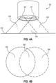
- FIG. 4A depicts a side diagrammatic view of an exemplary set of partially overlapping fields of view that may be captured using an endoscope such as the dual camera endoscope (50), while FIG. 4B depicts a top-down diagrammatic view of the set of partially overlapping fields of view.
- the first camera (60) and the second camera (61) are oriented such that their respective lines of sight to a target surface (100) are parallel.
- the first camera (60) provides a first field of view (102) of the target surface (100), while the second camera (61) provides a second field of view (104) of the target surface (100).
- the first field of view (102) and the second field of view (104) also combine to provide a combined field of view (106), in which the target surface (100) is viewed by each camera, in parallel, from a slightly different position.
- the set of cameras (59) may also be oriented such that their respective lines of sight to the target surface (100) are intersecting, converging, or otherwise oriented toward each other rather than being parallel.
- FIG. 5A shows a side diagrammatic view of an exemplary set of overlapping fields of view of the dual camera endoscope
- FIG. 5B depicts a top-down diagrammatic view of the set of overlapping fields of view.
- the first camera (60) and the second camera (61) are oriented such that their respective lines of sight intersect, converge, or are otherwise oriented toward each other.
- the first camera (60) provides a first field of view (108)), while the second camera (61) provides a second field of view (110), which combine to provide a combined field of view (112).
- the first field of view (108) and the second field of view (110) may perfectly or substantially overlap when producing the combined field of view (112).
- the unique portions of the first field of view (108) and the second field of view (110) may be non-existent or null values.
- the unique portions of the first field of view (108) and the second field of view (110) may include negligible portions of image data at each edge of the combined field of view (112).
- a parallel orientation of the cameras provides a wide overall field of view (e.g., the distance between the outer edges of the first field of view (102) and the second field of view (104) is greater than the distance between the outer edges of the first field of view (108) and the second field of view (110)) and a narrow combined field of view (e.g., the width of the combined field of view (106) is lesser than the width of the combined field of view (112)).
- An intersecting or converging orientation of the cameras provides a narrower overall field of view, as the first field of view (108) and the second field of view (110) substantially or entirely overlap, but the combined field of view (112) is substantially larger.
- Each implementation may be desirable in some instances.
- a wide overall field of view such as that of the first field of view (102) and the second field of view (104) may be useful in producing wide shot or panoramic view images.
- a wide combined field of view such as that of the combined field of view (112) may be useful in producing upscaled images or images that take advantage of parallax image concepts in order to produce stereoscopic or three-dimensional images.
- the set of cameras (59) may, in some implementations, be statically oriented with respect to each other in order to provide the most desirable field of view for certain applications. This may include statically orienting the cameras such that their lines of sight are parallel, as shown in FIG. 4A , or statically orienting the cameras such that their lines of sight intersect at various distances (e.g., where an endoscope is typically positioned 2 inches from a surgical site, a static intersecting orientation may be optimized for such a distance).
- each camera may be rotatably positioned within the distal tip (66) to allow for a limited amount of side-to-side rotation (e.g., yaw) independently of each other.
- the first camera (60) may be rotatably installed within a housing such that an electric actuator may extend or retract and change the orientation of the first camera.
- an electroactive polymer may be integrated into a housing that flexibly biases the first camera to rotate in a first direction, such that electric current received via the same connection that the first camera (60) uses for data communications causes the electroactive polymer to shrink and rotate the camera in a second direction.
- the orientation of the set of cameras may be changed or influenced in varying ways, which will be apparent to one of ordinary skill in the art in light of this disclosure.
- Such dynamic orientation may be performed manually by use of the control (56) and a pull wire or other mechanical actuator, for example; or may be performed automatically by the processor (12) or another device.
- a focused or converging line of sight of the target surface (100) is desired (e.g., like the configuration shown in FIGS.
- the processor (12) may determine the distance between the set of cameras (59) and the target surface (100) and automatically orient each camera (59) in real time so that their lines of sight intersect or converge proximately to the target surface (100), providing an automatically focusing, three-dimensional field of view similar to that of a human.
- Providing a parallax view in this manner may be advantageous in that it provides a sense of depth perception to a viewer; and provides a level of immersion beyond two-dimensional viewing, which may aid in accurate and precise movements and manipulations of surgical tools and other devices.
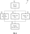
- FIG. 6 depicts a flowchart of an exemplary set of steps (200) that may be performed by a system such as the IGS navigation system (10) to provide enhanced endoscopic views using an endoscope such as the dual camera endoscope (50).
- a three-dimensional view may include an image viewable with a 3D capable monitor or other device such as a head-mounted display (HMD), such as a side-by-side or over-under set of image data; but may also include an image, an animated image or video image, or other set of images that may be displayed on any type of display and that may give a sense of movement, navigation, or depth even when displayed in two dimensions.
- HMD head-mounted display
- this may include creating and displaying an animated image that alternates between the first field of view (108) and the second field of view (110), and that may include one or more intervening images produced by gradually morphing or otherwise combining images from the first field of view (108) and the second field of view (110).
- Such an image may be automatically alternated and displayed in two dimensions, providing a sense of moving and pivoting between the two perspectives (e.g., that of the first camera (60) and that of the second camera (61)).
- Such an image may also be manually alternated or navigated by a user based upon inputs received via a keyboard, mouse, voice input, or other input type, in order to provide an image that a user may view in two dimensions while moving and pivoting between two perspectives.
- Any one or more of these views, as well as views of the original received (block 202) image, may be displayed individually or simultaneously with each other, and may also be displayed (block 210) as a movable view via the display screen (16).
- a movable view may provide a cropped view of another video or image (e.g., a panoramic view or super resolution view) that may be moved using the operating controls (14) to view different areas of the image at varying levels of detail.
- a created panoramic view may be too large for the display screen (16) to display at its true size (e.g., a digital image may be 5000x5000 pixels, and a particular display may only support display of 1680x1050 pixels, meaning that larger images are downscaled for display and image details may be lost or obfuscated).
- the movable view may be moved about a larger image to show particular sections in increased or full detail (e.g., in the above example, 1680x1050 pixels at a time), and may also be configured to respond to navigational inputs via the operating controls (14) as if it were a moving endoscopic camera (e.g., the image may gradually zoom in or out, move horizontally and vertically, or change an angle or orientation, as an endoscopic being moved within the patient would).
- the movable view may create a sense of movement when repositioning its displayed section, such that a surgeon relying upon the displayed images may perceive that they are actually physically repositioning the source endoscope, which may aid the surgeon in perceiving and understanding the spatial relationship of their view of the surgical site. While FIG. 6 provides a high level description of several exemplary display features, FIGS. 7-10 provide more details on steps that may be performed during one or more of the high level steps.
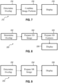
- FIG. 7 depicts a flowchart of an exemplary set of steps (212) that may be performed to provide a panoramic endoscopic view using an endoscope such as the dual camera endoscope (50).
- an endoscope such as the dual camera endoscope (50).
- the teachings herein may be applied to still image as well as sequences of images (e.g., video), the descriptions and figures may at times refer to singular pairs of images for ease of discussion.
- the IGS navigation system (10) will have two images, one from the first camera (60) and one from the second camera (61). Where the cameras are statically positioned and oriented for parallel line of sight (e.g., as shown in FIGS.
- the system may determine (block 214) the overlap of the two images based upon known characteristics of the cameras' positions.
- the combined field of view (106) in FIG. 4B represents an overlap of two images captured by the cameras of that example, and will remain static so long as the cameras do not change their position or orientation, relative to each other.
- the image overlap may be determined (block 214) and configured prior to the time of capture (e.g., the dual camera endoscope (50) may output image data indicating the overlap as a static value, or the IGS navigation system (10) may be configured with such a value or may access or retrieve such a value based upon the type of endoscope in use).
- the amount of overlap may also be determined (block 214) dynamically for an image or video.
- Such dynamic determination (block 214) may be performed per image (e.g., once for each and every pair of received images during a video sequence of images) or for batches of images at a time (e.g., overlap may be determined (block 214) for a first image, and such overlap may be used for the next thirty images, or for any number of images received during the next second), as desired for a particular implementation and as may be possible for a particular processing device.
- Determining overlap dynamically may be performed in varying other ways. In some implementations, this could be performed algorithmically using an image processing and comparison algorithm to compare the first image to the second image in order to identify the matching or substantially matching (e.g., where the two cameras are focused on a single point from two slightly different perspectives) portions, or to identify and corelate a recognizable feature or object that is present within each (e.g., a cutting instrument or other surgical tool within the field of view of an endoscope). In some implementations this could be performed using a proximity sensor positioned on the distal tip (66) that could detect the distance between the target surface (100) and the cameras.
- Such information may be used, along with the relative position and orientation of each camera to the other, to determine the spatial relationship of each image to the other, which will indicate the amount of overlap.
- this could be performed using a visual marker, such as a laser light, projected by a laser fixed or within each camera and aimed at that camera's point of focus, such that each image would contain that images point of focus at its center, as well as the other images point of focus offset from its center, which could then be used to determine (block 214) overlap.
- a visual marker such as a laser light
- the system may then combine (block 216) the two images to create a new panoramic image, and then may display (block 218) the resulting panoramic image via the display screen (16).
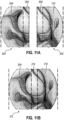
- FIG. 11A shows an image (300) such as might be captured by the second camera (61), and an image (302) such as might be captured by the first camera (60).
- the system may determine (block 214) the overlap of the two images and identify a first outer portion (304), an overlapping portion (306), an overlapping portion (308), and a second outer portion (310) within the images.
- the system may then combine (block 216) the two images at their unique edges, separated by a single overlapping portion, in order to produce a new panoramic image, such as shown in FIG. 11B .
- a new panoramic image (312) has been created by combining the first outer portion (304) with an overlapping portion (314) (e.g., either of the other overlapping portions) and the second outer portion (310).
- the panoramic image (312) created as a result would have a total horizontal resolution of about 3500 pixels, providing a significant increase in the area of the image that could be viewable at the highest resolution and detail possible, if desired.
- FIG. 8 shows a flowchart of an exemplary set of steps (220) that may be performed to provide a three-dimensional endoscopic view using an endoscope such as the dual camera endoscope (50).
- the system may first determine (block 222) the overlap between the two input images, in order to determine the spatial relationship between the two fields of view from which the images were captured.
- the system may then prepare (block 224) a 3D image, the format and features of which may be dependent upon a device or devices that it is intended to be viewed on.
- preparing (block 224) a 3D image may include cropping the input images to exclude edge portions or non-overlapping portions, and arranging the remaining image portions side-by-side so that a viewer's eyes can independently focus on the two slightly varying image perspectives when they are displayed (block 226) via the two viewing lenses of the HMD.
- the 3D image may be prepared (block 224) to display on displays capable of displaying 2D images while simulating depth or movement between perspectives, as has been described above.
- This may include preparing (block 224) the image as an animated image, video image, or one or more side-by-side images, and alternating between displaying images from different perspectives (e.g., one from the first camera (60) and one from the second camera (61)).
- This may also include producing one or more intervening images by morphing source images from different perspectives to provide multiple viewing angles in between.
- a 3D image prepared (block 224) to provide one or more of these features may allow a user to view the images in 2D, with the ability to manually or automatically shift perspectives to provide a sense of pivoting or rotating around the target surface (100), as opposed to just panning or moving across it. Viewing such an image may advantageously provide an improved sense of depth and spatial positioning, as opposed to a static 2D image.
- Preparing (block 224) the 3D image dataset may also include preparing (block 225) one or more 3D datasets or additional 3D features.
- some implementations may use 3D image data to produce depth measurements, topographical indicators, or other depth and distance indicators associated with the target surface (100).
- depth indicators may include one or more of a distance marker showing one or more dimensions of an anatomical structure within the 3D field of view. This may be determined by performing a visual analysis and comparison of a targeted anatomical structure from two or more perspectives in order to take advantage of the parallax view and estimate a depth of the targeted object.
- Another depth indicator may include a topographical map or overlay showing, via variations in displayed colors, patterns, or other visual indicators, topographical characteristics of an anatomical structure within the 3D field of view. This may be also be determined using the captured parallax view; and may be overlaid upon and displayed (block 226) with the source image or displayed (block 226) independently of the source image.
- a 3D feature that may be prepared (blocked 225) using the 3D image data is a measurement of volume of an anatomical structure within the 3D field of view.
- the system may also determine a length and width, a circumference, or other dimensional measurements of an anatomical structure. This may include automatically determining the scale of the captured image using information such as the distance between the camera and the anatomical structure (e.g., as provided by a proximity sensor used to focus and converge two fields of view at a target surface or object).
- a determination of volume of a targeted anatomical structure may be useful in providing an indication of an amount of tissue, bone, or other material that must be removed or affected during a procedure.
- a determined volume of an anatomical structure may also be useful to provide a comparison point between pre-operative and post-operative anatomical structures; and may provide an indication of the level of success of a procedure, a patient recovery time, or a need for additional procedures.
- Such comparisons between pre-operative and post-operative anatomical structures may include visual comparisons of endoscopic images, as well as visual or numeric indicators of change of volume, depth, and topography.
- a system having one or more of these describes features may also include any of the teachings of U.S. Pat. App. 62/779,614, entitled "Surgical System with Combination of Sensor-Based Navigation and Endoscopy", filed December 14, 2018 .
- FIG. 9 shows a flowchart of an exemplary set of steps (230) that may be performed to provide a super resolution endoscopic view using an endoscope such as the dual camera endoscope (50).
- the system may first determine (block 232) an amount of overlap between the two input images.
- the system may then prepare (block 234) a super resolution image from the combined, overlapping portions of the two input images, and display (block 236) the resulting image at a higher resolution than its input images.
- Super resolution is an image processing technique that can combined overlapping or substantially overlapping images in order to produce an output image of higher resolution than its input image data, and with reduced digital noise and other visual artifacts that may be introduced during digital imaging.
- FIG. 10 shows a flowchart of an exemplary set of steps (240) that may be performed to provide movable view, or a visualization window, for one or more enhanced endoscopic views, such as the panoramic view or super resolution view described above.
- the system may display (block 242) a visualization window via the display screen (16) as a real-time endoscopic image or video, showing a view of a surgical site.
- the image shown in the visualization window may be a section of a received (block 202) image, or may be a section of an image created from a received (block 202) image by steps such as those shown in FIGS. 7-9 .
- a panoramic image that has been created by combining (block 216) portions of input images may be 3000x2000 while the visualization window may show a 1000x1000 pixel area, meaning that only about 15% of the image may be shown within the visualization window at any one time.
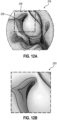
- FIG. 12A shows an image (316) captured by an endoscope such as the dual camera endoscope (50), which may be a normal image, panoramic image, super resolution image, or other image type captured or created by the system.
- a visualization window (318) is depicted as a box overlaid upon the larger image (316).
- FIG. 12B shows a viewable section (320) of the image (316) that is contained within the visualization window (318).
- the viewable section (320) may be displayed via the display screen (16) at a desired resolution that is supported by the display screen (16), such that the viewable section (320) the surgical site may be viewed at a high level of detail (e.g., the maximum resolution supported by the display screen (16) without any downscaling) if desired.
- a user may interact with a set of user input devices such as the operating controls (14) in order to move and reposition the visualization window (318) on a desired section of the larger image (316). This may include interacting with a touch screen to touch and drag to a new section of an image, interacting with software buttons to move the view in a desired direction, using a keyboard or mouse to scroll the view, and other types of input.
- a set of user input devices such as the operating controls (14) in order to move and reposition the visualization window (318) on a desired section of the larger image (316).
- This may include interacting with a touch screen to touch and drag to a new section of an image, interacting with software buttons to move the view in a desired direction, using a keyboard or mouse to scroll the view, and other types of input.
- the visualization window (318) and resulting display may be updated to reflect a movement of the window relative to the larger image (e.g., the smaller visualization window moving across the larger image to display new sections) or a change in size of the window relative to the larger image (e.g., the size of the section displayed by the visualization window changes, simulating a movement inwards outwards).
- Changes in the visualization window may be displayed gradually to simulate the feeling or experience of motion within a three dimensional space, such as might be experienced when an endoscope providing the image is actually moved (e.g., moved upwards or downwards, advanced or retracted, orientationally rotated).
- Some implementations may also allow the visualization window to be rotated to cause a corresponding change to the orientation of the perspective from which the image is viewed. This may be accomplished by applying image processing algorithms to modify and redisplay the image in real-time. This could produce a visual effect similar to that of the endoscope rotating, or a movable lens of the endoscope rotating (e.g., around the x-axis or the y-axis).
- Image processing to shift perspectives of an image may benefit from having more detailed and higher resolution input images in order to produce realistic looking, perspective shifted output images, and thus may be advantageously applied to panoramic images, super resolution images, and other images captured or created according to one or more of the techniques described herein.
- the system will determine (block 246) whether they indicate a movement, such as panning, of the visualization window horizontally, vertically, or both, and in response may gradually transition (block 248) the visualization window to the new section. Display in this manner may simulate a movement of the endoscope horizontally (e.g., along the x-axis) and vertically (e.g., along the y-axis) relative to the surgical site or other viewed target.
- the system may also determine (block 250) whether the inputs indicate a movement, such as zooming, of the visualization window towards the surgical site or away from the surgical site, and in response may gradually change (block 252) the size or magnification level of the section displayed within the visualization window to the new size. Display in this manner may simulate an advance or withdrawal of the endoscope (e.g., along the z-axis) relative to the surgical site or other viewed target.
- a movement such as zooming
- the system may also determine (block 254) whether the inputs indicate a rotational change or perspective change of the visualization window relative to surgical site, and in response may gradually change (block 256) the perspective of the section displayed within the visualization window to the new perspective.
- Change (block 256) of the perspective may be limited within configurable boundaries in order to prevent changes in viewing perspective that would result in perspective shifted output images of low quality (e.g., where automatic reduction or introduction of pixels within an area of the image exceeds a configured threshold) or of a perspective that is so obviously skewed that it breaks the sense of immersion of a viewer.
- Display in this manner may simulate a rotational or angular change of the endoscope relative to the surgical site or other viewed target.
- images from the first field of view (108) and the second field of view (110) may be manually panned or pivoted between to provide a sense of pivoting between two perspectives, even when viewed two-dimensionally.
- Any intervening images that may be produced by gradually morphing between or otherwise combining the two source images from the first camera (60) and the second camera (61) may simulate and be viewable as multiple viewing angles present between the first camera (60) and the second camera (61).
- the speed and responsiveness of visualization window transitions (block 248), size changes (block 252), and perspectives changes (block 256) may be configured to provide a sense of steady movement within three-dimensional space, while the perspective of the source image and endoscope themselves do not change.
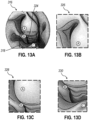
- FIGS. 13A-13D show a set of simulated images that may be displayed during use and navigation of the visualization window, for example, when the visualization window (318) is moved from the position shown in FIG. 12A to the position shown in FIG. 13A .
- a set of reference points labeled A, B, and C are overlaid upon the source image (316) for the purpose of describing the simulated images.
- FIG. 13B shows an origin image (326) that displays a section of the source image (316) contained within the visualization window (318) at its starting point shown in FIG. 12A .
- FIG. 13C shows a transitional image (328) that would be contained within the visualization window (318) as it transitions (block 248) to a new section of the source image (316), as a result of user input.
- the visualization window (318) has moved vertically downwards and horizontally to the right relative to FIG. 13B.
- FIG. 13D shows a destination image (330) that displays a section of the source image (316) contained within the visualization window (318) at its ending point shown in FIG. 13A .
- the reference points B and C show that the visualization window (318) has moved vertically downwards and horizontally to the right relative to FIG. 13C .
- any number of transition images as may be desired can be displayed in between the origin and destination to provide a sense of gradual and smooth movement to the destination in response to user input.
- Versions of the devices disclosed herein can be designed to be disposed of after a single use, or they can be designed to be used multiple times. Versions may, in either or both cases, be reconditioned for reuse after at least one use. Reconditioning may include any combination of the steps of disassembly of the device, followed by cleaning or replacement of particular pieces, and subsequent reassembly. In particular, versions of the device may be disassembled, and any number of the particular pieces or parts of the device may be selectively replaced or removed in any combination. Upon cleaning and/or replacement of particular parts, versions of the device may be reassembled for subsequent use either at a reconditioning facility, or by a surgical team immediately prior to a surgical procedure.
- reconditioning of a device may utilize a variety of techniques for disassembly, cleaning/replacement, and reassembly. Use of such techniques, and the resulting reconditioned device, are all within the scope of the present application.
- versions described herein may be processed before surgery.
- a new or used instrument may be obtained and if necessary cleaned.
- the instrument may then be sterilized.
- the instrument is placed in a closed and sealed container, such as a plastic or TYVEK bag.
- the container and instrument may then be placed in a field of radiation that can penetrate the container, such as gamma radiation, x-rays, or high-energy electrons.
- the radiation may kill bacteria on the instrument and in the container.
- the sterilized instrument may then be stored in the sterile container.
- the sealed container may keep the instrument sterile until it is opened in a surgical facility.
- a device may also be sterilized using any other technique known in the art, including but not limited to beta or gamma radiation, ethylene oxide, or steam.
Landscapes
- Health & Medical Sciences (AREA)
- Life Sciences & Earth Sciences (AREA)
- Physics & Mathematics (AREA)
- Surgery (AREA)
- Optics & Photonics (AREA)
- Engineering & Computer Science (AREA)
- General Health & Medical Sciences (AREA)
- Radiology & Medical Imaging (AREA)
- Animal Behavior & Ethology (AREA)
- Heart & Thoracic Surgery (AREA)
- Veterinary Medicine (AREA)
- Biophysics (AREA)
- Nuclear Medicine, Radiotherapy & Molecular Imaging (AREA)
- Pathology (AREA)
- Biomedical Technology (AREA)
- Public Health (AREA)
- Medical Informatics (AREA)
- Molecular Biology (AREA)
- General Physics & Mathematics (AREA)
- Astronomy & Astrophysics (AREA)
- Signal Processing (AREA)
- Multimedia (AREA)
- Endoscopes (AREA)
- Instruments For Viewing The Inside Of Hollow Bodies (AREA)
Claims (12)
- Système comprenant :(a) un endoscope (50) comprenant :(i) une unité de couplage (54),(ii) un arbre (52) s'étendant à partir de l'unité de couplage, et(iii) un ensemble de caméras (59) positionné à une extrémité distale de l'arbre, dans lequel l'ensemble de caméras est exploitable pour capturer et communiquer des données d'image à l'unité de couplage ;(b) un processeur d'images (12) configuré pour recevoir des données d'images provenant de l'unité de couplage ; et(c) un afficheur (16) ;dans lequel le processeur d'images est configuré pour :(i) recevoir une première image (108) provenant d'une première caméra (60) de l'ensemble de caméras et recevoir une deuxième image (110) provenant d'une seconde caméra (61) de l'ensemble de caméras,(ii) déterminer une partie unique de première image, une partie chevauchante et une partie unique de deuxième image sur la base de la première image et de la deuxième image,(iii) créer une image améliorée sur la base de la partie unique de première image, la partie chevauchante et la partie unique de deuxième image tout d'abord en(a) déterminant que la première image et la deuxième image se chevauchent parfaitement ou sensiblement, de telle sorte que la partie unique de première image et la partie unique de deuxième image ne contiennent pas de données d'image ou contiennent des données d'image négligeables, puis en(b) combinant la partie chevauchante provenant de la première image et de la deuxième image pour créer une image à super résolution, dans lequel l'image à super résolution comprend une résolution supérieure à celle de la partie chevauchante, et(iv) fournir une fenêtre de visualisation (318) qui affiche une section actuelle (320) de l'image améliorée par le biais de l'afficheur.
- Système selon la revendication 1, dans lequel le processeur d'images est en outre configuré pour, lors de la création de l'image améliorée, combiner la partie unique de première image, la partie chevauchante et la partie unique de deuxième image pour créer une image panoramique, dans lequel l'image panoramique comprend une résolution supérieure à celle de la première image et de la deuxième image.
- Système selon la revendication 1 ou la revendication 2, dans lequel le processeur d'image est en outre configuré pour, lors de la création de l'image améliorée, créer une image 3D de la partie chevauchante, dans lequel l'image 3D est configurée pour être affichée sous la forme de :(i) une image qui est visualisable en trois dimensions sur un afficheur tridimensionnel, et(ii) une image qui est visualisable en trois dimensions sur un afficheur bidimensionnel en pivotant d'avant en arrière entre une première perspective de la partie chevauchante et une seconde perspective de la partie chevauchante.
- Système selon une quelconque revendication précédente, dans lequel la première caméra et la seconde caméra sont orientées de telle sorte que la première caméra et la seconde caméra ont des lignes de visée respectives qui sont parallèles l'une à l'autre, et dans lequel le processeur est en outre configuré pour déterminer la partie chevauchante sur la base de la première image, de la seconde image et d'une valeur de chevauchement statique, dans lequel la valeur de chevauchement statique est déterminée sur la base d'une distance entre la position de la première caméra et de la seconde caméra sur la pointe distale.
- Système selon une quelconque revendication précédente, comprenant en outre un ensemble de commandes de fonctionnement, dans lequel le processeur d'images est en outre configuré pour :(i) recevoir un ensemble d'entrées par l'intermédiaire de l'ensemble de commandes de fonctionnement, et(ii) mettre à jour la section actuelle affichée dans la fenêtre de visualisation sur la base de l'ensemble d'entrées.
- Système selon la revendication 5, dans lequel le processeur d'images est en outre configuré pour, lorsque l'ensemble d'entrées comprend une entrée indiquant un mouvement de la fenêtre de visualisation le long d'un ou de plusieurs de l'axe x et de l'axe y :(i) déterminer une section de destination de l'image améliorée sur la base de l'entrée et de la section actuelle, et(ii) rafraîchir et fournir la fenêtre de visualisation en utilisant la section de destination comme section actuelle.
- Système selon la revendication 6, dans lequel le processeur d'images est en outre configuré pour, lors du rafraîchissement et de la fourniture de la fenêtre de visualisation en utilisant la section de destination comme section actuelle :(i) déterminer une ou plusieurs sections de transition de l'image améliorée situées entre la section actuelle et la section de destination, et(ii) afficher la ou les sections de transition dans une séquence ordonnée avant d'afficher la section de destination.
- Système selon l'une quelconque des revendications 5 à 7, dans lequel le processeur d'image est en outre configuré pour, lorsque l'ensemble d'entrées comprend une entrée indiquant un mouvement de la fenêtre de visualisation le long de l'axe z :(i) déterminer un nouveau niveau d'agrandissement sur la base de l'entrée, et(ii) rafraîchir et afficher de nouveau la fenêtre de visualisation sur la base de la section actuelle et du nouveau niveau d'agrandissement.
- Système selon la revendication 8, dans lequel le processeur d'images est en outre configuré pour, lors du rafraîchissement et de la fourniture de la fenêtre de visualisation sur la base de la section actuelle et du nouveau niveau d'agrandissement :(i) déterminer un ou plusieurs agrandissements de transition de l'image améliorée situés entre la section actuelle à un niveau d'agrandissement original et la section actuelle au nouveau niveau d'agrandissement, et(ii) afficher le ou les agrandissements de transition dans une séquence ordonnée avant d'afficher la section actuelle au nouveau niveau d'agrandissement.
- Système selon l'une quelconque des revendications 5 à 9, dans lequel le processeur d'images est en outre configuré pour, lorsque l'ensemble d'entrées comprend une entrée indiquant une rotation d'une perspective de la fenêtre de visualisation :(i) déterminer une perspective de destination sur la base de l'entrée,(ii) modifier numériquement la section actuelle de l'image améliorée sur la base de la perspective de destination, et(iii) rafraîchir et fournir la fenêtre de visualisation sur la base de la section actuelle modifiée numériquement.
- Système selon la revendication 10, dans lequel le processeur est en outre configuré pour, lors de la création de l'image améliorée, combiner la première image et la deuxième image pour produire une troisième image, dans lequel la troisième image comprend une résolution plus élevée que la première image et la deuxième image.
- Système selon une quelconque revendication précédente, dans lequel chaque caméra de l'ensemble de caméras comprend un dispositif d'imagerie numérique, dans lequel chaque caméra de l'ensemble de caméras est configurée pour fournir des données d'image à l'unité de couplage par le biais d'une connexion conductrice à l'intérieur de l'arbre, et dans lequel le processeur d'image est un processeur d'un système de navigation chirurgicale guidée par l'image.
Applications Claiming Priority (3)
| Application Number | Priority Date | Filing Date | Title |
|---|---|---|---|
| US201862782697P | 2018-12-20 | 2018-12-20 | |
| US16/695,500 US10955657B2 (en) | 2018-12-20 | 2019-11-26 | Endoscope with dual image sensors |
| PCT/IB2019/060797 WO2020128765A1 (fr) | 2018-12-20 | 2019-12-13 | Endoscope à capteurs d'images doubles |
Publications (3)
| Publication Number | Publication Date |
|---|---|
| EP3897340A1 EP3897340A1 (fr) | 2021-10-27 |
| EP3897340B1 true EP3897340B1 (fr) | 2025-03-05 |
| EP3897340C0 EP3897340C0 (fr) | 2025-03-05 |
Family
ID=71097641
Family Applications (1)
| Application Number | Title | Priority Date | Filing Date |
|---|---|---|---|
| EP19832456.8A Active EP3897340B1 (fr) | 2018-12-20 | 2019-12-13 | Endoscope à capteurs d'images doubles |
Country Status (5)
| Country | Link |
|---|---|
| US (1) | US10955657B2 (fr) |
| EP (1) | EP3897340B1 (fr) |
| JP (1) | JP7460631B2 (fr) |
| CN (1) | CN113453606B (fr) |
| WO (1) | WO2020128765A1 (fr) |
Families Citing this family (19)
| Publication number | Priority date | Publication date | Assignee | Title |
|---|---|---|---|---|
| US10955657B2 (en) * | 2018-12-20 | 2021-03-23 | Acclarent, Inc. | Endoscope with dual image sensors |
| WO2021064867A1 (fr) * | 2019-10-01 | 2021-04-08 | 日本電気株式会社 | Dispositif de traitement d'image, procédé de commande et support de stockage |
| CN114846434A (zh) * | 2019-10-25 | 2022-08-02 | 奇跃公司 | 非均匀立体渲染 |
| US11357580B2 (en) * | 2020-04-10 | 2022-06-14 | Smith & Nephew, Inc. | Reciprocal optical tracking system and methods thereof |
| WO2022066781A1 (fr) * | 2020-09-23 | 2022-03-31 | Proprio, Inc. | Systèmes d'imagerie endoscopique pour générer des images tridimensionnelles, et systèmes et procédés associés |
| CN113952033B (zh) * | 2021-12-21 | 2022-04-19 | 广东欧谱曼迪科技有限公司 | 一种双源内窥手术导航系统及方法 |
| WO2023187511A2 (fr) | 2022-03-31 | 2023-10-05 | Acclarent, Inc. | Arbre de guidage orl doté d'une pointe pouvant être déviée et d'un capuchon d'endoscope distal |
| CN114979487B (zh) * | 2022-05-27 | 2024-06-18 | 联想(北京)有限公司 | 图像处理方法、装置及电子设备和存储介质 |
| CN115054186A (zh) * | 2022-06-27 | 2022-09-16 | 上海可映康科技有限公司 | 用于软式内窥镜的介入针、软式内窥镜和软式内窥镜系统 |
| CN114931348A (zh) * | 2022-06-27 | 2022-08-23 | 上海可映康科技有限公司 | 用于硬式内窥镜的介入针和硬式内窥镜 |
| EP4583753A1 (fr) * | 2022-09-20 | 2025-07-16 | Psip2 Llc | Traitement d'image de vidéo d'endoscope |
| CN115956859B (zh) | 2022-10-11 | 2026-04-14 | 中国医学科学院北京协和医院 | 内窥镜控制方法及手术机器人系统 |
| CN115517615B (zh) * | 2022-10-11 | 2026-03-24 | 中国医学科学院北京协和医院 | 内窥镜主从运动控制方法及手术机器人系统 |
| CN116016890B (zh) * | 2022-12-29 | 2025-07-22 | 杭州海康慧影科技有限公司 | 一种图像显示方法、系统、装置及设备 |
| WO2024150063A1 (fr) | 2023-01-12 | 2024-07-18 | Acclarent, Inc. | Appareil et procédé pour déterminer une orientation de roulis d'endoscope sur la base d'une analyse d'image |
| JP2026508893A (ja) * | 2023-03-07 | 2026-03-13 | アースレックス インコーポレイテッド | 選択的ビューを有する外科手術撮像システム |
| JP2026511294A (ja) * | 2023-03-28 | 2026-04-13 | アルコン インコーポレイティド | 眼科撮影システムのための画像補正 |
| US20250152035A1 (en) | 2023-11-10 | 2025-05-15 | Acclarent, Inc. | Flex circuit with longitudinally-spaced position sensors for steerable medical instrument |
| JP7733754B2 (ja) * | 2024-01-18 | 2025-09-03 | 株式会社フジクラ | 画像処理方法、画像処理装置、画像処理プログラム、及び内視鏡システム |
Family Cites Families (40)
| Publication number | Priority date | Publication date | Assignee | Title |
|---|---|---|---|---|
| US188467A (en) * | 1877-03-20 | Improvement in lifting-jacks for carriages | ||
| JPH03289929A (ja) * | 1990-04-06 | 1991-12-19 | Toshiba Corp | 電子内視鏡装置 |
| US5417210A (en) * | 1992-05-27 | 1995-05-23 | International Business Machines Corporation | System and method for augmentation of endoscopic surgery |
| DE4141397C2 (de) * | 1991-12-16 | 1994-12-22 | Augustin Imhof | Verfahren zum Messen von Sprungweiten im Skisport |
| US5515301A (en) * | 1994-06-29 | 1996-05-07 | General Electric Company | Real-time visualization system for multiple time-sampled signals |
| JPH095643A (ja) | 1995-06-26 | 1997-01-10 | Matsushita Electric Ind Co Ltd | 立体内視鏡装置 |
| JP3955126B2 (ja) * | 1997-05-14 | 2007-08-08 | オリンパス株式会社 | 内視鏡の視野変換装置 |
| US20020063711A1 (en) * | 1999-05-12 | 2002-05-30 | Imove Inc. | Camera system with high resolution image inside a wide angle view |
| US7194118B1 (en) * | 2000-11-10 | 2007-03-20 | Lucid, Inc. | System for optically sectioning and mapping surgically excised tissue |
| AU2004277273A1 (en) * | 2003-09-22 | 2005-04-07 | Gene Dolgoff | Omnidirectional lenticular and barrier-grid image display |
| US20070208252A1 (en) * | 2004-04-21 | 2007-09-06 | Acclarent, Inc. | Systems and methods for performing image guided procedures within the ear, nose, throat and paranasal sinuses |
| US7720521B2 (en) * | 2004-04-21 | 2010-05-18 | Acclarent, Inc. | Methods and devices for performing procedures within the ear, nose, throat and paranasal sinuses |
| US20100331883A1 (en) * | 2004-10-15 | 2010-12-30 | Schmitz Gregory P | Access and tissue modification systems and methods |
| WO2009144729A1 (fr) | 2008-05-28 | 2009-12-03 | Technion Research & Development Foundation Ltd. | Ensemble de caméras laparoscopiques |
| JP2010125270A (ja) * | 2008-12-01 | 2010-06-10 | Hoya Corp | 内視鏡装置 |
| CA2941578A1 (fr) * | 2010-09-08 | 2012-03-15 | Covidien Lp | Catheter pourvu d'un ensemble d'imagerie |
| JP5670945B2 (ja) * | 2012-04-02 | 2015-02-18 | 株式会社東芝 | 画像処理装置、方法、及びプログラム、並びに、立体画像表示装置 |
| JP2013244362A (ja) | 2012-05-29 | 2013-12-09 | Olympus Corp | 立体視内視鏡システム |
| US9629523B2 (en) * | 2012-06-27 | 2017-04-25 | Camplex, Inc. | Binocular viewing assembly for a surgical visualization system |
| US11278182B2 (en) * | 2012-06-28 | 2022-03-22 | Koninklijke Philips N.V. | Enhanced visualization of blood vessels using a robotically steered endoscope |
| US9198835B2 (en) * | 2012-09-07 | 2015-12-01 | Covidien Lp | Catheter with imaging assembly with placement aid and related methods therefor |
| JP5730339B2 (ja) | 2013-01-25 | 2015-06-10 | 富士フイルム株式会社 | 立体内視鏡装置 |
| US10314559B2 (en) * | 2013-03-14 | 2019-06-11 | Inneroptic Technology, Inc. | Medical device guidance |
| WO2014189969A1 (fr) * | 2013-05-21 | 2014-11-27 | Camplex, Inc. | Systèmes de visualisation chirurgicaux |
| US10515110B2 (en) * | 2013-11-12 | 2019-12-24 | Pinterest, Inc. | Image based search |
| CA2933704A1 (fr) * | 2013-12-13 | 2015-06-18 | 8702209 Canada Inc. | Systemes et procedes de production de videos panoramiques et stereoscopiques |
| WO2015151094A1 (fr) * | 2014-04-02 | 2015-10-08 | M.S.T. Medical Surgery Technologies Ltd. | Endoscope présentant un objectif grand-angulaire et une vue réglable |
| US10463242B2 (en) | 2014-07-09 | 2019-11-05 | Acclarent, Inc. | Guidewire navigation for sinuplasty |
| US10188467B2 (en) * | 2014-12-12 | 2019-01-29 | Inneroptic Technology, Inc. | Surgical guidance intersection display |
| EP3297515B1 (fr) * | 2015-05-17 | 2020-07-01 | Endochoice, Inc. | Amélioration d'image endoscopique par égalisation d'histogramme adaptative à contraste limité (clahe) mise en oeuvre dans un processeur |
| US9726896B2 (en) * | 2016-04-21 | 2017-08-08 | Maximilian Ralph Peter von und zu Liechtenstein | Virtual monitor display technique for augmented reality environments |
| US10181391B2 (en) * | 2016-05-26 | 2019-01-15 | Nanojehm Inc. | Image processing system and method of processing images |
| US10992917B2 (en) | 2016-06-17 | 2021-04-27 | Sony Corporation | Image processing device, image processing method, program, and image processing system that use parallax information |
| US11026747B2 (en) * | 2017-04-25 | 2021-06-08 | Biosense Webster (Israel) Ltd. | Endoscopic view of invasive procedures in narrow passages |
| WO2018217951A1 (fr) * | 2017-05-24 | 2018-11-29 | Camplex, Inc. | Systèmes de visualisation chirurgicale et dispositifs d'affichage |
| US11424027B2 (en) * | 2017-12-28 | 2022-08-23 | Cilag Gmbh International | Method for operating surgical instrument systems |
| US11457981B2 (en) * | 2018-10-04 | 2022-10-04 | Acclarent, Inc. | Computerized tomography (CT) image correction using position and direction (P andD) tracking assisted optical visualization |
| WO2020117941A1 (fr) * | 2018-12-05 | 2020-06-11 | Stryker Corporation | Systèmes et procédés d'affichage de données d'imagerie médicale |
| US10955657B2 (en) * | 2018-12-20 | 2021-03-23 | Acclarent, Inc. | Endoscope with dual image sensors |
| US11633083B2 (en) * | 2018-12-20 | 2023-04-25 | Acclarent, Inc. | 3D scanning of nasal tract with deflectable endoscope |
-
2019
- 2019-11-26 US US16/695,500 patent/US10955657B2/en active Active
- 2019-12-13 CN CN201980092710.2A patent/CN113453606B/zh active Active
- 2019-12-13 WO PCT/IB2019/060797 patent/WO2020128765A1/fr not_active Ceased
- 2019-12-13 JP JP2021535800A patent/JP7460631B2/ja active Active
- 2019-12-13 EP EP19832456.8A patent/EP3897340B1/fr active Active
Also Published As
| Publication number | Publication date |
|---|---|
| JP7460631B2 (ja) | 2024-04-02 |
| EP3897340A1 (fr) | 2021-10-27 |
| JP2022514635A (ja) | 2022-02-14 |
| WO2020128765A1 (fr) | 2020-06-25 |
| US10955657B2 (en) | 2021-03-23 |
| EP3897340C0 (fr) | 2025-03-05 |
| US20200201022A1 (en) | 2020-06-25 |
| CN113453606A (zh) | 2021-09-28 |
| CN113453606B (zh) | 2024-10-01 |
Similar Documents
| Publication | Publication Date | Title |
|---|---|---|
| EP3897340B1 (fr) | Endoscope à capteurs d'images doubles | |
| JP7662627B2 (ja) | Ent処置の可視化システム及び方法 | |
| JP7816722B2 (ja) | センサベースのナビゲーションと内視鏡検査との組み合わせを用いた外科用システム | |
| JP7443353B2 (ja) | 位置及び方向(p&d)追跡支援の光学的視覚化を使用したコンピュータ断層撮影(ct)画像の補正 | |
| US10835344B2 (en) | Display of preoperative and intraoperative images | |
| US9289267B2 (en) | Method and apparatus for minimally invasive surgery using endoscopes | |
| US20230165640A1 (en) | Extended reality systems with three-dimensional visualizations of medical image scan slices | |
| US7774044B2 (en) | System and method for augmented reality navigation in a medical intervention procedure | |
| JP5372225B2 (ja) | コンピュータディスプレイ画面の境界領域に表示されるツール位置および識別指標 | |
| US8414476B2 (en) | Method for using variable direction of view endoscopy in conjunction with image guided surgical systems | |
| JP5055352B2 (ja) | 患者の体との関係で手術器具を三次元トラッキングするためのシステム | |
| EP2641561A1 (fr) | Système et procédé de détermination d'angles de caméra en utilisant des plans virtuels dérivés d'images réelles | |
| US20050054895A1 (en) | Method for using variable direction of view endoscopy in conjunction with image guided surgical systems | |
| EP3311251A1 (fr) | Système, dispositif et procédé d'imagerie de réalité augmentée | |
| JP2008532602A (ja) | 外科手術ナビゲーションと顕微鏡による可視化の方法と装置 | |
| WO2008066944A9 (fr) | Manipulateur éloigné avec globes oculaires | |
| CN112888395B (zh) | 用于实时更新穿行摄像机放置的方法 | |
| JP2024525733A (ja) | 手術前及び手術中のシーンの画像データを表示する方法及びシステム |
Legal Events
| Date | Code | Title | Description |
|---|---|---|---|
| STAA | Information on the status of an ep patent application or granted ep patent |
Free format text: STATUS: UNKNOWN |
|
| STAA | Information on the status of an ep patent application or granted ep patent |
Free format text: STATUS: THE INTERNATIONAL PUBLICATION HAS BEEN MADE |
|
| PUAI | Public reference made under article 153(3) epc to a published international application that has entered the european phase |
Free format text: ORIGINAL CODE: 0009012 |
|
| STAA | Information on the status of an ep patent application or granted ep patent |
Free format text: STATUS: REQUEST FOR EXAMINATION WAS MADE |
|
| 17P | Request for examination filed |
Effective date: 20210629 |
|
| AK | Designated contracting states |
Kind code of ref document: A1 Designated state(s): AL AT BE BG CH CY CZ DE DK EE ES FI FR GB GR HR HU IE IS IT LI LT LU LV MC MK MT NL NO PL PT RO RS SE SI SK SM TR |
|
| DAV | Request for validation of the european patent (deleted) | ||
| DAX | Request for extension of the european patent (deleted) | ||
| GRAP | Despatch of communication of intention to grant a patent |
Free format text: ORIGINAL CODE: EPIDOSNIGR1 |
|
| STAA | Information on the status of an ep patent application or granted ep patent |
Free format text: STATUS: GRANT OF PATENT IS INTENDED |
|
| INTG | Intention to grant announced |
Effective date: 20240515 |
|
| RAP3 | Party data changed (applicant data changed or rights of an application transferred) |
Owner name: BIOSENSE WEBSTER (ISRAEL) LTD. Owner name: ACCLARENT, INC. |
|
| GRAJ | Information related to disapproval of communication of intention to grant by the applicant or resumption of examination proceedings by the epo deleted |
Free format text: ORIGINAL CODE: EPIDOSDIGR1 |
|
| STAA | Information on the status of an ep patent application or granted ep patent |
Free format text: STATUS: REQUEST FOR EXAMINATION WAS MADE |
|
| GRAP | Despatch of communication of intention to grant a patent |
Free format text: ORIGINAL CODE: EPIDOSNIGR1 |
|
| STAA | Information on the status of an ep patent application or granted ep patent |
Free format text: STATUS: GRANT OF PATENT IS INTENDED |
|
| INTC | Intention to grant announced (deleted) | ||
| INTG | Intention to grant announced |
Effective date: 20240925 |
|
| GRAS | Grant fee paid |
Free format text: ORIGINAL CODE: EPIDOSNIGR3 |
|
| GRAA | (expected) grant |
Free format text: ORIGINAL CODE: 0009210 |
|
| STAA | Information on the status of an ep patent application or granted ep patent |
Free format text: STATUS: THE PATENT HAS BEEN GRANTED |
|
| AK | Designated contracting states |
Kind code of ref document: B1 Designated state(s): AL AT BE BG CH CY CZ DE DK EE ES FI FR GB GR HR HU IE IS IT LI LT LU LV MC MK MT NL NO PL PT RO RS SE SI SK SM TR |
|
| REG | Reference to a national code |
Ref country code: GB Ref legal event code: FG4D |
|
| REG | Reference to a national code |
Ref country code: CH Ref legal event code: EP |
|
| REG | Reference to a national code |
Ref country code: DE Ref legal event code: R096 Ref document number: 602019066980 Country of ref document: DE |
|
| REG | Reference to a national code |
Ref country code: IE Ref legal event code: FG4D |
|
| U01 | Request for unitary effect filed |
Effective date: 20250313 |
|
| U07 | Unitary effect registered |
Designated state(s): AT BE BG DE DK EE FI FR IT LT LU LV MT NL PT RO SE SI Effective date: 20250320 |
|
| PG25 | Lapsed in a contracting state [announced via postgrant information from national office to epo] |
Ref country code: RS Free format text: LAPSE BECAUSE OF FAILURE TO SUBMIT A TRANSLATION OF THE DESCRIPTION OR TO PAY THE FEE WITHIN THE PRESCRIBED TIME-LIMIT Effective date: 20250605 |
|
| PG25 | Lapsed in a contracting state [announced via postgrant information from national office to epo] |
Ref country code: ES Free format text: LAPSE BECAUSE OF FAILURE TO SUBMIT A TRANSLATION OF THE DESCRIPTION OR TO PAY THE FEE WITHIN THE PRESCRIBED TIME-LIMIT Effective date: 20250305 |
|
| PG25 | Lapsed in a contracting state [announced via postgrant information from national office to epo] |
Ref country code: NO Free format text: LAPSE BECAUSE OF FAILURE TO SUBMIT A TRANSLATION OF THE DESCRIPTION OR TO PAY THE FEE WITHIN THE PRESCRIBED TIME-LIMIT Effective date: 20250605 |
|
| PG25 | Lapsed in a contracting state [announced via postgrant information from national office to epo] |
Ref country code: HR Free format text: LAPSE BECAUSE OF FAILURE TO SUBMIT A TRANSLATION OF THE DESCRIPTION OR TO PAY THE FEE WITHIN THE PRESCRIBED TIME-LIMIT Effective date: 20250305 |
|
| PG25 | Lapsed in a contracting state [announced via postgrant information from national office to epo] |
Ref country code: GR Free format text: LAPSE BECAUSE OF FAILURE TO SUBMIT A TRANSLATION OF THE DESCRIPTION OR TO PAY THE FEE WITHIN THE PRESCRIBED TIME-LIMIT Effective date: 20250606 |
|
| PG25 | Lapsed in a contracting state [announced via postgrant information from national office to epo] |
Ref country code: SM Free format text: LAPSE BECAUSE OF FAILURE TO SUBMIT A TRANSLATION OF THE DESCRIPTION OR TO PAY THE FEE WITHIN THE PRESCRIBED TIME-LIMIT Effective date: 20250305 |
|
| PG25 | Lapsed in a contracting state [announced via postgrant information from national office to epo] |
Ref country code: PL Free format text: LAPSE BECAUSE OF FAILURE TO SUBMIT A TRANSLATION OF THE DESCRIPTION OR TO PAY THE FEE WITHIN THE PRESCRIBED TIME-LIMIT Effective date: 20250305 |
|
| PG25 | Lapsed in a contracting state [announced via postgrant information from national office to epo] |
Ref country code: CZ Free format text: LAPSE BECAUSE OF FAILURE TO SUBMIT A TRANSLATION OF THE DESCRIPTION OR TO PAY THE FEE WITHIN THE PRESCRIBED TIME-LIMIT Effective date: 20250305 |
|
| PG25 | Lapsed in a contracting state [announced via postgrant information from national office to epo] |
Ref country code: SK Free format text: LAPSE BECAUSE OF FAILURE TO SUBMIT A TRANSLATION OF THE DESCRIPTION OR TO PAY THE FEE WITHIN THE PRESCRIBED TIME-LIMIT Effective date: 20250305 |
|
| PG25 | Lapsed in a contracting state [announced via postgrant information from national office to epo] |
Ref country code: IS Free format text: LAPSE BECAUSE OF FAILURE TO SUBMIT A TRANSLATION OF THE DESCRIPTION OR TO PAY THE FEE WITHIN THE PRESCRIBED TIME-LIMIT Effective date: 20250705 |
|
| U20 | Renewal fee for the european patent with unitary effect paid |
Year of fee payment: 7 Effective date: 20251110 |
|
| PGFP | Annual fee paid to national office [announced via postgrant information from national office to epo] |
Ref country code: GB Payment date: 20251001 Year of fee payment: 7 |
|
| PLBE | No opposition filed within time limit |
Free format text: ORIGINAL CODE: 0009261 |
|
| STAA | Information on the status of an ep patent application or granted ep patent |
Free format text: STATUS: NO OPPOSITION FILED WITHIN TIME LIMIT |
|
| REG | Reference to a national code |
Ref country code: CH Ref legal event code: L10 Free format text: ST27 STATUS EVENT CODE: U-0-0-L10-L00 (AS PROVIDED BY THE NATIONAL OFFICE) Effective date: 20260114 |
|
| 26N | No opposition filed |
Effective date: 20251208 |