EP3898415B1 - Kit de montage pour siège d'avion - Google Patents
Kit de montage pour siège d'avion Download PDFInfo
- Publication number
- EP3898415B1 EP3898415B1 EP19835397.1A EP19835397A EP3898415B1 EP 3898415 B1 EP3898415 B1 EP 3898415B1 EP 19835397 A EP19835397 A EP 19835397A EP 3898415 B1 EP3898415 B1 EP 3898415B1
- Authority
- EP
- European Patent Office
- Prior art keywords
- backrest
- connection
- assembly kit
- connection point
- connecting element
- Prior art date
- Legal status (The legal status is an assumption and is not a legal conclusion. Google has not performed a legal analysis and makes no representation as to the accuracy of the status listed.)
- Active
Links
Images



Classifications
-
- B—PERFORMING OPERATIONS; TRANSPORTING
- B64—AIRCRAFT; AVIATION; COSMONAUTICS
- B64D—EQUIPMENT FOR FITTING IN OR TO AIRCRAFT; FLIGHT SUITS; PARACHUTES; ARRANGEMENT OR MOUNTING OF POWER PLANTS OR PROPULSION TRANSMISSIONS IN AIRCRAFT
- B64D11/00—Passenger or crew accommodation; Flight-deck installations not otherwise provided for
- B64D11/06—Arrangements of seats, or adaptations or details specially adapted for aircraft seats
- B64D11/0639—Arrangements of seats, or adaptations or details specially adapted for aircraft seats with features for adjustment or converting of seats
- B64D11/064—Adjustable inclination or position of seats
-
- B—PERFORMING OPERATIONS; TRANSPORTING
- B64—AIRCRAFT; AVIATION; COSMONAUTICS
- B64D—EQUIPMENT FOR FITTING IN OR TO AIRCRAFT; FLIGHT SUITS; PARACHUTES; ARRANGEMENT OR MOUNTING OF POWER PLANTS OR PROPULSION TRANSMISSIONS IN AIRCRAFT
- B64D11/00—Passenger or crew accommodation; Flight-deck installations not otherwise provided for
- B64D11/06—Arrangements of seats, or adaptations or details specially adapted for aircraft seats
- B64D11/0638—Arrangements of seats, or adaptations or details specially adapted for aircraft seats with foldable tables, trays or cup holders
-
- Y—GENERAL TAGGING OF NEW TECHNOLOGICAL DEVELOPMENTS; GENERAL TAGGING OF CROSS-SECTIONAL TECHNOLOGIES SPANNING OVER SEVERAL SECTIONS OF THE IPC; TECHNICAL SUBJECTS COVERED BY FORMER USPC CROSS-REFERENCE ART COLLECTIONS [XRACs] AND DIGESTS
- Y02—TECHNOLOGIES OR APPLICATIONS FOR MITIGATION OR ADAPTATION AGAINST CLIMATE CHANGE
- Y02T—CLIMATE CHANGE MITIGATION TECHNOLOGIES RELATED TO TRANSPORTATION
- Y02T50/00—Aeronautics or air transport
- Y02T50/40—Weight reduction
Definitions
- the invention relates to an assembly kit according to the preamble of patent claim 1.
- An assembly kit for an aircraft seat has already been proposed, with at least one support unit, at least one backrest firmly coupled to the support unit in an assembled and ready-to-fly state, and with at least one connection module via which the backrest is aligned in a position relative to the support unit in the assembled and ready-to-fly state, in particular rigidly.
- the publication DE 197 24 763 A1 discloses an aircraft seat with a support unit and a backrest pivotably mounted via a connection module, wherein the aircraft seat has an inclination adjustment device with several elements by means of which the backrest can be fixed at different backrest adjustment angles to the support unit.
- the publication EP 0336 852 A1 also discloses an aircraft seat with a support unit and a backrest pivotably mounted via a connecting module.
- the object of the invention is in particular to provide a generic device with improved properties with regard to a flexible mounting of a backrest that does not require new approval.
- the object is achieved according to the invention by the features of patent claim 1, while advantageous embodiments and further developments of the invention can be found in the subclaims.
- the invention is based on an assembly kit for an aircraft seat, with at least one support unit, at least one backrest firmly coupled to the support unit in an assembled and ready-to-fly state, and with at least one connection module via which the backrest is rigidly aligned in a position relative to the support unit in the assembled and ready-to-fly state.
- connection module has at least two connecting elements, by means of which the backrest can be fixed to the support unit at at least two different backrest adjustment angles, wherein the at least two connecting elements can be mounted without the need for re-approval, wherein the term "free of re-approval” is to be understood as meaning that if the backrest adjustment angle is changed by +3 degrees or -3 degrees from the standard position of the backrest, taking into account the manufacturing tolerance of +1 degree and -1 degree for an approved aircraft seat, no re-approval is necessary, wherein a different backrest adjustment angle can be provided with each connecting element and the backrest cannot be adjusted in the assembled and ready-to-fly state.
- An “assembled and ready-to-fly state” is to be understood in particular as a state in which the aircraft seat is ready for use for which the aircraft seat is intended.
- an assembled and ready-to-fly state is to be understood in particular as a state in which all essential components of the aircraft seat, in particular the backrest, a seat base and at least one armrest, are correctly assembled so that loads occurring during operation of the aircraft seat can be transferred.
- an assembled and ready-to-fly state is to be understood in particular as an aircraft seat that is approved for flight operations with one person in accordance with international aviation standards. "Intended” is to be understood in particular as specially designed and/or equipped.
- a “support unit” is to be understood in particular as a unit that is intended to support an aircraft seat, in particular an aircraft seat with at least one seat base and with at least one backrest, on a base, in particular on a cabin floor of an aircraft cabin.
- the support unit should be provided to transfer weight forces of the aircraft seat and, if a person should sit on the seat, weight forces of the person sitting on the aircraft seat and/or acceleration forces acting on the person due to transport to the floor.
- the support unit has at least one coupling point via which the backrest is pivotally connected to the support unit in an incompletely assembled state.
- connection module is to be understood in particular as a module that is intended to connect the backrest to the support unit, wherein the connection module in particular provides one connection option or preferably several connection options.
- connection option is to be understood in particular as a possibility for connecting the backrest to the support unit by means of a connection element, wherein each connection option of a connection module enables a different backrest setting angle.
- each connection element has exactly one connection option.
- a connection element is mounted in a connection option for each connection module.
- "Rigid” is to be understood in particular as immobile.
- an “adjustment element” is to be understood in particular as an element that is intended for adjusting the backrest in at least two positions, in particular in positions with at least two different backrest adjustment angles.
- the at least one adjustment element can also be provided and/or used for tolerance compensation.
- the at least one adjustment element is coupled to the backrest.
- the at least one adjustment element is coupled to the support unit.
- the at least one adjustment element has at least one guide track.
- the at least one guide track has in particular a round, an elliptical or a straight shape.
- the at least one adjustment element is intended for eccentric adjustment.
- the at least one adjustment element can have at least one elongated hole.
- the adjustment element is intended in particular for adjusting the backrest adjustment angle.
- a “backrest adjustment angle” is to be understood in particular as an angle between the support plane and a backrest surface formed by the backrest, wherein the at least two different Backrest adjustment angles differ substantially from one another.
- the backrest adjustment angle is greater than 90 degrees and less than 180 degrees.
- the backrest adjustment angle is formed from the backrest surface forwards in the direction of the support plane.
- a “support plane” is to be understood in particular as a plane on which the aircraft seat is supported. The support plane is preferably formed from the cabin floor of the aircraft cabin.
- the backrest adjustment angle is formed from the backrest surface forwards in the direction of the cabin floor of the aircraft cabin.
- the at least two different backrest adjustment angles have an angle difference that is in particular more than plus or minus 1 degree.
- a manufacturing tolerance is in particular exactly plus or minus 1 degree.
- the angle difference between the at least two different backrest adjustment angles is preferably at most 3 degrees and particularly preferably exactly 3 degrees.
- the angle difference is intended in particular to enable at least two different positions of the backrest, and in particular is not intended to merely compensate for a manufacturing tolerance.
- the backrest In the assembled and ready-to-fly state, the backrest has in particular a standard position, a comfort position or an upright position.
- a “standard position” is to be understood in particular as a normal, upright position of the backrest, with a backrest adjustment angle of the standard position being, for example, 100 degrees.
- a “comfort position” is to be understood in particular as a position of the backrest inclined backwards relative to the standard position, with a backrest adjustment angle of the comfort position being in particular 3 degrees greater than the backrest adjustment angle of the standard position.
- An “upright position” is to be understood in particular as a position of the backrest inclined forwards relative to the standard position, with a backrest adjustment angle of the upright position being in particular 3 degrees smaller than the backrest adjustment angle of the standard position.
- the aircraft seat preferably has a seating direction.
- the terms “back” and “front” refer in particular to the seating direction.
- the seat direction is parallel to the floor and at least substantially perpendicular to the seat surface formed by the backrest.
- Backrest area A "seating direction" is to be understood in particular as a direction which, when a passenger is sitting properly, in particular when the passenger's thighs are aligned parallel, essentially corresponds to the direction in which the passenger's thighs extend from the buttocks to the knee area.
- the sitting direction corresponds in particular to a direction of flight.
- an aircraft seat with a backrest in the comfort position is intended to be arranged in a premium area of an aircraft cabin.
- a "premium area” is to be understood in particular as an area in an aircraft cabin which offers the passenger greater comfort, in particular more legroom and a larger living space, for example through a comparatively high aircraft seat pitch, a comparatively small number of aircraft seats in the area, proximity to an emergency exit and/or a comparatively comfortable backrest adjustment.
- an aircraft seat with a backrest in the upright position is intended to be arranged in an emergency exit row, in front of an emergency exit row and/or in a row in front of a cabin partition element in an aircraft cabin.
- a "cabin partition element” is to be understood in particular as a partition wall, a toilet unit, a kitchen unit and/or a crew rest compartment.
- a “connecting element” is to be understood in particular as an element that is intended to connect at least the backrest to the support unit, preferably directly, to support the backrest against the support unit and/or to enable force transmission between the backrest and the support unit.
- at least one connecting element is designed to be load-path optimized.
- "Fixedly mountable” is to be understood in particular as connected to one another in a defined position in a non-adjustable manner.
- fixedly mountable is to be understood in particular as meaning that the backrest has a position in the mounted and ready-to-fly state, in particular the standard position, the comfort position or the upright position, and that the position cannot be varied, in particular by a passenger.
- Adjustable without the need for new approval is to be understood in particular as meaning that no new approval according to international aviation standards is necessary, in particular if the backrest adjustment angle is changed, in particular by adjusting the backrest angle using the adjustment element.
- the term “can be installed without the need for new approval” is to be understood in particular as meaning that no new approval according to international Aviation standards are necessary, in particular if the backrest adjustment angle is changed, in particular by using a different connecting element.
- the term “can be installed without re-approval” should be understood in particular to mean that if the backrest is adjusted between the standard position, the comfort position and the upright position, no new approval of the aircraft seat is necessary.
- the term “no re-approval” should be understood to mean that if the backrest adjustment angle is changed by +3 degrees or -3 degrees starting from the standard position of the backrest, taking into account the manufacturing tolerance of +1 degree and -1 degree for an approved aircraft seat, no new approval, in particular no new HIC test (Head Injury Criterion test), is necessary.
- the aircraft seat is preferably designed as an HIC-approved aircraft seat.
- the aircraft seat is particularly preferably approved with the backrest in the standard position.
- the at least two connecting elements can be installed without re-approval.
- the at least two connecting elements can be exchanged without re-approval.
- the design according to the invention advantageously allows an aircraft seat to be assembled with at least two different backrest adjustment angles, whereby an HIC test only needs to be carried out for one of the at least two different backrest adjustment angles.
- the assembly kit according to the invention therefore enables a cost-reduced production of an aircraft seat.
- the design according to the invention advantageously provides an assembly kit for an aircraft seat with improved properties with regard to flexible assembly of a backrest without the need for new approval.
- the at least two connecting elements are formed in one piece and can be mounted at least in a first assembly position and a second assembly position.
- the term "in one piece” is to be understood in particular as at least materially connected, for example by a welding process, an adhesive process, an injection molding process and/or another process that appears to be useful to the person skilled in the art, and/or advantageously formed in one piece, such as by production from a cast and/or by production in a single or multi-component injection molding process and advantageously from a single blank.
- This design allows a variety of components to be advantageously This can advantageously reduce manufacturing and storage costs.
- the at least two connecting elements are formed by spatially separable elements.
- the at least two connecting elements are formed by spatially separable elements.
- spatially separable is to be understood in particular as meaning that the at least two connecting elements are designed as separate, independent components and/or can be separated from one another by applying force without the need for tools. This design enables advantageous assembly of a single connecting element. Assembly errors can advantageously be avoided by this design. This advantageously keeps the weight of the aircraft seat low.
- At least one of the connecting elements is designed as a plate.
- a "plate” is to be understood in particular as a flat component that forms an at least essentially parallel, flat surface on two opposite sides, wherein a thickness of the plate is in particular at most 50%, preferably at most 20% and particularly preferably at most 10% of a length of the plate or a width of the plate.
- the at least one connecting element is made of a metallic material, in particular a sheet metal.
- the at least one connecting element is punched out of a sheet metal or lasered out.
- the at least one connecting element can also be made of a fiber composite material, such as a CFRP or a GFRP. This design makes it possible to realize a connecting element that is advantageously easy to manufacture and inexpensive.
- the at least one adjustment element is designed as an eccentric adjustment element.
- An "eccentric adjustment element” is to be understood in particular as an element which is intended to cause a force on a third element on an outer surface facing away from the axis of rotation, rotated about an axis of rotation, wherein a distance between the axis of rotation and the outer surface is non-uniform along a circumferential direction.
- the eccentric adjustment element is preferably designed as a round disk which has a coupling element arranged eccentrically on the disk.
- the Eccentric adjustment element rotatably mounted.
- the eccentric adjustment element preferably has a rotation axis.
- the eccentric adjustment element is preferably arranged at least partially in the backrest.
- the eccentric adjustment element is preferably coupled to the backrest.
- the eccentric adjustment element is arranged at least partially in the support unit.
- the eccentric adjustment element is provided in particular for adjusting the backrest adjustment angle. This design allows an advantageous adjustment of the backrest adjustment angle. By using the eccentric adjustment element, installation space can advantageously be saved.
- connection point is to be understood in particular as a point in or on the connecting element that is intended for coupling the connecting element to the support unit or the backrest.
- at least one connection point is designed as a recess, preferably in particular as a through hole.
- the at least one connection point can also be designed as a raised area.
- at least one connection point is intended to be coupled to the coupling element of the eccentric adjustment element.
- the eccentric adjustment element is intended to change a distance between the axis of rotation of the eccentric adjustment element and at least one of the connection points. This design makes it possible to achieve an advantageous connection of the backrest to the support unit.
- At least one of the connecting elements has at least one first connection point, via which the at least one connecting element can be firmly coupled to the support unit, and at least one second connection point, via which the at least one connecting element can be firmly coupled to the backrest.
- at least one of the connecting elements can be coupled to the support unit by means of a connecting means, for example a bolt.
- at least one of the connecting elements can be coupled to the backrest by means of a further connecting means, for example a bolt.
- a first distance between a first connection point and a second connection point of a first connecting element differs from a second distance between a first connection point and a second connection point of at least a second connecting element.
- the first distance differs from the second distance in particular by at least 1%, preferably at least 5% and particularly preferably at least 10% of the second distance.
- a different distance is provided in order to set a different backrest adjustment angle. This design allows at least two backrest adjustment angles to be advantageously set using at least two connecting elements.
- At least one of the connecting elements has at least one point of destruction.
- a "point of destruction” is to be understood in particular as a point in the connecting element that is designed such that the connecting element fails primarily at this point when a defined force is applied.
- the at least one point of destruction fails in the event of an overload.
- An “overload” is to be understood in particular as a crash in which a passenger impacts the backrest in the direction of the seat. This design advantageously allows the backrest to be pivoted in the event of an overload. This advantageously reduces the risk of injury to a passenger.
- the assembly kit has at least one safety element which is designed to limit movement of the backrest to a maximum pivoting in the event of failure of at least one of the connecting elements in the event of an overload.
- a "safety element” is to be understood in particular as an element which allows movement of the backrest relative to the support unit in a defined area and prevents movement of the backrest relative to the support unit beyond the defined area.
- the at least one safety element is in particular designed as a plate.
- the at least one safety element is made of a metallic material, in particular a sheet metal.
- the at least one securing element is punched or lasered out of a sheet metal.
- the at least one securing element can also be made of a fiber composite material, such as a CFRP or a GFRP.
- the at least one securing element has a guide groove.
- the guide groove is intended in particular to guide a connecting means, in particular a bolt, which is firmly connected to the support unit.
- a "maximum pivoting" is to be understood in particular as a defined, maximally pivoted deflection of the backrest starting from the standard position to the front.
- an angle of the backrest during the maximum pivoting starting from the backrest setting angle in the standard position is in particular less than 90 degrees, preferably less than 45 degrees and particularly preferably less than 30 degrees.
- This design makes it possible to realize a securing element that is advantageously easy to manufacture and inexpensive.
- the securing element can therefore advantageously be combined with at least one connecting element.
- This design can advantageously prevent injury to a passenger in the event of an overload, in particular due to a backrest pivoted forwards.
- the at least one securing element has at least one deceleration element that is at least intended to convert kinetic energy of the backrest.
- a "deceleration element” is to be understood in particular as an element that is intended to reduce, in particular continuously, the speed of movement of the backrest in the event of an overload, preferably by converting kinetic energy, in particular into deformation energy.
- the deceleration element is preferably arranged in the guide groove.
- the deceleration element preferably narrows the guide groove up to the maximum pivoting.
- the deceleration element is preferably intended to plastically deform the securing element using kinetic energy.
- the deceleration element can also be designed as a spring. This design allows the backrest to be advantageously braked up to the maximum pivoting.
- the assembly kit has at least one attachment part pivotably mounted on the backrest and at least one adjustment unit, by means of which the at least one attachment part can be aligned in a use position at at least two different angles to the backrest.
- An “attachment part” is to be understood in particular as a table unit, a cup holder, a screen and/or a storage element connected to the backrest.
- An “adjustment unit” is to be understood in particular as a unit which is intended to adjust an angle of the at least one attachment part in the use position in accordance with the selected backrest adjustment angle.
- the adjustment unit preferably has at least one locking element, at least one further adjustment element, in particular a further eccentric adjustment element, and/or at least one grub screw. This design allows an attachment part to be advantageously adjusted to the backrest adjustment angle.
- an aircraft seat manufactured using an assembly kit according to the invention is proposed.
- the at least two connecting elements can be assembled without re-approval of the aircraft seat.
- the at least two connecting elements can be exchanged without re-approval of the aircraft seat.
- a method for assembling an aircraft seat using an assembly kit according to the invention is proposed.
- the assembly kit according to the invention should not be limited to the application and embodiment described above.
- the assembly kit according to the invention can have a number of individual elements, components and units that differs from the number stated herein in order to fulfill a function described herein.
- the assembly kit 10a forms the aircraft seat 24a in an assembled and flight-ready state ( Fig.1 ).
- the aircraft seat 24a is manufactured using the assembly kit 10a according to the invention.
- the aircraft seat 24a has a seating direction 26a.
- the assembly kit 10a comprises a support unit 12a.
- the support unit 12a is intended to be mounted on a cabin floor of an aircraft (not shown in detail).
- the cabin floor forms a support level.
- the support unit 12a is intended to transfer loads acting on the aircraft seat 24a into the cabin floor.
- the support unit 12a has a front seat base 76a.
- the support unit 12a has a rear seat base 78a.
- the support unit 12a comprises a front cross member 80a.
- the support unit 12a comprises a rear cross member 82a.
- the support unit 12a has at least one seat divider 84a.
- the aircraft seat 24a has a seat divider 84a and a further seat divider, not shown in detail.
- the seat divider 84a is arranged on a left side of the aircraft seat 24a, viewed in the seat direction 26a.
- the further seat divider is arranged on a right side of the aircraft seat 24a, viewed in the seat direction 26a.
- the seat divider 84a is formed in one piece with the front seat foot 78a and the rear seat foot 80a.
- the assembly kit 10a comprises a backrest 14a.
- the backrest 14a has a covering 86a.
- the backrest 14a has a piping 88a.
- the covering 86a is positively connected to the backrest 14a by means of the piping 88a.
- the covering 86a can also be connected to the backrest 14a using another connection that appears to be useful to the expert.
- the backrest 14a forms a backrest surface (not shown in detail).
- the backrest 14a is aligned to the support unit 12a at a backrest adjustment angle (not shown in detail).
- the backrest 14a is not adjustable when assembled and ready to fly.
- the backrest 14a has a standard position 16a, a comfort position 18a or an upright position 20a.
- the backrest 14a is firmly coupled to the support unit 12a.
- the backrest 14a is firmly coupled to the seat divider 84a and the other seat divider (not shown in detail).
- the support unit 12a has a coupling point 22a.
- the backrest 14a is pivotally connected to the support unit 12a in an incompletely assembled state via the coupling point 22a.
- the assembly kit 10a comprises two connection modules 28a.
- One connection module 28a is arranged on a left side of the backrest 14a, viewed in the seating direction 26a.
- a further connection module is arranged on a right side of the backrest 14a, viewed in the seating direction 26a.
- the further connection module is in particular mirrored to the connection module 28a. In principle, it is also conceivable for the assembly kit 10a to have only one connection module 28a.
- the connecting module 28a has an adjustment element 30a.
- the adjustment element 30a By means of the adjustment element 30a, the backrest 14a can be adjusted in three different Backrest adjustment angles to the support unit 12a.
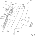
- the adjustment element is designed as an eccentric adjustment element 30a ( Fig.2 and Fig.3 ).
- the backrest 14a By means of the adjustment element 30a, the backrest 14a can be aligned to the support unit 12a at three different backrest adjustment angles.
- the adjustment element 30a is designed as a round disk.
- the adjustment element 30a has a coupling element 32a arranged eccentrically to the disk.
- the coupling element 32a is designed as a bolt.
- the adjustment element 30a is rotatably mounted.
- the adjustment element 30a has a rotation axis not shown in detail.
- the adjustment element 30a is arranged partially in the backrest 14a.
- the adjustment element 30a is coupled to the backrest 14a.
- the adjustment element 30a is provided for setting a backrest adjustment angle.
- the connection module 28a has three connecting elements 34a, 36a, 38a ( Fig.4 ). Using the three connecting elements 34a, 36a, 38a, the backrest 14a can be fixed to the support unit 12a at three different backrest angles. The three connecting elements 34a, 36a, 38a can be mounted without the need for new approval. The three connecting elements 34a, 36a, 38a can be exchanged without the need for new approval. The three connecting elements 34a, 36a, 38a are interchangeable with one another, whereby no new approval of the aircraft seat 24a is necessary. The three connecting elements 34a, 36a, 38a are formed from spatially separable elements. In the assembled and ready-to-fly aircraft seat 24a, only one connecting element 34a, 36a, 38a is mounted for each connecting module 28a.
- a backrest adjustment angle can be adjusted by means of the adjustment element 30a designed as an eccentric adjustment element or the three connecting elements 34a, 36a, 38a.
- the connection module 28a has at least one adjustment element 30a or at least two connecting elements 34a, 36a, 38a.
- the connection module 28a has the first connection element 34a ( Fig.4 ).
- the first connecting element 34a is designed as a plate.
- the first connecting element 34a is designed as a single, separate component.
- the first connecting element 34a is made of a metallic material, in particular a sheet metal.
- the first connecting element 34a has two connecting points 40a, 42a.
- the first connecting element 34a has a first connecting point 40a, via which the first connecting element 34a can be firmly coupled to the support unit 12a.
- the first connecting element 34a has a second connection point 42a, via which the first connecting element 34a can be firmly coupled to the backrest 14a.
- the first connection point 40a of the first connecting element 34a is designed as a through hole.
- the second connection point 42a of the first connecting element 34a is designed as a through hole.
- the first connecting element 34a has a first destruction point 44a.
- the first destruction point 44a is designed as a constriction.
- the support unit 12a can also be coupled to the second connection point 42a of the first connecting element 34a and the backrest 14a can also be coupled to the first connection point 40a of the first connecting element 34a.
- the connection module 28a has the second connection element 36a ( Fig.4 ).
- the second connecting element 36a is designed as a plate.
- the second connecting element 36a is designed as a single, separate component.
- the second connecting element 36a is made of a metallic material, in particular a sheet metal.
- the second connecting element 36a has two connection points 46a, 48a.
- the second connecting element 36a has a first connection point 46a, via which the second connecting element 36a can be firmly coupled to the support unit 12a.
- the second connecting element 36a has a second connection point 48a, via which the second connecting element 36a can be firmly coupled to the backrest 14a.
- the first connection point 46a of the second connecting element 36a is designed as a through hole.
- the second connection point 48a of the second connecting element 36a is designed as a through hole.
- the second connecting element 36a has a second destruction point 50a.
- the second destruction point 50a is designed as a constriction.
- the support unit 12a can also be coupled to the second connection point 48a of the second connection element 36a and the backrest 14a can also be coupled to the first connection point 46a of the second connection element 36a.
- the connection module 28a has the third connection element 38a ( Fig.4 ).
- the third connecting element 38a is designed as a plate.
- the third connecting element 38a is designed as a single, separate component.
- the third connecting element 38a is made of a metallic material, in particular a Sheet metal.
- the third connecting element 38a has two connection points 52a, 54a.
- the third connecting element 38a has a first connection point 52a, via which the third connecting element 38a can be firmly coupled to the support unit 12a.
- the third connecting element 38a has a second connection point 54a, via which the third connecting element 38a can be firmly coupled to the backrest 14a.
- the first connection point 52a of the third connecting element 38a is designed as a through hole.
- the second connection point 54a of the third connecting element 38a is designed as a through hole.
- the third connecting element 38a has a third destruction point 56a.
- the third destruction point 56a is designed as a constriction.
- the support unit 12a can also be coupled to the second connection point 52a of the third connection element 38a and the backrest 14a can also be coupled to the first connection point 54a of the third connection element 38a.
- a first distance 58a between the first connection point 40a and the second connection point 42a of the first connection element 34a differs from a second distance 60a between the first connection point 46a and the second connection point 48a of the second connection element 36a ( Fig.4 ).
- the second distance 60a between the first connection point 46a and the second connection point 48a of the second connection element 36a differs from a third distance 62a between the first connection point 52a and the second connection point 54a of the third connection element 38a.
- the third distance 62a between the first connection point 52a and the second connection point 54a of the third connection element 38a differs from the first distance 58a between the first connection point 40a and the second connection point 42a of the first connection element 34a.
- the first distance 58a, the second distance 60a and the third distance 62a are provided to set three different backrest adjustment angles.
- the first distance 58a is provided to set the standard position 16a.
- the second distance 60a is provided to set the comfort position 18a.
- the third distance 62a is intended to adjust the upright position 20a.
- the assembly kit 10a has a securing element 64a ( Fig.2 and Fig.3 ).
- the safety element 64a is in case of failure of at least one of the Connecting elements 34a, 36a, 38a are provided in the event of an overload to limit a movement of the backrest 14a to a maximum pivoting not shown in detail.
- the securing element 64a is designed as a plate.
- the securing element 64a is made of a metallic material, in particular a sheet metal.
- the securing element 64a has a guide groove 66a.
- the connecting module has a bolt 68a.
- the guide groove 66a is provided to guide the bolt 68a which is firmly connected to the support unit 12a.
- the seat divider 84a comprises a connecting element 90a ( Fig.3 ).
- the connecting element 90a is intended for coupling with the backrest 14a.
- the bolt 68a has a thread at its front end ( Fig.2 ).
- the bolt 68b is intended to be screwed into the connection element 90a.
- the seat divider 84a comprises a further connection element 92a.
- the further connection element 92a is intended to be coupled to a further backrest, not shown in detail.
- the safety element 64a has a delay element 70a ( Fig.2 ).
- the delay element 70a is at least intended to convert a kinetic energy of the backrest 14a into a deformation energy.
- the delay element 70a is designed as a constriction of the guide groove 66a.
- the delay element 70a is designed in one piece with the guide groove 66a.
- the delay element 70a narrows the guide groove 66a up to the maximum pivoting.
- the delay element 70a is intended to plastically deform the securing element 64a by a kinetic energy of the backrest 14a.
- the bolt 68a guided in the guide groove 66a is intended to press the delay element 70a apart.
- the assembly kit 10a has an attachment part 72a pivotably mounted on the backrest 14a ( Fig.1 ).
- the attachment part 72a is designed as a table unit.
- the assembly kit 10a has an adjustment unit 74a.
- the adjustment unit 74a By means of the adjustment unit 74a, the attachment part 72a can be aligned in a position of use at three different angles to the backrest 14a.
- the adjustment unit 74a comprises several grub screws (not shown in detail).
- the aircraft seat 24a comprises exactly one connecting element 34a ( Fig.2 and Fig.3 ).
- the aircraft seat 24a is mounted in the standard position 16a.
- the backrest adjustment angle of the standard position 16a is 100 degrees in the present case.
- the connecting elements 36a, 38a contained in the assembly kit 10a are not mounted in the aircraft seat 24a in the present case.
- the aircraft seat 24a is approved with the connecting element 34a.
- the aircraft seat 24a is approved in the standard position 16a.
- a different backrest adjustment angle can be provided with each connecting element 34a, 36a, 38a.
- the connecting element 36a is intended to set the comfort position 18a.
- the backrest adjustment angle of the comfort position is 3 degrees greater than the backrest adjustment angle of the standard position 16a.
- the connecting element 38a is intended to set the upright position 20a.
- the backrest adjustment angle of the upright position 20a is 3 degrees smaller than the backrest adjustment angle of the standard position 16a.
- the comfort position 18a and the upright position 20a have an angle difference of 6 degrees. This design allows the aircraft seat 24a with a backrest 14a that is not adjustable in the assembled and ready-to-fly state to have different backrest adjustment angles without the need for new approval, in particular in the standard position 16a, the comfort position 18a and the upright position 20a.
- an assembly kit according to the invention is shown in a second embodiment.
- An aircraft seat is shown in the Figures 5 and 6 not shown in detail.
- the assembly kit 10b comprises a support unit 12b.
- the support unit 12b has at least one seat divider 84b.
- the seat divider 84a is arranged on a right-hand side of the aircraft seat, viewed in a seating direction not shown in detail.
- the assembly kit 10b comprises a backrest 14b.
- the backrest 14b has a piping 88b.
- the backrest 14b forms a backrest surface not shown in detail.
- the backrest 14b is aligned with the support unit 12b at a backrest adjustment angle not shown in detail.
- the backrest 14b is not adjustable in the assembled and ready-to-fly state.
- the backrest 14b has a standard position, a comfort position or an upright position in the assembled and ready-to-fly state.
- the backrest 14b In the assembled and ready-to-fly state, the backrest 14b is firmly coupled to the support unit 12b.
- the backrest 14b In the assembled and ready-to-fly state, the backrest 14b is firmly coupled to the seat divider 84b and another seat divider, not shown in detail.
- the assembly kit 10b comprises two connection modules 28b.
- connection module 28b is arranged on a right-hand side of the backrest 14b, viewed in the direction of the seat.
- a further connection module is arranged on a left-hand side of the backrest 14b, viewed in the direction of the seat.
- the further connection module is in particular designed to be mirrored to the connection module 28b.
- the connecting module 28b has an adjustment element 30b.
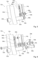
- the adjustment element 30b is designed as an eccentric adjustment element ( Fig. 5 and Fig. 6 ).
- the adjustment element 30b is designed as a round disk.
- the adjustment element 30b has a coupling element 32b arranged eccentrically to the disk.
- the coupling element 32b is designed as a bolt.
- the adjustment element 30b is rotatably mounted.
- the adjustment element 30b has a rotation axis not shown in detail.
- the adjustment element 30b is arranged partially in the backrest 14b.
- the adjustment element 30b is coupled to the backrest 14b.
- the adjustment element 30b is provided for setting a backrest adjustment angle.
- the backrest 14b has a Support element 94b.
- the adjustment element 30b is supported against the backrest 14b by means of the support element 94b.
- the support element 94b has a groove 96b which is provided for adjusting the adjustment element 30b. In the assembled and ready-to-fly state, the support element 94b is firmly connected to the backrest 14b by means of a rivet 98b through the groove 96b.
- the connection module 28b has three connection elements 34b, whereby only the first connection element 34b is in the Figures 5 and 6 is shown.
- the connection module 28b has the first connection element 34b.
- the connection module 28b has two further connection elements, not shown in detail.
- the three connection elements 34b can correspond to the three connection elements 34a, 36a, 38a from the first embodiment.
- the backrest 14b can be fixed to the support unit 12b at three different backrest adjustment angles.
- the three connection elements 34b can be installed without the need for new approval.
- the three connection elements 34b can be exchanged without the need for new approval.
- the three connection elements 34b are interchangeable with one another, whereby no new approval of the aircraft seat is necessary.
- connection elements 34b are formed from spatially separable elements. In the assembled and ready-to-fly aircraft seat, only one connection element 34b is mounted for each connection module 28b. In the assembled and ready-to-fly state, the aircraft seat comprises exactly one connecting element 34b for each connecting module 28b. The two further connecting elements contained in the assembly kit 10b, which are not shown in detail, are not mounted in the aircraft seat in the present case.
- a backrest adjustment angle can be adjusted by means of the adjustment element 30b or the three connecting elements 34b.
- the connecting module 28b has at least one adjustment element 30b or at least two connecting elements 34b.
- the first connecting element 34b is designed as a plate.
- the first connecting element 34b is designed as a single, separate component.
- the first connecting element 34b is made of a metallic material, in particular a sheet metal.
- the first connecting element 34b has two connecting points 40b, 42b.
- the first connecting element 34b has a first connecting point 40b, via which the first connecting element 34b can be firmly coupled to the support unit 12b.
- the first connecting element 34b has a second connection point 42b, via which the first connecting element 34b can be firmly coupled to the backrest 14b.
- the first connection point 40b of the first connecting element 34b is designed as a through hole.
- the second connection point 42b of the first connecting element 34b is designed as a through hole.
- the first connecting element 34b has a first destruction point 44b.
- the first destruction point 44b is designed as a constriction.
- the support unit 12b can also be coupled to the second connection point 42b of the first connecting element 34b and the backrest 14b can also be coupled to the first connection point 40b of the first connecting element 34b.
- the connecting element 34b is partially arranged in a frame of the backrest 14b.
- the seat divider 84b comprises a connecting element 90b ( Fig. 5 and Fig. 6 ).
- the connection element 90b is intended for coupling to the backrest 14b.
- the connection module has a bolt 68b.
- the bolt 68b is intended to be inserted into the connection element 90b.
- the bolt 68b is secured in an assembled and ready-to-fly state with a dowel pin (not shown in detail). In principle, the bolt 68b could also be screwed into the connection element 90b.
- the seat divider 84b comprises a further connection element 92b.
- the further connection element 92b is intended for coupling to a further backrest (not shown in detail).
- the assembly kit 10b in particular does not have a securing element.
- an assembly kit according to the invention is only partially shown.
- An aircraft seat is shown in the Figures 7 to 9 not shown in detail.
- the assembly kit has at least one partially shown connecting module.
- the assembly kit includes a support unit not shown in detail.
- the assembly kit includes a not shown in detail Backrest.
- the backrest is aligned with the support unit at a backrest adjustment angle that is not shown in detail.
- the backrest is not adjustable when assembled and ready to fly. When assembled and ready to fly, the backrest has a standard position, a comfort position or an upright position. When assembled and ready to fly, the assembly kit forms the aircraft seat.
- the aircraft seat is manufactured using the assembly kit according to the invention.
- the Figure 7 shows two connecting elements 34c, 36c in a third embodiment.
- the connecting module has the first connecting element 34c.
- the connecting module has the second connecting element 36c.
- the two connecting elements 34c, 36c are formed in one piece as a single component.
- the two connecting elements 34c, 36c can be mounted in a first mounting position and a second mounting position. Both connecting elements 34c, 36c are mounted in the assembled and ready-to-fly aircraft seat.
- the two connecting elements 34c, 36c are formed as a plate.
- the two connecting elements 34c, 36c are made of a metallic material, in particular a sheet metal.
- the two connecting elements 34c, 36c can be mounted without the need for new approval.
- the two connecting elements 34c, 36c can be exchanged without the need for new approval.
- the two connecting elements 34c, 36c can be mounted in two different mounting positions, whereby no new approval of the aircraft seat is necessary for either mounting position.
- the first connecting element 34c has two connecting points 40c, 42c.
- the first connecting element 34c has a first connecting point 40c, via which the first connecting element 34c can be firmly coupled to the support unit.
- the first connecting element 34c has a second connecting point 42c, via which the first connecting element 34c can be firmly coupled to the backrest.
- the first connecting point 40c of the first connecting element 34c is designed as a through hole.
- the second connecting point 42c of the first connecting element 34c is designed as a through hole.
- the first connecting element 34c has a first Destruction point 44c.
- the first destruction point 44c is designed as a constriction.
- the second connecting element 36c has two connection points 46c, 48c.
- the second connecting element 36c has a first connection point 46c, via which the second connecting element 36c can be firmly coupled to the support unit.
- the first connection point 46c of the second connecting element 36c is designed as the first connection point 40c of the first connecting element 34c.
- the second connecting element 36c has a second connection point 48c, via which the second connecting element 36c can be firmly coupled to the backrest.
- the second connection point 48c of the second connecting element 36c is designed as a through hole.
- the second connecting element 36c has a second destruction point 50c.
- the second destruction point 50c is designed as the first destruction point 44c.
- the Figure 8 shows three connecting elements 34d, 36d, 38d in a fourth embodiment.
- the connecting module has the first connecting element 34d.
- the connecting module has the second connecting element 36d.
- the connecting module has the third connecting element 38d.
- the three connecting elements 34d, 36d, 38d are integrally formed as a single component.
- the three connecting elements 34d, 36d, 38d can be mounted in a first assembly position, in a second assembly position and in a third assembly position. All three connecting elements 34d, 36d, 38d are mounted in the assembled and ready-to-fly aircraft seat.
- the three connecting elements 34d, 36d, 38d are designed as a plate.
- the three connecting elements 34d, 36d, 38d are made of a metallic material, in particular a sheet metal.
- the backrest can be adjusted in three different Backrest adjustment angles can be fixed to the stand unit.
- the three connecting elements 34d, 36d, 38d can be installed without the need for new approval.
- the three connecting elements 34d, 36d, 38d can be exchanged without the need for new approval.
- the three connecting elements 34d, 36d, 38d can be installed in three different mounting positions, whereby no new approval of the aircraft seat is necessary for the mounting positions.
- the first connecting element 34d has two connection points 40d, 42d.
- the first connecting element 34d has a first connection point 40d, via which the first connecting element 34d can be firmly coupled to the support unit.
- the first connecting element 34d has a second connection point 42d, via which the first connecting element 34d can be firmly coupled to the backrest.
- the first connection point 40d of the first connecting element 34d is designed as a through hole.
- the second connection point 42d of the first connecting element 34d is designed as a through hole.
- the second connecting element 36d has two connection points 46d, 48d.
- the second connecting element 36d has a first connection point 46d, via which the second connecting element 36d can be firmly coupled to the support unit.
- the first connection point 46d of the second connecting element 36d is designed as the first connection point 40d of the first connecting element 34d.
- the second connecting element 36d has a second connection point 48d, via which the second connecting element 36d can be firmly coupled to the backrest.
- the second connection point 48d of the second connecting element 36d is designed as a through hole.
- the third connecting element 38d has two connection points 52d, 54d.
- the third connecting element 38d has a first connection point 52d, via which the third connecting element 38d can be firmly coupled to the support unit.
- the first connection point 52d of the third connecting element 38d is designed as the first connection point 40d of the first connecting element 34d.
- the third connecting element 38d has a second connection point 54d, via which the third connecting element 38d can be firmly coupled to the backrest.
- the second connection point 54d of the third connecting element 38d is designed as a through hole.
- a first distance 58d between the first connection point 40d and the second connection point 42d of the first connection element 34d differs from a second distance 60d between the first connection point 46d and the second connection point 48d of the second connection element 36d.
- the second distance 60d between the first connection point 46d and the second connection point 48d of the second connection element 36d differs from a third distance 62d between the first connection point 52d and the second connection point 54d of the third connection element 38d.
- the third distance 62d between the first connection point 52d and the second connection point 54d of the third connection element 38d differs from the first distance 58d between the first connection point 40d and the second connection point 42d of the first connection element 34d.
- the first distance 58d, the second distance 60d and the third distance 62d are intended to set three different backrest angles.
- the first distance 58d is intended to set the standard position.
- the second distance 60d is intended to set the comfort position.
- the third distance 62d is intended to set the upright position.
- the Figure 9 shows three connecting elements 34e, 36e, 38e in a fifth embodiment.
- the connecting module has the first connecting element 34e.
- the connecting module has the second connecting element 36e.
- the connecting module has the third connecting element 38e.
- the three connecting elements 34e, 36e, 38e are formed in one piece as a single component.
- the three connecting elements 34e, 36e, 38e can be mounted in a first assembly position, in a second assembly position and in a third assembly position. All three connecting elements 34e, 36e, 38e are mounted in the assembled and ready-to-fly aircraft seat.
- the three connecting elements 34e, 36e, 38e are formed as a plate.
- the three connecting elements 34e, 36e, 38e are made of a metallic material, in particular a sheet metal.
- the backrest can be fixed to the support unit at three different backrest angles.
- the three connecting elements 34e, 36e, 38e can be mounted without the need for new registration.
- the three connecting elements 34e, 36e, 38e can be exchanged without the need for new registration.
- the three connecting elements 34e, 36e, 38e can be mounted in three different positions. can be mounted, whereby no new approval of the aircraft seat is necessary for the mounting positions.
- the first connecting element 34e has two connection points 40e, 42e.
- the first connecting element 34e has a first connection point 40e, via which the first connecting element 34e can be firmly coupled to the support unit.
- the first connecting element 34e has a second connection point 42e, via which the first connecting element 34e can be firmly coupled to the backrest.
- the first connection point 40e of the first connecting element 34e is designed as a through hole.
- the second connection point 42e of the first connecting element 34e is designed as a through hole.
- the second connecting element 36e has two connection points 46e, 48e.
- the second connecting element 36e has a first connection point 46e, via which the second connecting element 36e can be firmly coupled to the support unit.
- the first connection point 46e of the second connecting element 36e is designed as a through hole.
- the second connecting element 36e has a second connection point 48e, via which the second connecting element 36e can be firmly coupled to the backrest.
- the second connection point 48e of the second connecting element 36e is designed as the second connection point 42e of the first connecting element 34e.
- the third connecting element 38e has two connection points 52e, 54e.
- the third connecting element 38e has a first connection point 52e, via which the third connecting element 38e can be firmly coupled to the support unit.
- the first connection point 52e of the third connecting element 38e is designed as the first connection point 46e of the second connecting element 36e.
- the third connecting element 38e has a second connection point 54e, via which the third connecting element 38e can be firmly coupled to the backrest.
- the second connection point 54e of the third connecting element 38e is designed as a through hole.
- a first distance 58e between the first connection point 40e and the second connection point 42e of the first connection element 34e differs from a second distance 60e between the first connection point 46e and the second connection point 48e of the second connection element 36e.
- the second distance 60e between the first connection point 46e and the second connection point 48e of the second connection element 36e differs from a third distance 62e between the first connection point 52e and the second connection point 54e of the third connection element 38e.
- the third distance 62e between the first connection point 52e and the second connection point 54e of the third connection element 38e differs from the first distance 58e between the first connection point 40e and the second connection point 42e of the first connection element 34e.
- the first distance 58e, the second distance 60e and the third distance 62e are intended to set three different backrest adjustment angles.
- the first distance 58e is intended to set the standard position.
- the second distance 60e is intended to set the comfort position.
- the third distance 62e is intended to set the upright position.
Landscapes
- Engineering & Computer Science (AREA)
- Aviation & Aerospace Engineering (AREA)
- Chairs For Special Purposes, Such As Reclining Chairs (AREA)
- Seats For Vehicles (AREA)
Claims (15)
- Kit de montage pour un siège d'avion (24a),avec au moins une unité de montant (12a ; 12b),avec au moins un dossier (14a ; 14b) couplé fixement à l'unité de montant (12a ; 12b) en état monté et prêt à voler,et avec au moins un module de raccordement (28a ; 28b), par le biais duquel le dossier (14a ; 14b) est orienté rigidement dans une position par rapport à l'unité de montant (12a ; 12b) en état monté et prêt à voler,caractérisé en ce que le module de raccordement (28a ; 28b) présente au moins deux éléments de raccordement (34a, 36a, 38a ; 34b ; 34c, 36c ; 34d, 36d, 38d ; 34e, 36e, 38e) moyennant lesquels le dossier (14a) peut être monté dans au moins deux angles-réglage de dossier différents fixement par rapport à l'unité de montant (12a), où les au moins deux éléments de raccordement (34a, 36a, 38a ; 34b ; 34c, 36c ; 34d, 36d, 38d ; 34e, 36e, 38e) peuvent être montés sans nouvelle autorisation, le terme « sans nouvelle autorisation » devant signifier que lors d'une modification de l'angle-réglage de dossier par +3 degrés ou -3 degrés à partir d'une position standard du dossier (14a ; 14b), en considération de la tolérance de fabrication de +1 degré et de -1 degré, aucune nouvelle autorisation n'est nécessaire pour un siège d'avion (24a) autorisé,où un angle de réglage de dossier différent peut être pourvu avec chaque élément de raccordement (34a, 36a, 38a ; 34b ; 34c, 36c ; 34d, 36d, 38d ; 34e, 36e, 38e) et le dossier (14a ; 14b) n'est pas réglable en état monté et prêt à voler.
- Kit de montage selon la revendication 1,
caractérisé en ce que les au moins deux éléments de raccordement (34c, 36c ; 34d, 36d, 38d ; 34e, 36e, 38e) sont réalisés intégralement et peuvent être montés au moins dans une première position de montage et une deuxième position de montage. - Kit de montage selon la revendication 1,
caractérisé en ce que les au moins deux éléments de raccordement (34a, 36a, 38a ; 34b) sont formés par des éléments séparables dans l'espace. - Kit de montage selon la revendication 1,
caractérisé en ce que le module de raccordement (28a ; 28b) comprend au moins un élément de réglage (30a, 30b), par le biais duquel le dossier (14a ; 14b) peut sans nouvelle autorisation être orienté respectivement dans au moins deux angles-réglage de dossier différents par rapport à l'unité de montant (12a ; 12b). - Kit de montage selon la revendication 4,
caractérisé en ce que l'au moins un élément de réglage (30a ; 30b) est réalisé sous forme d'élément de réglage excentrique. - Kit de montage selon l'une des revendications précédentes, caractérisé en ce qu'au moins l'un des éléments de raccordement (34a, 36a, 38a ; 34b ; 34c, 36c ; 34d, 36d, 38d ; 34e, 36e, 38e) est réalisé sous forme de plaque.
- Kit de montage selon l'une des revendications précédentes, caractérisé en ce qu'au moins l'un des éléments de raccordement (34a, 36a, 38a ; 34b ; 34c, 36c ; 34d, 36d, 38d ; 34e, 36e, 38e) présente au moins deux points de raccordement (40a, 42a, 46a, 48a, 52a, 54a ; 40b, 42b ; 40c, 42c, 46c, 48c ; 40d, 42d, 46d, 48d, 52d, 54d ; 40e, 42e, 46e, 48e, 52e, 54e).
- Kit de montage au moins selon la revendication 7,
caractérisé en ce qu'au moins l'un des éléments de raccordement (34a, 36a, 38a ; 34b ; 34c, 36c ; 34d, 36d, 38d ; 34e, 36e, 38e) présente au moins un premier point de raccordement (40a, 46a, 52a ; 40b ; 40c, 46c ; 40d, 46d, 52d ; 40e, 46e, 52e), par le biais duquel l'au moins un élément de raccordement (34a, 36a, 38a ; 34b ; 34c, 36c ; 34d, 36d, 38d ; 34e, 36e, 38e) peut être couplé fixement à l'unité de montant (12a ; 12b), et présente au moins un deuxième point de raccordement (42a, 48a, 54a ; 42b ; 42c, 48c ; 42d, 48d, 54d ; 42e, 48e, 54e), par le biais duquel l'au moins un élément de raccordement (34a, 36a, 38a ; 34b ; 34c, 36c ; 34d, 36d, 38d ; 34e, 36e, 38e) peut être couplé fixement au dossier (14a ; 14b). - Kit de montage au moins selon la revendication 8,
caractérisé en ce qu'une première distance (58a ; 58c ; 58d ; 58e) entre un premier point de raccordement (40a ; 40b ; 40c ; 40d ; 40e) et un deuxième point de raccordement (42a ; 42b ; 42c ; 42d ; 42e) d'un premier élément de raccordement (34a ; 34b ; 34c ; 34d ; 34e) diffère d'une deuxième distance (60a ; 60c ; 60d ; 60e) entre un premier point de raccordement (46a ; 46c ; 46d ; 46e) et un deuxième point de raccordement (48a ; 48c ; 48d ; 48e) d'un au moins deuxième élément de raccordement (36a ; 36c ; 36d ; 36e). - Kit de montage selon l'une des revendications précédentes, caractérisé en ce qu'au moins l'un des éléments de raccordement (34a, 36a, 38a ; 34b ; 34c, 36c ; 34d, 36d, 38d ; 34e, 36e, 38e) présente au moins un point de destruction (44a, 50a, 56a ; 44b ; 44c, 50c).
- Kit de montage selon l'une des revendications précédentes, caractérisé par au moins un élément de sécurité (64a) qui est conçu, en cas de défaillance d'au moins un des éléments de raccordement (34a, 36a, 38a) en cas de surcharge, pour limiter un mouvement du dossier (14a) à un pivotement maximal.
- Kit de montage au moins selon la revendication 11,
caractérisé en ce que l'au moins un élément de sécurisation (64a) comprend au moins un élément de ralentissement (70a) qui est au moins prévu pour convertir une énergie de mouvement du dossier (14a). - Kit de montage selon l'une des revendications précédentes,
caractérisé par au moins une pièce rapportée (72a) supportée de manière pivotable sur le dossier (14a) et au moins une unité de réglage (74a) par le biais de laquelle l'au moins une pièce rapportée (72a) peut dans une position d'utilisation être orientée respectivement dans au moins deux angles différents par rapport au dossier (14a). - Siège d'avion (24a) fabriqué au moyen d'un kit de montage selon l'une des revendications précédentes.
- Procédé de montage d'un siège d'avion (24a) avec un kit de montage selon l'une des revendications précédentes 1 à 13.
Applications Claiming Priority (2)
| Application Number | Priority Date | Filing Date | Title |
|---|---|---|---|
| DE102018133538.5A DE102018133538A1 (de) | 2018-12-21 | 2018-12-21 | Montagebausatz für einen Flugzeugsitz |
| PCT/EP2019/086528 WO2020127872A1 (fr) | 2018-12-21 | 2019-12-20 | Kit de montage pour siège d'avion |
Publications (2)
| Publication Number | Publication Date |
|---|---|
| EP3898415A1 EP3898415A1 (fr) | 2021-10-27 |
| EP3898415B1 true EP3898415B1 (fr) | 2024-09-11 |
Family
ID=69157800
Family Applications (1)
| Application Number | Title | Priority Date | Filing Date |
|---|---|---|---|
| EP19835397.1A Active EP3898415B1 (fr) | 2018-12-21 | 2019-12-20 | Kit de montage pour siège d'avion |
Country Status (5)
| Country | Link |
|---|---|
| US (1) | US12195185B2 (fr) |
| EP (1) | EP3898415B1 (fr) |
| CN (1) | CN113453984B (fr) |
| DE (1) | DE102018133538A1 (fr) |
| WO (1) | WO2020127872A1 (fr) |
Families Citing this family (5)
| Publication number | Priority date | Publication date | Assignee | Title |
|---|---|---|---|---|
| US12030415B2 (en) * | 2019-07-31 | 2024-07-09 | Safran Seats Usa Llc | Vertically adjustable tray table |
| US11845558B2 (en) * | 2021-08-19 | 2023-12-19 | Recaro Aircraft Seating Gmbh & Co. Kg | Aircraft passenger seat device with a connection unit comprising an impact safety device |
| EP4289742A1 (fr) * | 2022-06-07 | 2023-12-13 | Acro Aircraft Seating Limited | Dossier de siège comprenant un dispositif d'absorption d'énergie |
| DE102023107192A1 (de) * | 2023-03-22 | 2024-09-26 | Recaro Aircraft Seating Gmbh & Co. Kg | Flugzeugsitzvorrichtung |
| DE102024116988A1 (de) * | 2024-06-17 | 2025-12-18 | Recaro Aircraft Seating Gmbh & Co. Kg | Flugzeugsitzvorrichtung |
Citations (1)
| Publication number | Priority date | Publication date | Assignee | Title |
|---|---|---|---|---|
| DE19724763C2 (de) * | 1997-06-12 | 2003-04-03 | Recaro Aircraft Seating Gmbh | Fahrzeugsitz, insbesondere Fluggastsitz |
Family Cites Families (13)
| Publication number | Priority date | Publication date | Assignee | Title |
|---|---|---|---|---|
| US2518860A (en) * | 1946-10-31 | 1950-08-15 | Max T Blue | Aircraft passenger chair |
| US2513860A (en) | 1949-08-08 | 1950-07-04 | Harry L Gordon | Antifriction roller bearing |
| FR2629789B1 (fr) * | 1988-04-08 | 1992-02-21 | Sicma Aero Seat | Structure de siege d'appareil de transport aerien en commun et siege comportant une telle structure |
| DE102005022694B4 (de) * | 2005-05-18 | 2008-09-04 | Recaro Aircraft Seating Gmbh & Co. Kg | Sitz |
| US8272694B2 (en) | 2008-07-08 | 2012-09-25 | B/E Aerospace, Inc. | Articulating passenger seat |
| FR2948326B1 (fr) * | 2009-07-24 | 2011-08-26 | Faurecia Sieges D Automobiles | Siege, notamment siege de type aviation, comportant une tablette de travail relevable contre la face arriere du dossier |
| DE102013016951A1 (de) * | 2013-10-14 | 2015-04-16 | Recaro Aircraft Seating Gmbh & Co. Kg | Flugzeugsitzvorrichtung |
| DE102014226642A1 (de) * | 2014-12-19 | 2016-06-23 | Brose Fahrzeugteile Gmbh & Co. Kg, Coburg | Fahrzeugsitzbaugruppe mit Rückstelleinrichtung |
| US9719768B2 (en) * | 2015-07-21 | 2017-08-01 | Honda Motor Co., Ltd. | Methods and apparatus for aligning vehicle components |
| DE102015226664A1 (de) * | 2015-12-23 | 2017-06-29 | Airbus Operations Gmbh | Passagiersitz mit einem verschiebbaren Sitzelement und Passagierkabinenbereich |
| DE102015122830A1 (de) | 2015-12-23 | 2017-06-29 | Recaro Aircraft Seating Gmbh & Co. Kg | Flugzeugsitzvorrichtung |
| EP3323725B1 (fr) * | 2016-11-16 | 2020-08-12 | Airbus Operations GmbH | Kit de siège d'aéronef, agencement de cabine et de siège d'aéronef avec différents types d'adaptateurs de rail de siège |
| DE102016224625A1 (de) * | 2016-12-09 | 2018-06-14 | Brose Fahrzeugteile Gmbh & Co. Kg, Coburg | Fahrzeugsitz mit Sperrmechanimus zur Sperrung eines zumindest abschnittsweise absenkbaren Polsterträgers bei einer Verstellung einer Rückenlehne |
-
2018
- 2018-12-21 DE DE102018133538.5A patent/DE102018133538A1/de not_active Withdrawn
-
2019
- 2019-12-20 US US17/416,224 patent/US12195185B2/en active Active
- 2019-12-20 CN CN201980092413.8A patent/CN113453984B/zh active Active
- 2019-12-20 EP EP19835397.1A patent/EP3898415B1/fr active Active
- 2019-12-20 WO PCT/EP2019/086528 patent/WO2020127872A1/fr not_active Ceased
Patent Citations (1)
| Publication number | Priority date | Publication date | Assignee | Title |
|---|---|---|---|---|
| DE19724763C2 (de) * | 1997-06-12 | 2003-04-03 | Recaro Aircraft Seating Gmbh | Fahrzeugsitz, insbesondere Fluggastsitz |
Also Published As
| Publication number | Publication date |
|---|---|
| DE102018133538A1 (de) | 2020-06-25 |
| CN113453984B (zh) | 2024-10-01 |
| US20220041286A1 (en) | 2022-02-10 |
| CN113453984A (zh) | 2021-09-28 |
| US12195185B2 (en) | 2025-01-14 |
| WO2020127872A1 (fr) | 2020-06-25 |
| EP3898415A1 (fr) | 2021-10-27 |
Similar Documents
| Publication | Publication Date | Title |
|---|---|---|
| EP3898415B1 (fr) | Kit de montage pour siège d'avion | |
| DE69305009T2 (de) | Vorrichtung zur Blockierung eines Fahrzeugsitzes während eines Aufpralls | |
| EP2242688B1 (fr) | Ensemble de fixation mobile pour châssis de siège dans un avion | |
| WO1988001967A1 (fr) | Siege pivotant, notamment pour un membre de l'equipage d'un avion | |
| EP3359416B1 (fr) | Appui-tête d'un siège de véhicule | |
| WO2016120143A1 (fr) | Siège de véhicule | |
| DE102015223485B4 (de) | Höheneinsteller für einen fahrzeugsitz, fahrzeugsitz | |
| EP2765025A1 (fr) | Siège de véhicule | |
| DE102017200093B4 (de) | Modulare Rückenlehnen-Fernbedienung und Verfahren zum Montieren eines Fahrzeugrücksitzes | |
| DE102019213143B4 (de) | Fahrzeugsitz-anordnung und vorspannungsmechanismus für eine fahrzeugsitz-anordnung, sowie verfahren zum installieren einer fahrzeugsitz-anordnung | |
| WO1987001355A1 (fr) | Siege et agencement de celui-ci pour passager d'un avion | |
| DE10206299A1 (de) | Beschlag für einen Fahrzeugsitz | |
| EP3083401B1 (fr) | Dispositif de support de siège d'avion | |
| DE19905295B4 (de) | Befestigungsstruktur für eine Fahrzeugsitz-Rückenlehne | |
| EP3956192A1 (fr) | Dispositif pour un véhicule sur rails, et véhicule sur rails | |
| WO2020035571A1 (fr) | Dispositif de fixation de siège d'avion | |
| DE102010054410A1 (de) | Lastkraftwagen | |
| DE69406157T2 (de) | Fahrzeugsitz und dessen Anwendung bei einem Rücksitz | |
| DE4239141A1 (en) | Bank of seats for helicopter - uses quick release pins to permit the removal of individual seats | |
| DE102020106034A1 (de) | Scharnier | |
| DE102012107817B4 (de) | Polsterträgerplatte für eine Sitztiefenverstellung | |
| DE102007050091A1 (de) | Fahrzeugsitz mit einem drehbaren Rückenteil | |
| DE19806904C1 (de) | Verriegelungsvorrichtung für eine klappbare Rückenlehne eines Kraftfahrzeugsitzes | |
| EP1814757A1 (fr) | Element structurel pour un siege, en particulier un siege de vehicule automobile, structure de siege pourvue de l'element structurel et siege pourvu de cet element structurel ou de la structure de siege | |
| DE102006026866B4 (de) | Kraftfahrzeugsitz |
Legal Events
| Date | Code | Title | Description |
|---|---|---|---|
| STAA | Information on the status of an ep patent application or granted ep patent |
Free format text: STATUS: UNKNOWN |
|
| STAA | Information on the status of an ep patent application or granted ep patent |
Free format text: STATUS: THE INTERNATIONAL PUBLICATION HAS BEEN MADE |
|
| PUAI | Public reference made under article 153(3) epc to a published international application that has entered the european phase |
Free format text: ORIGINAL CODE: 0009012 |
|
| STAA | Information on the status of an ep patent application or granted ep patent |
Free format text: STATUS: REQUEST FOR EXAMINATION WAS MADE |
|
| 17P | Request for examination filed |
Effective date: 20210708 |
|
| AK | Designated contracting states |
Kind code of ref document: A1 Designated state(s): AL AT BE BG CH CY CZ DE DK EE ES FI FR GB GR HR HU IE IS IT LI LT LU LV MC MK MT NL NO PL PT RO RS SE SI SK SM TR |
|
| DAV | Request for validation of the european patent (deleted) | ||
| DAX | Request for extension of the european patent (deleted) | ||
| STAA | Information on the status of an ep patent application or granted ep patent |
Free format text: STATUS: EXAMINATION IS IN PROGRESS |
|
| 17Q | First examination report despatched |
Effective date: 20230320 |
|
| GRAP | Despatch of communication of intention to grant a patent |
Free format text: ORIGINAL CODE: EPIDOSNIGR1 |
|
| STAA | Information on the status of an ep patent application or granted ep patent |
Free format text: STATUS: GRANT OF PATENT IS INTENDED |
|
| INTG | Intention to grant announced |
Effective date: 20240404 |
|
| GRAS | Grant fee paid |
Free format text: ORIGINAL CODE: EPIDOSNIGR3 |
|
| P01 | Opt-out of the competence of the unified patent court (upc) registered |
Free format text: CASE NUMBER: APP_39711/2024 Effective date: 20240703 |
|
| GRAA | (expected) grant |
Free format text: ORIGINAL CODE: 0009210 |
|
| STAA | Information on the status of an ep patent application or granted ep patent |
Free format text: STATUS: THE PATENT HAS BEEN GRANTED |
|
| AK | Designated contracting states |
Kind code of ref document: B1 Designated state(s): AL AT BE BG CH CY CZ DE DK EE ES FI FR GB GR HR HU IE IS IT LI LT LU LV MC MK MT NL NO PL PT RO RS SE SI SK SM TR |
|
| REG | Reference to a national code |
Ref country code: GB Ref legal event code: FG4D Free format text: NOT ENGLISH |
|
| REG | Reference to a national code |
Ref country code: CH Ref legal event code: EP |
|
| REG | Reference to a national code |
Ref country code: DE Ref legal event code: R096 Ref document number: 502019012129 Country of ref document: DE |
|
| REG | Reference to a national code |
Ref country code: IE Ref legal event code: FG4D Free format text: LANGUAGE OF EP DOCUMENT: GERMAN |
|
| REG | Reference to a national code |
Ref country code: LT Ref legal event code: MG9D |
|
| PG25 | Lapsed in a contracting state [announced via postgrant information from national office to epo] |
Ref country code: NO Free format text: LAPSE BECAUSE OF FAILURE TO SUBMIT A TRANSLATION OF THE DESCRIPTION OR TO PAY THE FEE WITHIN THE PRESCRIBED TIME-LIMIT Effective date: 20241211 |
|
| REG | Reference to a national code |
Ref country code: NL Ref legal event code: MP Effective date: 20240911 |
|
| PG25 | Lapsed in a contracting state [announced via postgrant information from national office to epo] |
Ref country code: GR Free format text: LAPSE BECAUSE OF FAILURE TO SUBMIT A TRANSLATION OF THE DESCRIPTION OR TO PAY THE FEE WITHIN THE PRESCRIBED TIME-LIMIT Effective date: 20241212 Ref country code: FI Free format text: LAPSE BECAUSE OF FAILURE TO SUBMIT A TRANSLATION OF THE DESCRIPTION OR TO PAY THE FEE WITHIN THE PRESCRIBED TIME-LIMIT Effective date: 20240911 |
|
| PG25 | Lapsed in a contracting state [announced via postgrant information from national office to epo] |
Ref country code: BG Free format text: LAPSE BECAUSE OF FAILURE TO SUBMIT A TRANSLATION OF THE DESCRIPTION OR TO PAY THE FEE WITHIN THE PRESCRIBED TIME-LIMIT Effective date: 20240911 |
|
| PG25 | Lapsed in a contracting state [announced via postgrant information from national office to epo] |
Ref country code: LV Free format text: LAPSE BECAUSE OF FAILURE TO SUBMIT A TRANSLATION OF THE DESCRIPTION OR TO PAY THE FEE WITHIN THE PRESCRIBED TIME-LIMIT Effective date: 20240911 |
|
| PG25 | Lapsed in a contracting state [announced via postgrant information from national office to epo] |
Ref country code: HR Free format text: LAPSE BECAUSE OF FAILURE TO SUBMIT A TRANSLATION OF THE DESCRIPTION OR TO PAY THE FEE WITHIN THE PRESCRIBED TIME-LIMIT Effective date: 20240911 |
|
| PG25 | Lapsed in a contracting state [announced via postgrant information from national office to epo] |
Ref country code: RS Free format text: LAPSE BECAUSE OF FAILURE TO SUBMIT A TRANSLATION OF THE DESCRIPTION OR TO PAY THE FEE WITHIN THE PRESCRIBED TIME-LIMIT Effective date: 20241211 Ref country code: ES Free format text: LAPSE BECAUSE OF FAILURE TO SUBMIT A TRANSLATION OF THE DESCRIPTION OR TO PAY THE FEE WITHIN THE PRESCRIBED TIME-LIMIT Effective date: 20240911 |
|
| PG25 | Lapsed in a contracting state [announced via postgrant information from national office to epo] |
Ref country code: RS Free format text: LAPSE BECAUSE OF FAILURE TO SUBMIT A TRANSLATION OF THE DESCRIPTION OR TO PAY THE FEE WITHIN THE PRESCRIBED TIME-LIMIT Effective date: 20241211 Ref country code: NO Free format text: LAPSE BECAUSE OF FAILURE TO SUBMIT A TRANSLATION OF THE DESCRIPTION OR TO PAY THE FEE WITHIN THE PRESCRIBED TIME-LIMIT Effective date: 20241211 Ref country code: LV Free format text: LAPSE BECAUSE OF FAILURE TO SUBMIT A TRANSLATION OF THE DESCRIPTION OR TO PAY THE FEE WITHIN THE PRESCRIBED TIME-LIMIT Effective date: 20240911 Ref country code: HR Free format text: LAPSE BECAUSE OF FAILURE TO SUBMIT A TRANSLATION OF THE DESCRIPTION OR TO PAY THE FEE WITHIN THE PRESCRIBED TIME-LIMIT Effective date: 20240911 Ref country code: GR Free format text: LAPSE BECAUSE OF FAILURE TO SUBMIT A TRANSLATION OF THE DESCRIPTION OR TO PAY THE FEE WITHIN THE PRESCRIBED TIME-LIMIT Effective date: 20241212 Ref country code: FI Free format text: LAPSE BECAUSE OF FAILURE TO SUBMIT A TRANSLATION OF THE DESCRIPTION OR TO PAY THE FEE WITHIN THE PRESCRIBED TIME-LIMIT Effective date: 20240911 Ref country code: ES Free format text: LAPSE BECAUSE OF FAILURE TO SUBMIT A TRANSLATION OF THE DESCRIPTION OR TO PAY THE FEE WITHIN THE PRESCRIBED TIME-LIMIT Effective date: 20240911 Ref country code: BG Free format text: LAPSE BECAUSE OF FAILURE TO SUBMIT A TRANSLATION OF THE DESCRIPTION OR TO PAY THE FEE WITHIN THE PRESCRIBED TIME-LIMIT Effective date: 20240911 |
|
| PG25 | Lapsed in a contracting state [announced via postgrant information from national office to epo] |
Ref country code: NL Free format text: LAPSE BECAUSE OF FAILURE TO SUBMIT A TRANSLATION OF THE DESCRIPTION OR TO PAY THE FEE WITHIN THE PRESCRIBED TIME-LIMIT Effective date: 20240911 |
|
| PG25 | Lapsed in a contracting state [announced via postgrant information from national office to epo] |
Ref country code: IS Free format text: LAPSE BECAUSE OF FAILURE TO SUBMIT A TRANSLATION OF THE DESCRIPTION OR TO PAY THE FEE WITHIN THE PRESCRIBED TIME-LIMIT Effective date: 20250111 Ref country code: PT Free format text: LAPSE BECAUSE OF FAILURE TO SUBMIT A TRANSLATION OF THE DESCRIPTION OR TO PAY THE FEE WITHIN THE PRESCRIBED TIME-LIMIT Effective date: 20250113 |
|
| PG25 | Lapsed in a contracting state [announced via postgrant information from national office to epo] |
Ref country code: RO Free format text: LAPSE BECAUSE OF FAILURE TO SUBMIT A TRANSLATION OF THE DESCRIPTION OR TO PAY THE FEE WITHIN THE PRESCRIBED TIME-LIMIT Effective date: 20240911 Ref country code: SM Free format text: LAPSE BECAUSE OF FAILURE TO SUBMIT A TRANSLATION OF THE DESCRIPTION OR TO PAY THE FEE WITHIN THE PRESCRIBED TIME-LIMIT Effective date: 20240911 |
|
| PG25 | Lapsed in a contracting state [announced via postgrant information from national office to epo] |
Ref country code: EE Free format text: LAPSE BECAUSE OF FAILURE TO SUBMIT A TRANSLATION OF THE DESCRIPTION OR TO PAY THE FEE WITHIN THE PRESCRIBED TIME-LIMIT Effective date: 20240911 |
|
| PG25 | Lapsed in a contracting state [announced via postgrant information from national office to epo] |
Ref country code: PL Free format text: LAPSE BECAUSE OF FAILURE TO SUBMIT A TRANSLATION OF THE DESCRIPTION OR TO PAY THE FEE WITHIN THE PRESCRIBED TIME-LIMIT Effective date: 20240911 Ref country code: CZ Free format text: LAPSE BECAUSE OF FAILURE TO SUBMIT A TRANSLATION OF THE DESCRIPTION OR TO PAY THE FEE WITHIN THE PRESCRIBED TIME-LIMIT Effective date: 20240911 |
|
| PG25 | Lapsed in a contracting state [announced via postgrant information from national office to epo] |
Ref country code: IT Free format text: LAPSE BECAUSE OF FAILURE TO SUBMIT A TRANSLATION OF THE DESCRIPTION OR TO PAY THE FEE WITHIN THE PRESCRIBED TIME-LIMIT Effective date: 20240911 Ref country code: SK Free format text: LAPSE BECAUSE OF FAILURE TO SUBMIT A TRANSLATION OF THE DESCRIPTION OR TO PAY THE FEE WITHIN THE PRESCRIBED TIME-LIMIT Effective date: 20240911 |
|
| REG | Reference to a national code |
Ref country code: DE Ref legal event code: R097 Ref document number: 502019012129 Country of ref document: DE |
|
| PG25 | Lapsed in a contracting state [announced via postgrant information from national office to epo] |
Ref country code: MC Free format text: LAPSE BECAUSE OF FAILURE TO SUBMIT A TRANSLATION OF THE DESCRIPTION OR TO PAY THE FEE WITHIN THE PRESCRIBED TIME-LIMIT Effective date: 20240911 |
|
| PG25 | Lapsed in a contracting state [announced via postgrant information from national office to epo] |
Ref country code: DK Free format text: LAPSE BECAUSE OF FAILURE TO SUBMIT A TRANSLATION OF THE DESCRIPTION OR TO PAY THE FEE WITHIN THE PRESCRIBED TIME-LIMIT Effective date: 20240911 |
|
| PLBE | No opposition filed within time limit |
Free format text: ORIGINAL CODE: 0009261 |
|
| STAA | Information on the status of an ep patent application or granted ep patent |
Free format text: STATUS: NO OPPOSITION FILED WITHIN TIME LIMIT |
|
| REG | Reference to a national code |
Ref country code: CH Ref legal event code: PL |
|
| PG25 | Lapsed in a contracting state [announced via postgrant information from national office to epo] |
Ref country code: LU Free format text: LAPSE BECAUSE OF NON-PAYMENT OF DUE FEES Effective date: 20241220 |
|
| 26N | No opposition filed |
Effective date: 20250612 |
|
| PG25 | Lapsed in a contracting state [announced via postgrant information from national office to epo] |
Ref country code: SE Free format text: LAPSE BECAUSE OF FAILURE TO SUBMIT A TRANSLATION OF THE DESCRIPTION OR TO PAY THE FEE WITHIN THE PRESCRIBED TIME-LIMIT Effective date: 20240911 |
|
| REG | Reference to a national code |
Ref country code: BE Ref legal event code: MM Effective date: 20241231 |
|
| PG25 | Lapsed in a contracting state [announced via postgrant information from national office to epo] |
Ref country code: BE Free format text: LAPSE BECAUSE OF NON-PAYMENT OF DUE FEES Effective date: 20241231 |
|
| PG25 | Lapsed in a contracting state [announced via postgrant information from national office to epo] |
Ref country code: CH Free format text: LAPSE BECAUSE OF NON-PAYMENT OF DUE FEES Effective date: 20241231 |
|
| PG25 | Lapsed in a contracting state [announced via postgrant information from national office to epo] |
Ref country code: IE Free format text: LAPSE BECAUSE OF NON-PAYMENT OF DUE FEES Effective date: 20241220 |
|
| PGFP | Annual fee paid to national office [announced via postgrant information from national office to epo] |
Ref country code: GB Payment date: 20251216 Year of fee payment: 7 |
|
| PGFP | Annual fee paid to national office [announced via postgrant information from national office to epo] |
Ref country code: FR Payment date: 20251219 Year of fee payment: 7 |
|
| REG | Reference to a national code |
Ref country code: AT Ref legal event code: MM01 Ref document number: 1722489 Country of ref document: AT Kind code of ref document: T Effective date: 20241220 |
|
| PGFP | Annual fee paid to national office [announced via postgrant information from national office to epo] |
Ref country code: DE Payment date: 20251222 Year of fee payment: 7 |
|
| PG25 | Lapsed in a contracting state [announced via postgrant information from national office to epo] |
Ref country code: AT Free format text: LAPSE BECAUSE OF NON-PAYMENT OF DUE FEES Effective date: 20241220 |