EP3899094B1 - Système de rinçage et son utilisation dans un système énergétique - Google Patents
Système de rinçage et son utilisation dans un système énergétique Download PDFInfo
- Publication number
- EP3899094B1 EP3899094B1 EP19832068.1A EP19832068A EP3899094B1 EP 3899094 B1 EP3899094 B1 EP 3899094B1 EP 19832068 A EP19832068 A EP 19832068A EP 3899094 B1 EP3899094 B1 EP 3899094B1
- Authority
- EP
- European Patent Office
- Prior art keywords
- volume flow
- mixing
- energy
- purging
- air volume
- Prior art date
- Legal status (The legal status is an assumption and is not a legal conclusion. Google has not performed a legal analysis and makes no representation as to the accuracy of the status listed.)
- Active
Links
Images


Classifications
-
- C—CHEMISTRY; METALLURGY
- C25—ELECTROLYTIC OR ELECTROPHORETIC PROCESSES; APPARATUS THEREFOR
- C25B—ELECTROLYTIC OR ELECTROPHORETIC PROCESSES FOR THE PRODUCTION OF COMPOUNDS OR NON-METALS; APPARATUS THEREFOR
- C25B1/00—Electrolytic production of inorganic compounds or non-metals
- C25B1/01—Products
- C25B1/02—Hydrogen or oxygen
- C25B1/04—Hydrogen or oxygen by electrolysis of water
-
- C—CHEMISTRY; METALLURGY
- C25—ELECTROLYTIC OR ELECTROPHORETIC PROCESSES; APPARATUS THEREFOR
- C25B—ELECTROLYTIC OR ELECTROPHORETIC PROCESSES FOR THE PRODUCTION OF COMPOUNDS OR NON-METALS; APPARATUS THEREFOR
- C25B15/00—Operating or servicing cells
-
- C—CHEMISTRY; METALLURGY
- C25—ELECTROLYTIC OR ELECTROPHORETIC PROCESSES; APPARATUS THEREFOR
- C25B—ELECTROLYTIC OR ELECTROPHORETIC PROCESSES FOR THE PRODUCTION OF COMPOUNDS OR NON-METALS; APPARATUS THEREFOR
- C25B15/00—Operating or servicing cells
- C25B15/08—Supplying or removing reactants or electrolytes; Regeneration of electrolytes
-
- H—ELECTRICITY
- H01—ELECTRIC ELEMENTS
- H01M—PROCESSES OR MEANS, e.g. BATTERIES, FOR THE DIRECT CONVERSION OF CHEMICAL ENERGY INTO ELECTRICAL ENERGY
- H01M8/00—Fuel cells; Manufacture thereof
- H01M8/04—Auxiliary arrangements, e.g. for control of pressure or for circulation of fluids
- H01M8/04223—Auxiliary arrangements, e.g. for control of pressure or for circulation of fluids during start-up or shut-down; Depolarisation or activation, e.g. purging; Means for short-circuiting defective fuel cells
- H01M8/04231—Purging of the reactants
-
- Y—GENERAL TAGGING OF NEW TECHNOLOGICAL DEVELOPMENTS; GENERAL TAGGING OF CROSS-SECTIONAL TECHNOLOGIES SPANNING OVER SEVERAL SECTIONS OF THE IPC; TECHNICAL SUBJECTS COVERED BY FORMER USPC CROSS-REFERENCE ART COLLECTIONS [XRACs] AND DIGESTS
- Y02—TECHNOLOGIES OR APPLICATIONS FOR MITIGATION OR ADAPTATION AGAINST CLIMATE CHANGE
- Y02E—REDUCTION OF GREENHOUSE GAS [GHG] EMISSIONS, RELATED TO ENERGY GENERATION, TRANSMISSION OR DISTRIBUTION
- Y02E60/00—Enabling technologies; Technologies with a potential or indirect contribution to GHG emissions mitigation
- Y02E60/30—Hydrogen technology
- Y02E60/36—Hydrogen production from non-carbon containing sources, e.g. by water electrolysis
-
- Y—GENERAL TAGGING OF NEW TECHNOLOGICAL DEVELOPMENTS; GENERAL TAGGING OF CROSS-SECTIONAL TECHNOLOGIES SPANNING OVER SEVERAL SECTIONS OF THE IPC; TECHNICAL SUBJECTS COVERED BY FORMER USPC CROSS-REFERENCE ART COLLECTIONS [XRACs] AND DIGESTS
- Y02—TECHNOLOGIES OR APPLICATIONS FOR MITIGATION OR ADAPTATION AGAINST CLIMATE CHANGE
- Y02E—REDUCTION OF GREENHOUSE GAS [GHG] EMISSIONS, RELATED TO ENERGY GENERATION, TRANSMISSION OR DISTRIBUTION
- Y02E60/00—Enabling technologies; Technologies with a potential or indirect contribution to GHG emissions mitigation
- Y02E60/30—Hydrogen technology
- Y02E60/50—Fuel cells
Definitions
- the present invention relates firstly to a flushing system for flushing components of an energy system according to the preamble of independent patent claim 1 (see e.g. EP 3 346 532 A1 ) Furthermore, the invention relates to an energy system according to the preamble of independent patent claim 10. Finally, the invention also relates to a method for operating a flushing system in an energy system and a special use of a mixing device of a flushing system, see claims 14 and 15.
- energy is generated in a first energy source.
- the energy generated can be, for example, hydrogen.
- the hydrogen is generated, for example, in an electrolysis device and stored in a second energy source device, which is, for example, a storage device.
- a first mode of operation of the energy system is, for example, a first mode of operation of the energy system.
- the hydrogen is stored out of the storage device and consumed in a first energy sink device.
- a first energy sink device is, for example, a fuel cell device.
- the components of the energy system described above are usually spatially separated from one another and connected to one another via a connecting line device. Both of the aforementioned modes of operation usually require a different pressure level.
- pressures of 20 to 60 bar prevail in the first mode of operation with electrolysis, pressures of less than 20 bar are required for the operation of the fuel cell device in the second mode of operation.
- Such a known energy system is, for example, in the DE 103 07 112 A1 revealed.
- Flushing which is also referred to as "purging" is particularly necessary to remove unwanted foreign gas components and liquid water that accumulates locally in the cell structures and that can negatively affect the performance and service life of the fuel cell device and/or the electrolysis device, at regular intervals or depending on the operating conditions. Flushing is carried out with the aid of a suitable flushing system.
- a fuel cell system in which the released hydrogen gas is diluted.
- a mixing chamber designed as a closed chamber is provided, which has inlets for hydrogen and oxygen on the input side and an outlet for a correspondingly diluted gas mixture on the output side.
- the fuel cell device and the electrolysis device as well as the flushing system are components of a first subsystem of the energy system, which is housed in a system cabinet, for example.
- the discharge volume flow is then released into the environment in such a way that it is released via the discharge device into a specific area in the system cabinet known as the mixing zone. This area is specially designed for this purpose.
- the discharge volume flow is an explosive gas mixture due to the hydrogen content, which is a harmful gas at this point, so that there must be no ignition sources in the vicinity of the outlet.
- This additional air volume flow is, for example, an exhaust air volume flow that is generated elsewhere during operation of the energy system.
- the present invention is therefore based on the object of avoiding explosion hazards caused by hydrogen in Drain volume flow after a flushing process, to further advantageously modify a generic flushing system by simple constructive and cost-effective measures.
- the basic idea of the present invention is that a simple construction creates an area of targeted mixing of harmful gas, which in particular is the hydrogen-containing discharge volume flow.
- the invention is initially directed to a flushing system through which individual components of an energy system are flushed.
- the flushing system is in particular a whole consisting of several components, wherein the components are connected to one another to form a dedicated unit.
- the flushing system is preferably part of an energy system.
- the energy system is in turn in particular a whole consisting of several components, wherein the components are connected to one another to form a dedicated unit.
- the energy system is preferably a system for generating or providing energy, preferably electrical energy.
- the invention is not limited to specific types of energy systems. In this regard, various preferred embodiments are described below.
- the energy system is a home energy system.
- Home energy systems are basically known from the prior art and serve to supply houses, for example low-energy houses, passive houses or zero-energy houses, with energy in the form of heat and in particular in the form of electricity, for example electricity from renewable energy sources such as photovoltaic (PV) generators or small wind turbines.
- renewable energy sources such as photovoltaic (PV) generators or small wind turbines.
- PV photovoltaic
- Such a home energy system creates the basis for the energy requirements of a house, in particular a low-energy house, a passive house or a zero-energy house, to be covered completely from renewable energy sources, both in terms of electricity and heat requirements, and thus to be completely CO2 -free during operation.
- At least the electricity requirements of a house can be covered almost completely from renewable energy sources, in particular by means of a PV generator and/or a small wind turbine, in order to increase self-consumption.
- a flushing system which has the features of independent claim 1.
- the flushing system is provided to flush at least one energy source device and/or at least one energy sink device.
- the energy source device is preferably an electrolysis device, in particular for producing hydrogen.
- the energy sink device is preferably a fuel cell device.
- the flushing system has a flushing device that is provided in such a way that it is able to generate a discharge volume flow during a flushing process.
- This discharge volume flow which contains hydrogen, which is a harmful gas at this point, is created, for example, when the fuel cell device, in particular on its anode side, and/or the electrolysis device, in particular on its cathode side, is/are flushed.
- flushing system which is also referred to as a “purge system” and which preferably has a number of different components, is explained in more detail below.
- the flushing itself is also referred to as "purging".
- the purging system has a purging device with a purging channel, which has a first and at least one second purging channel section, which can be fluidly connected to one another via a purge valve of the purging device, and with a buffer storage device, which is fluidly connected to the purging channel and downstream of the purge valve and has at least one storage chamber, which is provided for temporarily storing a fluid mass to be purged out of the fuel cell device and/or the electrolysis device in a pulse-like manner with a purge mass flow, so that this fluid mass can be discharged from an outflow device fluidly connected to the second purging channel section with a discharge mass flow, which is the discharge volume flow, which is less than the purge mass flow.
- the discharge mass flow which typically consists largely of hydrogen, can be mixed with an air mass flow, which is the air volume flow, so that the resulting gas mixture has a hydrogen concentration in all operating states that is significantly below the lower ignition limit of hydrogen in air.
- This dilution effect enables the energy system to operate safely.
- a buffer storage tank with a storage chamber is connected downstream of the purge valve, a fluid mass discharged in pulses with the purge mass flow can be discharged with a discharge mass flow that is lower than the purge mass flow. This advantageously results in a smoothing of the pulse-like purge mass flow, which advantageously leads to the avoidance of critical hydrogen concentrations while at the same time reducing the exhaust air mass flow.
- the storage chamber is expandable.
- the storage chamber can be expanded by the fluid mass to be flushed out of the fuel cell device and/or the electrolysis device in a pulse-like manner with the flushing mass flow.
- the storage chamber is particularly preferably designed as a bellows that can accommodate a respective flushing volume, i.e. the flushing mass flow multiplied by a pulse duration of a purge, with no or only a slight build-up of counterpressure.
- a storage chamber designed as a bellows can be designed to be moved back to its non-expanded state by a gravitational force, in particular exclusively by a gravitational force of a preferably freely movable end plate of the bellows. In order to specifically adapt the force that moves the bellows back to its non-expanded state, and thus the discharge time and the pressure curve of the bellows buffer over time, the gravitational force can also be reinforced or partially compensated by an attached spring device.
- the discharge volume flow is provided from the storage chamber, which is designed in particular as a bellows.
- the storage chamber can be designed as a bladder accumulator or as a piston accumulator.
- the storage chamber can also be designed as a rigid pressure vessel, in which the storage chamber is designed such that the fluid mass flushed out in pulses with the flushing mass flow from the fuel cell device and/or the electrolysis device leads to an increase in pressure in the storage chamber.
- the flushing system can be designed to reduce a flushing volume flow to a discharge volume flow of less than 10%, preferably less than 3% of the flushing volume flow.
- the discharge volume flow is preferably discharged to the environment via an exhaust air volume flow of at least 50 Nm 3 /h, which is also referred to as the exhaust air volume flow.
- a nominal operating pressure of the storage chamber is preferably less than 50 millibars, preferably less than 20 millibars, above an operating pressure of the exhaust air volume flow or exhaust air volume flow.
- the flushing system has the particular function of ensuring that an air volume flow flows through the outlet of the flushing chamber, for example purge bellows outlet and dilutes the hydrogen that is flushed out of the electrolysis device and/or the fuel cell device.
- the flushing process is also known in technical jargon as purge and is necessary for the safe operation of both modules, in which the respective stacks are freed of impurities and moisture by flushing with pure hydrogen.
- the targeted addition to an air volume flow which can be an exhaust air volume flow, for example, excludes the formation of an explosive atmosphere.
- the exhaust air can then be passed through a cooling device, for example an air-water heat exchanger. There, either the excess heat from the electrolysis device can be removed or the warm exhaust air can be used to heat water in a hygienic hot water tank. The resulting exhaust air is directed outside
- the flushing system has a mixing device arranged downstream of the flushing device in the flow direction of the discharge volume flow.
- the mixing device is in particular a construction for mixing the discharge volume flow with another air volume flow.
- the other air volume flow is preferably an air volume flow that is generated elsewhere during operation of the energy system, for example an exhaust air volume flow.
- Mixing the two volume flows in the mixing device has the effect that the discharge volume flow loaded with hydrogen is diluted to such an extent that the hydrogen content is pushed below the lower explosion limit, preferably to a content of not less than 10,000 ppm (1 vol%).
- the mixing device is preferably a component that is assigned to the flushing system. It is therefore preferably viewed as a component of the flushing system. However, the mixing device can just as easily be subordinate to the flushing system. In this case, the mixing device would no longer be interpreted as a component of the flushing system, but as an independent component that interacts with the flushing system.
- the mixing device has a wall that delimits a defined open mixing space for mixing the discharge volume flow with the air volume flow, in particular with defined flow conditions.
- the space partially delimited by the wall of the mixing device is in particular the place where the mixing takes place.
- the term "space" is therefore to be understood in particular both physically, i.e. with a physical limitation, and functionally.
- the space is only partially delimited by the wall.
- Such a space is referred to as an open space because it is only partially and regionally surrounded and delimited by the wall.
- the wall has the function of spatially delimiting or limiting the mixing space.
- An open mixing space is characterized in particular by the fact that it is open over as large an area as possible and/or in as many places as possible so that the various volume flows can mix well. Various preferred embodiments of this are explained in more detail later in the description.
- the flushing system preferably has an outflow device that interacts with the mixing device.
- interaction means in particular that the outflow device works together or cooperates with the mixing device.
- the outflow device and the mixing device are arranged so close to one another that the discharge volume flow from the outflow device can enter the mixing device.
- the invention is not limited to specific embodiments for the outflow device.
- the outflow device can be designed in the form of an orifice, throttle, nozzle, jet pump, venturi nozzle or as a recombiner.
- the outflow device has the particular function of limiting the discharge volume flow entering the mixing chamber or of providing a defined discharge volume flow for entry into the mixing chamber.
- the mixing device has a distribution device which is designed and provided for distributing the discharge volume flow in the mixing chamber.
- the basic function of this distribution device is that it the discharge volume flow is distributed in the mixing chamber in such a way that it can mix as well and preferably evenly as possible with the air volume flow.
- the distribution device preferably works together with the outflow device, preferably in such a way that the distribution device is directly connected to the outflow device.
- the distribution device is preferably arranged or formed at least partially in the mixing chamber. In a preferred embodiment, the distribution device is arranged entirely in the mixing chamber. In another embodiment, the distribution device is only partially arranged in the mixing chamber. This means that the distribution device protrudes from the mixing chamber in some areas.
- the invention is not limited to specific embodiments of this distribution device.
- the distribution device is designed in the form of a, in particular elongated, pipe or profile element which extends at least partially, preferably over the entire length or approximately the entire length of the mixing space.
- the distribution device consists of a porous material.
- the discharge volume flow then penetrates the pores of the distribution device.
- the distribution device is thus able to control the flow of the discharge volume flow, for example in a preferred flow direction, and/or limit it and/or possibly also dam it up. This makes it possible for the discharge volume flow to be distributed as evenly as possible and/or possibly also enter the mixing chamber with reduced pressure so that it can mix as evenly as possible with the air volume flow in the mixing chamber.
- the invention provides that the wall of the mixing device only delimits a partial area of the mixing space.
- the area of the mixing device not delimited by the wall forms an inlet area for the discharge volume flow and the air volume flow.
- the wall of the mixing device delimits the mixing space to less than 90%, preferably less than 80%, preferably less than 70%, preferably less than 60%, preferably less than 50%.
- the inlet area can be designed in such a way that the discharge volume flow and the air volume flow enter the mixing chamber separately from one another via their own inlet sections.
- the discharge volume flow and the air volume flow can enter the mixing chamber at least partially via a common inlet area.
- the mixing device has at least one element for increasing the residence time of the discharge volume flow in the mixing device. This increases the residence time of the hydrogen within the "protected" environment of the mixing device and thus also the time for mixing.
- the invention is not limited to certain types of such elements. For example, it can be a fleece element, a Styrofoam element, an adhesive tape, or the like.
- the present invention is not limited to specific embodiments of how the mixing device should be constructed. A series of preferred embodiments are described below, without the invention being limited to these specifically mentioned examples.
- the mixing device can be hood-shaped, umbrella-shaped or bowl-shaped, or the mixing device can have an arched wall.
- the mixing device can also have the shape of a curvature or a dome or an arched course.
- Other shapes such as that of a bell, in particular a cheese bell, a funnel, a pyramid, or the like are also conceivable.
- the contour of the mixing device is realized in particular by a corresponding course or a corresponding design of the wall of the mixing device.
- the mixing device is designed in the form of a fragment of a pipe, the wall of the pipe fragment defining the mixing space.
- a described distribution device for example in the form of a pipe made of porous material.
- a pipe is in particular an elongated hollow body which in particular has a length which is greater, preferably many times greater, than its cross-section.
- a solid pipe is a pipe whose wall completely surrounds the interior of the pipe from all sides. The fraction of a pipe is a partial segment of such a solid pipe.
- the mixing device can be designed in the form of a quarter pipe, or a third pipe, or a three-quarter pipe, or a two-thirds pipe.
- the mixing device is designed in the form of a half pipe, the wall of the half pipe delimiting the mixing space.
- the discharge volume flow is preferably slowed down by the path in the mixing device. This is therefore preferably designed to be as long as possible, for example as a half-pipe as long as possible, and with a large mixing surface.
- the mixing device preferably has a first open front side and/or an open underside.
- the first front side and/or the open underside serve in particular as an entry point or entry surface or as an entry area for the discharge volume flow into the mixing chamber of the mixing device.
- the open underside serves in particular as an entry point or entry surface or entry area for the air volume flow with which the discharge volume flow mixes.
- the underside of the semi-tubular mixing device represents in particular its base side or base side.
- the area formed by the underside, which is delimited by the free end regions of the curved wall, forms the plane from which the curved wall of the half-pipe extends or curves upwards.
- the half-pipe also has an open second front side, which is designed in particular as an outlet side for an exhaust air flow consisting of the mixed discharge volume flow and the air volume flow.
- the mixing device can also be designed in the form of a differently shaped profile element fraction, for example a half profile element.
- the contour of the mixing device preferably provides a shape for a hypothetical volume with regard to the mixing of the discharge volume flow with the exhaust air volume flow, in particular with defined flow conditions.
- a hypothetical volume is in particular one that is based on an assumption or presumption. There are preferably no ignition sources in the hypothetical volume. This applies in particular when the mixing device is installed in an energy system.
- the hypothetical volume preferably has the shape of a cylinder that surrounds the mixing device on all sides.
- an energy system which has the features of independent claim 10.
- the invention system is in particular a home energy system.
- the energy system has an energy source device, which is designed in particular as an electrolysis device, preferably for producing hydrogen. Additionally or alternatively, the energy system has an energy sink device, which is designed in particular as a fuel cell device. Furthermore, the energy system can optionally have a second energy source device, which is designed in particular as a high-pressure storage device, in particular for storing hydrogen, and/or a second energy sink device, which is preferably designed as a medium-pressure storage device, in particular for temporarily storing hydrogen.
- the energy system also has a flushing system for flushing the energy source device and/or the energy sink device, which is designed according to the first aspect of the invention.
- a flushing system for flushing the energy source device and/or the energy sink device, which is designed according to the first aspect of the invention.
- the energy system has a first subsystem, which is arranged in particular in a system cabinet.
- the energy source device and/or the energy sink device and the flushing system are then components of the first subsystem.
- the first subsystem has a mixing zone, which is provided in such a way that the discharge volume flow and the air flow, in particular the exhaust air volume flow, are mixed or can be mixed in it.
- the mixing device is preferably arranged or formed in the mixing zone.
- the energy system preferably has at least one cooling device, which has already been generally described above and which is designed in particular as an emergency cooler.
- the mixing device is preferably arranged or designed below the cooling device.
- a flushing system is operated according to the first aspect of the invention.
- the flushing system is in particular a component of an energy system according to the second aspect of the invention.
- a discharge volume flow generated in the flushing system during a flushing process is guided into the defined open mixing space delimited by the wall of the mixing device, where it is mixed with an air volume flow, in particular an exhaust air volume flow, and from there discharged as an exhaust air volume flow.
- the exhaust air volume flow preferably flows through a distribution device described above in the mixing space, for example a pipe made of porous material.
- the air volume flow is in particular one that is generated elsewhere during operation of the energy system.
- a mixing device according to independent claim 15 is used in a special way.
- the design of the mixing device in order to avoid repetition, reference is made in full to the corresponding statements in the context of the first to third aspects of the invention as well as to the general statements above.
- a mixing device which has a wall which delimits a defined open mixing space, wherein the wall only delimits a partial area of the mixing space of less than 90% and the area of the mixing device not delimited by the wall forms an inlet area for at least two volume flows.
- This mixing device is used to mix a discharge volume flow generated by a flushing system, in particular a flushing system according to the first aspect of the invention, during a flushing process of an energy source device and/or an energy sink device of an energy system, in particular an energy system according to the second aspect of the invention, with an air volume flow generated by the energy system at another location, in particular an exhaust air volume flow.
- the use provides in particular that the discharge volume flow, which contains hydrogen, which is a harmful gas at this location, is sufficiently diluted by the mixing.
- the present invention is based in particular on the problem that the release of hydrogen into an air volume flow must take place below the lower explosion limit.
- An explosive atmosphere is always formed, which is to be classified as dangerous.
- the dilution of the hydrogen that is therefore carried out must take place in a state in which no targeted volume flow can be used.
- the required volume flow should also be as low as possible in order to have very low energy consumption.
- the present invention therefore consists in particular in that by means of a construction, namely the mixing device, it is possible in particular to define a hypothetical volume which is sufficiently ventilated so that the maintenance of an average concentration of the harmful gas ⁇ 50% of the lower Explosion limit and the volume under consideration remains at ⁇ 0.1m 3. With strong ventilation and good availability, a potential Zone 0 becomes a non-explosive area.
- An exhaust air volume flow from the energy system for example the house energy system, can be used as an air flow that is used to mix with the discharge volume flow.
- Possible ignition sources can be provided in the subsequent flow path after the mixing device.
- the hydrogen-containing discharge volume flow is introduced from the flushing system, for example a flushing chamber, into the mixing device and experiences an increased residence time in a defined open space for mixing. For safety reasons, there should be no ignition sources within the hypothetical volume.
- a number of advantages can be achieved with the present invention. For example, a simple structural solution can be provided for a fixed, surrounding ventilation space with defined flow conditions. Additional hydrogen sensors are not required. The contour of the mixing device gives the hypothetical volume a shape.
- FIG. 1 An energy system 10 is shown schematically, which is used as a home energy system.
- Figure 1 First, the basic structure of the energy system 10 is described.
- the energy system 10 initially has a first subsystem 11, which is designed as an internal system. This means that the first subsystem 11 is located inside the house. The individual components of the first subsystem 11 are housed in a first system cabinet 12.
- the energy system 10 has a second subsystem 13 in the form of an external system. The means that the second subsystem 13 is located outside the house. The second subsystem 13 also has a number of different components that are housed in a second system cabinet 14.
- the first subsystem 11 has a first energy source device 15, which is an electrolysis device for producing hydrogen.
- the first subsystem 11 also has a first energy sink device 16, which is a fuel cell device.
- the second subsystem 13 has a second energy source device 22, which is a high-pressure storage device.
- the hydrogen produced in the electrolysis device is stored in the high-pressure storage device at up to 700 bar.
- the second subsystem 13 has a second energy sink device 23 in the form of a medium-pressure storage device, in which the hydrogen produced is temporarily stored at pressures between 20 and 60 bar before it is finally stored in the high-pressure storage device.
- the individual components of the energy system 10 are connected to one another via a connecting line device 17, which consists of a number of different line sections. Individual line sections are designed as so-called bidirectional line sections.
- a flushing system 40 For flushing the first energy source device 15 and/or the first energy sink device 16, a flushing system 40 is provided, the structure and functioning of which are described in more detail below.
- the hydrogen produced in the first energy source device 15 by means of electrolysis leaves the first energy source device 15 via a line section of the connecting line device 17, in which there is, for example, a check valve device 18 in the flow direction of the produced hydrogen and subsequently a filter device 19 and a dryer device 20 in which the produced hydrogen is filtered and dried.
- the filter device 19 and the dryer device 20 can alternatively also be located in the second subsystem 13.
- the hydrogen produced flows via further line sections of the connecting line device 17 to a further Check valve device 26 in the second subsystem 13.
- the hydrogen produced flows into the second energy sink device 23, which functions as a medium-pressure storage device and is connected to the connecting line device 17 via a valve device 24, which is designed in particular as a shut-off valve, for example in the form of a solenoid valve.
- a valve device 24 which is designed in particular as a shut-off valve, for example in the form of a solenoid valve.
- Upstream of the second energy source device 22, designed as a high-pressure storage device there is a compressor device 25, in particular in the form of a piston compressor, in the connecting line device 17.
- the hydrogen temporarily stored in the second energy sink device 23 is stored in the second energy source device 22 by actuating the compressor device 25.
- This process of producing hydrogen up to its storage in the second energy source device 22 represents a first mode of operation of the energy system 10.
- a pressure of 20 to 60 bar prevails in the connecting line device 17.
- a similar pressure also prevails in the second energy sink device 23.
- the compressor device 25 compresses the hydrogen taken from the second energy sink device 23, which is an intermediate storage device, to such an extent that it can be stored at pressures of up to 700 bar in the second energy source device 22, which is a high-pressure storage device.
- the hydrogen stored in the second energy source device 22 is used to operate the first energy sink device 16 in the form of the fuel cell device.
- the fuel cell device is operated in the second operating mode of the energy system 10. However, the fuel cell device can only operate at pressures of less than 20 bar.
- the hydrogen is taken from the second energy source device 22 and expanded via an expansion device 27 in the form of a pressure reducer before it enters the first energy sink device 16 designed as a fuel cell device.
- At least one pressure measuring device 21, for example in the form of a pressure sensor, is provided to measure the pressure.
- the Figures 1 to 4 The energy system 10 shown represents a subsection of an overall home energy system, which is an electrically self-sufficient and multi-hybrid home energy storage system based entirely on renewable energy.
- the multi-hybrid home energy storage system makes it possible to distribute the electrical energy generated by a photovoltaic (PV) system, a small wind turbine or similar throughout the year as needed.
- PV photovoltaic
- the system acts as an island system independent of the electrical grid. Rather, the system is intended to ensure the electrical self-sufficiency of the house, so that no electrical energy needs to be drawn from the power grid throughout the year.
- the primary task of the home energy system is to make the electrical energy generated from photovoltaic (PV) modules or similar available to the consumer in the home.
- surplus electrical energy can be temporarily stored in a short-term battery storage system during times of low load or high irradiation.
- the electrical energy can be stored in the medium to long-term hydrogen storage system as gaseous hydrogen for times of low irradiation such as at night, in winter or similar, and can be made available again at any time as needed using a fuel cell.
- the system In addition to energy-related tasks, the system also functions as controlled living space ventilation through a built-in ventilation unit.
- the hydrogen produced in the electrolysis plant flows via the hydrogen pipeline into the external pressure storage system.
- the fuel cell device can cover the additional electrical energy requirement.
- the hydrogen flows from the pressure storage system to the fuel cell device via the hydrogen line.
- the second subsystem is basically designed for outdoor operation, but under certain conditions it can also be installed and operated within a specific area of the house.
- the first energy source device 15 in the form of the electrolysis device and the first energy sink device 16 in the form of the fuel cell device are regularly flushed, with the fuel cell device being flushed in particular on the anode side and the electrolysis device in particular on the cathode side. Flushing is particularly necessary in order to remove unwanted foreign gas components as well as liquid water that collects locally in the cell structures and can negatively affect the performance and service life of the fuel cell device and/or the electrolysis device, at regular intervals or depending on the operating conditions.
- the flushing system 40 initially has a flushing device 41, which can, for example, have at least one storage chamber, for example in the form of a bellows.
- a discharge volume flow 42 emerges from the flushing device 41, which contains hydrogen, which is a harmful gas at this point. This basically creates an explosive atmosphere, so that it is necessary to reduce the release of hydrogen during the flushing process to below the explosion limit.
- the discharge of the discharge volume flow 42 into the environment, i.e. into the mixing zone 29, is generally carried out via a suitable discharge device 43, which can be designed as an orifice, throttle, nozzle or the like.
- the exhaust air volume flow 30 resulting from the mixing is discharged via an exhaust air duct 31 from the first subsystem 11 or the first system cabinet 12 and can be made available for other functions, such as ventilation and/or heating and/or cooling.
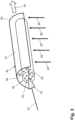
- the mixing device 44 which is located in the first subsystem 11, preferably below a cooling device 32 in the form of an emergency cooler ( Figure 4 ), has a wall 47 which delimits a defined, open mixing space 45.
- the wall 47 of the mixing device 44 only delimits a partial area of the mixing space 45.
- the area of the mixing device 44 not delimited by the wall 47 forms, in accordance with the invention, an inlet area 48 for the discharge volume flow 42 and for the air volume flow 28 into the mixing space 45.
- the mixing device 44 is designed in the form of a half-pipe.
- This half-pipe has a first open front side 49 and an open underside 51.
- the front side 49 and/or the underside 51 serve as the inlet side for the hydrogen discharge volume flow 42 exiting the outflow device 43.
- the open underside 51 of the half-pipe-shaped mixing device 44 also provides an inlet surface via which the air volume flow 28, in particular the exhaust air volume flow, enters the mixing chamber 45.
- the air volume flow 28 can enter the mixing chamber 45 via the entire open underside 51.
- the design of the mixing device 44 creates a hypothetical volume 46 which defines the flushing zone.
- the discharge volume flow 42 enters the mixing chamber 45 via the outflow device 43 in the inlet region 48, is distributed there and mixes with the air volume flow 28.
- a further component in the form of a distribution device 52 is preferably provided, which Figure 3
- the distributor device 52 is preferably designed as a tube made of porous material. In Figure 3 some pores 53 are indicated schematically for clarification.
- the tubular distribution device 52 which consists of porous material, extends over the entire length or almost the entire length of the mixing chamber 45.
- the distribution device 52 preferably interacts with the outflow device 43 in such a way that the discharge volume flow 42 leaving the outflow device 43 enters the distribution device 52 directly or as directly as possible.
- the discharge volume flow 42 penetrates the distribution device 52, thereby influencing its flow properties.
- the discharge volume flow 42 then exits the distribution device 52 at various points via the pores 53 of the distribution device 52 and enters the mixing chamber 45, where it mixes with the air volume flow 28 as evenly as possible and preferably under a preferred reduced pressure.
- the hypothetical volume 46 in this semi-tubular mixing device 44 preferably has the shape of a cylinder that extends around the mixing device 44.
- the exhaust air volume flow 30 resulting from the mixing is diverted in the example shown via a second open end face 50 of the mixing device 44.
- the exhaust air volume flow 30 is passed through the cooler device 32, where the exhaust air volume flow 30 can be further used either for heating purposes or for cooling purposes if necessary or desired.
- the mixing device 44 By using the mixing device 44, the hydrogen discharged from the flushing device 41, in particular from the bellows, is mixed with an increase in the residence time in the defined open mixing space 45 of the mixing device 44. Care must be taken to ensure that there are no ignition sources in the vicinity of the mixing device 44, preferably within the hypothetical volume 46.
- the mixing has the effect that the hydrogen-laden discharge volume flow 42 is diluted by the mixing with the air volume flow 28, which is in particular an exhaust air volume flow that is created or generated elsewhere in the energy system 10, to such an extent that the hydrogen in the discharge volume flow 42 always falls below a critical content limit, which is, for example, less than 2%.
Landscapes
- Chemical & Material Sciences (AREA)
- Engineering & Computer Science (AREA)
- Chemical Kinetics & Catalysis (AREA)
- Electrochemistry (AREA)
- Materials Engineering (AREA)
- Metallurgy (AREA)
- Organic Chemistry (AREA)
- Life Sciences & Earth Sciences (AREA)
- Manufacturing & Machinery (AREA)
- Sustainable Development (AREA)
- Sustainable Energy (AREA)
- General Chemical & Material Sciences (AREA)
- Inorganic Chemistry (AREA)
- Fuel Cell (AREA)
- Electrolytic Production Of Non-Metals, Compounds, Apparatuses Therefor (AREA)
Claims (15)
- Système de rinçage (40) qui est prévu pour rincer au moins un appareil de source d'énergie (15) et/ou au moins un appareil de dissipation d'énergie (16), présentant un appareil de rinçage (41) qui est prévu de sorte qu'il soit capable de générer un flux volumique de purge (42) pendant une opération de rinçage, dans lequel le système de rinçage (40) présente un appareil de mélange (44) disposé en aval de l'appareil de rinçage (41) dans le sens d'écoulement du flux volumique de purge (42), qui est prévu pour mélanger le flux volumique de purge (42) avec un flux volumique d'air (28), caractérisé en ce que l'appareil de mélange (44) présente une chambre de mélange (45) ouverte définie pour le mélange du flux volumique de purge (42) avec le flux volumique d'air (28), en ce que l'appareil de mélange (44) présente à cet effet une paroi (47) délimitant la chambre de mélange (45), en ce que la paroi (47) délimite uniquement une zone partielle de la chambre de mélange (45) de moins de 90 %, et en ce que la zone de l'appareil de mélange (44) non délimitée par la paroi (47) forme une zone d'entrée (48) pour le flux volumique de purge (42) et le flux volumique d'air (28).
- Système de rinçage selon la revendication 1, caractérisé en ce que le système de rinçage (40) présente un appareil d'écoulement (43) qui interagit avec l'appareil de mélange (44) et en ce que l'appareil d'écoulement (43) est conçu en particulier en tant que grille, restricteur, buse ou pompe.
- Système de rinçage selon l'une quelconque des revendications 1 ou 2, caractérisé en ce que l'appareil de mélange (44) présente un appareil de répartition (52) pour répartir le flux volumique de purge (42) dans la chambre de mélange (45), et en ce que l'appareil de répartition (52) est disposé au moins partiellement dans la chambre de mélange (45).
- Système de rinçage selon la revendication 3, caractérisé en ce que l'appareil de répartition (52) est conçu sous forme d'un tube et/ou en ce que l'appareil de répartition (52) est constitué d'un matériau poreux au moins par zones.
- Système de rinçage selon l'une quelconque des revendications 1 à 4, caractérisé en ce que l'appareil de rinçage (41) présente au moins une chambre de stockage, en ce que le flux volumique de purge (42) est ou sera prévu à partir de la chambre de stockage, et en ce que la chambre de stockage est conçue en particulier en tant que soufflet.
- Système de rinçage selon l'une quelconque des revendications 1 à 5, caractérisé en ce que l'appareil de mélange (44) est conçu en forme de capot ou en forme de parapluie ou en forme de coque, ou en ce que l'appareil de mélange (44) présente une paroi s'étendant en forme d'arc.
- Système de rinçage selon l'une quelconque des revendications 1 à 6, caractérisé en ce que l'appareil de mélange (44) est conçu sous forme d'une fraction d'un tube, et en ce que sa paroi (47) délimite la chambre de mélange (45).
- Système de rinçage selon la revendication 7, caractérisé en ce que l'appareil de mélange (44) présente une première face avant ouverte (49) et/ou en ce que l'appareil de mélange (44) présente une face inférieure ouverte (51) et/ou en ce que l'appareil de mélange (44) présente une seconde face avant ouverte (50).
- Système de rinçage selon l'une quelconque des revendications 1 à 8, caractérisé en ce que le contour de l'appareil de mélange (44) prédéfinit une forme pour un volume hypothétique (46) concernant le mélange du flux volumique de purge (42) avec le flux volumique d'air (28).
- Système d'énergie (10) avec un appareil de source d'énergie (15) qui est conçu en tant qu'appareil d'électrolyse, et/ou avec un appareil de dissipation d'énergie (16) qui est conçu en tant qu'appareil de pile à combustible, et avec un système de rinçage (40) pour rincer l'appareil de source d'énergie (15) et/ou l'appareil de dissipation d'énergie (16), caractérisé en ce que le système de rinçage (40) est conçu selon l'une quelconque des revendications 1 à 9.
- Système d'énergie selon la revendication 10, caractérisé en ce que le système d'énergie (10) présente un premier sous-système (11), en ce que l'appareil de source d'énergie (15) et/ou l'appareil de dissipation d'énergie (16) ainsi que le système de rinçage (40) sont des composants du premier sous-système (11), en ce que le premier sous-système (11) présente une zone de mélange (29) qui est prévue de sorte que le flux volumique de purge (42) et le flux volumique d'air (28), en particulier le flux volumique d'air d'évacuation, soient mélangés ou peuvent être mélangés dans celle-ci et en ce que l'appareil de mélange (44) est disposé ou formé dans la zone de mélange (29).
- Système d'énergie selon la revendication 11, caractérisé en ce que le premier sous-système (11) est disposé dans une première armoire de système (12).
- Système d'énergie selon l'une quelconque des revendications 10 à 12, caractérisé en ce qu'il présente au moins un appareil de refroidisseur (32), et en ce que l'appareil de mélange (44) est disposé ou formé sous l'appareil de refroidisseur (32).
- Procédé de fonctionnement d'un système de rinçage (40) selon l'une quelconque des revendications 1 à 9, ou d'un système d'énergie (10) selon l'une quelconque des revendications 10 à 13, caractérisé en ce qu'un flux volumique de purge (42) généré dans le système de rinçage (40) pendant une opération de rinçage est dirigé dans la chambre de mélange (45) ouverte définie et délimitée par la paroi (47) de l'appareil de mélange (44), y est mélangé avec un flux volumique d'air (28), en particulier un flux volumique d'air d'évacuation, et en est évacué en tant que flux volumique d'air rejeté(30).
- Utilisation d'un appareil de mélange (44) qui présente une paroi (47) qui délimite une chambre de mélange ouverte définie (45), dans laquelle la paroi (47) délimite uniquement une zone partielle de la chambre de mélange (45) de moins de 90 % et la zone de l'appareil de mélange (44) non délimitée par la paroi (47) forme une zone d'entrée (48) pour au moins deux flux volumiques pour mélanger un flux volumique de purge (42) généré par un système de rinçage (40) pendant une opération de rinçage d'un appareil de source d'énergie (15) et/ou d'un appareil de dissipation d'énergie (16) d'un système d'énergie (10) avec un flux volumique d'air (28) généré par le système d'énergie (10) à un autre endroit.
Applications Claiming Priority (2)
| Application Number | Priority Date | Filing Date | Title |
|---|---|---|---|
| DE102018133201.7A DE102018133201A1 (de) | 2018-12-20 | 2018-12-20 | Spülsystem und dessen Verwendung in einem Energiesystem |
| PCT/EP2019/086014 WO2020127527A1 (fr) | 2018-12-20 | 2019-12-18 | Système de rinçage et son utilisation dans un système énergétique |
Publications (3)
| Publication Number | Publication Date |
|---|---|
| EP3899094A1 EP3899094A1 (fr) | 2021-10-27 |
| EP3899094B1 true EP3899094B1 (fr) | 2025-01-29 |
| EP3899094C0 EP3899094C0 (fr) | 2025-01-29 |
Family
ID=69105821
Family Applications (1)
| Application Number | Title | Priority Date | Filing Date |
|---|---|---|---|
| EP19832068.1A Active EP3899094B1 (fr) | 2018-12-20 | 2019-12-18 | Système de rinçage et son utilisation dans un système énergétique |
Country Status (5)
| Country | Link |
|---|---|
| US (1) | US12142801B2 (fr) |
| EP (1) | EP3899094B1 (fr) |
| CN (1) | CN113412346B (fr) |
| DE (1) | DE102018133201A1 (fr) |
| WO (1) | WO2020127527A1 (fr) |
Families Citing this family (1)
| Publication number | Priority date | Publication date | Assignee | Title |
|---|---|---|---|---|
| CN117810496B (zh) * | 2024-02-29 | 2024-05-17 | 上海清能合睿兹新能源科技有限公司 | 燃料电池尾排装置、燃料电池系统及燃料电池汽车 |
Citations (1)
| Publication number | Priority date | Publication date | Assignee | Title |
|---|---|---|---|---|
| US20020094469A1 (en) * | 2001-01-18 | 2002-07-18 | Toyota Jidosha Kabushiki Kaisha | Onboard fuel cell system band method of discharging hydrogen-off gas |
Family Cites Families (15)
| Publication number | Priority date | Publication date | Assignee | Title |
|---|---|---|---|---|
| JP2003282122A (ja) | 2002-02-19 | 2003-10-03 | Proton Energy Systems Inc | エネルギ蓄積および回収システムならびにその使用方法 |
| JP4649861B2 (ja) * | 2003-09-09 | 2011-03-16 | トヨタ自動車株式会社 | 燃料電池システム |
| JP4557738B2 (ja) * | 2005-02-04 | 2010-10-06 | トヨタ自動車株式会社 | 燃料電池車の冷却装置 |
| JP4984543B2 (ja) * | 2005-07-21 | 2012-07-25 | 日産自動車株式会社 | 燃料電池システム |
| US20080160360A1 (en) * | 2006-04-13 | 2008-07-03 | Fennimore Keith A | Fuel cell purge cycle apparatus and method |
| WO2012053324A1 (fr) * | 2010-10-21 | 2012-04-26 | 日産自動車株式会社 | Procédé de fonctionnement d'un système de batterie à combustible |
| JP5595231B2 (ja) * | 2010-11-05 | 2014-09-24 | 本田技研工業株式会社 | 燃料電池システム |
| CN104160538B (zh) * | 2012-03-08 | 2016-10-12 | 丰田自动车株式会社 | 燃料电池系统及其控制方法 |
| DE102014206754A1 (de) * | 2014-04-08 | 2015-10-08 | Bayerische Motoren Werke Aktiengesellschaft | Vorrichtung zum Austragen eines Purge-Massenstroms |
| EP3214684B1 (fr) * | 2014-10-28 | 2022-05-04 | Nissan Motor Co., Ltd. | Système de pile à combustible et procédé de commande correspondant |
| CN107925102B (zh) | 2015-08-31 | 2021-05-25 | 京瓷株式会社 | 燃料电池模块以及燃料电池装置 |
| DK3380652T3 (da) * | 2015-11-25 | 2021-11-22 | Hps Home Power Solutions Gmbh | Dynamisk purgekammer |
| ES2890329T3 (es) | 2015-11-25 | 2022-01-18 | Hps Home Power Solutions Gmbh | Instalación doméstica de energía y método de operación para operar una instalación doméstica de energía |
| ES3002182T3 (en) | 2015-11-25 | 2025-03-06 | Hps Home Power Solutions Ag | Domestic power plant and method for operating a domestic power plant |
| DE102016224652A1 (de) * | 2016-12-12 | 2018-06-14 | Robert Bosch Gmbh | Mischvorrichtung und eine Brennstoffzelle mit einer derartigen Mischvorrichtung |
-
2018
- 2018-12-20 DE DE102018133201.7A patent/DE102018133201A1/de not_active Ceased
-
2019
- 2019-12-18 EP EP19832068.1A patent/EP3899094B1/fr active Active
- 2019-12-18 WO PCT/EP2019/086014 patent/WO2020127527A1/fr not_active Ceased
- 2019-12-18 US US17/416,002 patent/US12142801B2/en active Active
- 2019-12-18 CN CN201980091662.5A patent/CN113412346B/zh active Active
Patent Citations (1)
| Publication number | Priority date | Publication date | Assignee | Title |
|---|---|---|---|---|
| US20020094469A1 (en) * | 2001-01-18 | 2002-07-18 | Toyota Jidosha Kabushiki Kaisha | Onboard fuel cell system band method of discharging hydrogen-off gas |
Also Published As
| Publication number | Publication date |
|---|---|
| CN113412346B (zh) | 2024-03-15 |
| CN113412346A (zh) | 2021-09-17 |
| US20220115681A1 (en) | 2022-04-14 |
| US12142801B2 (en) | 2024-11-12 |
| EP3899094A1 (fr) | 2021-10-27 |
| WO2020127527A1 (fr) | 2020-06-25 |
| DE102018133201A1 (de) | 2020-06-25 |
| EP3899094C0 (fr) | 2025-01-29 |
Similar Documents
| Publication | Publication Date | Title |
|---|---|---|
| EP3899095B1 (fr) | Système d'énergie avec un système de rinçage, et procédé permettant de surveiller ledit système | |
| EP2346982B1 (fr) | Dispositif et procédé de régulation d'apport de gaz ou de transport de gaz dans un système de stockage de gaz | |
| DK2531726T4 (da) | Fordelingsanlæg, især fordelingsanlæg til et offshore-vindenergianlæg | |
| EP3899096B1 (fr) | Système d'énergie et procédé de surveillance de pression de conduite | |
| WO2015180746A1 (fr) | Système de piles à combustible | |
| DE102012007377A1 (de) | Brennstoffzellensystem mit wenigstens einer Brennstoffzelle | |
| DE102013014413A1 (de) | Verfahren zur Druckregelung | |
| EP3899094B1 (fr) | Système de rinçage et son utilisation dans un système énergétique | |
| DE102012219061A1 (de) | Brennstoffzellensystem mit stabilisiertem H2-Mitteldruck | |
| DE102022109043A1 (de) | Vorrichtung zur Aufbereitung einer Elektrolytflüssigkeit | |
| WO2020127515A1 (fr) | Système énergétique et procédé d'ajustement de pression dans un système énergétique | |
| DE202019102516U1 (de) | Energiesystem | |
| EP4497843A2 (fr) | Prévention d'une atmosphère explosible dans un système d'énergie | |
| EP2602454A1 (fr) | Réservoir de gaz sous pression commercial | |
| DE102013019825B4 (de) | Ventileinrichtung für einen Druckgasspeicher | |
| EP4570964A1 (fr) | Dispositif de rinçage destiné au stockage intermédiaire d'un milieu gazeux provenant d'un processus de rinçage | |
| EP4483465A1 (fr) | Dispositif de stabilisation de réseaux électriques comprenant des cavernes pour le stockage du gaz | |
| EP4317761A1 (fr) | Dispositif de stockage de gaz | |
| DE102014017985A1 (de) | Gas/Gas-Befeuchter und Gehäuse dafür | |
| EP3166196B1 (fr) | Centrale électrique, ensemble de centrale électrique comprenant une centrale électrique et procédé de fonctionnement | |
| DE102022131861A1 (de) | Kondensatablaufeinrichtung und Verfahren zu deren Betrieb | |
| DE102013003740A1 (de) | Wasserstoffversorgungssystem | |
| DE102011015827A1 (de) | Druckluftkonditionierungssystem | |
| DE102022114038A1 (de) | Energiesystem | |
| DE102013003426A1 (de) | Vorrichtung zum Testen eines Brennstoffzellensystems |
Legal Events
| Date | Code | Title | Description |
|---|---|---|---|
| STAA | Information on the status of an ep patent application or granted ep patent |
Free format text: STATUS: UNKNOWN |
|
| STAA | Information on the status of an ep patent application or granted ep patent |
Free format text: STATUS: THE INTERNATIONAL PUBLICATION HAS BEEN MADE |
|
| PUAI | Public reference made under article 153(3) epc to a published international application that has entered the european phase |
Free format text: ORIGINAL CODE: 0009012 |
|
| STAA | Information on the status of an ep patent application or granted ep patent |
Free format text: STATUS: REQUEST FOR EXAMINATION WAS MADE |
|
| 17P | Request for examination filed |
Effective date: 20210630 |
|
| AK | Designated contracting states |
Kind code of ref document: A1 Designated state(s): AL AT BE BG CH CY CZ DE DK EE ES FI FR GB GR HR HU IE IS IT LI LT LU LV MC MK MT NL NO PL PT RO RS SE SI SK SM TR |
|
| DAV | Request for validation of the european patent (deleted) | ||
| DAX | Request for extension of the european patent (deleted) | ||
| RAP1 | Party data changed (applicant data changed or rights of an application transferred) |
Owner name: HPS HOME POWER SOLUTIONS AG |
|
| STAA | Information on the status of an ep patent application or granted ep patent |
Free format text: STATUS: EXAMINATION IS IN PROGRESS |
|
| 17Q | First examination report despatched |
Effective date: 20230817 |
|
| GRAP | Despatch of communication of intention to grant a patent |
Free format text: ORIGINAL CODE: EPIDOSNIGR1 |
|
| STAA | Information on the status of an ep patent application or granted ep patent |
Free format text: STATUS: GRANT OF PATENT IS INTENDED |
|
| INTG | Intention to grant announced |
Effective date: 20240731 |
|
| GRAS | Grant fee paid |
Free format text: ORIGINAL CODE: EPIDOSNIGR3 |
|
| GRAA | (expected) grant |
Free format text: ORIGINAL CODE: 0009210 |
|
| STAA | Information on the status of an ep patent application or granted ep patent |
Free format text: STATUS: THE PATENT HAS BEEN GRANTED |
|
| AK | Designated contracting states |
Kind code of ref document: B1 Designated state(s): AL AT BE BG CH CY CZ DE DK EE ES FI FR GB GR HR HU IE IS IT LI LT LU LV MC MK MT NL NO PL PT RO RS SE SI SK SM TR |
|
| REG | Reference to a national code |
Ref country code: GB Ref legal event code: FG4D Free format text: NOT ENGLISH |
|
| REG | Reference to a national code |
Ref country code: CH Ref legal event code: EP |
|
| REG | Reference to a national code |
Ref country code: DE Ref legal event code: R096 Ref document number: 502019012894 Country of ref document: DE |
|
| REG | Reference to a national code |
Ref country code: IE Ref legal event code: FG4D Free format text: LANGUAGE OF EP DOCUMENT: GERMAN |
|
| U01 | Request for unitary effect filed |
Effective date: 20250212 |
|
| U07 | Unitary effect registered |
Designated state(s): AT BE BG DE DK EE FI FR IT LT LU LV MT NL PT RO SE SI Effective date: 20250218 |
|
| PG25 | Lapsed in a contracting state [announced via postgrant information from national office to epo] |
Ref country code: RS Free format text: LAPSE BECAUSE OF FAILURE TO SUBMIT A TRANSLATION OF THE DESCRIPTION OR TO PAY THE FEE WITHIN THE PRESCRIBED TIME-LIMIT Effective date: 20250429 |
|
| PG25 | Lapsed in a contracting state [announced via postgrant information from national office to epo] |
Ref country code: PL Free format text: LAPSE BECAUSE OF FAILURE TO SUBMIT A TRANSLATION OF THE DESCRIPTION OR TO PAY THE FEE WITHIN THE PRESCRIBED TIME-LIMIT Effective date: 20250129 |
|
| PG25 | Lapsed in a contracting state [announced via postgrant information from national office to epo] |
Ref country code: ES Free format text: LAPSE BECAUSE OF FAILURE TO SUBMIT A TRANSLATION OF THE DESCRIPTION OR TO PAY THE FEE WITHIN THE PRESCRIBED TIME-LIMIT Effective date: 20250129 |
|
| PG25 | Lapsed in a contracting state [announced via postgrant information from national office to epo] |
Ref country code: IS Free format text: LAPSE BECAUSE OF FAILURE TO SUBMIT A TRANSLATION OF THE DESCRIPTION OR TO PAY THE FEE WITHIN THE PRESCRIBED TIME-LIMIT Effective date: 20250529 Ref country code: NO Free format text: LAPSE BECAUSE OF FAILURE TO SUBMIT A TRANSLATION OF THE DESCRIPTION OR TO PAY THE FEE WITHIN THE PRESCRIBED TIME-LIMIT Effective date: 20250429 |
|
| PG25 | Lapsed in a contracting state [announced via postgrant information from national office to epo] |
Ref country code: HR Free format text: LAPSE BECAUSE OF FAILURE TO SUBMIT A TRANSLATION OF THE DESCRIPTION OR TO PAY THE FEE WITHIN THE PRESCRIBED TIME-LIMIT Effective date: 20250129 |
|
| PG25 | Lapsed in a contracting state [announced via postgrant information from national office to epo] |
Ref country code: GR Free format text: LAPSE BECAUSE OF FAILURE TO SUBMIT A TRANSLATION OF THE DESCRIPTION OR TO PAY THE FEE WITHIN THE PRESCRIBED TIME-LIMIT Effective date: 20250430 |
|
| PG25 | Lapsed in a contracting state [announced via postgrant information from national office to epo] |
Ref country code: SM Free format text: LAPSE BECAUSE OF FAILURE TO SUBMIT A TRANSLATION OF THE DESCRIPTION OR TO PAY THE FEE WITHIN THE PRESCRIBED TIME-LIMIT Effective date: 20250129 |
|
| PG25 | Lapsed in a contracting state [announced via postgrant information from national office to epo] |
Ref country code: CZ Free format text: LAPSE BECAUSE OF FAILURE TO SUBMIT A TRANSLATION OF THE DESCRIPTION OR TO PAY THE FEE WITHIN THE PRESCRIBED TIME-LIMIT Effective date: 20250129 |
|
| PG25 | Lapsed in a contracting state [announced via postgrant information from national office to epo] |
Ref country code: SK Free format text: LAPSE BECAUSE OF FAILURE TO SUBMIT A TRANSLATION OF THE DESCRIPTION OR TO PAY THE FEE WITHIN THE PRESCRIBED TIME-LIMIT Effective date: 20250129 |
|
| PLBE | No opposition filed within time limit |
Free format text: ORIGINAL CODE: 0009261 |
|
| STAA | Information on the status of an ep patent application or granted ep patent |
Free format text: STATUS: NO OPPOSITION FILED WITHIN TIME LIMIT |
|
| 26N | No opposition filed |
Effective date: 20251030 |