EP4497843A2 - Prévention d'une atmosphère explosible dans un système d'énergie - Google Patents
Prévention d'une atmosphère explosible dans un système d'énergie Download PDFInfo
- Publication number
- EP4497843A2 EP4497843A2 EP24189413.8A EP24189413A EP4497843A2 EP 4497843 A2 EP4497843 A2 EP 4497843A2 EP 24189413 A EP24189413 A EP 24189413A EP 4497843 A2 EP4497843 A2 EP 4497843A2
- Authority
- EP
- European Patent Office
- Prior art keywords
- hydrogen
- energy
- internal
- external
- internal system
- Prior art date
- Legal status (The legal status is an assumption and is not a legal conclusion. Google has not performed a legal analysis and makes no representation as to the accuracy of the status listed.)
- Withdrawn
Links
Images


Classifications
-
- C—CHEMISTRY; METALLURGY
- C25—ELECTROLYTIC OR ELECTROPHORETIC PROCESSES; APPARATUS THEREFOR
- C25B—ELECTROLYTIC OR ELECTROPHORETIC PROCESSES FOR THE PRODUCTION OF COMPOUNDS OR NON-METALS; APPARATUS THEREFOR
- C25B1/00—Electrolytic production of inorganic compounds or non-metals
- C25B1/01—Products
- C25B1/02—Hydrogen or oxygen
-
- C—CHEMISTRY; METALLURGY
- C25—ELECTROLYTIC OR ELECTROPHORETIC PROCESSES; APPARATUS THEREFOR
- C25B—ELECTROLYTIC OR ELECTROPHORETIC PROCESSES FOR THE PRODUCTION OF COMPOUNDS OR NON-METALS; APPARATUS THEREFOR
- C25B15/00—Operating or servicing cells
- C25B15/02—Process control or regulation
-
- H—ELECTRICITY
- H01—ELECTRIC ELEMENTS
- H01M—PROCESSES OR MEANS, e.g. BATTERIES, FOR THE DIRECT CONVERSION OF CHEMICAL ENERGY INTO ELECTRICAL ENERGY
- H01M8/00—Fuel cells; Manufacture thereof
- H01M8/04—Auxiliary arrangements, e.g. for control of pressure or for circulation of fluids
- H01M8/04082—Arrangements for control of reactant parameters, e.g. pressure or concentration
- H01M8/04089—Arrangements for control of reactant parameters, e.g. pressure or concentration of gaseous reactants
Definitions
- the present invention relates firstly to methods for preventing an explosive atmosphere in an energy system which can occur during an incident in the energy system. Furthermore, the invention also relates to such an energy system.
- Energy systems of this type are already known in many different ways in the state of the art. Such systems are used, for example, to generate and provide energy for a wide range of applications.
- One known type of such energy system is a building energy system by means of which energy is generated and provided for the building in various forms.
- hydrogen is generated in an electrolysis device in a first operating mode of the energy system.
- the electrical current required for the electrolysis device can be generated and provided, for example, by means of photovoltaics, wind power or using other renewable energy sources.
- the energy system can also have a battery device for short-term storage of electrical energy.
- the hydrogen generated is then stored in a storage device until it is used.
- the hydrogen is removed from the storage device and used in a fuel cell device.
- the components of the energy system described above are usually spatially separated from one another and connected to one another via a connecting line device.
- the hydrogen generated during electrolysis is usually still moist. Therefore, it must be dried beforehand before it can be stored in the storage device. Suitable drying devices are used for this purpose.
- the hydrogen system of the energy system which is a sub-area of the energy system that involves the production, treatment, storage and Use of hydrogen is involved, and in which hydrogen is consequently present during operation, for example in the electrolysis device, in the drying device and in the connecting line device, there is a limited amount of hydrogen during normal operation and for a limited period of time after leaving normal operation.
- the electrolysis device in particular an electrolysis stack of the electrolysis device, loses hydrogen during operation and when not in use, for example via the cathode.
- This hydrogen is usually sufficiently diluted by permanent technical ventilation of the energy system.
- a failure of the battery/power electronics of the energy system leads to a failure of the ventilation.
- an explosive atmosphere can develop in the energy system.
- an emergency power supply is usually used which maintains the ventilation volume flow and thus the safe dilution of escaping hydrogen to well below the ignition limit of hydrogen-air mixtures.
- the applicant discloses a safety concept to prevent dangerous explosive atmospheres from occurring.
- This known solution involves the operation of a purging system, which is part of an internal system of the energy system.
- the purging system has the particular task of converting the hydrogen-containing discharge volume flows, which occur in pulses with relatively high volume flow peaks, particularly in normal operation, into volume flows that are uniformly distributed over time with significantly smaller volume flow peaks and of diluting them sufficiently with an air flow in a specially provided mixing zone within the internal system.
- This diluted discharge volume flow is then released from the internal system to the environment via an outlet device.
- a basic example of an emergency power supply is in the WO 2015/144446 A1
- This emergency power supply serves as a backup power supply for an electrolysis plant after the actual regular power supply fails.
- the electrolysis plant is supplied with power from the energy potential present in the electrolysis stack and convertible into electrical current.
- this Emergency power supply may not be used as an emergency power supply for the ventilation described above.
- Energy systems of the type mentioned above are in particular self-sufficient systems that generate electricity independently of an existing power grid. Electrical consumers, such as ventilation, but also emergency generators and the like, are supplied with the electricity generated by the energy system. There is therefore a need to design the energy-consuming components of the energy system to be as energy-efficient and as small as possible.
- an explosive atmosphere can arise in the energy system if a leakage exceeding a defined limit occurs in a component related to hydrogen in the energy system.
- the present invention is based on the object of providing a method for avoiding an explosive atmosphere in an energy system when an incident occurs, as well as a correspondingly developed energy system in which the prevention of the formation of an explosive atmosphere is realized in a simple and energy-saving manner, in particular by using already existing components of the energy system.
- a method for preventing the formation of an explosive atmosphere in an energy system, the method being carried out when a corresponding incident occurs in the energy system.
- An incident is generally a disruption of the intended operation of the energy system, with the incident in the present case relating to the hydrogen sector.
- the invention is not limited to specific types of incidents. Some examples of possible incidents are described in more detail below.
- the present invention is intended to prevent an unwanted, explosive atmosphere from being created due to the hydrogen during operation of the energy system in the event of a malfunction.
- the energy system which is described in more detail below in connection with the third aspect of the invention, has a number of basic features.
- the energy system is in particular a building energy system that generates and provides various forms of energy for the building.
- the energy system has a first subsystem, in particular designed as an internal system.
- Internal system in this case means that this system is located inside the building.
- the internal system has a number of different components.
- the internal system has a first hydrogen system.
- a hydrogen system is in particular a system, i.e. a whole consisting of several components that has to do with hydrogen.
- the first hydrogen system therefore preferably represents a subsystem of the energy system, and in particular a subsystem of the internal system.
- the individual components of the first hydrogen system are used to produce hydrogen, for example by means of electrolysis, to store hydrogen, for example in the form of a storage device, to treat hydrogen, for example for drying, filtering and the like, to transport hydrogen, for example in the form of a connecting line device, to influence the volume flow, for example in the form of valve devices, and to consume hydrogen, for example in the form of a fuel cell device.
- the first hydrogen system has in particular at least one hydrogen source.
- a hydrogen source is in particular a component from which hydrogen emerges.
- the first hydrogen system comprises an electrolysis device which is provided for generating hydrogen and optionally a fuel cell device, whereby the invention is not limited thereto.
- the energy system has a second subsystem, in particular designed as an external system.
- this also has various components, in particular a second hydrogen system.
- the second hydrogen system has a storage device for storing the hydrogen generated by the electrolysis device.
- the storage device is, for example, part of the second hydrogen system, and thus of the second subsystem.
- the second hydrogen system has an interface to a storage device for storing the hydrogen generated by the electrolysis device.
- the storage device is not part of the second hydrogen system. Combinations of both alternatives are also possible.
- the storage device in turn, can consist of various components.
- the storage device can have a high-pressure storage device consisting of one or more high-pressure storage containers, whereby two or more high-pressure storage containers can be combined to form a storage bundle.
- the storage device can also have a medium-pressure storage device consisting of one or more medium-pressure storage containers, which serves to temporarily store the hydrogen generated before it is stored in the high-pressure storage device for final storage.
- Such storage devices are described in greater detail below in connection with the energy system according to the invention.
- the second hydrogen system has in particular at least one Hydrogen source.
- a hydrogen source is in particular a component from which hydrogen escapes.
- the second subsystem has a defined delivery point for hydrogen. Via this delivery point, the hydrogen can be released from the second subsystem in a regulated and controlled manner.
- the delivery point is preferably a special area, such as a so-called Ex zone, in particular an Ex zone 2. Or the delivery point is located in such an area.
- Ex zones are generally specially marked areas in which there is a risk of explosion because ignitable concentrations of flammable gases, in this case hydrogen, can occur in them.
- An Ex zone 2 is in particular an area in which an explosive atmosphere consisting of a mixture of air with flammable substances in the form of gas, vapor or mist is not expected to occur during normal operation, and if it does occur, then only rarely and only for a short time.
- the energy system further comprises a connecting line device comprising at least one line section, preferably several line sections, which are provided for transporting hydrogen. At least one first line section is provided in the internal system and thus forms a component of the first hydrogen system. At least one second line section is provided in the external system and thus forms a component of the second hydrogen system. The at least one first line section of the internal system is connected to the at least one second line section of the external system via a line bus, i.e. via a transmission path or connection path.
- the energy system has both a first subsystem, an internal system, with a first hydrogen system consisting of an electrolysis device and optionally a fuel cell device, and a second subsystem, an external system, where the hydrogen produced is stored.
- the external system also has a hydrogen release point, through which the hydrogen is released into the environment in a controlled manner when required.
- the components of the internal system and the external system are connected via the connecting line device, with the direct connection between the internal system and the external system being made via a line bus.
- explosion protection is implemented in the energy system.
- explosion protection is implemented by a safe, pressure-free state in the internal system of the energy system. This provides redundant safety in the event of leaks in a hydrogen-based energy system.
- explosion protection is implemented by a leak test and pressure relief in the external system. This provides a leak test and pressure relief of a hydrogen system.
- explosion protection is implemented by a combination of the first and second aspects of the invention. The methods according to the invention are carried out when an incident related to hydrogen occurs in the energy system, as a result of which an unwanted, explosive atmosphere arises.
- the method is characterized in that when a malfunction occurs or when a malfunction is detected, the first hydrogen system in the internal system is brought into a pressure-free state, in particular in an automated, safety-oriented manner, by transporting hydrogen located in the first hydrogen system of the internal system from the internal system via the line bus into the external system and there to the delivery point.
- the electrolysis device in the drying and in the connecting line device and here in particular in the line bus, which represents the connecting line between the internal system and the external system, for example, there is always hydrogen in regular operation.
- the electrolysis stack of the electrolysis device loses hydrogen during operation and when not in use, for example via the cathode. This hydrogen is usually diluted by the permanent technical ventilation of the energy system.
- an explosive atmosphere can develop in the internal system.
- an emergency power supply is required that maintains the ventilation volume flow.
- the pressure in the electrolysis device is actively reduced according to the method of the first aspect of the invention.
- a special valve device is provided in the external system.
- the line bus between the internal system and the external system allows the hydrogen to be safely discharged via a designated discharge point in the external system. After the hydrogen has been removed, there is no further need for ventilation in the internal system for safety reasons in connection with hydrogen.
- the emergency power supply can then be deactivated or operated for longer with significantly reduced energy requirements, for example to continue recording system data.
- the emergency power supply is designed in such a way that the ventilation of the internal system and the energy requirements of the control technology, such as controllers, valve devices and etc., are available for this period. In the event of a failure of the depressurized hydrogen system, the capacity required for the emergency power supply is thus significantly smaller.
- an emergency power supply device assigned to the energy system is automatically activated in the event of a failure of the ventilation device, which supplies required components in relation to hydrogen of the internal system and/or the external system, in particular valves and/or controllers, with electrical energy, so that the hydrogen located in the first hydrogen system of the internal system is transported from the internal system via the line bus into the external system and from there to the delivery point.
- a control device is assigned to the energy system.
- a leakage exceeding a defined limit is detected in the energy system as a malfunction
- required components relating to hydrogen of the internal system and/or the external system in particular valves and/or controllers, are activated so that the hydrogen in the first hydrogen system of the internal system can pass from the internal system via the line bus into the external system and there to the delivery point.
- a control device is assigned to the energy system. If the control device detects a leakage that exceeds a defined limit value, or if the control device receives information regarding a leakage that exceeds a defined limit value, the control device activates the required components of the internal system and/or of the external system, so that the hydrogen located in the first hydrogen system of the internal system is transported from the internal system via the line bus into the external system and to the delivery point, wherein the control device in particular deactivates the components after the hydrogen has been discharged via the delivery point.
- a central valve device which is arranged in particular on the input side of the line bus in the first line section in the internal system and/or on the output side of the line bus in the second line section in the external system, is activated so that the hydrogen located in the first hydrogen system of the internal system is transported from the internal system via the line bus into the external system and there to the delivery point.
- the first hydrogen system is brought into a pressure-free state, i.e. a safe pressure-free state is created in the internal system.
- a pressure-free state i.e. a safe pressure-free state is created in the internal system.
- the first hydrogen system is relaxed and/or emptied.
- This is done in such a way that hydrogen in the first hydrogen system of the internal system is transported from the internal system to the external system via the line bus and is transported in the external system to the delivery point.
- the starting situation is, for example, as follows: For example, when the electrolysis device is switched off, it releases steadily decreasing, smaller amounts of hydrogen into the environment over time until the stack pressure has equalized with the ambient pressure. In the case of technically sealed components/connections, it can be assumed that the tightness is not guaranteed permanently.
- the ventilation volume flow provided for this reason continuously ensures the required dilution of hydrogen with air.
- a ventilation failure can lead to the formation of an explosive atmosphere in the internal system due to even small amounts of leakage. This situation can be avoided, for example, by secure ventilation using an emergency power device.
- the external system has a discharge point, which is designed, for example, as a defined Ex zone 2 or is located in such a zone.
- the internal system and the external system are connected by a line bus.
- the amount of hydrogen in the internal system can be safely discharged at any time, especially in the event of a hazard, through the discharge point, for example through the defined Ex zone 2 in the area of the external system.
- the principle does not require an additional line to the outside.
- the fail-safe power supply or the emergency power supply of the fans in the interior system can be significantly limited in time with the solution according to the invention.
- the tightness requirements for the components of the interior system with regard to hydrogen can be reduced because the state "system is under pressure + no ventilation available" no longer has to be taken into account from a safety perspective.
- Safety requirements for the ventilation sensors and actuators can also be reduced.
- a risk from spontaneous and high leaks can be reduced in direct reaction by reducing the pressure.
- the method according to the invention takes a different approach than the WO 2020/127537A1
- the method according to the invention works differently, since the hydrogen is not released via the internal system, but is first transported to the external system and then to a release point.
- a flushing process is carried out. If the discharge volume flow from the flushing process has too much hydrogen, it is diluted.
- a fault is first detected.
- the individual components of the first hydrogen system of the internal system are brought into a pressure-free state.
- the hydrogen in the components is the pipe system to a delivery point which, according to the invention, is located in the external system.
- the known solution monitors the functional and safe operation of a purging system.
- the hydrogen is released into the internal system in a controlled manner and diluted.
- purging is stopped and ventilation is increased if necessary.
- the purging system is switched off, the individual components of the first hydrogen system remain under pressure in the known solution and lose the pressure and hydrogen only very slowly, for example via seals, the electrolysis device or normal, intended leakage points. Conscious, active depressurization is not provided for here.
- the present invention takes a different approach by releasing pressure via the external system. If malfunctions occur in the first hydrogen system in the internal system, the hydrogen content in the hydrogen components can be quickly reduced and, in particular, actively released to ambient pressure. A long and initially increased run-on of a ventilation device for dilution can thus be avoided, or at least reduced, which in particular also leads to energy savings.
- the method according to the first aspect of the invention enables the synergistic use of the entire energy system, i.e. the use of existing actuators and system-characterizing pipelines, for example the line bus, for the safe removal of hydrogen.
- a specific design/reduction of the emergency power functionality for the dilution concept due to the fan supply through additional reactive measures is provided.
- the use of technically tight connections/components in the leakage-monitored area is possible. Detection and reaction are provided at all times.
- a method for preventing the formation of an explosive atmosphere in an energy system when an incident occurs is provided, which method has the features of independent claim 8.
- the energy system has the basic features described above, so that at this point reference is made in full to the relevant statements, as well as to the general description of the invention, above.
- the method is characterized in that the energy system is operated in a discontinuous mode of operation in which, due to changing processes, individual components relating to hydrogen in the first hydrogen system in the internal system and/or in the second hydrogen system in the external system are temporarily not used and that, in particular automatically, a leak test is carried out in those components that are not used.
- the method of the second aspect is also designed according to the first aspect of the invention.
- Such a method thus represents a combination of the first and second aspects of the invention.
- reference is therefore also made in full to the statements on the first aspect of the invention, as well as to the general description of the invention.
- the energy system according to the second aspect is operated in a discontinuous mode of operation. This is an operation with interruptions. Due to changing processes, as will be explained in more detail below, individual components in relation to hydrogen in the first hydrogen system in the internal system and/or in the second hydrogen system in the external system are temporarily not used.
- the method according to the invention now provides that a leak test is carried out, in particular automatically, in those components that are not being used. This can in turn be carried out via a control device of the energy system. If the control device detects information or receives information that a component is currently not being used, the control device can initiate a leak test. Explanatory examples of this can be found further down in the description.
- the leak test detects that there is a leak that exceeds a defined limit value
- the first hydrogen system in the internal system, in particular at least one hydrogen source thereof, and/or the second hydrogen system in the external system, in particular at least one hydrogen source thereof is blocked. This is preferably done via the control device.
- a central valve device which is arranged in particular on the inlet side of the line bus in the first line section in the internal system and/or on the outlet side of the line bus in the second line section in the external system, is activated, preferably via the control device, so that the hydrogen in the first hydrogen system of the internal system is transported from the internal system via the line bus into the external system and there to the delivery point and/or so that the hydrogen in the second hydrogen system of the external system is transported from the external system via the second line section to the delivery point.
- explosion protection is created by leak testing and pressure relief in the external system.
- the starting point is, for example, as follows:
- the external system is directly connected to the volumetrically large hydrogen storage facilities, such as high-pressure storage facilities and/or medium-pressure storage facilities, or the hydrogen storage facilities are components of the external system.
- the external system does not have a designated Ex zone in the area of the fluid technology components, for example, but preferably has a hydrogen delivery point that represents such a zone or is located in such a zone.
- the basis for this is, for example, ensuring that the connections/components are technically tight in the long term. Components that are only technically tight by definition must, however, be regularly checked for Leakage can be tested.
- leakage can only be proven by manual testing on site. Due to the considerable volume of the storage devices that are directly connected to the fluid system, in particular to the connecting line device, a metrological leak test is not possible or only possible to a limited extent, since the amount of leakage is defined by the pressure difference, the time and the geometric volume. If the geometric volume is too large, the statement/test is inaccurate or very slow. If leaks are detected by a metrological leak test, no direct control measures can be derived. In particular, organizational measures are derived. An urgent service call is expensive and slow. For the reasons mentioned above, all connections and components are designed to be technically tight in the long term. This is a major cost driver.
- shut-off devices such as valve devices, such as solenoid valves
- the second connecting line section in the external system and all components therein related to hydrogen that are downstream of these shut-off devices, i.e. in the direction of the storage devices, in front of the shut-off devices, are volumetrically small and are accordingly separated from the storage devices.
- a regular leak test can be carried out. Leaks can thus be determined precisely and quantitatively in the monitored area. The dangerous quantity is greatly reduced due to the shut-off devices. If a leakage limit is exceeded, a valve device, such as a solenoid valve, can be activated in a central position - see also the explanations on depressurizing the internal system above - to safely depressurize the hydrogen system. A risk from the formation of an explosive atmosphere can be avoided, preferably preventively.
- the external system preferably has a defined Ex zone 2 in the area of the discharge point.
- the amount of hydrogen in the monitored area can be safely discharged at any time, especially in the event of a hazard.
- the method according to the second aspect of the invention has a number of advantages. This results in reduced technical tightness requirements for all components in the monitored area. Leakage monitoring and reactive measures ensure primary explosion protection. Automation results in a reduced dependence on organizational measures and a reduced manual testing effort. A risk from spontaneous and high leaks can be reduced in direct reaction by reducing pressure.
- the discontinuous operation of the system enables quasi-continuous leak testing. Leak testing and pressure relief represent primary explosion protection in the complex storage system.
- Hydrogen production and consumption are largely discontinuous processes. Accordingly, downtimes between processes or changing processes can be used to check the tightness of the hydrogen-carrying pipes, fittings and components.
- a leak test can be carried out in the areas that are not required for the respective processes. For example, the pressure drop over time is determined. If leaks or critical leaks are detected in the different areas, operation can be stopped immediately. blocked in order to minimize the critical amounts of hydrogen. In addition, the amount of hydrogen in the specific section can be specifically discharged via a discharge point.
- the method according to the first aspect of the invention and/or the method according to the second aspect of the invention checks whether there is a leakage above a defined limit value and/or a leak test in the component(s) with respect to hydrogen by determining the pressure drop over time.
- the components in the first hydrogen system of the internal system and in the second hydrogen system of the external system for example the corresponding connecting line sections, but also the line bus as a connection between the corresponding line sections, are filled with hydrogen at an increased pressure. If there is a leak, the pressure will drop over time. The leak rate can then be calculated from the pressure difference, multiplied by the volume and divided by the measurement time, which is preferably done in the control device.
- an energy system in particular a building energy system, which has the features of independent patent claim 12.
- the energy system firstly has the basic features described above, so that at this point reference is also made in full to the relevant statements, as well as to the general description of the invention, above.
- the energy system is characterized in that, in order to avoid the formation of an explosive atmosphere in the energy system when an incident occurs, the energy system is designed to carry out a method according to the first aspect of the invention and/or according to the second aspect of the invention, or that a method according to the first aspect of the invention and/or according to the second aspect of the invention is carried out.
- the energy system in order to avoid repetition, reference is therefore also made in full to the corresponding statements on the first and second aspects of the invention.
- the energy system has a control device which is designed to carry out the inventive methods according to the first and second aspects of the invention.
- a control device which is designed to carry out the inventive methods according to the first and second aspects of the invention.
- At least one valve device is assigned to the storage device in the second line section of the external system.
- the valve devices which are preferably automatic shut-off devices, for example solenoid valves, are positioned as close as possible to the storage device, for example the high-pressure storage device and/or the medium-pressure storage device, in terms of fluid technology.
- the second line section and the components relating to hydrogen in the external system are designed to be small in terms of flow before the valve device.
- the second line section in the external system and all components relating to hydrogen are small in volume downstream of this valve device and are accordingly separated from the storage device.
- the energy system can also include other components.
- the energy system can have a ventilation device and/or be connected to a heat pump device.
- the heat pump device is preferably designed as an air/air heat pump, in particular an exhaust air/air heat pump, or as an air/water heat pump or as an exhaust air/water heat pump. Heat pumps per se are known in the prior art and are familiar to those skilled in the art.
- the energy system is in particular a whole consisting of several components, whereby the components are connected to one another to form a dedicated unit.
- the energy system is a system for generating or providing energy, preferably electrical energy.
- the invention is not limited to specific types of energy systems.
- the energy system is a building energy system.
- Building energy systems are basically known from the prior art and serve to supply buildings, for example low-energy houses, passive houses or zero-energy houses, with energy in the form of heat and in particular in the form of electricity, for example electricity from renewable energy sources such as photovoltaic (PV) generators or small wind turbines.
- PV photovoltaic
- Such a building energy system creates the basis for the energy requirements of a building, in particular a low-energy house, a passive house or a zero-energy house, to be covered completely from renewable energy sources, both in terms of electricity and heat requirements, and thus to ensure complete freedom from CO2 during operation.
- At least the electricity requirements of a building can be covered almost completely from renewable energy sources, in particular by means of a PV generator and/or a small wind turbine, in order to increase the building's own consumption.
- the energy system can be installed as a purely indoor system and sucks in the air in the installation room and releases it back into the same.
- the energy system can preferably also be connected to a central building ventilation system, or be part of a central building ventilation system, or have a central building ventilation system.
- the energy system according to the invention makes it possible to mix the waste heat and any water content either into the exhaust air, the supply air, the outside air or unused exhaust air, or to make it available for further processes. In the exhaust air variant, it is therefore possible to do without a separate exhaust air fan.
- This form of energy system is a so-called direct heat utilization, i.e. when waste heat occurs, it is used directly as required or fed into the exhaust air.
- An extension of the energy system is the use of a heat pump, in particular an air heat pump.
- a heat pump in particular an air heat pump.
- This is in particular a Refrigeration machine with switchable heat exchangers for dual operation of energy sources from targeted tempering of the outside air of the ventilation unit or the use of outside air and/or exhaust air from the ventilation unit.
- This results in the temporal decoupling of regenerative energy provision from the waste heat of the efficient electrolysis or the fuel cell in order to use these energy sources sensibly to increase the performance factor of the refrigeration machine and to temporarily store them in a hot water tank and/or heating buffer tank. This is referred to as thermal, regenerative short-term storage.
- the preheating of the outside air to reduce the defrosting function of the ventilation unit is an advantage; in the event of excess heat from the hydrogen modules, the waste heat from the mixed outside air and, in parallel, from the mixed exhaust air of the ventilation unit can also be stored bivalently in hot water storage tanks/heating buffer tanks as required.
- the energy system 10 initially has a first subsystem, which is designed as an internal system 20. This means that the first subsystem is located inside the building.
- the energy system 10 has a second subsystem in Form of an external system 30. This means that the second subsystem is located outside the building.
- the internal system 20 has an electrolysis device 21 for producing hydrogen.
- the internal system 20 also has a fuel cell device 22. Both components are part of a first hydrogen system of the internal system 20.
- the external system 30 has a storage device 31, which has a high-pressure storage device 31a.
- the hydrogen produced is stored in the high-pressure storage device 31a at up to 700 bar.
- the storage device 31 has a medium-pressure storage device 31b, in which the hydrogen produced is temporarily stored at pressures between 20 and 60 bar before it is finally stored in the high-pressure storage device 31a.
- the storage device 31, 31a, 31b is part of a second hydrogen system of the external system 30.
- the individual components of the energy system 10 are connected to one another via a connecting line device 40, which consists of a number of different line sections 40a, 40b, 40c.
- the line sections 40a are assigned to the internal system 20 and thus represent a component of the first hydrogen system in the internal system 20.
- the line sections 40b are assigned to the external system 30 and thus represent a component of the second hydrogen system in the external system 20.
- the first line section 40a is connected to the second line section 40b via a line bus 40c.
- a flushing device 23 with a flushing chamber is provided, which is connected to the two aforementioned components via a partial section of the first line section 40a.
- the hydrogen produced in the electrolysis device 21 by means of electrolysis leaves the electrolysis device 21 via a section of the first line section 4.
- a check valve device 24 In the section of the first line section 40a, in the flow direction of the hydrogen produced, there is a check valve device 24 and subsequently a filter device 25 and a dryer device 26 in which the hydrogen produced filtered and dried.
- the filter device 25 and the dryer device 26 can alternatively also be located in the external system 30.
- the hydrogen produced flows via the line bus 40c and the second line section 40b to a further check valve device 34. From there, the hydrogen produced flows via a section of the second line section 40b into the medium-pressure accumulator 31b, which has a valve device 32, which is designed in particular as a shut-off valve, for example in the form of a solenoid valve.
- a valve device 32 which is designed in particular as a shut-off valve, for example in the form of a solenoid valve.
- a compressor device 33 in particular in the form of a piston compressor, upstream of the high-pressure accumulator device 31a.
- the hydrogen produced is stored in the high-pressure accumulator device 31a via the compressor device 33.
- the hydrogen temporarily stored in the medium-pressure accumulator device 31b is stored in the high-pressure accumulator device 31a by actuating the compressor device 33.
- This process of producing hydrogen up to its storage in the high-pressure storage device 31a represents a first mode of operation of the energy system 10.
- a pressure of 20 to 60 bar prevails in the connecting line device 40.
- a similar pressure also prevails in the medium-pressure storage device 31b.
- the hydrogen taken from the medium-pressure storage device 31b which is an intermediate storage device, is compressed by the compressor device 33 to such an extent that it can be stored in the high-pressure storage device 31a at pressures of up to 700 bar.
- the hydrogen stored in the high-pressure storage device 31a is used to operate the fuel cell device 22.
- the fuel cell device 22 is operated in the second operating mode of the energy system 10.
- the fuel cell device 22 can only operate at pressures of less than 20 bar.
- the hydrogen is taken from the high-pressure storage device 31a via a section of the second line section 40b, expanded to the required pressure via a relaxation device 35 in the form of a pressure reducer and transported via a section of the second line section 40b into the line bus 40c, which represents a bidirectional line section, from where it is fed via a section of the first line section 40a into the fuel cell device 22.
- at least one pressure measuring device 41 for example in the form of a pressure sensor, is provided.
- the operation of the fuel cell device 22 also requires the supply of air. This serves as a reactant and preferably also for cooling. The same applies to the electrolysis device 21. This is because the operation of the fuel cell device 22 and the electrolysis device 21 generates heat that can be dissipated in the form of waste heat and used for further processes.
- the Figure 1 The energy system 10 shown represents a subsection of an overall building energy system, which is an optionally electrically self-sufficient and fully renewable energy-based multi-hybrid building energy storage system.
- the energy system can be coupled to the electrical grid for the optional feeding in and drawing in of electrical energy via a grid-connected inverter.
- the multi-hybrid building energy storage system makes it possible to distribute the electrical energy generated by a photovoltaic (PV) system, a small wind turbine or similar throughout the year as required.
- PV photovoltaic
- the system can be operated as an island system independent of the electrical grid or as a backup power supply in the event of a power outage.
- the system can also ensure the building's electrical self-sufficiency, so that no electrical energy needs to be drawn from the power grid throughout the year.
- the primary task of the building energy system is to make the electrical energy generated from photovoltaic (PV) modules or similar available to the consumer in the building.
- surplus electrical energy can be temporarily stored in a short-term battery storage system during times of low load or high irradiation.
- the electrical energy can be stored in the medium to long-term hydrogen storage system as gaseous hydrogen for times of low irradiation such as at night, in winter or similar, and can be made available again at any time as needed using a fuel cell.
- the system In addition to energy-related tasks, the system also functions as a controlled room ventilation system through a built-in ventilation system 100.
- a built-in ventilation system 100 During fuel cell operation, the waste heat of the fuel cell module is released directly as heat into the fresh air and thus into the rooms via the controlled room ventilation.
- the hydrogen produced in the electrolysis plant 21 flows via the hydrogen line into the external pressure storage system.
- the fuel cell device 22 can cover the additional electrical energy requirement.
- the hydrogen flows via the hydrogen line from the pressure storage system to the fuel cell device 22.
- the entire system is controlled by a central electronic control unit, the "Energy Manager” with predictive energy management in such a way that the utilization rate of renewable energy, e.g. PV energy and/or wind energy, is optimized over the course of the year with the minimum size of the installed energy converters and energy storage units.
- the grid connection in particular grid procurement and grid feed-in, is also optimized via the Energy Manager and the inverter, particularly in the form of a hybrid inverter, which represents the interface between the PV system, energy system 10, battery storage, external power grid and the electrical consumers in the building.
- the second subsystem is principally designed for outdoor operation, but can also be installed and operated within a specific area of the building under certain conditions.
- the energy system 10 can be connected to other systems or subsystems for the effective use of individual components or for the further utilization of individual process products.
- One of these additional systems is, for example, a ventilation system 100. Or it is a heat pump system 200.
- FIG. 2 shows a schematic view of a framework for the implementation of the present invention in the energy system 10.
- Electricity is generated via a photovoltaic device 50 and fed to an inverter 52. From there, the electricity is temporarily stored in a battery 51 and/or fed to a power supply unit 53, from where the electricity In normal, uninterrupted operation of the energy system, for example, it reaches a control device 56 which controls valve devices 57 and sensor devices 58. In addition, the power also operates a ventilation device 55. If unwanted power outages occur, an emergency power supply device 54 is provided.
- the drying device 26 and in the line bus 40c as can be seen from Figure 1
- the electrolysis stack of the electrolysis device 21 loses hydrogen via the cathode during operation and when not in use. This hydrogen is diluted by the permanent technical ventilation using the ventilation device 55.
- a failure of the battery 51, the inverter 52 or the power supply unit 53 would lead to the failure of the ventilation device 55.
- an explosive atmosphere could develop in the energy system 10.
- an emergency power supply device 54 is required that maintains the ventilation volume flow.
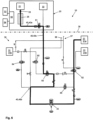
- FIG 3 shows an embodiment of the energy system 10 in the idle state, which serves as a basis for explaining the various methods according to the invention.
- the energy system is based on the Figure 1 illustrated and described energy system 10, so that identical components are provided with identical reference numbers.
- the energy system 10 has an internal system 20 and an external system 30.
- the internal system 20 contains the electrolysis device 21 and the fuel cell device 22, which are connected via a first line section 40b of the connecting line device 40.
- a ventilation device 55 which serves to generate an air flow that dilutes hydrogen escaping in the event of leaks, is connected both to a power supply unit 53 for intended use and to an emergency power supply device 54 in the event of an undesirable power failure.
- the hydrogen generated in the electrolysis device 21 passes through a filter device 25 and a dryer device 26 before it flows through the first line section 40a, leaves the internal system 20 via a first valve device 61 and enters the external system 30 via a line bus 40c of the connecting line device 40.
- the line bus 40c is thus located in the area of the boundary 38 between the internal system 20 and the external system 30.
- the external system 30 has the second line section 40b, which is connected to the first line section 40a of the internal system 20 via the line bus 40c.
- a storage device 31 for storing the hydrogen produced is assigned to the external system 30.
- the storage device 31 has a medium-pressure storage device 31b and two high-pressure storage devices 31a.
- the storage device 31 is either part of the external system 30, or the external system 30 has corresponding interfaces to the storage device 31.
- a fourth valve device 64 is arranged in the immediate vicinity of the medium-pressure storage device 31b, while a second valve device 62 is arranged in the immediate vicinity of the high-pressure storage device 31a.
- a central valve device 60 is arranged in the second line section 40b. In the second line section 40b there is also a compressor device 33 and two further valve devices 63 and 65.
- the various valve devices are preferably shut-off valves, for example solenoid valves.
- the external system 30 has a discharge point 36, which is located in an Ex-Zone-2 37, and through which hydrogen can be discharged from the external system 30.
- the energy system 10 has an emergency power supply device 54. If the emergency power supply device 54 is activated, it activates the necessary components with respect to hydrogen in the internal system 30, here the first valve device 61, via which a safety-related pressure relief takes place.
- the pressure in the electrolysis device 21 is actively reduced according to the method of the first aspect of the invention.
- the first valve device 61 and in particular also a central valve device 60 in the external system 30 are provided.
- the line bus 40c between the internal system 20 and the external system 30 allows the hydrogen to be safely discharged via the discharge point 36 in the external system 30. After the hydrogen has been discharged, there is no longer any need for ventilation in the internal system 20.
- the emergency power supply device 54 can then be deactivated.
- control of the individual components is preferably carried out via a control device which is Figure 4 is not explicitly shown. If the control device detects the failure of the ventilation device 55, the control device automatically activates the emergency power supply device 54 and the required components of the internal system 20 and the external system 30, here the first valve device 61 and the central valve device 60, so that the hydrogen in the first hydrogen system of the internal system 20 is transported from the internal system 20 via the line bus 40c into the external system 30 and to the delivery point 36, wherein the control device deactivates the emergency power supply device 54 and optionally the valve devices 60, 61 after the hydrogen has been discharged via the delivery point 36.
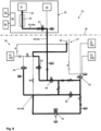
- the energy system 10 is according to Figure 3 shown, using the Figures 5 to 8 the sequence of the method according to the second aspect of the invention is explained.
- explosion protection is created by leak testing and pressure relief in the external system 30.
- the energy system 10 is usually operated in a discontinuous mode of operation in which, due to changing processes, individual components relating to hydrogen in the first hydrogen system in the internal system 20 and/or in the second hydrogen system in the external system 30 are temporarily not used.
- a leak test is carried out, in particular automatically, in those components that are not used. This can in turn be done via a control device (in the Figures 5 to 8 not explicitly shown) of the energy system 10. If the control device detects or receives information that a component or a sub-area of the external system 30 is not currently being used, the control device can initiate a leak test there.
- the first hydrogen system in the internal system 20 and/or the second hydrogen system in the external system 30 can be blocked. This is preferably done via the control device.
- the central valve device 60 can be activated, preferably via the control device, so that the hydrogen in the second hydrogen system of the external system 30 is transported from the external system 30 to the delivery point 36 via the second line section 40b.
- the flow of hydrogen is in the Figures 5 to 8 for different operating states, each shown as a bold line.
- a leak test can be carried out in the areas not shown in bold. For this purpose, the pressure drop over time is determined. If leaks or critical leaks are detected in the different areas, operation can be immediately shut down in order to minimize the critical amount of hydrogen.
- hydrogen can be discharged in a targeted manner via the central valve device 60 and the discharge point 36 if required.
- Figure 6 shows an operating state in which hydrogen is produced in the electrolysis device 21 in the internal system 20, and the hydrogen produced is stored in the high-pressure storage device 31a by means of compression in the compressor 33. If necessary, in a modified operating state, which is not explicitly shown, intermediate storage in the medium-pressure storage device 31b can be carried out in advance, analogous to the Figure 5 shown operating state.
- FIG. 7 shows an operating state in which the hydrogen stored in the high-pressure storage device 31a is removed from it and consumed, here in the fuel cell device 22 assigned to the internal system 20.
- Figure 8 finally shows an operating state in which hydrogen is released via the release point 36 from the overall system, including compressor 33, in order to depressurize the entire hydrogen line system with the connected hydrogen-carrying components, but without the storage units.
Landscapes
- Chemical & Material Sciences (AREA)
- Engineering & Computer Science (AREA)
- Electrochemistry (AREA)
- Chemical Kinetics & Catalysis (AREA)
- Organic Chemistry (AREA)
- Metallurgy (AREA)
- Materials Engineering (AREA)
- Sustainable Energy (AREA)
- General Chemical & Material Sciences (AREA)
- Automation & Control Theory (AREA)
- Life Sciences & Earth Sciences (AREA)
- Sustainable Development (AREA)
- Manufacturing & Machinery (AREA)
- Inorganic Chemistry (AREA)
- Electrolytic Production Of Non-Metals, Compounds, Apparatuses Therefor (AREA)
- Filling Or Discharging Of Gas Storage Vessels (AREA)
- Fuel Cell (AREA)
Applications Claiming Priority (1)
| Application Number | Priority Date | Filing Date | Title |
|---|---|---|---|
| DE102023119435.6A DE102023119435A1 (de) | 2023-07-24 | 2023-07-24 | Vermeidung einer explosionsfähigen Atmosphäre in einem Energiesystem |
Publications (2)
| Publication Number | Publication Date |
|---|---|
| EP4497843A2 true EP4497843A2 (fr) | 2025-01-29 |
| EP4497843A3 EP4497843A3 (fr) | 2025-02-12 |
Family
ID=91959321
Family Applications (1)
| Application Number | Title | Priority Date | Filing Date |
|---|---|---|---|
| EP24189413.8A Withdrawn EP4497843A3 (fr) | 2023-07-24 | 2024-07-18 | Prévention d'une atmosphère explosible dans un système d'énergie |
Country Status (2)
| Country | Link |
|---|---|
| EP (1) | EP4497843A3 (fr) |
| DE (1) | DE102023119435A1 (fr) |
Cited By (1)
| Publication number | Priority date | Publication date | Assignee | Title |
|---|---|---|---|---|
| US12601299B1 (en) * | 2025-04-16 | 2026-04-14 | General Electric Company | Hydrogen fuel system for an aircraft |
Citations (4)
| Publication number | Priority date | Publication date | Assignee | Title |
|---|---|---|---|---|
| WO2015144446A1 (fr) | 2014-03-24 | 2015-10-01 | Siemens Aktiengesellschaft | Alimentation sans interruption d'une installation d'électrolyse |
| WO2017089469A1 (fr) | 2015-11-25 | 2017-06-01 | Hps Home Power Solutions Gmbh | Centrale d'énergie domestique et procédé pour faire fonctionner une centrale d'énergie domestique |
| WO2017089468A1 (fr) | 2015-11-25 | 2017-06-01 | Hps Home Power Solutions Gmbh | Installation d'énergie à domicile et procédé d'exploitation d'une installation d'énergie à domicile |
| WO2020127537A1 (fr) | 2018-12-20 | 2020-06-25 | Hps Home Power Solutions Gmbh | Système de rinçage et procédé permettant de surveiller ledit système |
Family Cites Families (4)
| Publication number | Priority date | Publication date | Assignee | Title |
|---|---|---|---|---|
| US6887601B2 (en) * | 2000-09-28 | 2005-05-03 | Proton Energy Systems, Inc. | Regenerative electrochemical cell system and method for use thereof |
| DE102006058045B4 (de) * | 2006-12-07 | 2012-11-22 | Deutsches Zentrum für Luft- und Raumfahrt e.V. | Überwachungsvorrichtung zur Überwachung und Notfallsteuerung von Elektrolyseeinrichtungen |
| US10144641B2 (en) * | 2015-06-24 | 2018-12-04 | The Boeing Company | System and method for high pressure, passive condensing of water from hydrogen in a reversible solid oxide fuel cell system |
| JP6165972B1 (ja) * | 2015-09-30 | 2017-07-19 | 株式会社東芝 | 水素製造装置及び水素製造システム |
-
2023
- 2023-07-24 DE DE102023119435.6A patent/DE102023119435A1/de not_active Withdrawn
-
2024
- 2024-07-18 EP EP24189413.8A patent/EP4497843A3/fr not_active Withdrawn
Patent Citations (5)
| Publication number | Priority date | Publication date | Assignee | Title |
|---|---|---|---|---|
| WO2015144446A1 (fr) | 2014-03-24 | 2015-10-01 | Siemens Aktiengesellschaft | Alimentation sans interruption d'une installation d'électrolyse |
| WO2017089469A1 (fr) | 2015-11-25 | 2017-06-01 | Hps Home Power Solutions Gmbh | Centrale d'énergie domestique et procédé pour faire fonctionner une centrale d'énergie domestique |
| WO2017089468A1 (fr) | 2015-11-25 | 2017-06-01 | Hps Home Power Solutions Gmbh | Installation d'énergie à domicile et procédé d'exploitation d'une installation d'énergie à domicile |
| EP3380792A1 (fr) | 2015-11-25 | 2018-10-03 | HPS Home Power Solutions GmbH | Centrale d'énergie domestique et procédé pour faire fonctionner une centrale d'énergie domestique |
| WO2020127537A1 (fr) | 2018-12-20 | 2020-06-25 | Hps Home Power Solutions Gmbh | Système de rinçage et procédé permettant de surveiller ledit système |
Cited By (1)
| Publication number | Priority date | Publication date | Assignee | Title |
|---|---|---|---|---|
| US12601299B1 (en) * | 2025-04-16 | 2026-04-14 | General Electric Company | Hydrogen fuel system for an aircraft |
Also Published As
| Publication number | Publication date |
|---|---|
| DE102023119435A1 (de) | 2025-01-30 |
| EP4497843A3 (fr) | 2025-02-12 |
Similar Documents
| Publication | Publication Date | Title |
|---|---|---|
| EP3899096B1 (fr) | Système d'énergie et procédé de surveillance de pression de conduite | |
| EP3899095B1 (fr) | Système d'énergie avec un système de rinçage, et procédé permettant de surveiller ledit système | |
| DE102018133194A1 (de) | Lüftungssystem und Verfahren zu dessen Betrieb | |
| EP4497843A2 (fr) | Prévention d'une atmosphère explosible dans un système d'énergie | |
| EP3321501A1 (fr) | Systeme de stockage et de récupération d'énergie | |
| EP4379876A2 (fr) | Système d'énergie | |
| DE202022105518U1 (de) | Energieversorgungssystem sowie Verwendung des Energieversorgungssystems | |
| EP3900091A1 (fr) | Système énergétique et procédé d'ajustement de pression dans un système énergétique | |
| EP3899094B1 (fr) | Système de rinçage et son utilisation dans un système énergétique | |
| EP3497307A1 (fr) | Centrale à turbine à gaz et à vapeur de cogénération d'électricité et de vapeur | |
| EP4483465A1 (fr) | Dispositif de stabilisation de réseaux électriques comprenant des cavernes pour le stockage du gaz | |
| DE102022114038A1 (de) | Energiesystem | |
| DE102012024791B4 (de) | Dezentraler Stromerzeuger und Inselnetz | |
| DE102018216680B3 (de) | Verfahren zum Rückbau einer großtechnischen Anlage und mobiles Leittechniksystem für den Rückbau derselben | |
| EP3166196B1 (fr) | Centrale électrique, ensemble de centrale électrique comprenant une centrale électrique et procédé de fonctionnement | |
| EP3899348B1 (fr) | Procédé de stockage d'un fluide dans un dispositif de stockage sous pression | |
| EP4570964A1 (fr) | Dispositif de rinçage destiné au stockage intermédiaire d'un milieu gazeux provenant d'un processus de rinçage | |
| DE102022131861A1 (de) | Kondensatablaufeinrichtung und Verfahren zu deren Betrieb | |
| DE102024119147A1 (de) | Verfahren zum Betreiben eines Energiesystems sowie Energiesystem | |
| DE102024119145A1 (de) | Energiesystem und Verfahren zum Betreiben eines Energiesystems | |
| EP4095443A1 (fr) | Dispositif de conversion d'énergie à l'aide d'unité de pile à combustible | |
| EP4170065A1 (fr) | Système de réseau de distribution d'hydrogène | |
| DE102024119148A1 (de) | Verfahren zum Betreiben eines Energiesystems sowie Energiesystem | |
| WO2023227728A1 (fr) | Système d'alimentation électrique, procédé de construction d'un système d'alimentation électrique et utilisation du système d'alimentation électrique | |
| DE102022131679A1 (de) | Energiesystem |
Legal Events
| Date | Code | Title | Description |
|---|---|---|---|
| PUAI | Public reference made under article 153(3) epc to a published international application that has entered the european phase |
Free format text: ORIGINAL CODE: 0009012 |
|
| STAA | Information on the status of an ep patent application or granted ep patent |
Free format text: STATUS: THE APPLICATION HAS BEEN PUBLISHED |
|
| PUAL | Search report despatched |
Free format text: ORIGINAL CODE: 0009013 |
|
| AK | Designated contracting states |
Kind code of ref document: A2 Designated state(s): AL AT BE BG CH CY CZ DE DK EE ES FI FR GB GR HR HU IE IS IT LI LT LU LV MC ME MK MT NL NO PL PT RO RS SE SI SK SM TR |
|
| AK | Designated contracting states |
Kind code of ref document: A3 Designated state(s): AL AT BE BG CH CY CZ DE DK EE ES FI FR GB GR HR HU IE IS IT LI LT LU LV MC ME MK MT NL NO PL PT RO RS SE SI SK SM TR |
|
| RIC1 | Information provided on ipc code assigned before grant |
Ipc: C25B 15/02 20210101ALI20250108BHEP Ipc: C25B 1/02 20060101AFI20250108BHEP |
|
| STAA | Information on the status of an ep patent application or granted ep patent |
Free format text: STATUS: THE APPLICATION IS DEEMED TO BE WITHDRAWN |
|
| 18D | Application deemed to be withdrawn |
Effective date: 20250813 |