EP3899314B1 - Dispositif et système d'amortissement à ressort coaxial - Google Patents
Dispositif et système d'amortissement à ressort coaxial Download PDFInfo
- Publication number
- EP3899314B1 EP3899314B1 EP19898800.8A EP19898800A EP3899314B1 EP 3899314 B1 EP3899314 B1 EP 3899314B1 EP 19898800 A EP19898800 A EP 19898800A EP 3899314 B1 EP3899314 B1 EP 3899314B1
- Authority
- EP
- European Patent Office
- Prior art keywords
- spring
- damper
- directional
- viscoelastic
- viscoelastic damper
- Prior art date
- Legal status (The legal status is an assumption and is not a legal conclusion. Google has not performed a legal analysis and makes no representation as to the accuracy of the status listed.)
- Active
Links
Images


Classifications
-
- F—MECHANICAL ENGINEERING; LIGHTING; HEATING; WEAPONS; BLASTING
- F41—WEAPONS
- F41G—WEAPON SIGHTS; AIMING
- F41G11/00—Details of sighting or aiming apparatus; Accessories
- F41G11/001—Means for mounting tubular or beam shaped sighting or aiming devices on firearms
- F41G11/002—Mountings with recoil absorbing means
-
- F—MECHANICAL ENGINEERING; LIGHTING; HEATING; WEAPONS; BLASTING
- F16—ENGINEERING ELEMENTS AND UNITS; GENERAL MEASURES FOR PRODUCING AND MAINTAINING EFFECTIVE FUNCTIONING OF MACHINES OR INSTALLATIONS; THERMAL INSULATION IN GENERAL
- F16F—SPRINGS; SHOCK-ABSORBERS; MEANS FOR DAMPING VIBRATION
- F16F1/00—Springs
- F16F1/36—Springs made of rubber or other material having high internal friction, e.g. thermoplastic elastomers
- F16F1/371—Springs made of rubber or other material having high internal friction, e.g. thermoplastic elastomers characterised by inserts or auxiliary extension or exterior elements, e.g. for rigidification
-
- F—MECHANICAL ENGINEERING; LIGHTING; HEATING; WEAPONS; BLASTING
- F16—ENGINEERING ELEMENTS AND UNITS; GENERAL MEASURES FOR PRODUCING AND MAINTAINING EFFECTIVE FUNCTIONING OF MACHINES OR INSTALLATIONS; THERMAL INSULATION IN GENERAL
- F16F—SPRINGS; SHOCK-ABSORBERS; MEANS FOR DAMPING VIBRATION
- F16F1/00—Springs
- F16F1/36—Springs made of rubber or other material having high internal friction, e.g. thermoplastic elastomers
- F16F1/373—Springs made of rubber or other material having high internal friction, e.g. thermoplastic elastomers characterised by having a particular shape
-
- F—MECHANICAL ENGINEERING; LIGHTING; HEATING; WEAPONS; BLASTING
- F16—ENGINEERING ELEMENTS AND UNITS; GENERAL MEASURES FOR PRODUCING AND MAINTAINING EFFECTIVE FUNCTIONING OF MACHINES OR INSTALLATIONS; THERMAL INSULATION IN GENERAL
- F16F—SPRINGS; SHOCK-ABSORBERS; MEANS FOR DAMPING VIBRATION
- F16F15/00—Suppression of vibrations in systems; Means or arrangements for avoiding or reducing out-of-balance forces, e.g. due to motion
- F16F15/02—Suppression of vibrations of non-rotating, e.g. reciprocating systems; Suppression of vibrations of rotating systems by use of members not moving with the rotating systems
- F16F15/022—Suppression of vibrations of non-rotating, e.g. reciprocating systems; Suppression of vibrations of rotating systems by use of members not moving with the rotating systems using dampers and springs in combination
-
- F—MECHANICAL ENGINEERING; LIGHTING; HEATING; WEAPONS; BLASTING
- F16—ENGINEERING ELEMENTS AND UNITS; GENERAL MEASURES FOR PRODUCING AND MAINTAINING EFFECTIVE FUNCTIONING OF MACHINES OR INSTALLATIONS; THERMAL INSULATION IN GENERAL
- F16F—SPRINGS; SHOCK-ABSORBERS; MEANS FOR DAMPING VIBRATION
- F16F15/00—Suppression of vibrations in systems; Means or arrangements for avoiding or reducing out-of-balance forces, e.g. due to motion
- F16F15/10—Suppression of vibrations in rotating systems by making use of members moving with the system
- F16F15/12—Suppression of vibrations in rotating systems by making use of members moving with the system using elastic members or friction-damping members, e.g. between a rotating shaft and a gyratory mass mounted thereon
- F16F15/121—Suppression of vibrations in rotating systems by making use of members moving with the system using elastic members or friction-damping members, e.g. between a rotating shaft and a gyratory mass mounted thereon using springs as elastic members, e.g. metallic springs
- F16F15/123—Wound springs
- F16F15/12353—Combinations of dampers, e.g. with multiple plates, multiple spring sets, i.e. complex configurations
-
- F—MECHANICAL ENGINEERING; LIGHTING; HEATING; WEAPONS; BLASTING
- F16—ENGINEERING ELEMENTS AND UNITS; GENERAL MEASURES FOR PRODUCING AND MAINTAINING EFFECTIVE FUNCTIONING OF MACHINES OR INSTALLATIONS; THERMAL INSULATION IN GENERAL
- F16F—SPRINGS; SHOCK-ABSORBERS; MEANS FOR DAMPING VIBRATION
- F16F15/00—Suppression of vibrations in systems; Means or arrangements for avoiding or reducing out-of-balance forces, e.g. due to motion
- F16F15/10—Suppression of vibrations in rotating systems by making use of members moving with the system
- F16F15/12—Suppression of vibrations in rotating systems by making use of members moving with the system using elastic members or friction-damping members, e.g. between a rotating shaft and a gyratory mass mounted thereon
- F16F15/121—Suppression of vibrations in rotating systems by making use of members moving with the system using elastic members or friction-damping members, e.g. between a rotating shaft and a gyratory mass mounted thereon using springs as elastic members, e.g. metallic springs
- F16F15/127—Suppression of vibrations in rotating systems by making use of members moving with the system using elastic members or friction-damping members, e.g. between a rotating shaft and a gyratory mass mounted thereon using springs as elastic members, e.g. metallic springs using plastics springs combined with other types of springs
-
- F—MECHANICAL ENGINEERING; LIGHTING; HEATING; WEAPONS; BLASTING
- F16—ENGINEERING ELEMENTS AND UNITS; GENERAL MEASURES FOR PRODUCING AND MAINTAINING EFFECTIVE FUNCTIONING OF MACHINES OR INSTALLATIONS; THERMAL INSULATION IN GENERAL
- F16F—SPRINGS; SHOCK-ABSORBERS; MEANS FOR DAMPING VIBRATION
- F16F15/00—Suppression of vibrations in systems; Means or arrangements for avoiding or reducing out-of-balance forces, e.g. due to motion
- F16F15/10—Suppression of vibrations in rotating systems by making use of members moving with the system
- F16F15/12—Suppression of vibrations in rotating systems by making use of members moving with the system using elastic members or friction-damping members, e.g. between a rotating shaft and a gyratory mass mounted thereon
- F16F15/131—Suppression of vibrations in rotating systems by making use of members moving with the system using elastic members or friction-damping members, e.g. between a rotating shaft and a gyratory mass mounted thereon the rotating system comprising two or more gyratory masses
- F16F15/133—Suppression of vibrations in rotating systems by making use of members moving with the system using elastic members or friction-damping members, e.g. between a rotating shaft and a gyratory mass mounted thereon the rotating system comprising two or more gyratory masses using springs as elastic members, e.g. metallic springs
- F16F15/137—Suppression of vibrations in rotating systems by making use of members moving with the system using elastic members or friction-damping members, e.g. between a rotating shaft and a gyratory mass mounted thereon the rotating system comprising two or more gyratory masses using springs as elastic members, e.g. metallic springs the elastic members consisting of two or more springs of different kinds, e.g. elastomeric members and wound springs
-
- F—MECHANICAL ENGINEERING; LIGHTING; HEATING; WEAPONS; BLASTING
- F16—ENGINEERING ELEMENTS AND UNITS; GENERAL MEASURES FOR PRODUCING AND MAINTAINING EFFECTIVE FUNCTIONING OF MACHINES OR INSTALLATIONS; THERMAL INSULATION IN GENERAL
- F16F—SPRINGS; SHOCK-ABSORBERS; MEANS FOR DAMPING VIBRATION
- F16F3/00—Spring units consisting of several springs, e.g. for obtaining a desired spring characteristic
- F16F3/08—Spring units consisting of several springs, e.g. for obtaining a desired spring characteristic with springs made of a material having high internal friction, e.g. rubber
- F16F3/10—Spring units consisting of several springs, e.g. for obtaining a desired spring characteristic with springs made of a material having high internal friction, e.g. rubber combined with springs made of steel or other material having low internal friction
-
- F—MECHANICAL ENGINEERING; LIGHTING; HEATING; WEAPONS; BLASTING
- F16—ENGINEERING ELEMENTS AND UNITS; GENERAL MEASURES FOR PRODUCING AND MAINTAINING EFFECTIVE FUNCTIONING OF MACHINES OR INSTALLATIONS; THERMAL INSULATION IN GENERAL
- F16F—SPRINGS; SHOCK-ABSORBERS; MEANS FOR DAMPING VIBRATION
- F16F9/00—Springs, vibration-dampers, shock-absorbers, or similarly-constructed movement-dampers using a fluid or the equivalent as damping medium
- F16F9/30—Springs, vibration-dampers, shock-absorbers, or similarly-constructed movement-dampers using a fluid or the equivalent as damping medium with solid or semi-solid material, e.g. pasty masses, as damping medium
-
- F—MECHANICAL ENGINEERING; LIGHTING; HEATING; WEAPONS; BLASTING
- F41—WEAPONS
- F41G—WEAPON SIGHTS; AIMING
- F41G1/00—Sighting devices
- F41G1/38—Telescopic sights specially adapted for smallarms or ordnance; Supports or mountings therefor
-
- F—MECHANICAL ENGINEERING; LIGHTING; HEATING; WEAPONS; BLASTING
- F16—ENGINEERING ELEMENTS AND UNITS; GENERAL MEASURES FOR PRODUCING AND MAINTAINING EFFECTIVE FUNCTIONING OF MACHINES OR INSTALLATIONS; THERMAL INSULATION IN GENERAL
- F16F—SPRINGS; SHOCK-ABSORBERS; MEANS FOR DAMPING VIBRATION
- F16F1/00—Springs
- F16F1/02—Springs made of steel or other material having low internal friction; Wound, torsion, leaf, cup, ring or the like springs, the material of the spring not being relevant
- F16F1/04—Wound springs
-
- F—MECHANICAL ENGINEERING; LIGHTING; HEATING; WEAPONS; BLASTING
- F16—ENGINEERING ELEMENTS AND UNITS; GENERAL MEASURES FOR PRODUCING AND MAINTAINING EFFECTIVE FUNCTIONING OF MACHINES OR INSTALLATIONS; THERMAL INSULATION IN GENERAL
- F16F—SPRINGS; SHOCK-ABSORBERS; MEANS FOR DAMPING VIBRATION
- F16F1/00—Springs
- F16F1/36—Springs made of rubber or other material having high internal friction, e.g. thermoplastic elastomers
- F16F1/373—Springs made of rubber or other material having high internal friction, e.g. thermoplastic elastomers characterised by having a particular shape
- F16F1/3732—Springs made of rubber or other material having high internal friction, e.g. thermoplastic elastomers characterised by having a particular shape having an annular or the like shape, e.g. grommet-type resilient mountings
-
- F—MECHANICAL ENGINEERING; LIGHTING; HEATING; WEAPONS; BLASTING
- F16—ENGINEERING ELEMENTS AND UNITS; GENERAL MEASURES FOR PRODUCING AND MAINTAINING EFFECTIVE FUNCTIONING OF MACHINES OR INSTALLATIONS; THERMAL INSULATION IN GENERAL
- F16F—SPRINGS; SHOCK-ABSORBERS; MEANS FOR DAMPING VIBRATION
- F16F1/00—Springs
- F16F1/36—Springs made of rubber or other material having high internal friction, e.g. thermoplastic elastomers
- F16F1/373—Springs made of rubber or other material having high internal friction, e.g. thermoplastic elastomers characterised by having a particular shape
- F16F1/377—Springs made of rubber or other material having high internal friction, e.g. thermoplastic elastomers characterised by having a particular shape having holes or openings
-
- F—MECHANICAL ENGINEERING; LIGHTING; HEATING; WEAPONS; BLASTING
- F16—ENGINEERING ELEMENTS AND UNITS; GENERAL MEASURES FOR PRODUCING AND MAINTAINING EFFECTIVE FUNCTIONING OF MACHINES OR INSTALLATIONS; THERMAL INSULATION IN GENERAL
- F16F—SPRINGS; SHOCK-ABSORBERS; MEANS FOR DAMPING VIBRATION
- F16F13/00—Units comprising springs of the non-fluid type as well as vibration-dampers, shock-absorbers, or fluid springs
- F16F13/005—Units comprising springs of the non-fluid type as well as vibration-dampers, shock-absorbers, or fluid springs comprising both a wound spring and a damper, e.g. a friction damper
-
- F—MECHANICAL ENGINEERING; LIGHTING; HEATING; WEAPONS; BLASTING
- F16—ENGINEERING ELEMENTS AND UNITS; GENERAL MEASURES FOR PRODUCING AND MAINTAINING EFFECTIVE FUNCTIONING OF MACHINES OR INSTALLATIONS; THERMAL INSULATION IN GENERAL
- F16F—SPRINGS; SHOCK-ABSORBERS; MEANS FOR DAMPING VIBRATION
- F16F2224/00—Materials; Material properties
- F16F2224/02—Materials; Material properties solids
-
- F—MECHANICAL ENGINEERING; LIGHTING; HEATING; WEAPONS; BLASTING
- F16—ENGINEERING ELEMENTS AND UNITS; GENERAL MEASURES FOR PRODUCING AND MAINTAINING EFFECTIVE FUNCTIONING OF MACHINES OR INSTALLATIONS; THERMAL INSULATION IN GENERAL
- F16F—SPRINGS; SHOCK-ABSORBERS; MEANS FOR DAMPING VIBRATION
- F16F2226/00—Manufacturing; Treatments
- F16F2226/04—Assembly or fixing methods; methods to form or fashion parts
-
- F—MECHANICAL ENGINEERING; LIGHTING; HEATING; WEAPONS; BLASTING
- F16—ENGINEERING ELEMENTS AND UNITS; GENERAL MEASURES FOR PRODUCING AND MAINTAINING EFFECTIVE FUNCTIONING OF MACHINES OR INSTALLATIONS; THERMAL INSULATION IN GENERAL
- F16F—SPRINGS; SHOCK-ABSORBERS; MEANS FOR DAMPING VIBRATION
- F16F2234/00—Shape
- F16F2234/02—Shape cylindrical
-
- F—MECHANICAL ENGINEERING; LIGHTING; HEATING; WEAPONS; BLASTING
- F16—ENGINEERING ELEMENTS AND UNITS; GENERAL MEASURES FOR PRODUCING AND MAINTAINING EFFECTIVE FUNCTIONING OF MACHINES OR INSTALLATIONS; THERMAL INSULATION IN GENERAL
- F16F—SPRINGS; SHOCK-ABSORBERS; MEANS FOR DAMPING VIBRATION
- F16F2236/00—Mode of stressing of basic spring or damper elements or devices incorporating such elements
- F16F2236/04—Compression
Definitions
- Spring mass damper systems such as found in suspension systems of vehicles, are well known and widely used. Such systems typically have a mechanical spring element and a damping element, such as a mechanical coil spring operable with a fluid (gas) damper mechanism. In typical systems, as the coil spring reaches its maximum working range, the fluid damper mechanism operates (in conjunction with the coil spring) to dampen shock between two bodies or structures (e.g., vehicle frame and vehicle axles). However, the fluid damper device can as a secondary spring to the primary (coil) spring, thereby affecting or modifying the spring rate of the primary spring. Such "dual spring" configuration is not useful or ideal in other applications, such as applications involving a shock impulse event while still requiring some amount of damping effect from a damper element.
- a "crash pad” with a coil spring, such as a foam or rubber bushing or other component positioned proximate one end of the coil spring, so that when the coil spring reaches or exceeds its maximum working range limit (such as from an impulse shock event), the crash pad acts to stop or inhibit movement of the spring (to prevent it from “bottoming out”).
- foam or rubber "crash pads” absorb some amount of energy from the impulse shock event through deformation of the foam or rubber crash pad (e.g., converting mechanical energy to heat), but they do not help or operate to dampen resonant vibration between two structures or bodies between which the spring is situated.
- one or more directional springs e.g., coil springs
- the springs operate to attenuate shock from an impulse shock event to avoid shock to one of the bodies.
- This configuration can be effective at removing backlash or play between the bodies when the position of one body is adjusted relative to the other body (e.g., such as when making micro adjustments in the position of an optics device, such as a scope, relative to the stock/body of the firearm to which the optics device is mounted).
- US 2017/175848 A1 discloses a torsional damper assembly for a vehicle powertrain that is configured to dampen torsional vibration transfer between an engine and a transmission of the vehicle.
- the assembly includes a hub having a flange defining a window, a biasing mechanism disposed at least partially within the window and configured to absorb a first portion of the torsional vibration from the engine, and a damper body disposed at least partially within the window.
- the damper body is formed from at least one of a viscoelastic material and a viscoplastic material, and is configured to dampen a second, different portion of the torsional vibration and radial forces from the engine such that the biasing mechanism and the damper body cooperatively dampen the torsional vibration transfer between the engine and the transmission.
- US 5 425 191 A discloses a telescopic gun sight that is clamped to a mount which is mounted on a base for limited relative sliding movement fore and aft of the barrel of a rifle, to which the base is secured.
- Resilient bushes of elastomeric material are disposed within bores in the mount, and fixing bolts pass through the bushes to clamp the mount to the base.
- the resilience of the bushes allows the mount to move slightly relative to the base, and returns the mount to its original datum position after such movement. In this way, shocks that may otherwise damage the sight and/or shift its position relative to the barrel of the rifle may be absorbed-particularly recoil shocks upon firing.
- relative movement of a mount relative to a base is possible in more than one direction, thereby to absorb shocks in other directions, as may be caused by, for example, accidental knocks.
- JP 2013 108518 A discloses a vibration control fixing member having high vibration damping effects.
- the vibration control fixing member includes a viscous elastomer member formed of a viscous elastomer, pairs of fixing ends mounted to both ends of the viscous elastomer member, respectively, and an elastic member mounted at both ends to the pairs of fixing ends.
- the vibration control fixing member is used in applications where ones of the pairs of fixing ends are fixed to an external member and the others are fixed to another external member so that the external members is fixed to one another.
- the viscous elastomer member and the elastic member have no contact with each other at others than the fixing ends.
- the present disclosure provides a spring damper device, comprising: a directional spring having first and second ends, and defining an inner diameter region; and a viscoelastic damper comprising a viscoelastic polymer comprising both an element of viscosity and an element of elasticity, and configured to extend from the first end to the second end of the directional spring to be situated within the inner diameter region of the directional spring, the viscoelastic damper comprising a first section having a first diameter, a second section having a second diameter, and a third section having a third diameter, wherein the first and third diameters are substantially the same and are each less than the second diameter, and wherein the first and third sections are formed on opposing sides of the second section, wherein, in response to a load on the spring damper device, the directional spring operates to compress to absorb the load and any impact shock associated with the load, and the viscoelastic damper operates to dampen vibration associated with the load, wherein the viscoelastic damper is sized
- the present disclosure provides a method for making a spring damper device, comprising: providing a directional spring having first and second ends, and defining an inner diameter region; and forming a viscoelastic damper comprising a viscoelastic polymer comprising both an element of viscosity and an element of elasticity, the viscoelastic damper being configured to extend from the first end to the second end of the directional spring and be situated within the inner diameter region of the directional spring, the viscoelastic damper comprising a first section having a first diameter, a second section having a second diameter, and a third section having a third diameter, wherein the first and third diameters are substantially the same and are each less than the second diameter, such that the first and third sections are formed on opposing sides of the second section, wherein, in response to a load on the spring damper device, the directional spring operates to compress to absorb the load and an impact shock associated with the load, and the viscoelastic damper operates to dampen at least one of
- the present disclosure provides a method for assembling a spring damper system, comprising: providing a first structure having a plurality of spring seats, and a second structure having a plurality of spring seats, wherein the second structure is movable relative to the first structure; situating a plurality of spring damper devices against respective spring seats of the first structure, wherein each spring damper device comprises a directional spring and a viscoelastic damper situated within an inner diameter region of the directional spring, the viscoelastic damper comprising a viscoelastic polymer, the viscoelastic polymer comprising both an element of viscosity and an element of elasticity, and the viscoelastic damper comprising a first section having a first diameter, a second section having a second diameter, and a third section having a third diameter, wherein the first and third diameters are substantially the same and are each less than the second diameter, such that the first and third sections are formed on opposing sides of the second section, wherein the viscoel
- the term “substantially” refers to the complete or nearly complete extent or degree of an action, characteristic, property, state, structure, item, or result.
- an object that is “substantially” enclosed would mean that the object is either completely enclosed or nearly completely enclosed.
- the exact allowable degree of deviation from absolute completeness may in some cases depend on the specific context. However, generally speaking the nearness of completion will be so as to have the same overall result as if absolute and total completion were obtained.
- the use of “substantially” is equally applicable when used in a negative connotation to refer to the complete or near complete lack of an action, characteristic, property, state, structure, item, or result.
- adjacent refers to the proximity of two structures or elements. Particularly, elements that are identified as being “adjacent” may be either abutting or connected. Such elements may also be near or close to each other without necessarily contacting each other. The exact degree of proximity may in some cases depend on the specific context.
- the present disclosure sets forth a spring damper device comprising a directional spring having first and second ends, and defining an inner diameter region, and a damper comprising an element of elasticity, and configured to be situated within the inner diameter region of the directional spring.
- the directional spring operates to compress to absorb the load and any impact shock associated with the load, and the damper operates to dampen vibration associated with the load.
- the damper comprises a viscoelastic damper comprising both an element of viscosity and the element of elasticity.
- the damper is coaxially aligned with the directional spring.
- the directional spring comprises a coil spring and the inner diameter region is defined by an inner diameter of the coil spring, and the damper is sized to be entirely situated within the inner diameter region of the coil spring.
- the directional spring comprises a first height when uncompressed, and wherein the damper comprises a second height when uncompressed, wherein the first height is greater than the second height, such that the damper is contained with a working range of the directional spring.
- the damper is substantially coaxially aligned with the directional spring.
- the present disclosure sets forth a system for absorbing shock and damping vibration comprising a first structure having a spring seat, a second structure having a spring seat, such that the second structure is positioned opposite the first structure, and at least one spring damper device situated between the first and second structures, the at least one spring damper device comprising a directional spring having a first end positioned against the spring seat of the first structure, and a second end positioned against the spring seat of the second structure.
- the directional spring can define an inner region, such as an inner diameter region, depending upon the shape of the spring.
- a damper comprises an element of elasticity, and can be situated within the inner diameter region of the directional spring. In response to a load on the directional spring from the second structure, the directional spring operates to compress to absorb the load and an impact shock associated with the load, and the damper operates to dampen vibration associated with the load.
- the damper comprises a viscoelastic damper comprising both an element of viscosity and the element of elasticity
- the directional spring and the viscoelastic damper can be at least partially compressed to comprise a pre-load between the first and second structures, such that the directional spring operates to absorb an impulse shock event while the viscoelastic damper operates to attenuate vibration.
- the spring seat of the first structure comprises a bore sized and shaped corresponding to the directional spring, and the first end of the directional spring and at least part of the damper are received and situated within the bore, such that the directional spring and the bore cooperatively operate as structural support for the directional spring.
- the system comprises a plurality of spring damper devices situated between the first and second structures, each of the plurality of spring damper devices comprising a directional spring and a viscoelastic damper situated within the directional spring, respectively, to define a plurality of spring damper devices.
- the plurality of spring damper devices can be at least partially compressed to comprise a pre-load between the first and second structures.
- the first structure comprises a sight mount of a projectile firing mechanism
- the second structure comprises a sight device mounted to the projectile firing mechanism via the sight mount.
- the plurality of directional springs are operable to account for positional adjustments of the sight device relative to the projectile firing mechanism
- the plurality of viscoelastic dampers are operable to attenuate vibration to the sight device in response to a firing event.
- the present disclosure sets forth a method for making a spring damper device comprising providing a directional spring having first and second ends, and defining an inner diameter region, and forming a damper comprising an element of elasticity, and configured to be situated within the inner diameter region of the directional spring.
- the directional spring operates to compress to absorb the load and an impact shock associated with the load, and the damper operates to dampen vibration associated with the load.
- the present disclosure sets forth a method for assembling a spring damper system comprising providing a first structure having a plurality of spring seats, and a second structure having a plurality of spring seats (where the second structure is movable relative to the first structure).
- the method comprises situating a plurality of spring damper devices against respective spring seats of the first structure (each spring damper device comprising a directional spring and a damper situated within an inner diameter region of the directional spring).
- the method comprises preloading the plurality of spring damper devices and the system in which they operate by positioning the second structure adjacent the first structure, such that the plurality of spring damper devices are biased against respective spring seats of the second structure to be in a pre-loaded state.
- each directional spring operates to attenuate an impulse shock between the first and second structures, and each damper operates to dampen vibration between the first and second structures while in the pre-loaded state.
- the method further comprises adjusting a position of the second structure relative to the first structure, such that at least one of the directional springs accounts for the adjusted position by exerting a biasing force associated with the preloaded force of the spring damper device.
- a spring damper device 100 can comprise a directional spring 102 (e.g., a coil spring) having a first end 104a and a second end 104b, and that can define an inner diameter region 106.
- the spring damper device 100 can comprise a damper 108 comprising an element of elasticity, and that can be configured to be situated within the inner diameter region 106 of the directional spring 102.
- the damper 108 can comprise a viscoelastic polymeric damper comprised of an element of elasticity and an element of viscosity.
- the directional spring 102 operates to compress to absorb the load and any associated impulse shock, and the damper 108 operates to dampen or attenuate vibration associated with the load and oscillations of the spring 102.
- the spring damper device 100 can be particularly advantageous in applications or systems where one or more spring damper device(s) is/are at least partially pre-compressed or preloaded, so that the system in which they operate is preloaded, and so that the spring (e.g., 102) can assist to apply a nominal biasing force (e.g., for accounting for adjustments between two structures) and can absorb an impulse shock event (e.g., FIGS. 2C and 3 ), while the damper 108 acts as a damping device that dampens vibration and/or resonance between two structures or bodies of a system (see the discussion of FIG. 3 regarding a firearm sight mounted to a firearm, where the spring damper devices operate in this manner).
- the spring e.g. 102
- the damper 108 acts as a damping device that dampens vibration and/or resonance between two structures or bodies of a system (see the discussion of FIG. 3 regarding a firearm sight mounted to a firearm, where the spring damper devices operate in this manner).
- the dampers exemplified herein can have particularly advantageous properties as a damper situated within an inner diameter region of a directional spring, and being pre-loaded, in one example.
- the term "viscoelastic” refers to any material that exhibits properties of both liquids (viscous solutions) and solids (elastic materials). Thus, a viscous material deforms under load and transmits forces in all directions, and distributes a small amount of pressure over a large area, but does not recover its shape when a load is removed (i.e., the time at which the load is immediately removed).
- an elastic material deforms under load and returns to its original shape when that load is removed.
- a viscoelastic polymer component can concurrently exhibit desirable characteristics of both a liquid and an elastic material (i.e., deforming under a load and transmitting forces in all directions, and recovering to its original shape when the load is removed).
- a viscoelastic polymer damper or element it deforms somewhat like water, and then behaves more like an elastic material as it reaches its maximum or designed deformation limit.
- Viscoelastic polymers (such as those marketed under the registered trademark "Sorbothane” by Sorbethane, Inc.,) combine shock absorption, good memory, vibration isolation and vibration damping characteristics. While many materials exhibit one or more of these characteristics, a viscoelastic polymer combines them into a stable material with a long fatigue life and a relatively low creep rate compared to other polymers (rubber, neoprene, silicone, etc.). A viscoelastic polymer has a relatively high damping coefficient over a very wide temperature range as compared to any other polymer, such as from -20° to +160° Fahrenheit.
- a viscoelastic polymer can absorb shocks efficiently for millions of cycles. Viscoelastic polymers can absorb over 50 percent of vibration energy over most or all of its temperature operating range at frequencies from 10 to 30000 Hz, in some examples, depending upon the configuration of the viscoelastic polymer.
- durometer is a measure of hardness used for polymers. A higher durometer is a frequent indicator of a stronger polymeric material. However, viscoelastic polymers are softer than rubber and most other polymers. Viscoelastic polymers can be formed or cast from 30 to 70 durometer on a Shore 00 scale, but can vary below 30 (while sacrificing strength) or above 70 (while limiting viscoelastic properties).
- the spring 102 has an inner diameter ID, an outer diameter OD, and a height H (at free length).
- the inner diameter region 106 can be a space or void defined by the inner diameter ID and the height H.
- the inner diameter region 106 can generally be a cylindrical, three dimensional shape or void that is bounded vertically between the first and second ends 104a and 104b, and laterally by the distance defined by the inner diameter ID of the spring 102 along any point of the inner circumference of the spring 102.
- the damper 108 can be entirely situated within the inner diameter region 106.
- the damper 108 can be configured, such that it does not substantially (or at all) contact the inner surfaces of the spring 102 while being compressed, so that the spring 102 does not impinge or pinch the damper 108, or in other words, so that the damper 108 does not bind the spring 102 during compression and expansion of the spring 102 and the spring damper device 100.
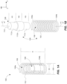
- the damper 108 can be substantially coaxially aligned with the directional spring 102. That is, the damper 108 can have a longitudinal central axis X1 that extends through a center portion 110 of the damper 108, and the spring 102 can have a longitudinal central axis X2 that extends through a centroid or center point of the spring 102 (and consequently through a center point of the inner diameter region 106). As illustrated in FIG. 1B , the longitudinal central axes X1 and X2 are substantially coaxially aligned relative to each other.
- a particular spring damper device contemplated herein can comprise a center compression spring with an array of visco-elastic dampeners spaced around the compression spring (such that the compression spring is coaxial with a central axis defined by the array of visco-elastic dampeners).
- a particular spring damper device as contemplated herein can include a singular visco-elastic dampener having an array of compression springs situated around the dampener (such that the visco-elastic dampener is coaxial with a central axis defined by the array of springs).
- the various spring damper devices contemplated herein can be relatively compact or low profile to suit particular design requirements, because they can have a coaxial configuration that consumes or requires less space than traditional configurations for damping and absorbing impact loads.
- the damper 108 can be formed as a slug, meaning that it can be formed from a uniform, single or solid piece or slug of viscoelastic polymeric material. This is advantageous because solid dampers are more resistant to off-axis loading in cases when additional or incidental shock is encountered (e.g., if a device, such as a weapon is dropped or stored unrestrained and transported being exposed to both shock and vibration profiles). Note that in some instances, it may be desirable to have a damper of the present disclosure retained mechanically or chemically with adhesive on one or both end surfaces of the damper, which may provide some level of retention to keep the damper in a desired position.
- FIG. 1B shows that the damper 108 can comprise a first section 112a having a first diameter D1, a second or mid-section 112b having a second diameter D2, and a third section 112c having a third diameter D3.
- the first and third sections 112a and 112c extend from opposite sides of the second section 112b.
- the first and third diameters D1 and D3 of the first and third sections 112a, 112c, respectively can be substantially the same, and can each be less than the second diameter D2 of the second or mid-section 112b.
- the first and third sections 112a, 112c can be different diameters from one another and from the second section 112b, or both.
- the first, second and third sections 112a-c can comprise any diameter desired, and any two or more diameters can be the same or none of them can be the same.
- first section 112a and the third section 112c can have substantially the same heights H1 and H3, and can be substantially the same as height H2 of the second section 112b.
- first and third sections 112a, 112c, respectively can comprise different heights from each other, as well as from the second section 112b, or both.
- first, second and third sections 112a-c can comprise any height desired, and any two or more heights can be the same or none of them can be the same.
- the damper 108 is shown as being symmetrical about the xyz axes. This is beneficial because such symmetry accepts a shock load by allowing the energy to be absorbed then dissipated in a more balanced and uniformed reaction.
- a symmetrical damper provides a more predictable response derived from the shape of the damper (e.g. a cylindrical shape having a 360° dispersion of energy). Note that a square shape may allow more energy to be released along the surfaces and less at the corners.
- the second section 112b being sized wider or larger in diameter than the adjacent first and third sections 112a and 112c, can assist to properly position the damper 108 within the spring 102, so that it does not shift off-axis too much, or lean or sit in one direction along the y axis (i.e., it helps to center the damper 108 relative to the spring 102, so that it remains substantially coaxial during operation).
- the diameter of the second section 112b can be slightly less than or smaller than the inner diameter ID of the spring 102 (e.g., less than 10 percent smaller).
- FIGS. 2A-2C illustrate a system 120 for absorbing an impact shock event and for damping vibration, the system utilizing the spring damper device 100 (e.g., with spring 102 and damper 108).
- the system 120 can comprise a first structure 122a having a spring seat 124a, and a second structure 122b having a spring seat 124b.
- the second structure 122b can be positioned opposite the first structure 122a, and the first structure 122a can be operable to move toward (and away from) the second structure 122b, whether axially or radially, such as during a shock event.
- the spring seat 124a can comprise a planar surface as shown, that supports or interfaces with the first end 104a of the spring 102, while the spring seat 124b can comprise a bore or recess that supports or interfaces with the second end 104b of the spring 102.
- the spring 102 is shown in its free length position, meaning that little or no compression force is applied to the spring 102.
- the damper 108 is in an uncompressed position or state in FIG. 2A , and is resting against the second structure 122b due to gravity, for instance, if the spring damper device 100 is situated generally vertically relative to earth.
- the spring 102 comprises the first height H when uncompressed or at its free length
- the damper 108 comprises a second height H4 when uncompressed or at its free length.
- the first height H is greater than the second height H4, such that the damper 108 is contained within a working range of the directional spring 102.
- the second height H4 is greater than half the height H of the spring 102 when in the free length.
- varying heights of the damper are contemplated herein, depending on the particular design requirements.
- a load or force F1 is being applied to the spring damper device 100 from the first structure 122a (but can be from the second structure 122b, or both), which load or force F1 partially compresses the spring 102 between the first and second structures 122a and 122b.
- the first structure 122a is further in contact with and is partially compressing the damper 108 (the damper 108 already being seated against the second structure 122b).
- the damper 108 is somewhat smashed and expanded as compared to its initial uncompressed state as shown in FIG. 2A .
- the first and third sections 112a and 112c of the damper 108 expand radially outwardly to a greater degree or rate than that of the second section 112b. This is also because the first and third sections 112a and 112c are initially contacted or compressed by respective first and second structures 122a and 122b, so they transfer mechanical energy to thermal energy prior to that of the second section 122b.
- the first and third sections 112a and 112c expand and deform somewhat like a fluid during the initial compression of the damper 108, so that the second section 122b is limited in outward radial expansion because of the geometry and viscoelastic characteristics of the first and third sections 122a and 122c.
- the system 120 can remain generally static, such as in a pre-loaded system (see e.g., FIG. 3 ). From this configuration or state, as illustrated in FIG. 2C , the system 120 can benefit from absorbing an impulse shock event from the first structure 122a via the spring 102 (because the spring 102 and the damper 108 can further compress to the position in FIG. 2C ), and can concurrently benefit from attenuating vibration and/or resonance via the damper 108, because the damper 108 is more fully compressed between the first and second structures 122a and 122b from its state as shown in FIG.
- Prior devices like fluid dampers, or foam or rubber "crash pads", are fundamentally designed as a secondary spring, and not as a damper to attenuate the high frequencies of vibrations and resonance. Thus, prior dampers can negatively affect the spring rate of a primary (coil) spring at the end of travel of the primary spring, which consequently affects the system as a whole.
- a substantial amount of vibrational energy (and/or resonate energy) is prevented from reaching the second structure 122b, because the pre-compressed damper 108 converts it to thermal energy for dissipation therefrom, without affecting the spring rate of the spring 102, as further discussed herein.
- the profile of the damper 108 can transition from having a non-uniform outer surface and non-uniform cross-sectional area along its longitudinal center axis x1( FIG. 2B ) to a generally uniform outer surface and uniform cross-sectional area along its longitudinal center axis x1 when compressed to or near its maximum compression limit, as shown in FIG. 2C .
- the second section 112b does not expand outwardly to any appreciable degree, unlike the first and third sections 112a and 112c, which expand outwardly a greater degree as the damper 108 is compressed near or at its maximum compression limit.
- the damper 108 can be configured such that it does not contact or interface with the inner surface of the coil of the spring 102, which results in the damper 108 not binding the spring 102, thereby not substantially affecting the spring rate of the spring 102.
- an inner coil spring or other spring element
- the second smaller spring is then compressed, and thereby acts as a backup or secondary spring that affects or changes the spring rate of the larger coil spring and the system.
- the damper 108 acts as a damper to dampen or attenuate vibration and/or resonance, and to not substantially affect operation or the spring rate of the spring 102 that acts to absorb an impact shock independent of the operation of the damper 108. Therefore, during operation, the damper 108 does not substantially change or affect or impede the spring rate of the spring 102, because the damper 108 is formed of a viscoelastic polymer, and tailored (shaped and sized) so that, when compressed, it does not contact or interface with the spring 102 to bind or slow or stop movement of spring (or if the damper 108 does contact the spring 102, such contact is incidental and does not, or is ineffective to, change or modify the spring rate of the spring 102).
- the damper 108 can be sized and configured so that upon maximum compression of the spring 102, the damper 108, while also compressed, does not push beyond the boundary defined by the inner diameter of the spring 102 into the spaces between the coils of the spring 102 where they might be contacted (e.g., pinched) by compressing coils of the spring 102.
- the spring 102 can act, at least partially, as its own structural support for the spring damper device 100. Specifically, because the second end 104a of the spring 102 is situated in and against the spring seat 124b being a bore, sides of the spring 102 can be supported by the sidewall of the bore to prevent the spring damper device 100 from sliding or falling out of the spring seat 124b. This avoids the inclusion of support components that are typically required in many traditional spring systems, such as vehicle spring systems and others that require a number of brackets, fasteners, clamps, etc. to hold or seat a spring in-place.
- the spring damper device 100 can be designed in a particular manner to optimize shock absorbed by the spring 102, and vibration attenuated or damped by the damper 108.
- the variables for designing a particular directional spring e.g., 102 can include the spring constant, the material, the free length, the inner diameter, the coil diameter, etc.
- the variables for designing a particular damper can include the durometer, the shape, the size, the type of viscoelastic polymer, the height relative to the spring free length, diameter(s), and others as will be recognized.
- the directional spring can be designed so that it does not “bottom out” from the known or predicted shock impulse event, while the damper can be designed to not “bottom out” from the maximum predicted shock load, and to not “bind up” the spring when compressed and uncompressed within its predicted working range.
- FIG. 3 illustrates one such example of a system 201 where a spring damper device 200 (similar or the same as the spring damper device 100 discussed above) is preloaded or pre-compressed between a first structure 222a and a second structure 222b, such that the first and second structures are under a preload, or are in a preloaded state.
- preloaded this means that the spring damper device 200 is in a default or nominal position or state where it is at least partially compressed between first and second structures, such that a directional spring 202 and a damper 208 are both compressed to some degree due to a load between the first and second structures (i.e., the first and second structures are in a preloaded state or condition).
- the first structure 222a can be a structural component of a projectile firing mechanism, such as a sight mount of a firearm, and the second structure 222b can be part of a sight device or assembly mounted to the firearm via the sight mount.
- Types of sight devices can include, but are not limited to optical/optics sights (e.g., a telescopic sight, commonly referred to as a scope, a reflector sight, a collimator sight, a holographic sight, a laser sight), as well as other types of sights, such as a thermal weapon sight, a night vision sight, and others.
- optical/optics sights e.g., a telescopic sight, commonly referred to as a scope, a reflector sight, a collimator sight, a holographic sight, a laser sight
- other types of sights such as a thermal weapon sight, a night vision sight, and others.
- an optics type of sight will be discussed in more detail, although such is merely intended to be exemplary
- an optical/optics sight device or assembly mounted to a firearm it is desirable to absorb shock when firing a projectile (i.e., a shock impulse event), so that the optical sight assembly is not damaged or affected due to the shock event that occurs at firing, but at the same time it is also desirable to dampen vibrations and/or resonance so that the sensitive optical sight assembly does not resonate and/or vibrate for an undesirable duration of time after firing (or from resonate frequencies due to electrical devices, human interaction, or other external forces that cause resonance).
- a projectile i.e., a shock impulse event
- the spring 202 can account for and accommodate such positional adjustments, whether in compression or expansion along the x axis, which accounts for the relative distance and relative movement between the first and second structures 222a and 222b (sometimes referred to as "play") while being adjusted in position relative to each other.
- Making adjustments to the relative position of the first and second structures 222a,222b can also function to vary the preload.
- the system may be designed so that the maximum adjustment range of the spring 202 may be limited, such that the damper 208 is prevented from becoming separated (i.e., out of contact) from the first structure 222a, which could defeat the purpose of damping vibration between the first and second structures 222a and 222b.
- the first structure 222a may operate to rotate about the y axis relative to the second structure 222b, as illustrated by the rotational arrows around axis y1, such as is the case when making micro adjustments of the optical sight relative to the firearm.
- the spring 202 in response to an anticipated shock impulse event or load F3 from the first structure 222a to the second structure 222b, the spring 202 will compress and the damper 208 will compress a certain degree (see e.g., FIG. 2C ). Because the load F3 is known or predictable, and because the spring damper device 200 is predesigned to absorb the known or predictable load and attenuate vibrations corresponding to such load, the spring 202 will compress a known or predictable distance (but not "bottom out"), and the damper 208 will also compress a known or predicable amount by deforming while transferring mechanical energy to thermal energy to dampen or attenuate vibration and/or resonance between the first and second structures 222a and 222b.
- a spring seat 224a of the first structure 222a can comprise a planar surface as shown.
- the spring seat 224a can comprise or be configured as a counter bore (similar to spring seat 224b) having any desired or needed depth.
- the spring seat 224b of the second structure 222b can comprise or be configured as a counterbore that has a depth D.
- the counter bore depth can be at least 50 percent a free length or height of the spring 202 (see e.g., height H of spring 102). However, this relationship may vary to achieve counter bore depths that are more or less than this depending on the particular design of the system.
- a shallower counter bore having a depth that is less than 50 percent of the length of the spring may be acceptable (see e.g., FIG. 2A ).
- seating the spring 202 and damper 208 in a counter bore allows the spring damper device 200 to act as its own support structure, so that additional fastening or mounting components are not needed or required to retain the position of the spring 202 and damper 208 during operation.
- the counter bore limits lateral movement of the spring damper device 200. This may be particularly advantageous where available space in a system is limited, and where the spring may only be a few millimeters in free length, such as may be the case with a micro adjustment system of a sight device mounted to a firearm.
- a plurality of spring damper devices may be incorporated into a particular system to absorb shock and attenuate vibration along different axes.
- the system 201 comprises a second or supplemental spring damper device 250 shown situated in or against the first structure 222a (in a cross sectional view of the first structure 222a and the spring damper device 250).
- the second supplemental spring damper device 250 can be situated or oriented along a different axis (e.g., the central axis of the second spring damper device 250 being oriented along the Z axis) than that of the first spring damper device 200 (the central axis of the first spring damper device 200 being oriented along the X axis).
- the second spring damping device 250 can be said to be oriented transverse or generally orthogonal relative to the spring damper device 200 (i.e., the central axes of each spring damper device 200 and 250 can extend along different axes that are transverse or orthogonal relative to each other).
- the second or supplemental spring damper device 250 may be seated between the first and second structures 222a and 222b similarly as the spring damper device 200, as shown. Accordingly, the spring damper device 250 can also include a directional spring 252 (coil) and a damper 258 (viscoelastic polymer damper) situated within an inner diameter region of the spring 252 (similar as spring damper devices 100 and 200). Thus, the spring damper device 250 may be situated in a counterbore or spring seat 264 of the first structure 222a (with the other end of the spring 252 being seated against a spring seat (out of view) of the second structure 222b, or another structure).
- the second structure 222b may be a complex three dimensional support structure, wherein a portion of the second structure 222b extends near or adjacent the spring damper device 250, which portion comprises a spring seat for seating the spring 252.
- the first structure 222a e.g., the firearm sight
- the second structure 222b e.g., the firearm sight mount
- the springs of the damper devices 200, 250 expand and/or compress to account for movement resulting from such micro adjustments (which may or may not vary the preload).
- This can also account for or remove any backlash or "play” or undesirable wiggle/movement between the first and second structures 222a and 222b.
- preloaded springs in prior systems can be effective at removing such backlash or play in an adjustment mechanisms, but often such prior systems suffer from creating an "underdamped" system, which is problematic with high/impulse shock systems like a projectile firing system because resonate vibrations transfer to the optical device, for instance, which can cause damage to the optical device, thereby affecting performance and proper use of the optical device.
- more than two spring damper devices can be incorporated into the system 201 (or an other system), such as between 3 and six spring damper devices, where each of the plurality of spring damper devices are preloaded, as described above.
- the system comprises six spring damper devices
- three of the six spring damper devices can be situated generally parallel to each other and oriented along an x axis (i.e., situated like spring damper device 200), and distributed about particular areas between the first and second structures 222a and 222b in a preloaded configuration.
- the remaining three of the six spring damper devices can be situated parallel to each other and oriented along a z axis (i.e., parallel to the spring damper device 250), and distributed about particular areas between the first and second structures 222a and 222b in a preloaded configuration.
- Each of the plurality of spring damper devices (six in this case) can be designed to function with each of the other spring damper devices and the corresponding structures that support them to achieve the desired performance.
- the spring e.g., springs 102,202
- the spring can be made or configured on a micro scale, such as having an outer spring diameter from 2 mm to 10 mm (but this micro range can vary, and other micro diameters are contemplated).
- the diameter of the counterbore of the spring seat 224b can be slightly larger, such as 3.05 mm or greater, so that the spring 202 is retained in and by the counterbore (i.e., the sidewall of the counterbore would be immediately adjacent the outer surfaces of the spring, so that the spring does not substantially move laterally, or rotationally).
- the ratio of the diameter of the counter bore to the outer spring diameter in this case is 3.05:3 or 1.02.
- the counter bore for the spring 252 can be similarly sized and configured using a similar ratio.
- the cross-sectional area (e.g., diameter) of the counter bore of the spring seat of the structure designed to receive and retain the spring can be configured to be larger than the outer diameter of the spring in accordance with any desired and operable ratio.
- the ratio between the counter bore diameter and the outer spring diameter can be between 1.01 and 1.05 depending upon the system in which the spring damper is intended for use. However, this is not intended to be limiting in any way.
- Providing spring damper devices on a micro or miniature scale can further mean that such devices can have in outer diameter on the order of 2.5mm to 5mm, for instance (or even less than 2.5mm).
- spring damper devices taught herein can be used in a number of different types of systems in addition to the projectile firing system or mechanism (e.g., firearm) discussed herein. Indeed, some example systems in which the spring damper devices as taught herein can be utilized include, but are not limited to, any suitable commercial or military sighting system for hand held firearms, armored fighting vehicles, and vision systems for monitoring industrial applications in harsh environments or in product validation test applications.
- FIG. 4 illustrates a spring damper device 400 in accordance with an example of the present disclosure.
- the spring damper device 400 is shown in an uncompressed position, and can be incorporated in the systems described herein, or in any other system.
- a damper 408, situated within a spring 402 can comprise a cylindrical shaped, uniform slug comprised of a viscoelastic polymer material.
- the spring damper device 400 can be designed similarly as described above, and can have the same or similar advantages and benefits of the other spring damper devices discussed herein.
- FIG. 5 illustrates a spring damper device 500 in accordance with an example of the present disclosure.
- the spring damper device 500 is shown in an uncompressed position, and can be incorporated in the systems described herein, or in any other system.
- a damper 508, situated within a spring 502 can comprise a non-uniform shaped slug comprised of a viscoelastic polymer material.
- the damper 508 comprises an "I-shaped" 2D cross sectional profile, as shown, which is somewhat an inverse profile of the damper 108 of FIG. 2A .
- the spring damper device 500 can be designed similarly as described above, and can have the same or similar advantages and benefits of the other spring damper devices discussed herein.
- FIG. 6 illustrates a spring damper device 600 in accordance with an example of the present disclosure.
- the spring damper device 600 is shown in an uncompressed position, and can be incorporated in the systems described herein, or in any other system.
- a damper 608, situated within a spring 602 can comprise a frustoconical shaped slug comprised of viscoelastic polymer material, and having a trapezoidal 2D cross sectional profile (in another arrangement, the slug can be inverted so that the thicker section is above the smaller section).
- the spring damper device 600 can be designed similarly as described above, and can have the same or similar advantages and benefits of the other spring damper devices discussed herein.
- FIG. 7 illustrates a spring damper device 700 in accordance with an example of the present disclosure.
- the spring damper device 700 is shown in an uncompressed position, and can be incorporated in the systems described herein, or in any other system.
- a damper 708, situated within a spring 702 can comprise a curvilinear shaped slug comprised of a plurality of viscoelastic polymer materials, and having a curved 2D cross-sectional profile.
- the damper 708 can include a plurality of sections 712a-c situated adjacent one another (in this view stacked on each other), with at least two of the sections (or all three of the sections) comprising a different type of viscoelastic polymer material (e.g., having different durometers).
- the spring damper device 700 can be designed similarly as described above, and can have the same or similar advantages and benefits of the other spring damper devices discussed herein.
- FIG. 8 illustrates a spring damper device 800 in accordance with an example of the present disclosure.
- the spring damper device 800 is shown in an uncompressed position, and can be incorporated in the systems described herein, or in any other system.
- a damper 808, situated within a spring 802 can comprise a cylindrically shaped slug comprised of viscoelastic polymer material, and can further comprise a central aperture 803 that extends through the damper 808 along a longitudinal central axis of the damper 808.
- a plurality of cavities 805 can be formed through or into the damper 808, thus providing the damper 808 with finer tuning capabilities, wherein the damper 808 can be secondarily tuned to achieve desired performance capabilities (the primary tuning being the combined initial selection of the size, type and configuration of the spring 802 and the damper 808 for an intended use).
- the voids or cavities 805 may be used as deformation zones in designs requiring extended axial range or slug length, or both.
- the spring damper device 800 can be designed similarly as described above, and can have the same or similar advantages and benefits of the other spring damper devices discussed herein.
- FIG. 9 illustrates a spring damper device 900 in accordance with an example of the present disclosure.
- the spring damper device 900 is shown in an uncompressed position, and can be incorporated in the systems described herein, or in any other system.
- a spring 902 is situated within an aperture or bore 903 of a damper 908.
- the damper 908 can comprise cross-sectional profile or area of any shape or configuration.
- the damper can have the bore 903 formed through the damper, extending from a first end to a second end, thus forming first and second openings in respective ends or end surfaces of the damper 908.
- the damper 908 comprises a slug having a cylindrical or disk shaped cross-sectional area.
- the damper 908 can further be comprised of viscoelastic polymer material.
- the bore 903 of the damper 908 can comprise a size (e.g., a diameter) sufficient to receive, and at least partially support, the spring 902, such that the spring 902 is contained within the bore 903.
- the spring 902 can comprise a length or height that is greater than that of the damper 908, such that the spring 902 extends beyond the damper 908 in at least one direction. In this case, a first end of the spring 902 extends beyond a first end of the damper 908, with a second end of the spring 902 being positioned about a same plane as the second end of the damper 908, similar to other examples discussed herein.
- the spring damper device 900 can be situated between first and second structures, and can be contained within a spring seat in each of the first and second structures, one or both of which can be configured as a counter bore, also similar to other example spring damper devices (e.g., spring damper device 100) as discussed herein.
- spring damper device 100 e.g., spring damper device 100
- the spring 902 and the damper 908 are substantially coaxial in this example. This configuration provides benefits in applications that may require springs having a particular inner diameter (and consequently spring constant), and in applications where a larger damping effect may be needed. This may further be beneficial in applications that require a component to extend through the spring 902, such as a rod.
- damper 908 of FIG. 9 may be beneficial in a larger system where a dampening zone is required in an area so that a number of spring damper devices may be required, but instead, several springs can be installed in the bore 903 of the damper 908.
- the spring damper device 900 can be designed similarly as described above, and can have the same or similar advantages and benefits of the other spring damper devices discussed herein.
- the damper 908 may be situated within a counter bore, similar but inversely as shown in FIG. 3 .
- FIG. 10 illustrates a spring damper device 1000 in accordance with an example of the present disclosure.
- the spring damper device 1000 is shown in an uncompressed position, and can be incorporated in the systems described herein, or in any other system.
- a directional spring 1002 can be a conical shaped coil spring
- a damper 1008, situated within the spring 1002 can be an irregular shaped slug comprised of viscoelastic polymer material.
- the damper 1008 can have a first section 1012a and a second section 1012b, where the second section 1012b has a smaller diameter than the first section 1012a and extends upwardly from the first section 1012a.
- the damper 1008 will not interfere with operation of the spring 1002 (i.e., the damper 1008 will not contact the spring 1002 during compression). Thus, the damper 1008 will not interfere with the spring 1002 when compressed.
- the second section 1012b of the damper 1008 has a height that is substantially equivalent to the solid height of the spring 1002 (i.e., the unusable travel of the spring 1002 in compression). Further note that an outer diameter of the second section 1012b should be less than the inner diameter of the uppermost coil of the spring 1002, so that the damper 1008 does not contact and interfere with the operation of the spring 1002.
- the damper 1008 can further comprise a blind hole 1003 (i.e., a bore or partial bore) formed axially at least part way through a center of the second section 1012b, which can facilitate inner deformation of the damper 1008.
- the spring damper device 1000 can be designed similarly as described above, and can have the same or similar advantages and benefits of the other spring damper devices discussed herein. Note that the spring 1002 and the damper 1008 are coaxially situated with each other.
- FIG. 11 illustrates a spring damper device 1100 in accordance with an example of the present disclosure.
- the spring damper device 1100 is shown in an uncompressed position, and can be incorporated in the systems described herein, or in any other system.
- a damper 1108, situated within a spring 1102 can comprise a cylindrically shaped body comprised of a plurality of sections 1112a-c that can be comprised of the same or different viscoelastic polymer materials.
- the sections 1112a-c can be loosely interfaced to and in contact with each other, such as via friction.
- the configuration of FIG. 11 can be beneficial by providing increased general or localized structure by marrying or coupling two or more materials with different durometers.
- the sections 1112a-c can be oriented 90 degrees from the orientation shown in FIG. 11 , so that they are layered horizontally (relative to the view shown).
- the spring damper device 1100 can be designed similarly as described above, and can have the same or similar advantages and benefits of the other spring damper devices discussed herein. Note that the spring 1102 and the damper 1108 are coaxially situated with each other.
Landscapes
- Engineering & Computer Science (AREA)
- General Engineering & Computer Science (AREA)
- Mechanical Engineering (AREA)
- Physics & Mathematics (AREA)
- Acoustics & Sound (AREA)
- Aviation & Aerospace Engineering (AREA)
- Optics & Photonics (AREA)
- Vibration Prevention Devices (AREA)
Claims (13)
- Dispositif d'amortissement à ressort (100), comprenant :un ressort directionnel (102) ayant des première et seconde extrémités (104a, 104b), et définissant une région de diamètre intérieur (106) ; etun amortisseur viscoélastique (108) comprenant un polymère viscoélastique comprenant à la fois un élément de viscosité et un élément d'élasticité, et configuré pour se prolonger de la première extrémité à la seconde extrémité du ressort directionnel pour être situé dans la région de diamètre intérieur du ressort directionnel,dans lequel, en réponse à une charge sur le dispositif d'amortissement à ressort, le ressort directionnel fonctionne pour se comprimer afin d'absorber la charge et tout choc d'impact associé à la charge, et l'amortisseur viscoélastique fonctionne pour amortir les vibrations associées à la charge,dans lequel l'amortisseur viscoélastique est dimensionné et configuré de telle sorte que, lors d'une compression maximale du ressort directionnel, l'amortisseur viscoélastique est maintenu dans la région du diamètre intérieur du ressort directionnel de manière à ne pas interférer avec le fonctionnement du ressort directionnel,dans lequel la totalité de l'amortisseur viscoélastique est située entre les première et seconde extrémités du ressort directionnel, etdans lequel, pendant la compression du ressort et de l'amortisseur viscoélastique, l'amortisseur viscoélastique fonctionne indépendamment du ressort, de telle sorte que la raideur du ressort directionnel n'est sensiblement pas affectée par l'amortisseur viscoélastique, le dispositif d'amortissement à ressort (100) est caractérisé en ce que l'amortisseur viscoélastique comprend une première section (112a) ayant un premier diamètre (D1), une deuxième section (112b) ayant un deuxième diamètre (D2) et une troisième section (112c) ayant un troisième diamètre, dans lequel les premier et troisième diamètres étant sensiblement identiques et étant chacun inférieur au deuxième diamètre, et dans lequel les première et troisième sections sont formées sur des côtés opposés de la deuxième section.
- Dispositif d'amortissement à ressort (100) selon la revendication 1, dans lequel l'amortisseur viscoélastique (108) est aligné coaxialement avec le ressort directionnel.
- Dispositif d'amortissement à ressort (100) selon la revendication 1, dans lequel les première (112a) et troisième (112c) sections ont un profil non comprimé lorsque l'amortisseur viscoélastique est dans un état non comprimé, et où les première et troisième sections ont un profil comprimé lorsque l'amortisseur viscoélastique (108) est dans un état comprimé, le profil comprimé est sensiblement le même qu'un profil de la deuxième section dans les états non comprimé et comprimé.
- Dispositif d'amortissement à ressort (100) selon la revendication 1, dans lequel le ressort directionnel (102) comprend un ressort hélicoïdal et la région de diamètre intérieur (106) est définie par un diamètre intérieur du ressort hélicoïdal, et dans lequel l'amortisseur viscoélastique (108) est dimensionné pour être entièrement situé dans la région de diamètre intérieur du ressort hélicoïdal.
- Dispositif d'amortissement à ressort (100) selon la revendication 1, dans lequel l'amortisseur viscoélastique comprend une surface extérieure non uniforme et une zone de section transversale le long d'un axe longitudinal lorsqu'il est dans un état non comprimé, et une surface extérieure et une zone de section transversale sensiblement uniformes le long d'un axe longitudinal lorsqu'il est dans un état comprimé ; oudans lequel le ressort directionnel (102) comprend une hauteur lorsqu'il n'est pas comprimé, et dans lequel l'amortisseur viscoélastique comprend une hauteur lorsqu'il n'est pas comprimé, dans lequel la hauteur du ressort est supérieure à la hauteur de l'amortisseur viscoélastique, de telle sorte que l'amortisseur viscoélastique est contenu dans une plage de travail du ressort directionnel ; oudans lequel l'amortisseur viscoélastique est sensiblement aligné coaxialement avec le ressort directionnel.
- Système (120) d'absorption des chocs et d'amortissement des vibrations, comprenant :une première structure (122a) comportant un siège à ressort (124a) ;une deuxième structure (122b) comportant un siège de ressort (124b), la deuxième structure étant positionnée à l'opposé de la première structure ;au moins un dispositif d'amortissement à ressort (100) selon l'une quelconque des revendications 1 à 5 situé entre les première et deuxième structures.
- Système selon la revendication 6, dans lequel le ressort directionnel (102) et l'amortisseur viscoélastique (108) sont au moins partiellement comprimés pour comprendre une précharge entre les première (122a) et seconde (122b) structures, de telle sorte que le ressort directionnel fonctionne pour absorber un événement de choc d'impulsion tandis que l'amortisseur viscoélastique (108) fonctionne pour atténuer les vibrations ; ou
dans lequel le siège de ressort (124a) de la première structure (122a) comprend un alésage dimensionné et formé correspondant au ressort directionnel, dans lequel la première extrémité (104a) du ressort directionnel et au moins une partie de l'amortisseur viscoélastique sont reçus et situés à l'intérieur de l'alésage, de telle sorte que le ressort directionnel et l'alésage fonctionnent en coopération comme support structurel pour le ressort directionnel. - Système selon la revendication 6, comprenant également une pluralité de dispositifs d'amortissement à ressort situés entre les première (122a) et seconde (122b) structures, chacun de la pluralité de dispositifs d'amortissement à ressort comprenant un ressort directionnel (102) et un amortisseur viscoélastique (108) situés à l'intérieur du ressort directionnel, respectivement, pour définir une pluralité de dispositifs d'amortissement à ressort, la pluralité de dispositifs d'amortissement à ressort étant au moins partiellement comprimés pour comprendre une précharge entre les première et seconde structures.
- Système selon la revendication 8, dans lequel la première structure (122a) comprend un support de visée d'un mécanisme de tir de projectile, et dans lequel la seconde structure comprend un dispositif de visée monté sur le mécanisme de tir de projectile au moyen du support de visée, la pluralité de ressorts directionnels (102) pouvant fonctionner pour tenir compte des ajustements de position du dispositif de visée par rapport au mécanisme de tir de projectile, et la pluralité d'amortisseurs viscoélastiques pouvant fonctionner pour atténuer les vibrations du dispositif de visée en réponse à un événement de tir ; ou dans lequel au moins un dispositif d'amortissement à ressort (100) est situé transversalement par rapport à au moins un autre dispositif d'amortissement à ressort ; ou
dans lequel chaque ressort directionnel respectif est placé dans un alésage de la seconde structure, de telle sorte que chaque alésage et chaque ressort directionnel respectif coopèrent pour fonctionner comme support structurel pour le ressort directionnel. - Procédé de fabrication d'un dispositif d'amortissement à ressort (100), comprenant :la fourniture d'un ressort directionnel (102) ayant des première et seconde extrémités (104a, 104b), et définissant une région de diamètre intérieur (106) ; etla formation d'un amortisseur viscoélastique (108) comprenant un polymère viscoélastique comprenant à la fois un élément de viscosité et un élément d'élasticité, l'amortisseur viscoélastique étant configuré pour se prolonger de la première extrémité (104a) à la seconde extrémité du ressort directionnel et être situé dans la région de diamètre intérieur (106) du ressort directionnel, l'amortisseur viscoélastique comprenant une première section (112a) ayant un premier diamètre (D1), une seconde section (112b) ayant un second diamètre (D2), et une troisième section (112c) ayant un troisième diamètre (D3), les premier et troisième diamètres étant sensiblement identiques et étant chacun inférieurs au second diamètre, de telle sorte que les première et troisième sections soient formées sur des côtés opposés de la seconde section,dans lequel, en réponse à une charge sur le dispositif d'amortissement à ressort, le ressort directionnel fonctionne pour se comprimer afin d'absorber la charge et tout choc d'impact associé à la charge, et l'amortisseur viscoélastique fonctionne pour amortir au moins l'un des chocs ou vibrations associés à la charge,dans lequel l'amortisseur viscoélastique est dimensionné et configuré de telle sorte que, lors d'une compression maximale du ressort directionnel, l'amortisseur viscoélastique est maintenu dans la région du diamètre intérieur (106) du ressort directionnel de manière à ne pas interférer avec le fonctionnement du ressort directionnel,dans lequel la totalité de l'amortisseur viscoélastique est située entre les première et seconde extrémités du ressort directionnel, etdans lequel, lors de la compression du ressort et de l'amortisseur viscoélastique, l'amortisseur viscoélastique fonctionne indépendamment du ressort, de telle sorte que la raideur du ressort directionnel n'est sensiblement pas affectée par l'amortisseur viscoélastique.
- Procédé selon la revendication 10, dans lequel la totalité de l'amortisseur viscoélastique (108) est dimensionnée et formée pour s'adapter à une région intérieure du ressort directionnel.
- Procédé d'assemblage d'un système d'amortissement à ressort, comprenant :la fourniture d'une première structure (122a) ayant une pluralité de sièges de ressort, et une seconde structure ayant une pluralité de sièges de ressort, dans lequel la seconde structure est mobile par rapport à la première structure ;le positionnement d'une pluralité de dispositifs 'amortissement à ressort contre des sièges de ressort respectifs de la première structure, chaque dispositif d'amortissement à ressort (100) comprenant un ressort directionnel (102) et un amortisseur viscoélastique (108) situé dans une région de diamètre intérieur (106) du ressort directionnel, l'amortisseur viscoélastique comprenant un polymère viscoélastique, le polymère viscoélastique comprenant à la fois un élément de viscosité et un élément d'élasticité, et l'amortisseur viscoélastique comprenant une première section (112a) ayant un premier diamètre (D1), une deuxième section (112b) ayant un deuxième diamètre (D2), et une troisième section (112c) ayant un troisième diamètre (D3), dans lequel les premier et troisième diamètres étant sensiblement identiques et étant chacun inférieur au deuxième diamètre, de telle sorte que les première et troisième sections soient formées sur des côtés opposés de la deuxième section,dans lequel l'amortisseur viscoélastique est dimensionné et configuré de telle sorte que, lors d'une compression maximale du ressort directionnel, l'amortisseur viscoélastique est maintenu dans la région de diamètre intérieur (106) du ressort directionnel de manière à ne pas interférer avec le fonctionnement du ressort directionnel, et dans lequel la totalité de l'amortisseur viscoélastique est située entre les première et seconde extrémités (104a, 104b) du ressort directionnel ;le positionnement de la seconde structure adjacente à la première structure, de telle sorte que la pluralité de dispositifs amortisseurs à ressort soient sollicités contre des sièges de ressort respectifs de la seconde structure et dans un état préchargé, dans lequel chaque ressort directionnel (102) fonctionne pour atténuer un choc d'impulsion entre les première et seconde structures, et dans lequel chaque amortisseur viscoélastique fonctionne pour amortir les vibrations entre les première et seconde structures.
- Procédé selon la revendication 12, comprenant également l'ajustement d'une position de la seconde structure par rapport à la première structure, de telle sorte qu'au moins l'un des ressorts directionnels représente la position ajustée en exerçant une force de sollicitation associée à la force préchargée du dispositif d'amortissement à ressort ; oudans lequel le positionnement de la pluralité de dispositifs amortisseurs à ressort comprend également le positionnement d'au moins deux des dispositifs amortisseurs à ressort de manière à être orientés sensiblement orthogonalement l'un par rapport à l'autre ; oudans lequel la première structure (122a) comprend un support de visée d'un dispositif de tir de projectile, et la seconde structure comprend un dispositif de visée d'assemblage monté sur le dispositif de tir via le support de visée, dans lequel la seconde structure est rotative par rapport à la première structure en réponse au tir d'un projectile, et dans lequel les ressorts directionnels atténuent le choc résultant du tir du projectile, et les amortisseurs viscoélastiques atténuent les vibrations résultant du tir du projectile ; oudans lequel la première structure comprend une pluralité d'alésages qui définissent les sièges de ressort de la première structure, dans lequel le positionnement de la pluralité de dispositifs amortisseurs à ressort contre les sièges de ressort de la première structure comprend également le positionnement des ressorts directionnels dans des alésages respectifs, de telle sorte que chaque alésage et le ressort directionnel respectif (102) coopèrent pour agir comme une structure de support de ressort pour le dispositif d'amortissement à ressort respectif.
Applications Claiming Priority (2)
| Application Number | Priority Date | Filing Date | Title |
|---|---|---|---|
| US16/222,938 US11566681B2 (en) | 2018-12-17 | 2018-12-17 | Coaxial spring damper device and system |
| PCT/CA2019/051829 WO2020124217A1 (fr) | 2018-12-17 | 2019-12-17 | Dispositif et système d'amortissement à ressort coaxial |
Publications (3)
| Publication Number | Publication Date |
|---|---|
| EP3899314A1 EP3899314A1 (fr) | 2021-10-27 |
| EP3899314A4 EP3899314A4 (fr) | 2022-01-12 |
| EP3899314B1 true EP3899314B1 (fr) | 2025-02-19 |
Family
ID=71070886
Family Applications (1)
| Application Number | Title | Priority Date | Filing Date |
|---|---|---|---|
| EP19898800.8A Active EP3899314B1 (fr) | 2018-12-17 | 2019-12-17 | Dispositif et système d'amortissement à ressort coaxial |
Country Status (3)
| Country | Link |
|---|---|
| US (1) | US11566681B2 (fr) |
| EP (1) | EP3899314B1 (fr) |
| WO (1) | WO2020124217A1 (fr) |
Families Citing this family (3)
| Publication number | Priority date | Publication date | Assignee | Title |
|---|---|---|---|---|
| US11566681B2 (en) * | 2018-12-17 | 2023-01-31 | Raytheon Canada Limited | Coaxial spring damper device and system |
| US11365954B2 (en) * | 2020-07-06 | 2022-06-21 | Martin James Bordson | Firearm optic assembly |
| US20260098709A1 (en) * | 2024-10-03 | 2026-04-09 | WHG Properties, LLC | Modular scope mounts and accessory mounts |
Citations (1)
| Publication number | Priority date | Publication date | Assignee | Title |
|---|---|---|---|---|
| JP2013108518A (ja) * | 2011-11-17 | 2013-06-06 | Kitagawa Ind Co Ltd | 防振固定部材 |
Family Cites Families (48)
| Publication number | Priority date | Publication date | Assignee | Title |
|---|---|---|---|---|
| US214329A (en) * | 1879-04-15 | Improvement in car-springs | ||
| US150077A (en) * | 1874-04-21 | Improvement in car-springs | ||
| US330445A (en) * | 1885-11-17 | Oae seeing | ||
| US199945A (en) * | 1878-02-05 | Improvement in spiral springs | ||
| US119823A (en) * | 1871-10-10 | Improvement in railway-car springs | ||
| US127672A (en) * | 1872-06-11 | Improvement in car-springs | ||
| US1936389A (en) * | 1932-07-11 | 1933-11-21 | Gen Steel Castings Corp | Spring device |
| US3198324A (en) * | 1962-08-15 | 1965-08-03 | Whirlpool Co | Compressor mounting structure for use in air conditioner apparatus |
| US3323764A (en) * | 1965-03-03 | 1967-06-06 | Wright Barry Corp | Shock and vibration mount |
| FR2255313B1 (fr) * | 1973-12-20 | 1976-10-08 | Gole Jean | |
| FR2356848A1 (fr) * | 1976-06-29 | 1978-01-27 | Poudres & Explosifs Ste Nale | Dispositif antivibratoire et antichoc de fixation de coquille de siege pour vehicules et plateformes vibrantes |
| US4777739A (en) * | 1980-08-26 | 1988-10-18 | Hamilton Kent Manufacturing Company, Inc. | Shock absorbing structures |
| US4808469A (en) * | 1985-05-09 | 1989-02-28 | Maurice Hiles | Energy absorbing polyurethane composite article |
| JPS61286629A (ja) * | 1985-06-11 | 1986-12-17 | Nippon Denki Kankyo Eng Kk | 防振装置 |
| JPS6357933A (ja) * | 1986-08-29 | 1988-03-12 | Nippon Denki Kankyo Eng Kk | 防振台 |
| DE8705586U1 (de) | 1987-04-15 | 1988-05-11 | Feodor Burgmann Dichtungswerke Gmbh & Co, 8190 Wolfratshausen | Zylindrische Schrauben-Druckfeder |
| US4962916A (en) | 1989-11-17 | 1990-10-16 | Uniroyal Chemical Company, Inc. | Compression spring |
| DE4119605C1 (fr) * | 1991-06-14 | 1992-11-26 | Stop-Choc Schwingungstechnik Gmbh & Co Kg, 7253 Renningen, De | |
| EP0554461B1 (fr) * | 1991-08-23 | 1996-11-27 | Sumitomo Rubber Industries Limited | Support de caoutchouc stratifie et son procede de production |
| ATE181418T1 (de) | 1992-12-05 | 1999-07-15 | Utec Bv | Zielfernrohrmontage |
| US5467970A (en) | 1994-06-06 | 1995-11-21 | General Motors Corporation | Vehicle suspension system with jounce bumper |
| US5667202A (en) * | 1996-03-19 | 1997-09-16 | Lord Corporation | Hybrid elastomer-and-metal spring isolator |
| US6251493B1 (en) * | 1996-04-08 | 2001-06-26 | 3M Innovative Properties Company | Vibration and shock attenuating articles and method of attenuating vibrations and shocks therewith |
| JPH11193848A (ja) * | 1998-01-05 | 1999-07-21 | Fujikura Rubber Ltd | 防振装置 |
| JP3543758B2 (ja) * | 2000-11-14 | 2004-07-21 | エヌイーシーアメニプランテクス株式会社 | 除振マウント |
| US20020063369A1 (en) | 2000-11-30 | 2002-05-30 | Kou-Ming Huang | Rubber shock absorber |
| DE10209409A1 (de) | 2001-03-08 | 2002-09-12 | Luk Lamellen & Kupplungsbau | Drehschwingungsdämpfer |
| ES2293963T3 (es) | 2001-12-07 | 2008-04-01 | Synthes Gmbh | Elemento amortiguador para la columna vertebral. |
| DE10334906B4 (de) | 2002-07-30 | 2018-11-15 | Andreas Stihl Ag & Co. Kg | Antivibrationselement |
| DE102004031147A1 (de) | 2004-06-28 | 2006-01-19 | Robert Bosch Gmbh | Elastisches Element |
| US8636271B2 (en) | 2005-11-09 | 2014-01-28 | Ronald N. Check | Spring damper |
| US20080012188A1 (en) | 2006-07-17 | 2008-01-17 | Dickson Daniel G | One-piece microcellular polyurethane insulator having different densities |
| US8393444B2 (en) | 2007-09-20 | 2013-03-12 | Jeffery Martin | Suspension protection systems and methods |
| US20090127043A1 (en) | 2007-11-21 | 2009-05-21 | Dickson Daniel G | Insulator for vehicle suspension system |
| US9944144B2 (en) | 2010-02-23 | 2018-04-17 | Renton Coil Spring Company | Spring and damper systems for attenuating the transmission of energy |
| CN102261413A (zh) | 2010-05-31 | 2011-11-30 | 常熟市董浜邮电器材附件厂 | 一种阻尼弹簧 |
| EP2600348A4 (fr) | 2010-07-30 | 2018-01-24 | Tokkyokiki Corporation | Isolateur pour audio et procédé d'évaluation de celui-ci |
| JP5993120B2 (ja) * | 2010-07-30 | 2016-09-14 | 特許機器株式会社 | オーディオ用インシュレータ及びその評価方法 |
| JP5697277B2 (ja) | 2011-03-04 | 2015-04-08 | 株式会社パイオラックス | ばね組立体 |
| US9193241B2 (en) | 2013-02-28 | 2015-11-24 | GM Global Technology Operations LLC | Systems and methods for damper having jounce shock |
| CN104031235B (zh) * | 2013-03-05 | 2016-07-13 | 万华化学(北京)有限公司 | 一种粘弹性聚氨酯吸音泡沫的制备方法 |
| GB201420246D0 (en) * | 2014-11-14 | 2014-12-31 | Rolls Royce Plc | Apparatus for damping machining vibrations |
| AT14651U1 (de) * | 2015-05-22 | 2016-03-15 | Secop Gmbh | Kältemittelverdichter |
| US20170175848A1 (en) | 2015-12-22 | 2017-06-22 | Adam Timmons | Torsional damper assembly |
| US10060706B2 (en) * | 2016-06-14 | 2018-08-28 | Bo Sun Jeung | Trajectory correcting device and sight device having the same |
| CN107605060B (zh) * | 2017-08-29 | 2019-11-12 | 东南大学 | 一种竖向协同隔减振/震装置及其使用方法 |
| US10690210B2 (en) * | 2018-05-04 | 2020-06-23 | GM Global Technology Operations LLC | Mount assembly for a vehicle |
| US11566681B2 (en) * | 2018-12-17 | 2023-01-31 | Raytheon Canada Limited | Coaxial spring damper device and system |
-
2018
- 2018-12-17 US US16/222,938 patent/US11566681B2/en active Active
-
2019
- 2019-12-17 EP EP19898800.8A patent/EP3899314B1/fr active Active
- 2019-12-17 WO PCT/CA2019/051829 patent/WO2020124217A1/fr not_active Ceased
Patent Citations (1)
| Publication number | Priority date | Publication date | Assignee | Title |
|---|---|---|---|---|
| JP2013108518A (ja) * | 2011-11-17 | 2013-06-06 | Kitagawa Ind Co Ltd | 防振固定部材 |
Also Published As
| Publication number | Publication date |
|---|---|
| WO2020124217A1 (fr) | 2020-06-25 |
| US11566681B2 (en) | 2023-01-31 |
| CA3123627A1 (fr) | 2020-06-25 |
| EP3899314A4 (fr) | 2022-01-12 |
| EP3899314A1 (fr) | 2021-10-27 |
| US20200191232A1 (en) | 2020-06-18 |
Similar Documents
| Publication | Publication Date | Title |
|---|---|---|
| EP3899314B1 (fr) | Dispositif et système d'amortissement à ressort coaxial | |
| JP4069156B2 (ja) | 制振装置 | |
| EP3469295B1 (fr) | Amortisseur de recul d'arme à feu | |
| CN103874812B (zh) | 被动式减振器 | |
| US8245822B2 (en) | Amplitude selective shock absorber | |
| EP1755095B1 (fr) | Procédé et appareil pour amortir des vibrations d'une plateforme de simulation de mouvement | |
| US11624420B1 (en) | Isolation system and method | |
| US3376031A (en) | Shock absorber | |
| AU2011261824B2 (en) | System and method for shock isolation in a launch system | |
| US11187296B2 (en) | Tuned mass absorber assembly and system for attenuating frequency specific vibrational energy | |
| US10663252B1 (en) | Shoulder-fired firearm primary and secondary recoil attenuator | |
| US9353825B2 (en) | Vibration absorbing apparatus | |
| KR100829489B1 (ko) | 모듈형 동조질량감쇠기 | |
| EP3312097B1 (fr) | Atténuateur passif léger pour aéronefs spatiaux | |
| CA3123627C (fr) | Dispositif et systeme d'amortissement a ressort coaxial | |
| EP2450592B1 (fr) | Dispositif d'amortissement | |
| JP6779223B2 (ja) | エネルギーの伝達を減衰させるスプリング及びダンパーシステム | |
| KR101524855B1 (ko) | 고감쇠 고무 댐퍼가 부착된 실린더형 제진장치 | |
| US10874024B2 (en) | Modules and systems for damping excitations within fluid-filled structures | |
| JP2025091631A (ja) | 防振装置 | |
| US10948042B2 (en) | Shock and vibration isolator/absorber/suspension/mount utilizing as a resilient element a closed loop resilient element | |
| US20260055841A1 (en) | Vibration attenuation support for pipelines with thermal expansion movement | |
| JP2025077319A (ja) | 防振装置 | |
| JP4602821B2 (ja) | 防振装置 | |
| JP2023030727A (ja) | 変位制限装置 |
Legal Events
| Date | Code | Title | Description |
|---|---|---|---|
| STAA | Information on the status of an ep patent application or granted ep patent |
Free format text: STATUS: THE INTERNATIONAL PUBLICATION HAS BEEN MADE |
|
| PUAI | Public reference made under article 153(3) epc to a published international application that has entered the european phase |
Free format text: ORIGINAL CODE: 0009012 |
|
| STAA | Information on the status of an ep patent application or granted ep patent |
Free format text: STATUS: REQUEST FOR EXAMINATION WAS MADE |
|
| 17P | Request for examination filed |
Effective date: 20210712 |
|
| AK | Designated contracting states |
Kind code of ref document: A1 Designated state(s): AL AT BE BG CH CY CZ DE DK EE ES FI FR GB GR HR HU IE IS IT LI LT LU LV MC MK MT NL NO PL PT RO RS SE SI SK SM TR |
|
| REG | Reference to a national code |
Ref country code: DE Ref legal event code: R079 Free format text: PREVIOUS MAIN CLASS: F16F0003120000 Ipc: F16F0003100000 Ref document number: 602019066322 Country of ref document: DE |
|
| A4 | Supplementary search report drawn up and despatched |
Effective date: 20211215 |
|
| RIC1 | Information provided on ipc code assigned before grant |
Ipc: F16F 13/00 20060101ALN20211209BHEP Ipc: F16F 1/377 20060101ALN20211209BHEP Ipc: F16F 1/373 20060101ALN20211209BHEP Ipc: F16F 1/04 20060101ALN20211209BHEP Ipc: F41G 11/00 20060101ALI20211209BHEP Ipc: F16F 3/10 20060101AFI20211209BHEP |
|
| DAV | Request for validation of the european patent (deleted) | ||
| DAX | Request for extension of the european patent (deleted) | ||
| RIN1 | Information on inventor provided before grant (corrected) |
Inventor name: CONNOLLY, JOHN M. Inventor name: WAGNER, KEVIN B. |
|
| STAA | Information on the status of an ep patent application or granted ep patent |
Free format text: STATUS: EXAMINATION IS IN PROGRESS |
|
| 17Q | First examination report despatched |
Effective date: 20240219 |
|
| RIC1 | Information provided on ipc code assigned before grant |
Ipc: F16F 13/00 20060101ALN20240828BHEP Ipc: F16F 1/377 20060101ALN20240828BHEP Ipc: F16F 1/373 20060101ALN20240828BHEP Ipc: F16F 1/04 20060101ALN20240828BHEP Ipc: F41G 11/00 20060101ALI20240828BHEP Ipc: F16F 3/10 20060101AFI20240828BHEP |
|
| GRAP | Despatch of communication of intention to grant a patent |
Free format text: ORIGINAL CODE: EPIDOSNIGR1 |
|
| STAA | Information on the status of an ep patent application or granted ep patent |
Free format text: STATUS: GRANT OF PATENT IS INTENDED |
|
| RIC1 | Information provided on ipc code assigned before grant |
Ipc: F16F 13/00 20060101ALN20240925BHEP Ipc: F16F 1/377 20060101ALN20240925BHEP Ipc: F16F 1/373 20060101ALN20240925BHEP Ipc: F16F 1/04 20060101ALN20240925BHEP Ipc: F41G 11/00 20060101ALI20240925BHEP Ipc: F16F 3/10 20060101AFI20240925BHEP |
|
| INTG | Intention to grant announced |
Effective date: 20241004 |
|
| GRAS | Grant fee paid |
Free format text: ORIGINAL CODE: EPIDOSNIGR3 |
|
| GRAA | (expected) grant |
Free format text: ORIGINAL CODE: 0009210 |
|
| STAA | Information on the status of an ep patent application or granted ep patent |
Free format text: STATUS: THE PATENT HAS BEEN GRANTED |
|
| AK | Designated contracting states |
Kind code of ref document: B1 Designated state(s): AL AT BE BG CH CY CZ DE DK EE ES FI FR GB GR HR HU IE IS IT LI LT LU LV MC MK MT NL NO PL PT RO RS SE SI SK SM TR |
|
| REG | Reference to a national code |
Ref country code: GB Ref legal event code: FG4D |
|
| REG | Reference to a national code |
Ref country code: CH Ref legal event code: EP |
|
| REG | Reference to a national code |
Ref country code: IE Ref legal event code: FG4D |
|
| REG | Reference to a national code |
Ref country code: DE Ref legal event code: R096 Ref document number: 602019066322 Country of ref document: DE |
|
| P01 | Opt-out of the competence of the unified patent court (upc) registered |
Free format text: CASE NUMBER: APP_10864/2025 Effective date: 20250305 |
|
| REG | Reference to a national code |
Ref country code: SE Ref legal event code: TRGR |
|
| REG | Reference to a national code |
Ref country code: NL Ref legal event code: MP Effective date: 20250219 |
|
| PG25 | Lapsed in a contracting state [announced via postgrant information from national office to epo] |
Ref country code: RS Free format text: LAPSE BECAUSE OF FAILURE TO SUBMIT A TRANSLATION OF THE DESCRIPTION OR TO PAY THE FEE WITHIN THE PRESCRIBED TIME-LIMIT Effective date: 20250519 |
|
| PG25 | Lapsed in a contracting state [announced via postgrant information from national office to epo] |
Ref country code: FI Free format text: LAPSE BECAUSE OF FAILURE TO SUBMIT A TRANSLATION OF THE DESCRIPTION OR TO PAY THE FEE WITHIN THE PRESCRIBED TIME-LIMIT Effective date: 20250219 |
|
| PG25 | Lapsed in a contracting state [announced via postgrant information from national office to epo] |
Ref country code: PL Free format text: LAPSE BECAUSE OF FAILURE TO SUBMIT A TRANSLATION OF THE DESCRIPTION OR TO PAY THE FEE WITHIN THE PRESCRIBED TIME-LIMIT Effective date: 20250219 |
|
| PG25 | Lapsed in a contracting state [announced via postgrant information from national office to epo] |
Ref country code: ES Free format text: LAPSE BECAUSE OF FAILURE TO SUBMIT A TRANSLATION OF THE DESCRIPTION OR TO PAY THE FEE WITHIN THE PRESCRIBED TIME-LIMIT Effective date: 20250219 |
|
| REG | Reference to a national code |
Ref country code: LT Ref legal event code: MG9D |
|
| PG25 | Lapsed in a contracting state [announced via postgrant information from national office to epo] |
Ref country code: NO Free format text: LAPSE BECAUSE OF FAILURE TO SUBMIT A TRANSLATION OF THE DESCRIPTION OR TO PAY THE FEE WITHIN THE PRESCRIBED TIME-LIMIT Effective date: 20250519 Ref country code: IS Free format text: LAPSE BECAUSE OF FAILURE TO SUBMIT A TRANSLATION OF THE DESCRIPTION OR TO PAY THE FEE WITHIN THE PRESCRIBED TIME-LIMIT Effective date: 20250619 |
|
| PG25 | Lapsed in a contracting state [announced via postgrant information from national office to epo] |
Ref country code: NL Free format text: LAPSE BECAUSE OF FAILURE TO SUBMIT A TRANSLATION OF THE DESCRIPTION OR TO PAY THE FEE WITHIN THE PRESCRIBED TIME-LIMIT Effective date: 20250219 |
|
| PG25 | Lapsed in a contracting state [announced via postgrant information from national office to epo] |
Ref country code: HR Free format text: LAPSE BECAUSE OF FAILURE TO SUBMIT A TRANSLATION OF THE DESCRIPTION OR TO PAY THE FEE WITHIN THE PRESCRIBED TIME-LIMIT Effective date: 20250219 |
|
| PG25 | Lapsed in a contracting state [announced via postgrant information from national office to epo] |
Ref country code: PT Free format text: LAPSE BECAUSE OF FAILURE TO SUBMIT A TRANSLATION OF THE DESCRIPTION OR TO PAY THE FEE WITHIN THE PRESCRIBED TIME-LIMIT Effective date: 20250620 Ref country code: LV Free format text: LAPSE BECAUSE OF FAILURE TO SUBMIT A TRANSLATION OF THE DESCRIPTION OR TO PAY THE FEE WITHIN THE PRESCRIBED TIME-LIMIT Effective date: 20250219 |
|
| PG25 | Lapsed in a contracting state [announced via postgrant information from national office to epo] |
Ref country code: BG Free format text: LAPSE BECAUSE OF FAILURE TO SUBMIT A TRANSLATION OF THE DESCRIPTION OR TO PAY THE FEE WITHIN THE PRESCRIBED TIME-LIMIT Effective date: 20250219 Ref country code: GR Free format text: LAPSE BECAUSE OF FAILURE TO SUBMIT A TRANSLATION OF THE DESCRIPTION OR TO PAY THE FEE WITHIN THE PRESCRIBED TIME-LIMIT Effective date: 20250520 |
|
| REG | Reference to a national code |
Ref country code: AT Ref legal event code: MK05 Ref document number: 1768520 Country of ref document: AT Kind code of ref document: T Effective date: 20250219 |
|
| PG25 | Lapsed in a contracting state [announced via postgrant information from national office to epo] |
Ref country code: SM Free format text: LAPSE BECAUSE OF FAILURE TO SUBMIT A TRANSLATION OF THE DESCRIPTION OR TO PAY THE FEE WITHIN THE PRESCRIBED TIME-LIMIT Effective date: 20250219 |
|
| PG25 | Lapsed in a contracting state [announced via postgrant information from national office to epo] |
Ref country code: DK Free format text: LAPSE BECAUSE OF FAILURE TO SUBMIT A TRANSLATION OF THE DESCRIPTION OR TO PAY THE FEE WITHIN THE PRESCRIBED TIME-LIMIT Effective date: 20250219 |
|
| PG25 | Lapsed in a contracting state [announced via postgrant information from national office to epo] |
Ref country code: IT Free format text: LAPSE BECAUSE OF FAILURE TO SUBMIT A TRANSLATION OF THE DESCRIPTION OR TO PAY THE FEE WITHIN THE PRESCRIBED TIME-LIMIT Effective date: 20250219 |
|
| PG25 | Lapsed in a contracting state [announced via postgrant information from national office to epo] |
Ref country code: AT Free format text: LAPSE BECAUSE OF FAILURE TO SUBMIT A TRANSLATION OF THE DESCRIPTION OR TO PAY THE FEE WITHIN THE PRESCRIBED TIME-LIMIT Effective date: 20250219 |
|
| PG25 | Lapsed in a contracting state [announced via postgrant information from national office to epo] |
Ref country code: EE Free format text: LAPSE BECAUSE OF FAILURE TO SUBMIT A TRANSLATION OF THE DESCRIPTION OR TO PAY THE FEE WITHIN THE PRESCRIBED TIME-LIMIT Effective date: 20250219 |
|
| PG25 | Lapsed in a contracting state [announced via postgrant information from national office to epo] |
Ref country code: RO Free format text: LAPSE BECAUSE OF FAILURE TO SUBMIT A TRANSLATION OF THE DESCRIPTION OR TO PAY THE FEE WITHIN THE PRESCRIBED TIME-LIMIT Effective date: 20250219 |
|
| PG25 | Lapsed in a contracting state [announced via postgrant information from national office to epo] |
Ref country code: SK Free format text: LAPSE BECAUSE OF FAILURE TO SUBMIT A TRANSLATION OF THE DESCRIPTION OR TO PAY THE FEE WITHIN THE PRESCRIBED TIME-LIMIT Effective date: 20250219 |
|
| REG | Reference to a national code |
Ref country code: DE Ref legal event code: R097 Ref document number: 602019066322 Country of ref document: DE |
|
| PLBE | No opposition filed within time limit |
Free format text: ORIGINAL CODE: 0009261 |
|
| STAA | Information on the status of an ep patent application or granted ep patent |
Free format text: STATUS: NO OPPOSITION FILED WITHIN TIME LIMIT |
|
| PGFP | Annual fee paid to national office [announced via postgrant information from national office to epo] |
Ref country code: DE Payment date: 20251126 Year of fee payment: 7 |
|
| PGFP | Annual fee paid to national office [announced via postgrant information from national office to epo] |
Ref country code: GB Payment date: 20251119 Year of fee payment: 7 |
|
| PGFP | Annual fee paid to national office [announced via postgrant information from national office to epo] |
Ref country code: TR Payment date: 20251126 Year of fee payment: 7 |
|
| PGFP | Annual fee paid to national office [announced via postgrant information from national office to epo] |
Ref country code: SE Payment date: 20251119 Year of fee payment: 7 |
|
| PGFP | Annual fee paid to national office [announced via postgrant information from national office to epo] |
Ref country code: CZ Payment date: 20251211 Year of fee payment: 7 |
|
| 26N | No opposition filed |
Effective date: 20251120 |