EP3900507A1 - Machine de travail à déplacement - Google Patents
Machine de travail à déplacement Download PDFInfo
- Publication number
- EP3900507A1 EP3900507A1 EP19898663.0A EP19898663A EP3900507A1 EP 3900507 A1 EP3900507 A1 EP 3900507A1 EP 19898663 A EP19898663 A EP 19898663A EP 3900507 A1 EP3900507 A1 EP 3900507A1
- Authority
- EP
- European Patent Office
- Prior art keywords
- travel
- work
- start position
- machine body
- turning
- Prior art date
- Legal status (The legal status is an assumption and is not a legal conclusion. Google has not performed a legal analysis and makes no representation as to the accuracy of the status listed.)
- Granted
Links
Images






Classifications
-
- G—PHYSICS
- G05—CONTROLLING; REGULATING
- G05D—SYSTEMS FOR CONTROLLING OR REGULATING NON-ELECTRIC VARIABLES
- G05D1/00—Control of position, course, altitude or attitude of land, water, air or space vehicles, e.g. using automatic pilots
- G05D1/02—Control of position or course in two dimensions
- G05D1/021—Control of position or course in two dimensions specially adapted to land vehicles
- G05D1/0212—Control of position or course in two dimensions specially adapted to land vehicles with means for defining a desired trajectory
-
- A—HUMAN NECESSITIES
- A01—AGRICULTURE; FORESTRY; ANIMAL HUSBANDRY; HUNTING; TRAPPING; FISHING
- A01B—SOIL WORKING IN AGRICULTURE OR FORESTRY; PARTS, DETAILS, OR ACCESSORIES OF AGRICULTURAL MACHINES OR IMPLEMENTS, IN GENERAL
- A01B69/00—Steering of agricultural machines or implements; Guiding agricultural machines or implements on a desired track
- A01B69/007—Steering or guiding of agricultural vehicles, e.g. steering of the tractor to keep the plough in the furrow
- A01B69/008—Steering or guiding of agricultural vehicles, e.g. steering of the tractor to keep the plough in the furrow automatic
-
- A—HUMAN NECESSITIES
- A01—AGRICULTURE; FORESTRY; ANIMAL HUSBANDRY; HUNTING; TRAPPING; FISHING
- A01B—SOIL WORKING IN AGRICULTURE OR FORESTRY; PARTS, DETAILS, OR ACCESSORIES OF AGRICULTURAL MACHINES OR IMPLEMENTS, IN GENERAL
- A01B79/00—Methods for working soil
- A01B79/005—Precision agriculture
-
- B—PERFORMING OPERATIONS; TRANSPORTING
- B60—VEHICLES IN GENERAL
- B60K—ARRANGEMENT OR MOUNTING OF PROPULSION UNITS OR OF TRANSMISSIONS IN VEHICLES; ARRANGEMENT OR MOUNTING OF PLURAL DIVERSE PRIME-MOVERS IN VEHICLES; AUXILIARY DRIVES FOR VEHICLES; INSTRUMENTATION OR DASHBOARDS FOR VEHICLES; ARRANGEMENTS IN CONNECTION WITH COOLING, AIR INTAKE, GAS EXHAUST OR FUEL SUPPLY OF PROPULSION UNITS IN VEHICLES
- B60K35/00—Instruments specially adapted for vehicles; Arrangement of instruments in or on vehicles
- B60K35/10—Input arrangements, i.e. from user to vehicle, associated with vehicle functions or specially adapted therefor
-
- B—PERFORMING OPERATIONS; TRANSPORTING
- B60—VEHICLES IN GENERAL
- B60K—ARRANGEMENT OR MOUNTING OF PROPULSION UNITS OR OF TRANSMISSIONS IN VEHICLES; ARRANGEMENT OR MOUNTING OF PLURAL DIVERSE PRIME-MOVERS IN VEHICLES; AUXILIARY DRIVES FOR VEHICLES; INSTRUMENTATION OR DASHBOARDS FOR VEHICLES; ARRANGEMENTS IN CONNECTION WITH COOLING, AIR INTAKE, GAS EXHAUST OR FUEL SUPPLY OF PROPULSION UNITS IN VEHICLES
- B60K35/00—Instruments specially adapted for vehicles; Arrangement of instruments in or on vehicles
- B60K35/20—Output arrangements, i.e. from vehicle to user, associated with vehicle functions or specially adapted therefor
- B60K35/21—Output arrangements, i.e. from vehicle to user, associated with vehicle functions or specially adapted therefor using visual output, e.g. blinking lights or matrix displays
- B60K35/22—Display screens
-
- B—PERFORMING OPERATIONS; TRANSPORTING
- B60—VEHICLES IN GENERAL
- B60K—ARRANGEMENT OR MOUNTING OF PROPULSION UNITS OR OF TRANSMISSIONS IN VEHICLES; ARRANGEMENT OR MOUNTING OF PLURAL DIVERSE PRIME-MOVERS IN VEHICLES; AUXILIARY DRIVES FOR VEHICLES; INSTRUMENTATION OR DASHBOARDS FOR VEHICLES; ARRANGEMENTS IN CONNECTION WITH COOLING, AIR INTAKE, GAS EXHAUST OR FUEL SUPPLY OF PROPULSION UNITS IN VEHICLES
- B60K35/00—Instruments specially adapted for vehicles; Arrangement of instruments in or on vehicles
- B60K35/20—Output arrangements, i.e. from vehicle to user, associated with vehicle functions or specially adapted therefor
- B60K35/28—Output arrangements, i.e. from vehicle to user, associated with vehicle functions or specially adapted therefor characterised by the type of the output information, e.g. video entertainment or vehicle dynamics information; characterised by the purpose of the output information, e.g. for attracting the attention of the driver
-
- G—PHYSICS
- G01—MEASURING; TESTING
- G01C—MEASURING DISTANCES, LEVELS OR BEARINGS; SURVEYING; NAVIGATION; GYROSCOPIC INSTRUMENTS; PHOTOGRAMMETRY OR VIDEOGRAMMETRY
- G01C21/00—Navigation; Navigational instruments not provided for in groups G01C1/00 - G01C19/00
- G01C21/20—Instruments for performing navigational calculations
-
- G—PHYSICS
- G05—CONTROLLING; REGULATING
- G05D—SYSTEMS FOR CONTROLLING OR REGULATING NON-ELECTRIC VARIABLES
- G05D1/00—Control of position, course, altitude or attitude of land, water, air or space vehicles, e.g. using automatic pilots
- G05D1/0088—Control of position, course, altitude or attitude of land, water, air or space vehicles, e.g. using automatic pilots characterized by the autonomous decision making process, e.g. artificial intelligence, predefined behaviours
-
- G—PHYSICS
- G05—CONTROLLING; REGULATING
- G05D—SYSTEMS FOR CONTROLLING OR REGULATING NON-ELECTRIC VARIABLES
- G05D1/00—Control of position, course, altitude or attitude of land, water, air or space vehicles, e.g. using automatic pilots
- G05D1/02—Control of position or course in two dimensions
- G05D1/021—Control of position or course in two dimensions specially adapted to land vehicles
- G05D1/0212—Control of position or course in two dimensions specially adapted to land vehicles with means for defining a desired trajectory
- G05D1/0219—Control of position or course in two dimensions specially adapted to land vehicles with means for defining a desired trajectory ensuring the processing of the whole working surface
-
- G—PHYSICS
- G05—CONTROLLING; REGULATING
- G05D—SYSTEMS FOR CONTROLLING OR REGULATING NON-ELECTRIC VARIABLES
- G05D1/00—Control of position, course, altitude or attitude of land, water, air or space vehicles, e.g. using automatic pilots
- G05D1/02—Control of position or course in two dimensions
- G05D1/021—Control of position or course in two dimensions specially adapted to land vehicles
- G05D1/0268—Control of position or course in two dimensions specially adapted to land vehicles using internal positioning means
- G05D1/0272—Control of position or course in two dimensions specially adapted to land vehicles using internal positioning means comprising means for registering the travel distance, e.g. revolutions of wheels
-
- G—PHYSICS
- G05—CONTROLLING; REGULATING
- G05D—SYSTEMS FOR CONTROLLING OR REGULATING NON-ELECTRIC VARIABLES
- G05D1/00—Control of position, course, altitude or attitude of land, water, air or space vehicles, e.g. using automatic pilots
- G05D1/02—Control of position or course in two dimensions
- G05D1/021—Control of position or course in two dimensions specially adapted to land vehicles
- G05D1/0276—Control of position or course in two dimensions specially adapted to land vehicles using signals provided by a source external to the vehicle
- G05D1/0278—Control of position or course in two dimensions specially adapted to land vehicles using signals provided by a source external to the vehicle using satellite positioning signals, e.g. GPS
Definitions
- the present invention relates to a traveling work machine that alternately and repeatedly performs a plurality of instances of work travel, in which a working device performs work while the traveling work machine automatically travels in a field along a pre-set target heading, and turning travel, in which the traveling work machine moves from an end position of the work travel to a start position of the next work travel in an unworked part of the field while reversing in the opposite direction from the travel direction of the work travel.
- a work vehicle disclosed in JP 2018-148858A includes a position detection unit (“receiving device” in the document) capable of obtaining position information pertaining to a machine body using a satellite positioning system, and a maneuvering control unit (“automatic maneuvering control unit” in the document) capable of performing maneuvering control such that the machine body (“traveling machine body” in the document) travels along a target line set in a field.
- a position detection unit capable of obtaining position information pertaining to a machine body using a satellite positioning system
- a maneuvering control unit (“automatic maneuvering control unit” in the document) capable of performing maneuvering control such that the machine body (“traveling machine body” in the document) travels along a target line set in a field.
- Patent Document 1 JP 2018-148858A
- An object of the present invention is to provide a traveling work machine capable of improving the efficiency of turning travel.
- a traveling work machine alternately and repeatedly performs a plurality of instances of work travel, in which a working device performs work while the traveling work machine automatically travels in a field along a pre-set target heading, and turning travel, in which the traveling work machine moves from an end position of the work travel to a start position of next work travel in an unworked part of the field while switching to a direction opposite from the travel direction of the work travel.
- the traveling work machine includes: a position detection unit that obtains position information of a machine body on the basis of a positioning signal of a navigation satellite; an end determination unit capable of determining an end of each of a plurality of instances of the work travel; a start position calculation unit that calculates the start position; and a display unit capable of displaying information pertaining to the turning travel.
- the start position calculation unit calculates, on the basis of the position information, the start position to be on one of a left and a right of a travel direction of the machine body in the work travel, and the display unit displays guidance information guiding the turning travel to the start position.
- the start position of the next work travel is calculated, and turning travel is guided to the start position by the display unit. Accordingly, even if the turning travel is being performed through manual operations, an occupant can understand where to proceed to after the work travel has ended by checking the display unit. Furthermore, because guidance for the turning travel to the next start position is given in the display unit, the occupant can easily perform operations for turning to the next start position while checking the display unit, even if the occupant has not yet developed a sense of the machine body width, the work width, and so on. In other words, turning travel can be performed easily regardless of the occupant's skills, which makes the turning travel more efficient. A traveling work machine capable of realizing more efficient turning travel is realized as a result.
- the start position calculation unit calculates the start position on the basis of a separation distance between a position where a previous instance of the turning travel started and a position where the previous instance of the turning travel ended, and the display unit displays, in the guidance information, the start position calculated on the basis of the separation distance.
- the start position of the next work travel is calculated on the basis of the pattern of the previous turning travel, and the start position is displayed in the guidance information. This increases the likelihood of the guidance for the turning travel, provided by the start position calculation unit and the display unit, matching the occupant's desires.
- a map screen displaying the machine body and surroundings of the machine body is included in the guidance information, and when, for a previous instance of the turning travel, the start position has been calculated in a turn direction in one of a left or a right side relative to the travel direction, the start position calculation unit calculates, for a current instance of the turning travel, the start position in a turn direction in an other of the left or the right side relative to the travel direction, and the display unit displays the start position further toward the other of the left and the right sides than the machine body in the map screen.
- the start position is calculated in the one of the left and right directions which is appropriate according to the work state of the traveling work machine, and is displayed in the display unit, which reduces the risk of, for example, the occupant accidentally performing operations for turning in the direction opposite from the planned turn direction. Furthermore, the start position is displayed in the appropriate one of the left and right directions relative to the machine body in a map screen, which is in the guidance information in the display unit, and the occupant can therefore intuitively understand the start position of the next work travel.
- the traveling work machine includes a maneuvering tool through which a maneuvering operation of the machine body can be performed by a human; a map screen displaying the machine body and surroundings of the machine body is included in the guidance information; and when, in the turning travel, the maneuvering tool is operated in a turn direction to a side opposite from the side on which the start position calculation unit has calculated the start position, the start position calculation unit re-calculates the start position in a turn direction on the side to which the maneuvering tool has been operated, and the display unit re-displays the start position further in the turn direction on the side to which the maneuvering tool has been operated than the machine body in the map screen.
- the occupant performs operations for turning in the turn direction opposite from the turn direction on the side on which the start position has been calculated, but if the guidance information of the turning travel continues to display information different from the actual turn direction, the turning travel will depend on the occupant's skill.
- the guidance information for the turning travel is changed in accordance with the actual turning operations performed by the occupant, and thus even if turning travel is performed in a different turn direction than the turn direction toward the original start position, the occupant can perform turning travel toward a new start position while checking the display unit.
- the display unit displays a turning route of the turning travel in the map screen.
- the occupant can use the display unit to confirm how they should make the turn, which makes the turning operations easier for the occupant.
- a traveling work machine alternately and repeatedly performs a plurality of instances of work travel, in which a working device performs work while the traveling work machine automatically travels in a field along a pre-set target heading, and turning travel, in which the traveling work machine moves from an end position of the work travel to a start position of next work travel in an unworked part of the field while switching to a direction opposite from the travel direction of the work travel.
- the traveling work machine includes: a position detection unit that obtains position information of a machine body on the basis of a positioning signal of a navigation satellite; a storage unit capable of storing the position information; an end determination unit capable of determining an end of each of a plurality of instances of the work travel; a distance calculation unit capable of calculating a separation distance between the position information stored in the storage unit and the position information based on a current position of the machine body; and a display unit capable of displaying information pertaining to the turning travel.
- the distance calculation unit calculates the separation distance using work travel position information as the position information stored in the storage unit, the work travel position information being the position information based on the work travel for which the end determination unit has determined the end, and the display unit is configured to be capable of displaying the work travel position information and the separation distance.
- the distance calculation unit calculates the separation distance between the work travel position information and the position information based on the current position of the machine body, and that separation distance can be displayed in the display unit. Accordingly, even if the turning travel is being performed through manual operations, the occupant can understand the separation distance between the work travel position information and the current position of the machine body by checking the display unit. Based on this, the occupant can ensure the machine body reaches the start position of the next work travel precisely while checking the display unit, even if the occupant has not yet developed a sense of the machine body width, the work width, and so on. In other words, the machine body can easily be aligned with the start position regardless of the occupant's skills, which makes the turning travel more efficient. A traveling work machine capable of realizing more efficient turning travel is realized as a result.
- the display unit displays the machine body and surroundings of the machine body as a map screen, and the work travel position information is displayed in the map screen as a line following the target heading.
- the work travel position information is displayed in the map screen as a line, and thus the occupant can intuitively understand the separation distance between the work travel position information and the current position of the machine body.
- the display unit displays a distance of a component of the separation distance that is orthogonal to the target heading.
- each instance of work travel is performed along the target heading, and thus the routes (or travel trajectories) of the work travel are routes (or travel trajectories) which are parallel to each other.
- the routes (or travel trajectories) of the work travel are routes (or travel trajectories) which are parallel to each other.
- the distance calculation unit calculates the separation distance using the position information from a time when the end determination unit determines the end of the work travel.
- the position information from the time when the end determination unit determines the end of the work travel is the same, or substantially the same, as the position information from the time when the turning travel is started.
- the distance calculation unit calculates the separation distance on the basis of the position where the work travel ends, which further improves the accuracy of the separation distance.
- the display unit starts displaying the separation distance after the turning travel has started. Additionally, in the present invention, preferably, the display unit ends the display of the separation distance after the turning travel has ended.
- the separation distance is displayed in the display unit during the turning travel as needed, which makes the separation distance displayed in the display unit easy for the occupant to see.
- FIG. 1 is a side view of a tractor serving as an example of the traveling work machine.
- a cabin part 15 is provided in a central part of a machine body 1, which is supported by front wheels 11 and rear wheels 12 serving as a travel apparatus.
- a rotary tilling device 3 which serves as a working device, is attached to a rear part of the machine body 1 via a hydraulic raising/lowering mechanism.
- the front wheels 11 function as maneuvering wheels, and a travel direction of the tractor is changed by changing a steering angle thereof.
- the steering angle of the front wheels 11 is changed by operating a steering mechanism 13.
- a steering motor 14 for automatic maneuvering control is included in the steering mechanism 13.
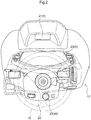
- a panel assembly 17 is provided in a front part of the interior of the cabin part 15, and a steering wheel 16 serving as a maneuvering tool is disposed adjacent to the rear of the panel assembly 17.
- a recessed area is provided at a central location, in the horizontal direction, in a rear part of the panel assembly 17, and the recessed area is recessed further into the front of the machine body than left and right side parts of the panel assembly 17.
- the steering wheel 16 is supported by a steering post 22 that serves as a support member, and a front part of the steering post 22 with respect to the machine body is located in the recessed area. During manual travel, maneuvering operations of the front wheels 11 are performed by a human operating the steering wheel 16.
- maneuver operations includes changing the direction of the machine body 1 by changing the direction of the front wheels 11, but if the travel apparatus is a crawler type, changing the direction of the machine body 1 using a speed difference between left and right crawlers is included in the "maneuvering operations”.
- a meter panel 20 and a side panel 21 are arranged vertically in the panel assembly 17, and the side panel 21 is disposed higher than the meter panel 20.
- the meter panel 20 and the side panel 21 are configured as part of a display unit 4 in terms of a configuration for the automatic maneuvering control.
- a dial switch 23 is disposed on an upper surface of the steering post 22.
- the side panel 21 can be operated by using the dial switch 23 as an operating tool, and the dial switch 23 is disposed in an upper part of the steering post 22 and directly below the steering wheel 16.
- the dial switch 23 is configured to be freely rotatable about an axis extending in the up-down direction (or a direction inclined rearward in a front-back direction of the machine body), and an occupant can switch items of the guidance information displayed in the side panel 21 by rotating the dial switch 23. Additionally, the dial switch 23 can be pressed in a downward direction (or a direction inclined forward in the front-back direction of the machine body).
- This dial switch 23 is also used as a trigger switch 49, which will be described later on the basis of FIG. 3 and the like, and is operated as the trigger switch 49 by the occupant pressing the dial switch 23.
- the dial switch 23 will be called the "trigger switch 49" hereinafter.
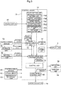
- a control device 75 constituted by a large number of electronic control units (called "ECUs") is provided in the machine body 1.
- the control device 75 is configured to be capable of switching a control mode to an automatic maneuvering mode in which automatic maneuvering control is executed, and a manual maneuvering mode in which automatic maneuvering control is not executed.
- the machine body 1 is provided with a satellite positioning unit 8a, which measures the position of the machine body 1 using GPS (Global Positioning System), which is a well-known technology, as an example of a satellite positioning system (GNSS, or Global Navigation Satellite System) which detects the position of the machine body 1 by receiving radio waves from a satellite.
- GPS Global Positioning System
- GNSS Global Navigation Satellite System
- the satellite positioning unit 8a uses DGPS (Differential GPS, a relative positioning method) in the present embodiment, it is also possible to use RTK-GPS (Real-Time Kinematic GPS, an interference-based positioning method).
- the satellite positioning unit 8a which partially constitutes a position detection unit 8 is provided in the machine body 1, which is the subject of positioning.
- the satellite positioning unit 8a uses an antenna to receive radio waves emitted from a plurality of GPS satellites orbiting the earth.
- the position of the satellite positioning unit 8a is measured on the basis of information in the radio waves received from navigation satellites.
- the machine body 1 is provided with an inertial measurement unit 8b having, for example, an IMU (Inertial Measurement Unit), as a heading detection means that detects a heading of the machine body 1.
- the inertial measurement unit 8b may be configured including a triaxial gyrosensor, a triaxial accelerometer, or the like.
- the inertial measurement unit 8b is provided in a low location at the center of the machine body 1 in a horizontal width direction, for example.
- the inertial measurement unit 8b can detect an angular velocity of a turning angle of the machine body 1, and can calculate a change in the azimuth of the machine body 1 by integrating the angular velocity.
- heading information of the machine body 1 is included in measurement information measured by the inertial measurement unit 8b.
- the inertial measurement unit 8b can also measure an angular velocity of a left-right tilt angle of the machine body 1, a front-back tilt angle of the machine body 1, and the like.
- the control device 75 includes a route setting unit 76, a heading deviation calculation unit 77, a travel trajectory obtainment unit 78, a control unit 79, and a maneuvering control unit 80.
- the route setting unit 76 sets a target travel route LM along which the machine body 1 is to travel (see FIG. 4 , FIG. 8 , and the like).
- the heading deviation calculation unit 77 is configured to be capable of calculating an angular deviation between a travel heading of the machine body 1 and a target heading LA, i.e., a heading deviation.
- the control unit 79 calculates and outputs an operation amount such that the machine body 1 travels along the target travel route LM.
- control unit 79 can calculate and output the operation amount on the basis of the position information of the machine body 1 measured by the satellite positioning unit 8a and the heading information of the machine body 1 measured by the inertial measurement unit 8b.
- the maneuvering control unit 80 controls the steering motor 14 on the basis of the operation amount. Note that the control unit 79 and the maneuvering control unit 80 may be configured in an integrated manner.
- the trigger switch 49 is provided as an operating tool for setting the target travel route LM used in the automatic maneuvering control (see FIG. 4 , FIG. 8 , and the like) and starting the automatic maneuvering control.
- the target travel route LM is set on the basis of the target heading LA (see FIG. 4 ), and the target heading LA is calculated on the basis of a travel trajectory along which the machine body 1 has traveled in the field in advance.
- a start position Ts (see FIG. 4 ) and an end position Tf (see FIG. 4 ) are set by operating the trigger switch 49 in travel performed to obtain the travel trajectory.
- the trigger switch 49 need not be constituted by a single switch, and may instead be configured such that a switch for setting the start position Ts and a switch for setting the end position Tf are arranged side-by-side.
- the vehicle speed sensor 62 is configured to be capable of detecting the vehicle speed from the rotational speed of a transmission shaft in a transmission mechanism for the rear wheels 12. Note that the vehicle speed may be detected not only by the vehicle speed sensor 62, but also using a positioning signal of the satellite positioning unit 8a.
- the obstruction detection unit 63 is provided on both a front part and left and right side parts of the machine body 1, and is configured to be capable of detecting a ridge of the field, metal poles in the field, and so on using an electro-optical rangefinding sensor, an image sensor, or the like, for example.
- an alert is issued to the occupant using an alerting unit 64, which uses a buzzer, audio guidance, or the like, for example.
- the control device 75 is also connected to a reporting unit 59, and the reporting unit 59 is configured to report on states such as the vehicle speed, the engine speed, and the like, for example.
- the reporting unit 59 is configured to be displayed in the display unit 4, for example.
- the alerting unit 64 may be configured to display the alert in the display unit 4 via the reporting unit 59. In this case, an alert that a ridge has been detected, for example, is displayed in the display unit 4.
- the alerting unit 64 may also be configured as part of the reporting unit 59.
- the display unit 4 is configured to be capable of displaying, in a screen, a variety of information based on signal inputs from the reporting unit 59, the alerting unit 64, and the like.
- the display unit 4 is also configured to be capable of displaying various types of guidance information according to conditions of straight travel, conditions of turning travel, and the like of the machine body 1.
- the heading deviation calculation unit 77 calculates an angular deviation between a detected heading of the machine body 1, detected by the satellite positioning unit 8a and the inertial measurement unit 8b, and a target heading LAin the target travel route LM, i.e., calculates the heading deviation. Then, when the control device 75 is set to the automatic maneuvering mode, the control unit 79 calculates and outputs an operation amount for controlling the steering motor 14 so as to reduce the angular deviation. In this manner, the maneuvering control unit 80 is configured to be capable of controlling the maneuvering of the machine body 1 so as to follow the target heading LA.
- the travel trajectory obtainment unit 78 calculates a position of the machine body 1, i.e., a host vehicle position NM, on the basis of the positioning signal measured by the satellite positioning unit 8a, the heading of the machine body 1 calculated by the heading deviation calculation unit 77, and the vehicle speed detected by the vehicle speed sensor 62.
- a storage unit 81 is configured to be capable of storing the host vehicle position NM as position information.
- the travel trajectory obtainment unit 78 stores the host vehicle position NM in the storage unit 81, which is constituted by RAM (Random Access Memory), for example, as time passes.
- the travel trajectory obtainment unit 78 is also configured to be capable of obtaining a travel trajectory on the basis of an aggregation of host vehicle positions NM stored in the storage unit 81.
- the travel trajectory obtainment unit 78 is configured to be capable of obtaining the travel trajectory of the machine body 1 on the basis of the detection, over time, of the host vehicle position NM serving as position information.
- the operation amount is calculated by the control unit 79 on the basis of information on the heading deviation.
- the maneuvering control unit 80 executes the automatic maneuvering control on the basis of the operation amount calculated by the control unit 79 during the automatic maneuvering control of the machine body 1.
- the steering motor 14 is operated such that the detection position of the machine body 1 as detected by the satellite positioning unit 8a and the inertial measurement unit 8b (the host vehicle position NM) is located on the target travel route LM.
- control signal may be the operation amount output by the control unit 79, or may be a voltage value, a current value, or the like with which the maneuvering control unit 80 operates the steering motor 14.
- a reference route setting unit 76A, a target heading calculation unit 76B, and a target travel route setting unit 76C are included in the route setting unit 76.
- a reference route corresponding to a target route for automatic maneuvering is set by the reference route setting unit 76A through reference route setting processing based on operations of the trigger switch 49.
- the target heading calculation unit 76B calculates the target heading LA on the basis of a heading aligned with a lengthwise direction of the reference route.
- the target travel route setting unit 76C is configured to be capable of generating the target travel route LM following the target heading LA, using the reference route and the target heading LA as a reference.
- a start position calculation unit 76D To generate the target travel route LM, a start position calculation unit 76D, an end determination unit 76E, and a distance calculation unit 76F are included in the route setting unit 76.
- the start position calculation unit 76D, the end determination unit 76E, and the distance calculation unit 76F will be described later.
- the reference route setting unit 76A and the target heading calculation unit 76B may be configured in an integrated manner.
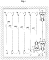
- FIG. 4 schematically illustrates an example of tilling work performed by the tractor.
- work travel in which the tractor moves forward along a linear work route while performing actual tilling work
- turning travel in which the tractor turns to move to the next linear work route
- the first linear work route is a reference route which is steered manually
- the following linear routes are set in sequence by the route setting unit 76 so as to be arranged side-by-side along the reference route.
- These routes correspond to the target travel route LM for automatic maneuvering control, and a plurality of target travel routes LM1 to LM6 are indicated in FIG. 4 .
- Work travel involving automatic maneuvering control is performed in each of the target travel routes LM1 to LM6.
- the machine body 1 moves from an end position Lf of the work travel to a start position Ls of the next work travel in an unworked part of the field while reversing in the opposite direction from the travel direction of the work travel.
- the reference route is generated.
- the occupant manually moves the machine body 1 to a ridge at one corner within the field.
- the occupant operates the trigger switch 49.
- the position at the time when the occupant operates the trigger switch 49 is registered as the start position Ts by the reference route setting unit 76A.
- the occupant performs manual operations to move the machine body 1 straight (or substantially straight) from the start position Ts along the ridge on one side of the field.
- the host vehicle position NM is calculated by the travel trajectory obtainment unit 78 as time passes and is stored in the storage unit 81.
- the position at the time when the occupant operates the trigger switch 49 again is registered as the end position Tf by the reference route setting unit 76A.
- the travel trajectory obtainment unit 78 obtains the travel trajectory on the basis of an aggregate of the host vehicle positions NM between the start position Ts and the end position Tf, and the reference route setting unit 76A calculates the reference route between the start position Ts and the end position Tf on the basis of that travel trajectory.
- the travel of the machine body 1 from the start position Ts to the end position Tf may be work travel involving tilling work, or may be travel in a non-work state.
- automatic maneuvering control can be performed in at least part of the reference route.
- the occupant moves the machine body 1 to the start position Ls in a target region for the first work travel in the field.
- the target region for the first work travel is adjacent to the reference route, and thus the occupant performs turning travel for reversing the travel direction of the machine body 1 by 180 degrees in order to move the machine body 1 to the start position Ls.
- the control unit 79 can determine that the machine body 1 has turned due to the heading of the machine body 1 being reversed.
- the heading of the machine body 1 reversing can be detected by the satellite positioning unit 8a, the inertial measurement unit 8b, or the like.
- the turning of the machine body 1 may be determined by operations of various devices.
- a PTO shaft clutch may be configured to be manipulated in and out.
- the machine body 1 reaching the start position Ls may be determined by the satellite positioning unit 8a.
- the manual maneuvering mode of the control device 75 is continued, and the occupant causes the machine body 1 to travel along the target heading LA through manual operations.
- the control device 75 confirms determination conditions for the heading deviation of the machine body 1 calculated by the heading deviation calculation unit 77, the direction of the front wheels 11, the steering angle of the steering wheel 16, and the like, and determines whether or not the state of the machine body 1 is a state suitable for the next tilling work.
- Whether or not the state of the machine body 1 is suitable for tilling work is determined, for example, using a position distanced from the pre-turning travel position by an integral multiple of a work width in a direction orthogonal to the target heading LA as a reference position, and is determined on the basis of whether or not travel misalignment with respect to the reference position in the left-right direction of the machine body 1 is within a permissible range. If the travel misalignment is outside of the permissible range, the occupant manually steers the machine body 1 so that the travel misalignment of the machine body 1 enters the permissible range.
- the heading deviation of the machine body 1 with respect to the target heading LA being significantly high, the steering wheel 16 being repeatedly steered to the left and right so that the position of the steering wheel 16 fails to stabilize, the vehicle speed of the machine body 1 being too fast or too slow, and so on can be given as examples of states not suitable for tilling work.
- the detection accuracy of the position detection unit 8 being lower than a pre-set threshold can also be given as an example of a state not suitable for tilling work.
- the automatic maneuvering control can be performed by operating the trigger switch 49.
- the target travel route LM1 is set by the target travel route setting unit 76C, and the work travel is started, in response to the occupant operating the trigger switch 49.
- the automatic maneuvering control is performed so that the machine body 1 travels along the target travel route LM1.
- the target travel route LM1 is a target travel route LM which is set to a heading that follows the target heading LA, and in which the machine body 1 performs the first work travel after the setting of the reference route.
- the occupant When the automatic maneuvering control performed along the target travel route LM1 ends, the occupant continues manual steering until, through the above-described turning travel, the state of the machine body 1 becomes a state suitable for the next tilling work. If the trigger switch 49 is permitted to be operated, the occupant operates the trigger switch 49, and the target travel route setting unit 76C sets the target travel route LM2 for the next time to a heading following the target heading LA. Then, the automatic maneuvering control is performed so that the machine body 1 travels along the target travel route LM2. Thereafter, the turning travel, the setting of the target travel route LM, and the work travel are repeated through the above-described process, in order of the target travel routes LM3, LM4, LM5, and LM6.
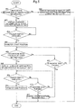
- the reference route setting unit 76A generates the reference route on the basis of the flowchart illustrated in FIG. 5 .
- the route setting unit 76 determines whether or not the position information of the machine body 1 can be detected by the position detection unit 8 (step #01). If the position information of the machine body 1 is not detected (step #01: No), a message indicating that the detection is not possible is displayed in the display unit 4 (step #02), and the reference route is not generated. In this manner, when the accuracy of the obtainment of the position information by the position detection unit 8 is at least a pre-set accuracy, the reference route setting unit 76A can set the start position Ts through an operation of the trigger switch 49, which serves as an operating tool.
- step #03 guidance information for the start position Ts, such as that indicated by 6-Ain FIG. 6 , is displayed in the display unit 4 (step #03), and the start position Ts can be registered.
- the guidance information indicated by 6-A, 6-B, and 6-C in FIG. 6 are displayed in the side panel 21 illustrated in FIG. 2 . Note, however, that the guidance information may be displayed in the meter panel 20 illustrated in FIG. 2 .
- the start position Ts is displayed as "start point A".
- a state where the guidance information for the start position Ts is displayed in the display unit 4 is a standby state for an operation of the trigger switch 49 (step #04).
- the reference route setting unit 76A registers the start position Ts (the start point A) (step #05).
- the reference route setting unit 76A determines whether or not the machine body 1 has traveled at least a pre-set distance by calculating the distance between the start position Ts and the host vehicle positions NM as time passes (step #06). If the travel distance of the machine body 1 has not reached the set distance (step #06: No), guidance information indicating that the travel distance has not reached the set distance is displayed in the display unit 4, even if the occupant operates the trigger switch 49. As the guidance information indicating that the travel distance has not reached the set distance, for example, a message reading "insufficient forward travel distance" is displayed, as indicated by 6-B in FIG. 6 .
- the reference route setting unit 76A can, through an operation of the trigger switch 49, set the end position Tf (an end point B) after the start position Ts (the start point A) has been set by the trigger switch 49 being operated as an operating tool and after the machine body 1 has traveled a pre-set distance following the setting of the start position Ts.
- the reference route setting unit 76A determines whether or not the machine body 1 is turning (step #07).
- a change amount in the maneuvering operations based on operation of the steering wheel 16 is detected by the steering angle sensor 60.
- the configuration is such that the turning of the machine body 1 can be determined by detecting that the change amount in the maneuvering operations based on the detection by the steering angle sensor 60 has exceeded a pre-set range.
- the heading deviation calculation unit 77 can calculate a turning heading of the machine body 1 on the basis of a positioning signal from the satellite positioning unit 8a, an inertia signal from the inertial measurement unit 8b, or the like.
- step #07: Yes the registration of the start position Ts is canceled and the generation of the reference route is aborted (step #12).
- guidance information indicating that the generation of the reference route has been aborted e.g., a message reading "a turn has been detected and the generation of the reference route will end. Please generate the reference route again", is displayed in the display unit 4.
- step #06 If the travel distance of the machine body 1 has reached the set distance (step #06: Yes), guidance information for the end position Tf, such as that indicated by 6-C in FIG. 6 , is displayed in the display unit 4 (step #08), and the end position Tf can then be registered.
- the end position Tf In the guidance information for the end position Tf indicated by 6-C in FIG. 6 , the end position Tf is displayed as the "end point B".
- a state where the guidance information for the end position Tf is displayed in the display unit 4 is a standby state for an operation of the trigger switch 49 (step #09). In this manner, when the end position Tf (the end point B) can be set by operating the trigger switch 49 as an operating tool, the display unit 4 displays an indication that the end position Tf can be set.
- the reference route setting unit 76A registers the end position Tf (step #11).
- the reference route is generated, and the target heading LA is calculated, through the foregoing steps.
- the reference route setting unit 76A sets the reference route on the basis of the travel trajectory of the machine body 1.
- the trigger switch 49 serving as the operating tool is configured to be capable of setting both the start position Ts (the start point A) and the end position Tf (the end point B) when setting the reference route.
- the reference route setting unit 76A determines whether or not the machine body 1 is turning through the same method as in step #07 (step #11). When it is determined that the machine body 1 is turning (step #11: Yes), as described above, the registration of the start position Ts is canceled and the generation of the reference route is aborted (step #12), and guidance information indicating that the generation of the reference route has been aborted is displayed in the display unit 4.
- the display of guidance information in turning travel will be described on the basis of FIG. 7 and FIG. 11 .
- guidance information pertaining to the turning travel is displayed in the display unit 4.
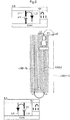
- the guidance information for a left turn, indicated by 8-Ain FIG. 8 and FIG. 9 is displayed in the display unit 4 after automatic travel control along the target travel route LM[n-1] has been performed.
- the guidance information for a right turn, indicated by 8-B in FIG. 8 and FIG. 9 is displayed in the display unit 4 after automatic travel control along the target travel route LM[n] has been performed.
- a map screen showing the machine body 1 and the surroundings of the machine body 1 is included in this guidance information.
- this guidance information is displayed in the side panel 21 illustrated in FIG. 2 , the guidance information may be displayed in the meter panel 20 illustrated in the same drawing.
- FIG. 7 illustrates a flowchart pertaining to the display of the guidance information pertaining to the turning travel, and processing based on this flowchart is performed by the control device 75.
- the end determination unit 76E determines whether or not the automatic maneuvering control for traveling along the target travel route LM has ended (step #21).
- the end of the automatic maneuvering control is determined, for example, on the basis of whether or not a PTO clutch lever (not shown), a pumper lever (not shown), or the like has been operated.
- the end determination unit 76E determines that the automatic maneuvering control has ended (step #21: Yes)
- the host vehicle position NM at the point in time of the determination that the automatic maneuvering control has ended is stored in the storage unit 81 as the end position Lf (step #22).
- the end position Lf is used as work travel position information WP through which the start position calculation unit 76D calculates the start position Ls2 of the next work travel.
- the end position Lf of the target travel route LM[n] is also indicated as the work travel position information WP for calculating the start position Ls2 of the next work travel.
- the present specification assumes that the start position Ls2 will be calculated thereafter by the start position calculation unit 76D, and is therefore described as being distinct from the start position Ls.
- the start position calculation unit 76D is configured to be capable of determining whether the previous turning travel was a right turn or a left turn by reading out data pertaining to the turning travel from the storage unit 81. As illustrated in FIG. 4 , when the machine body 1 repeats the automatic maneuvering control along the target heading LA, the turning travel at the ridges of the field typically alternates between a right turn and a left turn. As such, the start position calculation unit 76D determines whether the previous turning travel was a right turn or a left turn (step #23). Note that the configuration may be such that the determination in step #23 is performed by a module aside from the start position calculation unit 76D.
- the start position calculation unit 76D calculates the next start position Ls2 on a left turn side on the basis of the previous turning travel, before the machine body 1 starts the turn (step #25-1). Guidance information for a left turn is then displayed in the display unit 4 (step #25-2), and a display line L2 based on the start position Ls2 is also displayed in the guidance information.
- the start position calculation unit 76D calculates the next start position Ls2 on a right turn side on the basis of the previous turning travel, before the machine body 1 starts the turn (step #24-1).
- Guidance information for a right turn is then displayed in the display unit 4 (step #24-2), and a display line L2 based on the start position Ls2 is also displayed in the guidance information.
- the start position calculation unit 76D calculates the start position Ls2 on the right or the left of the travel direction of the machine body 1 in the work travel on the basis of the work travel position information WP serving as position information, and the display unit 4 displays guidance information for guiding the turning travel to the start position Ls2.
- the start position calculation unit 76D calculates the start position Ls2 in the other of the left- or right-side turn directions relative to the travel direction in the current turning travel, and the display unit 4 displays the display line L2, based on the start position Ls2, further on the other of the left and right sides than the machine body 1 in the map screen.
- the occupant turns the machine body 1 by operating the steering wheel 16.
- the control device 75 is configured so that the turn direction at this time can be determined by the steering angle sensor 60 serving as a maneuvering operation detection means (step #24-3, step#25-3).
- the means for determining the turn direction is not limited to a determination made by the steering angle sensor 60, and may be, for example, a determination based on an aggregation of the position information of the machine body 1 measured by the satellite positioning unit 8a, a determination based on the heading information of the machine body 1 measured by the inertial measurement unit 8b, or the like.
- the maneuvering operation detection means may be a configuration in which the maneuvering operations is detected by, for example, the satellite positioning unit 8a or the inertial measurement unit 8b detecting a turn.
- the guidance information displayed in the display unit 4 is changed to guidance information which corresponds to the actual turn direction of the machine body 1.
- the start position calculation unit 76D calculates the next start position Ls2 on the left turn side (step #24-4). Then, the guidance information in the display unit 4 is changed to guidance information for a left turn (step #24-5).
- step#25-3 right turn
- step #25-5 the start position calculation unit 76D calculates the next start position Ls2 on the right turn side. Then, the guidance information in the display unit 4 is changed to guidance information for a right turn (step #25-5).
- the start position calculation unit 76D re-calculates the start position Ls2 in the turn direction on the side toward which the steering wheel 16 has been operated, and the display unit 4 re-displays the start position Ls2 in the map screen, further than the machine body 1 toward the side corresponding to the turn direction in which the steering wheel 16 has been operated.
- step #26 Before describing step #26 and on, a method by which the start position calculation unit 76D calculates the start position Ls2 will be described.
- the host vehicle position NM at the point in time when the end of the automatic maneuvering control was determined is stored in the storage unit 81 as the end position Lf of the target travel route LM[n] (the work travel position information WP) on the basis of step #22 in FIG. 7 .
- a left turn is made from the end position Lf of the target travel route LM[n-1] to the start position Ls of the target travel route LM[n]. Accordingly, a right turn is determined in step #23 of FIG. 7 before the machine body 1 turns from the end position Lf of the target travel route LM[n], i.e., the work travel position information WP.
- the end position Lf of the target travel route LM[n-1] and the start position Ls of the target travel route LM[n] are separated by a first separation distance P1.
- An area of work travel based on the target travel route LM[n-1] and an area of work travel based on the target travel route LM[n] are areas which are adjacent to each other.
- the first separation distance P1 is a distance equivalent to the work width of the tilling device 3 attached to the tractor via a PTO shaft, or a distance around ten percent smaller than the work width of the tilling device 3, for example.
- the first separation distance P1 is as described on the basis of FIG. 8 .
- the work width of the work travel based on the target travel route LM[n-1] and the work width of the work travel based on the target travel route LM[n] overlap by a predetermined width (less than ten percent of the work width, for example).
- the end position Lf of the target travel route LM[n-1] is a position where the previous turning travel was started.
- the start position Ls of the target travel route LM[n] is a position where the previous turning travel ended. Furthermore, the end position Lf of the target travel route LM[n-1] and the start position Ls of the target travel route LM[n] are separated by the first separation distance P1. Based on this, the start position calculation unit 76D estimates that the next automatic maneuvering control will be performed at a position separated from the target travel route LM[n] in the horizontal direction (a direction orthogonal to the target heading LA; the same applies hereinafter) by the first separation distance P1.
- the start position calculation unit 76D then calculates the start position Ls2 for new work travel on a side opposite to where the target travel route LM[n-1] is located, in the horizontal direction, with respect to the work travel position information WP, the start position Ls2 for new work travel being separated from the work travel position information WP by the first separation distance P1 (step #25-1).
- a target travel route LM[n+1] illustrated in FIG. 8 is a planned target travel route LM set after the machine body 1 has reached the start position Ls2.
- step #25-2 guidance information for the right turn indicated by 8-B in FIG. 8 is displayed in the display unit 4 as the map screen.
- the display unit 4 displays the surroundings of the machine body 1, including the machine body 1, as the map screen.
- the work travel position information WP and the start position Ls2 of the next work travel are displayed in this map screen as linear display lines L1 and L2, respectively, which follow the target heading LA.
- the start position calculation unit 76D calculates the start position Ls2 on the basis of the separation distance between the position where the previous turning travel started and the position where the previous turning travel ended, and the display unit 4 displays the start position Ls2, calculated on the basis of the separation distance, in the guidance information.
- a machine body symbol SY and a turning route indicated by a broken line are schematically indicated in the map screen in the guidance information displayed in the display unit 4. While the machine body 1 is performing turning travel, the machine body symbol SY indicating the position of the machine body 1 moves along the turning route indicated by the broken line, as indicated in the guidance information for 8-B and 8-C in FIG. 9 .
- the display unit 4 displays the turning route of the turning travel in the map screen, the turning route is not set in advance in the present embodiment, and the turning route indicated by the broken line is displayed in the map screen as a guide for reaching the start position Ls2.
- the machine body symbol SY is displayed as a guide in any desired location on the turning route indicated by the broken line, on the basis of the host vehicle position NM calculated by the travel trajectory obtainment unit 78. Additionally, the orientation of the machine body symbol SY changes in the map screen in the guidance information on the basis of a turning heading calculated by the heading deviation calculation unit 77 (see FIG. 3 ).
- the distance calculation unit 76F (see FIG. 3 ) is configured to be capable of calculating the separation distance between the position information stored in the storage unit 81 and the position information based on the current position of the machine body 1. While the machine body 1 is performing turning travel, the separation distance between the work travel position information WP and the host vehicle position NM is calculated by the distance calculation unit 76F as time passes (step #26). In other words, the distance calculation unit 76F calculates the separation distance using the position information from the point in time when the end determination unit 76E (see FIG. 3 ) determines that the work travel has ended. The distance calculation unit 76F starts calculating the separation distance after the turning travel has started.
- a separation distance display DF which is a distance of a component of the separation distance which is orthogonal to the target heading LA, is displayed in the display unit 4 (step #27).
- the distance calculation unit 76F calculates the separation distance using, as the position information stored in the storage unit 81, the work travel position information WP, which is position information based on the work travel determined by the end determination unit 76E to have ended.
- the display unit 4 is configured to be capable of displaying the work travel position information WP and the separation distance display DF. The display unit 4 starts displaying the separation distance after the turning travel has started.
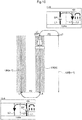
- FIG. 9 illustrates a state in which, in the turning travel, the machine body 1 travels a distance greater than the first separation distance P1 from the work travel position information WP in the horizontal direction, and passes the start position Ls2 of the next work travel (indicated as a planned start position Ls2' in FIG. 9 ). Although the planned start position Ls2' indicated in FIG.
- step #28 of FIG. 7 the start position calculation unit 76D calculates the start position Ls2 of a new work travel at a position separated from the planned start position Ls2' by the first separation distance P1 in the horizontal direction, on the side opposite from the side of the location of the work travel position information WP (step #29).
- a target travel route LM[n+2] illustrated in FIG. 9 is a planned target travel route LM set after the machine body 1 has reached the start position Ls2.
- a second separation distance P2 which is a separation distance between the work travel position information WP and the start position Ls2 of the new work travel, is indicated in FIG. 9 .
- the second separation distance P2 is double the distance of the first separation distance P1.
- an unworked part having a width equivalent to the work width of the tilling device 3 in the horizontal direction remains between the area of the work travel based on the target travel route LM[n] and the area of the work travel to be performed on the basis of the start position Ls2 of the new work travel.
- the width of the unworked part is a width over which tilling work can be performed between already-worked parts on both sides, without gaps, when performing the tilling work.
- the second separation distance P2 is as described on the basis of FIG. 9 .
- the guidance information for a right turn, indicated by 8-C in FIG. 9 is displayed in the display unit 4 as a map screen, on the basis of the process of step #30.
- the work travel position information WP, the planned start position Ls2', and the start position Ls2 of the new work travel are displayed in the map screen indicated by 8-C as linear display lines L1, L2', and L2, respectively, which follow the target heading LA.
- the display line L2' based on the planned start position Ls2' is located between the display line L1 based on the work travel position information WP and the display line L2' based on the start position Ls2 of the new work travel.
- a turning route indicated by a broken line is displayed from the display line L1 based on the work travel position information WP to the display line L2' based on the start position Ls2 of the new work travel, as a guide for reaching the start position Ls2 of the new work travel.
- the display of the machine body symbol SY and the display of the separation distance display DF in the guidance information indicated by 8-C in FIG. 9 are as already described on the basis of the guidance information indicated by 8-B in the same drawing.
- step #31 While the machine body 1 is performing turning travel, it is determined whether or not the heading deviation, calculated by the heading deviation calculation unit 77 (see FIG. 3 ), between the turning heading of the machine body 1 and the target heading LA is within a pre-set permissible range (step #31). If the heading deviation is outside the permissible range (step #31: No), the determination process of step #28, and the processes of step #29 and step #30 performed when a determination of Yes is made in step #28, are repeated. When the heading deviation is within the permissible range (step #31: Yes), the distance between the work travel position information WP and the start position Ls2 of the next work travel is stored in the storage unit 81 (see FIG. 3 ) (step #32), and the processing moves to the flowchart illustrated in FIG. 12 , which will be described later. Additionally, after the turning travel has ended, the display unit 4 ends the display of the separation distance display DF.
- step #31 whether or not a distance, in the horizontal direction, between the work travel position information WP and the host vehicle positions NM calculated by the travel trajectory obtainment unit 78 is within the range of a reference distance that takes the work width of the work travel as a reference may be added as a determination item.
- a value which is an integral multiple of the work width may be used as the reference distance, or a value obtained by subtracting the aforementioned overlap amount from the value which is an integral multiple of the work width may be used as the reference distance.
- the distance recorded in the storage unit 81 in step #32 may be the actual distance between the work travel position information WP and the start position Ls2 of the next work travel, or may be a distance, among distances which are integral multiples of the reference distance which takes the work width of the work travel as a reference, that is close to the actual distance.
- the distance stored in the storage unit 81 is, for example, the first separation distance P1, the second separation distance P2, or the like.
- FIG. 10 before the automatic maneuvering control in the target travel route LM[n], a left turn is made across the end position Lf of the target travel route LM[n-1] and the start position Ls of the target travel route LM[n].
- the guidance information for a left turn is displayed in the display unit 4 after automatic travel control along the target travel route LM[n-1] has been performed.
- the guidance information for a right turn is displayed in the display unit 4 on the basis of the process of step #24-2 indicated in FIG. 7 , after the automatic travel control has been performed along the target travel route LM[n] and before the machine body 1 actually starts the turn.
- a map screen showing the machine body 1 and the surroundings of the machine body 1 is included in this guidance information. Additionally, although this guidance information is displayed in the side panel 21 illustrated in FIG. 2 , the guidance information may be displayed in the meter panel 20 illustrated in the same drawing.
- the end position Lf of the target travel route LM[n-1] and the start position Ls of the target travel route LM[n] are separated by the second separation distance P2, and the second separation distance P2 has a distance of double (or substantially double but less than double) the work width of the tilling device 3.
- the second separation distance P2 has a distance of double (or substantially double but less than double) the work width of the tilling device 3.
- the start position calculation unit 76D estimates that the next automatic maneuvering control will be performed at a position separated from the target travel route LM[n] in the horizontal direction by the second separation distance P2.
- the start position calculation unit 76D then calculates the start position Ls2 for the next work travel at a position which is in the horizontal direction to the side opposite from the side on which the target travel route LM[n-1] is located, and which is separated from the work travel position information WP by the second separation distance P2.
- the target travel route LM[n+1] illustrated in FIG. 10 is a planned target travel route LM set after the machine body 1 has reached the start position Ls2.
- the display line L1 based on the work travel position information WP and the display line L2' based on the start position Ls2 of the next work travel are displayed in the guidance information indicated by 10-B in FIG. 10 and FIG. 11 .
- an unworked part having a width equivalent to the work width of the tilling device 3 in the horizontal direction remains between the work travel position information WP and the start position Ls2 of the next work travel.
- a display line L3 indicating the unworked part is displayed between the display line L1 based on the work travel position information WP and the display line L2 based on the start position Ls2 of the next work travel.
- the width of the unworked part is a width over which tilling work can be performed between already-worked parts on both sides, without gaps, when performing the tilling work.
- the guidance information for a right turn is displayed in the display unit 4 on the basis of the process of step #24-2 indicated in FIG. 7 , after the automatic travel control has been performed along the target travel route LM[n] and before the machine body 1 actually starts the turn.
- the target travel route LM[n] is approaching a ridge, on one side of the field, that follows the target heading LA, it is conceivable that the machine body 1 cannot actually turn any further to the right from the work travel position information WP. If the machine body 1 has actually turned to the left as indicated in FIG. 11 , a left turn is determined in step #24-3 of FIG.
- the start position Ls2 indicated in FIG. 10 is indicated as the planned start position Ls2' in FIG. 11 , and the planned start position Ls2' is not used as the start position Ls2 for generating the next target travel route LM.
- step #24-4 indicated in FIG. 7 the start position calculation unit 76D calculates the start position Ls2 for generating the next target travel route LM on the basis of the previous turning travel.
- the start position calculation unit 76D calculates the start position Ls2 for generating the next target travel route LM at a position separated from the work travel position information WP by the second separation distance P2.
- the area of the work travel based on the target travel route LM[n-1] has already undergone work travel.
- the width of this unworked part in the horizontal direction is equivalent to the work width of the tilling device 3.
- the start position calculation unit 76D calculates the start position Ls2 for generating the next target travel route LM at a position separated from the work travel position information WP by the first separation distance P1.
- the target travel route LM[n+2] illustrated in FIG. 11 is a planned target travel route LM set after the machine body 1 has reached the start position Ls2.
- the manual maneuvering mode of the control device 75 is continued, and straight travel is continued on the basis of human operation.
- the control device 75 confirms the determination conditions for heading deviation of the machine body 1 relative to the target heading LA, the direction of the front wheels 11, and the steering state of the steering wheel 16, and determines whether or not the state is one in which the mode can switch to the automatic maneuvering mode. Then, if the state is one in which the control device 75 can switch to the automatic maneuvering mode, the automatic maneuvering control is started in response to the occupant operating the trigger switch 49.
- the occupant can, using the display unit 4, visually confirm whether or not the state is one in which the control device 75 can switch to the automatic maneuvering mode.
- guidance information that assists the occupant in making the maneuvering operations is displayed in the display unit 4.
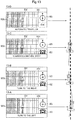
- a screen for the guidance information indicated by 13-A to 13-D in FIG. 13 is displayed in the display unit 4.
- a map screen showing the machine body 1 and the surroundings of the machine body 1 is included in this guidance information.
- This guidance information is displayed in the side panel 21 illustrated in FIG. 2 , but may be displayed in the meter panel 20 displayed in the same drawing.
- a steering display 82 of the steering wheel 16, and a heading deviation display 83 of the machine body 1 calculated by the heading deviation calculation unit 77 are displayed in a vertical arrangement at the right end of the guidance information screen.
- a map screen including the machine body symbol SY is displayed in the screen to the left of the steering display 82 and the heading deviation display 83, and in this map screen, already-worked parts, for which the tilling work is already complete, are indicated by a color indication WA.
- the color indication WA is calculated from the aggregation of the host vehicle positions NM stored in the storage unit 81 and the work width of the tilling device 3. This makes a clear visual distinction between already-worked parts and unworked parts.
- the configuration may be such that of the areas in which the color indication WAis displayed, areas that have undergone work travel three or more times, areas that have undergone work travel twice, and areas that have only undergone work travel once are distinguished by different colors.
- the configuration may be such that the color indication WA is a different color depending on the number of times work travel has been performed, and the already-worked parts in the guidance information are displayed using color indications WA of different colors.
- the color indication WA may instead be point-based indications or pattern-based indications.
- the determination to start the automatic maneuvering control is made on the basis of the flowchart illustrated in FIG. 12 .
- the control device 75 is configured to use a determination counter Ctr to determine whether or not the state is one in which the control device 75 can switch to the automatic maneuvering mode.
- the value of the counter Ctr immediately after the turning travel has ended is set to zero (step #40).
- step #43-2 Information prompting the occupant to turn the steering wheel 16 to the left is displayed in the guidance information for a left turn indicated by 13-A in FIG. 13 . If the heading of the machine body 1 is slanted to the left relative to the target heading LA (step #41: left slant), guidance information for a right turn, indicated by 13-B in FIG. 13 , is displayed in the display unit 4 (step #42-1). The value of the counter Ctr is then reset to zero (step #42-2). Information prompting the occupant to turn the steering wheel 16 to the right is displayed in the guidance information for a right turn indicated by 13-B in FIG. 13 .
- step #45 While the machine body 1 is traveling straight in a direction following the target heading LA (step #41: straight), the counter Ctr is incremented (step #44), and the value of the counter Ctr increases. It is then determined whether or not the machine body 1 has traveled at least a set distance (step #45).
- the "set distance” may be a pre-set distance from the start position Ls2 (see FIG. 8 to FIG. 11 ), or may be a pre-set distance from a state in which the machine body 1 travels straight in a direction following the target heading LA. If the machine body 1 has not traveled at least the set distance (step #45: No), the processing returns to step #41.
- step #46 it is determined whether a change in the turning angle of the steering wheel 16 remains within a permissible range.
- a state in which the steering wheel 16 is moved neither in the direction of a right turn nor in the direction of a left turn, and the directions of the front wheels 11 and the rear wheels 12 are parallel, can be given as an example of a turning angle of the steering wheel 16 for when automatic maneuvering control is permitted, but the state is not limited thereto.
- the travel area of the machine body 1 is a ground surface that slopes in the horizontal direction, there is a risk that if the machine body 1 simply continues traveling straight, the machine body 1 will gradually shift toward the lower ground in the left-right direction.
- the turning angle of the steering wheel 16 when the automatic maneuvering control is permitted also includes states in which the steering wheel 16 is steered in the directions of a right turn or a left turn, for example.
- the control device 75 is configured so that the automatic maneuvering control is permitted when the turning angle of the steering wheel 16 continues to be kept within a set range. If the change in the turning angle of the steering wheel 16 is not kept within the permissible range (step #46: No), the counter Ctr is reset to zero (step #47). Note that the configuration may be such that in the process of step #47, the value of the counter Ctr may be decremented to reduce the value of the counter Ctr rather than resetting the value of the counter Ctr to zero.
- the guidance information indicated by 13-C in FIG. 13 is displayed in the display unit 4 from when the straight travel is determined in step #41 to when the determination of step #46 is made. Then, when the counter Ctr has reached a pre-set value (step #48: Yes), the guidance information indicated by 13-D in FIG. 13 is displayed in the display unit 4, and the automatic maneuvering control is permitted. Then, the control mode of the control device 75 is switched from the manual maneuvering mode to the automatic maneuvering mode in response to the occupant operating the trigger switch 49, and the automatic maneuvering control is executed (step #49).
- the configuration may be such that if a sharp turn of the steering wheel 16 is detected after a determination of Yes is made in step #48 but before the occupant operates the trigger switch 49, the value of the counter Ctr is reset to zero, decremented, or the like.
- the present invention can be applied in traveling work machines in which a target heading can be calculated on the basis of a travel trajectory and maneuvering of a machine body can be controlled to follow the target heading.
Landscapes
- Engineering & Computer Science (AREA)
- Radar, Positioning & Navigation (AREA)
- Remote Sensing (AREA)
- Mechanical Engineering (AREA)
- General Physics & Mathematics (AREA)
- Automation & Control Theory (AREA)
- Physics & Mathematics (AREA)
- Life Sciences & Earth Sciences (AREA)
- Aviation & Aerospace Engineering (AREA)
- Chemical & Material Sciences (AREA)
- Combustion & Propulsion (AREA)
- Transportation (AREA)
- Environmental Sciences (AREA)
- Soil Sciences (AREA)
- Business, Economics & Management (AREA)
- Health & Medical Sciences (AREA)
- Artificial Intelligence (AREA)
- Evolutionary Computation (AREA)
- Game Theory and Decision Science (AREA)
- Medical Informatics (AREA)
- Guiding Agricultural Machines (AREA)
Applications Claiming Priority (3)
| Application Number | Priority Date | Filing Date | Title |
|---|---|---|---|
| JP2018238892A JP7045979B2 (ja) | 2018-12-20 | 2018-12-20 | 走行作業機 |
| JP2018238896A JP7122956B2 (ja) | 2018-12-20 | 2018-12-20 | 走行作業機 |
| PCT/JP2019/047816 WO2020129704A1 (fr) | 2018-12-20 | 2019-12-06 | Machine de travail à déplacement |
Publications (3)
| Publication Number | Publication Date |
|---|---|
| EP3900507A1 true EP3900507A1 (fr) | 2021-10-27 |
| EP3900507A4 EP3900507A4 (fr) | 2022-12-21 |
| EP3900507B1 EP3900507B1 (fr) | 2024-10-16 |
Family
ID=71101723
Family Applications (1)
| Application Number | Title | Priority Date | Filing Date |
|---|---|---|---|
| EP19898663.0A Active EP3900507B1 (fr) | 2018-12-20 | 2019-12-06 | Machine de travail à déplacement |
Country Status (3)
| Country | Link |
|---|---|
| US (1) | US11809188B2 (fr) |
| EP (1) | EP3900507B1 (fr) |
| WO (1) | WO2020129704A1 (fr) |
Cited By (2)
| Publication number | Priority date | Publication date | Assignee | Title |
|---|---|---|---|---|
| EP4205521A1 (fr) * | 2021-12-28 | 2023-07-05 | Kubota Corporation | Système d'assistance agricole, machine agricole et appareil d'assistance agricole |
| FI20245475A1 (fi) * | 2024-04-15 | 2025-10-16 | Ponsse Oyj | Menetelmä metsätyökoneen ohjaamiseksi ja metsätyökone |
Families Citing this family (12)
| Publication number | Priority date | Publication date | Assignee | Title |
|---|---|---|---|---|
| JP7791751B2 (ja) * | 2022-03-22 | 2025-12-24 | 三菱マヒンドラ農機株式会社 | 作業車両 |
| JP7706413B2 (ja) | 2022-04-13 | 2025-07-11 | 株式会社クボタ | 圃場作業車両 |
| JP7851829B2 (ja) * | 2022-09-12 | 2026-04-27 | ヤンマーホールディングス株式会社 | 経路生成方法、経路生成システム、及び経路生成プログラム |
| JP2024110440A (ja) * | 2023-02-03 | 2024-08-16 | ヤンマーホールディングス株式会社 | 経路生成方法、経路生成システム、及び経路生成プログラム |
| USD1062768S1 (en) * | 2023-03-13 | 2025-02-18 | Deere & Company | Display screen or portion thereof with icon |
| USD1062767S1 (en) * | 2023-03-13 | 2025-02-18 | Deere & Company | Display screen or portion thereof with graphical user interface |
| USD1063980S1 (en) * | 2023-03-13 | 2025-02-25 | Deere & Company | Display screen or portion thereof with transitional graphical user interface |
| USD1063961S1 (en) * | 2023-03-13 | 2025-02-25 | Deere & Company | Display screen or portion thereof with transitional icon |
| USD1062779S1 (en) * | 2023-03-13 | 2025-02-18 | Deere & Company | Display screen or portion thereof with icon |
| USD1063960S1 (en) * | 2023-03-13 | 2025-02-25 | Deere & Company | Display screen or portion thereof with graphical user interface |
| JP2025070051A (ja) * | 2023-10-19 | 2025-05-02 | ヤンマーホールディングス株式会社 | 作業車両の制御方法、作業車両用制御プログラム、作業車両用制御システム及び作業システム |
| US20250130049A1 (en) * | 2023-10-19 | 2025-04-24 | Yanmar Holdings Co., Ltd. | Control method of work vehicle, control program for work vehicle, control system for work vehicle, and work system |
Family Cites Families (10)
| Publication number | Priority date | Publication date | Assignee | Title |
|---|---|---|---|---|
| JP2012120481A (ja) | 2010-12-08 | 2012-06-28 | Iseki & Co Ltd | 防除作業機 |
| JP2015112056A (ja) | 2013-12-11 | 2015-06-22 | 井関農機株式会社 | 農用作業車両 |
| CA2923683C (fr) * | 2013-12-12 | 2018-03-13 | Hitachi Construction Machinery Co., Ltd. | Systeme de deplacement de vehicule et procede de commande de deplacement de vehicule |
| KR20210082559A (ko) * | 2014-02-06 | 2021-07-05 | 얀마 파워 테크놀로지 가부시키가이샤 | 병주 작업 시스템 |
| JP2016007196A (ja) * | 2014-06-26 | 2016-01-18 | 株式会社クボタ | 植播系水田作業機 |
| KR102698059B1 (ko) * | 2016-03-09 | 2024-08-22 | 얀마 파워 테크놀로지 가부시키가이샤 | 작업 차량 및 주행 영역 특정 장치 |
| JP6945279B2 (ja) * | 2016-06-28 | 2021-10-06 | 株式会社クボタ | 作業車 |
| JP6698007B2 (ja) | 2016-12-20 | 2020-05-27 | 株式会社クボタ | 自動走行作業車 |
| JP6673862B2 (ja) * | 2017-03-03 | 2020-03-25 | ヤンマー株式会社 | 走行経路特定システム |
| JP6811655B2 (ja) | 2017-03-14 | 2021-01-13 | 株式会社クボタ | 作業車 |
-
2019
- 2019-12-06 WO PCT/JP2019/047816 patent/WO2020129704A1/fr not_active Ceased
- 2019-12-06 US US17/295,902 patent/US11809188B2/en active Active
- 2019-12-06 EP EP19898663.0A patent/EP3900507B1/fr active Active
Cited By (3)
| Publication number | Priority date | Publication date | Assignee | Title |
|---|---|---|---|---|
| EP4205521A1 (fr) * | 2021-12-28 | 2023-07-05 | Kubota Corporation | Système d'assistance agricole, machine agricole et appareil d'assistance agricole |
| US12433183B2 (en) | 2021-12-28 | 2025-10-07 | Kubota Corporation | Agricultural assistance system, agricultural machine, and agricultural assistance apparatus |
| FI20245475A1 (fi) * | 2024-04-15 | 2025-10-16 | Ponsse Oyj | Menetelmä metsätyökoneen ohjaamiseksi ja metsätyökone |
Also Published As
| Publication number | Publication date |
|---|---|
| US20210397190A1 (en) | 2021-12-23 |
| US11809188B2 (en) | 2023-11-07 |
| EP3900507A4 (fr) | 2022-12-21 |
| WO2020129704A1 (fr) | 2020-06-25 |
| EP3900507B1 (fr) | 2024-10-16 |
Similar Documents
| Publication | Publication Date | Title |
|---|---|---|
| EP3900507B1 (fr) | Machine de travail à déplacement | |
| EP3900510B1 (fr) | Machine de travail en déplacement | |
| JP2024164121A5 (fr) | ||
| AU2017318897B2 (en) | Image display system for work machine | |
| EP3351077B1 (fr) | Dispositif de génération d'itinéraire et programme de génération d'itinéraire | |
| EP3336794B1 (fr) | Appareil et procédé de génération d'une voie de voyage pour un véhicule agricole | |
| KR101879247B1 (ko) | 자율주행 농업기계의 작업경로 설정방법 | |
| JP6727944B2 (ja) | 圃場走行経路生成システム及び圃場作業車 | |
| EP3272586A1 (fr) | Véhicule de travail | |
| CN114080579A (zh) | 自动行驶系统 | |
| EP3932159B1 (fr) | Système de déplacement autonome | |
| KR102534336B1 (ko) | 경로 생성 시스템 | |
| JP7080101B2 (ja) | 作業車 | |
| JP2016189172A (ja) | 自動走行情報管理システム | |
| JP7045979B2 (ja) | 走行作業機 | |
| JP7122956B2 (ja) | 走行作業機 | |
| EP4275466B1 (fr) | Système de trajet automatique et procédé de trajet automatique | |
| JP2016189171A (ja) | 自動走行情報管理システム | |
| EP4613082A1 (fr) | Véhicule de travail |
Legal Events
| Date | Code | Title | Description |
|---|---|---|---|
| STAA | Information on the status of an ep patent application or granted ep patent |
Free format text: STATUS: THE INTERNATIONAL PUBLICATION HAS BEEN MADE |
|
| PUAI | Public reference made under article 153(3) epc to a published international application that has entered the european phase |
Free format text: ORIGINAL CODE: 0009012 |
|
| STAA | Information on the status of an ep patent application or granted ep patent |
Free format text: STATUS: REQUEST FOR EXAMINATION WAS MADE |
|
| 17P | Request for examination filed |
Effective date: 20210527 |
|
| AK | Designated contracting states |
Kind code of ref document: A1 Designated state(s): AL AT BE BG CH CY CZ DE DK EE ES FI FR GB GR HR HU IE IS IT LI LT LU LV MC MK MT NL NO PL PT RO RS SE SI SK SM TR |
|
| DAV | Request for validation of the european patent (deleted) | ||
| DAX | Request for extension of the european patent (deleted) | ||
| RIC1 | Information provided on ipc code assigned before grant |
Ipc: G05D 1/02 20200101ALI20220816BHEP Ipc: G01C 21/20 20060101ALI20220816BHEP Ipc: A01B 69/04 20060101AFI20220816BHEP |
|
| A4 | Supplementary search report drawn up and despatched |
Effective date: 20221123 |
|
| RIC1 | Information provided on ipc code assigned before grant |
Ipc: G05D 1/02 20200101ALI20221117BHEP Ipc: G01C 21/20 20060101ALI20221117BHEP Ipc: A01B 69/04 20060101AFI20221117BHEP |
|
| REG | Reference to a national code |
Ref country code: DE Ref legal event code: R079 Free format text: PREVIOUS MAIN CLASS: A01B0069000000 Ipc: A01B0069040000 Ref country code: DE Ref legal event code: R079 Ref document number: 602019060638 Country of ref document: DE Free format text: PREVIOUS MAIN CLASS: A01B0069000000 Ipc: A01B0069040000 |
|
| GRAP | Despatch of communication of intention to grant a patent |
Free format text: ORIGINAL CODE: EPIDOSNIGR1 |
|
| STAA | Information on the status of an ep patent application or granted ep patent |
Free format text: STATUS: GRANT OF PATENT IS INTENDED |
|
| RIC1 | Information provided on ipc code assigned before grant |
Ipc: G01C 21/20 20060101ALI20240419BHEP Ipc: A01B 69/04 20060101AFI20240419BHEP |
|
| INTG | Intention to grant announced |
Effective date: 20240516 |
|
| GRAS | Grant fee paid |
Free format text: ORIGINAL CODE: EPIDOSNIGR3 |
|
| GRAA | (expected) grant |
Free format text: ORIGINAL CODE: 0009210 |
|
| STAA | Information on the status of an ep patent application or granted ep patent |
Free format text: STATUS: THE PATENT HAS BEEN GRANTED |
|
| AK | Designated contracting states |
Kind code of ref document: B1 Designated state(s): AL AT BE BG CH CY CZ DE DK EE ES FI FR GB GR HR HU IE IS IT LI LT LU LV MC MK MT NL NO PL PT RO RS SE SI SK SM TR |
|
| REG | Reference to a national code |
Ref country code: GB Ref legal event code: FG4D |
|
| REG | Reference to a national code |
Ref country code: CH Ref legal event code: EP |
|
| REG | Reference to a national code |
Ref country code: IE Ref legal event code: FG4D |
|
| REG | Reference to a national code |
Ref country code: DE Ref legal event code: R096 Ref document number: 602019060638 Country of ref document: DE |
|
| REG | Reference to a national code |
Ref country code: LT Ref legal event code: MG9D |
|
| REG | Reference to a national code |
Ref country code: NL Ref legal event code: MP Effective date: 20241016 |
|
| REG | Reference to a national code |
Ref country code: AT Ref legal event code: MK05 Ref document number: 1732103 Country of ref document: AT Kind code of ref document: T Effective date: 20241016 |
|
| PG25 | Lapsed in a contracting state [announced via postgrant information from national office to epo] |
Ref country code: NL Free format text: LAPSE BECAUSE OF FAILURE TO SUBMIT A TRANSLATION OF THE DESCRIPTION OR TO PAY THE FEE WITHIN THE PRESCRIBED TIME-LIMIT Effective date: 20241016 |
|
| PG25 | Lapsed in a contracting state [announced via postgrant information from national office to epo] |
Ref country code: NL Free format text: LAPSE BECAUSE OF FAILURE TO SUBMIT A TRANSLATION OF THE DESCRIPTION OR TO PAY THE FEE WITHIN THE PRESCRIBED TIME-LIMIT Effective date: 20241016 |
|
| PG25 | Lapsed in a contracting state [announced via postgrant information from national office to epo] |
Ref country code: PT Free format text: LAPSE BECAUSE OF FAILURE TO SUBMIT A TRANSLATION OF THE DESCRIPTION OR TO PAY THE FEE WITHIN THE PRESCRIBED TIME-LIMIT Effective date: 20250217 Ref country code: HR Free format text: LAPSE BECAUSE OF FAILURE TO SUBMIT A TRANSLATION OF THE DESCRIPTION OR TO PAY THE FEE WITHIN THE PRESCRIBED TIME-LIMIT Effective date: 20241016 Ref country code: IS Free format text: LAPSE BECAUSE OF FAILURE TO SUBMIT A TRANSLATION OF THE DESCRIPTION OR TO PAY THE FEE WITHIN THE PRESCRIBED TIME-LIMIT Effective date: 20250216 |
|
| PG25 | Lapsed in a contracting state [announced via postgrant information from national office to epo] |
Ref country code: FI Free format text: LAPSE BECAUSE OF FAILURE TO SUBMIT A TRANSLATION OF THE DESCRIPTION OR TO PAY THE FEE WITHIN THE PRESCRIBED TIME-LIMIT Effective date: 20241016 |
|
| PG25 | Lapsed in a contracting state [announced via postgrant information from national office to epo] |
Ref country code: BG Free format text: LAPSE BECAUSE OF FAILURE TO SUBMIT A TRANSLATION OF THE DESCRIPTION OR TO PAY THE FEE WITHIN THE PRESCRIBED TIME-LIMIT Effective date: 20241016 |
|
| PG25 | Lapsed in a contracting state [announced via postgrant information from national office to epo] |
Ref country code: ES Free format text: LAPSE BECAUSE OF FAILURE TO SUBMIT A TRANSLATION OF THE DESCRIPTION OR TO PAY THE FEE WITHIN THE PRESCRIBED TIME-LIMIT Effective date: 20241016 |
|
| PG25 | Lapsed in a contracting state [announced via postgrant information from national office to epo] |
Ref country code: NO Free format text: LAPSE BECAUSE OF FAILURE TO SUBMIT A TRANSLATION OF THE DESCRIPTION OR TO PAY THE FEE WITHIN THE PRESCRIBED TIME-LIMIT Effective date: 20250116 |
|
| PG25 | Lapsed in a contracting state [announced via postgrant information from national office to epo] |
Ref country code: LV Free format text: LAPSE BECAUSE OF FAILURE TO SUBMIT A TRANSLATION OF THE DESCRIPTION OR TO PAY THE FEE WITHIN THE PRESCRIBED TIME-LIMIT Effective date: 20241016 Ref country code: GR Free format text: LAPSE BECAUSE OF FAILURE TO SUBMIT A TRANSLATION OF THE DESCRIPTION OR TO PAY THE FEE WITHIN THE PRESCRIBED TIME-LIMIT Effective date: 20250117 Ref country code: AT Free format text: LAPSE BECAUSE OF FAILURE TO SUBMIT A TRANSLATION OF THE DESCRIPTION OR TO PAY THE FEE WITHIN THE PRESCRIBED TIME-LIMIT Effective date: 20241016 |
|
| PG25 | Lapsed in a contracting state [announced via postgrant information from national office to epo] |
Ref country code: PL Free format text: LAPSE BECAUSE OF FAILURE TO SUBMIT A TRANSLATION OF THE DESCRIPTION OR TO PAY THE FEE WITHIN THE PRESCRIBED TIME-LIMIT Effective date: 20241016 |
|
| PG25 | Lapsed in a contracting state [announced via postgrant information from national office to epo] |
Ref country code: RS Free format text: LAPSE BECAUSE OF FAILURE TO SUBMIT A TRANSLATION OF THE DESCRIPTION OR TO PAY THE FEE WITHIN THE PRESCRIBED TIME-LIMIT Effective date: 20250116 |
|
| PG25 | Lapsed in a contracting state [announced via postgrant information from national office to epo] |
Ref country code: SM Free format text: LAPSE BECAUSE OF FAILURE TO SUBMIT A TRANSLATION OF THE DESCRIPTION OR TO PAY THE FEE WITHIN THE PRESCRIBED TIME-LIMIT Effective date: 20241016 |
|
| PG25 | Lapsed in a contracting state [announced via postgrant information from national office to epo] |
Ref country code: MC Free format text: LAPSE BECAUSE OF FAILURE TO SUBMIT A TRANSLATION OF THE DESCRIPTION OR TO PAY THE FEE WITHIN THE PRESCRIBED TIME-LIMIT Effective date: 20241016 |
|
| PG25 | Lapsed in a contracting state [announced via postgrant information from national office to epo] |
Ref country code: DK Free format text: LAPSE BECAUSE OF FAILURE TO SUBMIT A TRANSLATION OF THE DESCRIPTION OR TO PAY THE FEE WITHIN THE PRESCRIBED TIME-LIMIT Effective date: 20241016 |
|
| REG | Reference to a national code |
Ref country code: DE Ref legal event code: R097 Ref document number: 602019060638 Country of ref document: DE |
|
| PG25 | Lapsed in a contracting state [announced via postgrant information from national office to epo] |
Ref country code: EE Free format text: LAPSE BECAUSE OF FAILURE TO SUBMIT A TRANSLATION OF THE DESCRIPTION OR TO PAY THE FEE WITHIN THE PRESCRIBED TIME-LIMIT Effective date: 20241016 |
|
| PG25 | Lapsed in a contracting state [announced via postgrant information from national office to epo] |
Ref country code: RO Free format text: LAPSE BECAUSE OF FAILURE TO SUBMIT A TRANSLATION OF THE DESCRIPTION OR TO PAY THE FEE WITHIN THE PRESCRIBED TIME-LIMIT Effective date: 20241016 |
|
| PG25 | Lapsed in a contracting state [announced via postgrant information from national office to epo] |
Ref country code: SK Free format text: LAPSE BECAUSE OF FAILURE TO SUBMIT A TRANSLATION OF THE DESCRIPTION OR TO PAY THE FEE WITHIN THE PRESCRIBED TIME-LIMIT Effective date: 20241016 |
|
| PG25 | Lapsed in a contracting state [announced via postgrant information from national office to epo] |
Ref country code: CZ Free format text: LAPSE BECAUSE OF FAILURE TO SUBMIT A TRANSLATION OF THE DESCRIPTION OR TO PAY THE FEE WITHIN THE PRESCRIBED TIME-LIMIT Effective date: 20241016 |
|
| PG25 | Lapsed in a contracting state [announced via postgrant information from national office to epo] |
Ref country code: IT Free format text: LAPSE BECAUSE OF FAILURE TO SUBMIT A TRANSLATION OF THE DESCRIPTION OR TO PAY THE FEE WITHIN THE PRESCRIBED TIME-LIMIT Effective date: 20241016 |
|
| REG | Reference to a national code |
Ref country code: CH Ref legal event code: PL |
|
| PG25 | Lapsed in a contracting state [announced via postgrant information from national office to epo] |
Ref country code: LU Free format text: LAPSE BECAUSE OF NON-PAYMENT OF DUE FEES Effective date: 20241206 |
|
| PLBE | No opposition filed within time limit |
Free format text: ORIGINAL CODE: 0009261 |
|
| STAA | Information on the status of an ep patent application or granted ep patent |
Free format text: STATUS: NO OPPOSITION FILED WITHIN TIME LIMIT |
|
| PG25 | Lapsed in a contracting state [announced via postgrant information from national office to epo] |
Ref country code: SE Free format text: LAPSE BECAUSE OF FAILURE TO SUBMIT A TRANSLATION OF THE DESCRIPTION OR TO PAY THE FEE WITHIN THE PRESCRIBED TIME-LIMIT Effective date: 20241016 |
|
| 26N | No opposition filed |
Effective date: 20250717 |
|
| GBPC | Gb: european patent ceased through non-payment of renewal fee |
Effective date: 20250116 |
|
| REG | Reference to a national code |
Ref country code: BE Ref legal event code: MM Effective date: 20241231 |
|
| PG25 | Lapsed in a contracting state [announced via postgrant information from national office to epo] |
Ref country code: BE Free format text: LAPSE BECAUSE OF NON-PAYMENT OF DUE FEES Effective date: 20241231 Ref country code: GB Free format text: LAPSE BECAUSE OF NON-PAYMENT OF DUE FEES Effective date: 20250116 |
|
| PG25 | Lapsed in a contracting state [announced via postgrant information from national office to epo] |
Ref country code: CH Free format text: LAPSE BECAUSE OF NON-PAYMENT OF DUE FEES Effective date: 20241231 |
|
| PG25 | Lapsed in a contracting state [announced via postgrant information from national office to epo] |
Ref country code: IE Free format text: LAPSE BECAUSE OF NON-PAYMENT OF DUE FEES Effective date: 20241206 |
|
| PGFP | Annual fee paid to national office [announced via postgrant information from national office to epo] |
Ref country code: DE Payment date: 20251028 Year of fee payment: 7 |
|
| PGFP | Annual fee paid to national office [announced via postgrant information from national office to epo] |
Ref country code: FR Payment date: 20251110 Year of fee payment: 7 |
|
| PG25 | Lapsed in a contracting state [announced via postgrant information from national office to epo] |
Ref country code: CY Free format text: LAPSE BECAUSE OF FAILURE TO SUBMIT A TRANSLATION OF THE DESCRIPTION OR TO PAY THE FEE WITHIN THE PRESCRIBED TIME-LIMIT; INVALID AB INITIO Effective date: 20191206 |