EP3900766B1 - Atemmaske und beatmungstherapievorrichtung - Google Patents
Atemmaske und beatmungstherapievorrichtung Download PDFInfo
- Publication number
- EP3900766B1 EP3900766B1 EP19904717.6A EP19904717A EP3900766B1 EP 3900766 B1 EP3900766 B1 EP 3900766B1 EP 19904717 A EP19904717 A EP 19904717A EP 3900766 B1 EP3900766 B1 EP 3900766B1
- Authority
- EP
- European Patent Office
- Prior art keywords
- wall surface
- truncated cone
- respiratory mask
- connector
- frame
- Prior art date
- Legal status (The legal status is an assumption and is not a legal conclusion. Google has not performed a legal analysis and makes no representation as to the accuracy of the status listed.)
- Active
Links
Images


Classifications
-
- A—HUMAN NECESSITIES
- A61—MEDICAL OR VETERINARY SCIENCE; HYGIENE
- A61M—DEVICES FOR INTRODUCING MEDIA INTO, OR ONTO, THE BODY; DEVICES FOR TRANSDUCING BODY MEDIA OR FOR TAKING MEDIA FROM THE BODY; DEVICES FOR PRODUCING OR ENDING SLEEP OR STUPOR
- A61M16/00—Devices for influencing the respiratory system of patients by gas treatment, e.g. ventilators; Tracheal tubes
- A61M16/06—Respiratory or anaesthetic masks
- A61M16/0683—Holding devices therefor
-
- A—HUMAN NECESSITIES
- A61—MEDICAL OR VETERINARY SCIENCE; HYGIENE
- A61M—DEVICES FOR INTRODUCING MEDIA INTO, OR ONTO, THE BODY; DEVICES FOR TRANSDUCING BODY MEDIA OR FOR TAKING MEDIA FROM THE BODY; DEVICES FOR PRODUCING OR ENDING SLEEP OR STUPOR
- A61M16/00—Devices for influencing the respiratory system of patients by gas treatment, e.g. ventilators; Tracheal tubes
- A61M16/06—Respiratory or anaesthetic masks
- A61M16/0605—Means for improving the adaptation of the mask to the patient
- A61M16/0616—Means for improving the adaptation of the mask to the patient with face sealing means comprising a flap or membrane projecting inwards, such that sealing increases with increasing inhalation gas pressure
- A61M16/0622—Means for improving the adaptation of the mask to the patient with face sealing means comprising a flap or membrane projecting inwards, such that sealing increases with increasing inhalation gas pressure having an underlying cushion
-
- A—HUMAN NECESSITIES
- A61—MEDICAL OR VETERINARY SCIENCE; HYGIENE
- A61M—DEVICES FOR INTRODUCING MEDIA INTO, OR ONTO, THE BODY; DEVICES FOR TRANSDUCING BODY MEDIA OR FOR TAKING MEDIA FROM THE BODY; DEVICES FOR PRODUCING OR ENDING SLEEP OR STUPOR
- A61M16/00—Devices for influencing the respiratory system of patients by gas treatment, e.g. ventilators; Tracheal tubes
- A61M16/0003—Accessories therefor, e.g. sensors, vibrators, negative pressure
-
- A—HUMAN NECESSITIES
- A61—MEDICAL OR VETERINARY SCIENCE; HYGIENE
- A61M—DEVICES FOR INTRODUCING MEDIA INTO, OR ONTO, THE BODY; DEVICES FOR TRANSDUCING BODY MEDIA OR FOR TAKING MEDIA FROM THE BODY; DEVICES FOR PRODUCING OR ENDING SLEEP OR STUPOR
- A61M16/00—Devices for influencing the respiratory system of patients by gas treatment, e.g. ventilators; Tracheal tubes
- A61M16/06—Respiratory or anaesthetic masks
- A61M16/0666—Nasal cannulas or tubing
- A61M16/0672—Nasal cannula assemblies for oxygen therapy
-
- A—HUMAN NECESSITIES
- A61—MEDICAL OR VETERINARY SCIENCE; HYGIENE
- A61M—DEVICES FOR INTRODUCING MEDIA INTO, OR ONTO, THE BODY; DEVICES FOR TRANSDUCING BODY MEDIA OR FOR TAKING MEDIA FROM THE BODY; DEVICES FOR PRODUCING OR ENDING SLEEP OR STUPOR
- A61M16/00—Devices for influencing the respiratory system of patients by gas treatment, e.g. ventilators; Tracheal tubes
- A61M16/08—Bellows; Connecting tubes ; Water traps; Patient circuits
- A61M16/0816—Joints or connectors
- A61M16/0825—Joints or connectors with ball-sockets
-
- A—HUMAN NECESSITIES
- A61—MEDICAL OR VETERINARY SCIENCE; HYGIENE
- A61M—DEVICES FOR INTRODUCING MEDIA INTO, OR ONTO, THE BODY; DEVICES FOR TRANSDUCING BODY MEDIA OR FOR TAKING MEDIA FROM THE BODY; DEVICES FOR PRODUCING OR ENDING SLEEP OR STUPOR
- A61M16/00—Devices for influencing the respiratory system of patients by gas treatment, e.g. ventilators; Tracheal tubes
- A61M16/021—Devices for influencing the respiratory system of patients by gas treatment, e.g. ventilators; Tracheal tubes operated by electrical means
- A61M16/022—Control means therefor
- A61M16/024—Control means therefor including calculation means, e.g. using a processor
-
- A—HUMAN NECESSITIES
- A61—MEDICAL OR VETERINARY SCIENCE; HYGIENE
- A61M—DEVICES FOR INTRODUCING MEDIA INTO, OR ONTO, THE BODY; DEVICES FOR TRANSDUCING BODY MEDIA OR FOR TAKING MEDIA FROM THE BODY; DEVICES FOR PRODUCING OR ENDING SLEEP OR STUPOR
- A61M16/00—Devices for influencing the respiratory system of patients by gas treatment, e.g. ventilators; Tracheal tubes
- A61M16/06—Respiratory or anaesthetic masks
- A61M16/0605—Means for improving the adaptation of the mask to the patient
-
- A—HUMAN NECESSITIES
- A61—MEDICAL OR VETERINARY SCIENCE; HYGIENE
- A61M—DEVICES FOR INTRODUCING MEDIA INTO, OR ONTO, THE BODY; DEVICES FOR TRANSDUCING BODY MEDIA OR FOR TAKING MEDIA FROM THE BODY; DEVICES FOR PRODUCING OR ENDING SLEEP OR STUPOR
- A61M2205/00—General characteristics of the apparatus
- A61M2205/42—Reducing noise
Definitions
- the present disclosure relates to the field of ventilation therapy apparatus; in particular, the present disclosure relates to a respiratory mask and a ventilation therapy apparatus with the respiratory mask.
- Non-invasive positive pressure ventilation has been widely used in the treatment of diseases such as obstructive sleep apnea (OSA), chronic obstructive pulmonary emphysema (COPD), etc. It is no longer required to insert a hose into patient's airway through a surgical operation; instead, a blower is used to deliver a continuous positive airway pressure (CPAP) or a variable positive airway pressure to the patient's airway through a pipeline and a patient interface device.
- CPAP continuous positive airway pressure
- CPAP variable positive airway pressure
- the patient interface device in non-invasive ventilation treatment usually includes a respiratory mask such as a nasal mask, an oronasal mask, a nasal pillow mask, and a full-face mask.
- a respiratory mask such as a nasal mask, an oronasal mask, a nasal pillow mask, and a full-face mask.
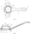
- a typical structure of the respiratory mask includes a frame, a cushion, an elbow, a connector, a headband, and so on.
- the cushion is fixed to the frame so that a gas chamber is formed by the cushion together with the frame, the elbow is connected to the frame through the connector to deliver a therapeutic gas into the gas chamber, and the headband is connected to the patient's head to fix the respiratory mask at a proper position of the patient's head.
- the cushion is in contact with the patient's face to achieve sealing against the face, and the patient's mouth and/or nose are located in the gas chamber.
- the respiratory mask Since respiratory exhaust gas needs to be discharged out of a respiratory mask during use thereof, the respiratory mask is usually provided with exhaust holes in order to discharge the respiratory exhaust gas smoothly.
- the exhaust holes in the existing respiratory masks are usually provided in an elbow or frame. In order to ensure a volume of exhaust gas, these exhaust holes usually have a large hole diameter; therefore, the respiratory mask has a louder exhaust noise and the discharged gas will affect the bed partner.
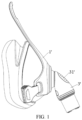
- some existing respiratory masks are provided with small holes for discharging the gas, such as the respiratory masks shown in FIGS. 1 and 2 , in which small exhaust holes 31' are centralizedly arranged in clusters in the elbow 3' (see FIG. 1 ) or in the frame 1' (see FIG. 2 ).
- small exhaust holes 31' are centralizedly arranged in clusters in the elbow 3' (see FIG. 1 ) or in the frame 1' (see FIG. 2 ).
- the diameter and molding of the small holes are greatly affected by molds, it is difficult to produce the holes and the cost is high; and due to spatial limitations, the direction in which the small holes discharge the gas will still blow the airflow to the bed partner, thus affecting sleeping quality of the patient himself/herself and the bed partner.
- AU 2015 234 317 A1 and WO 2013/006899 A1 disclose a swivel elbow and connector assembly for a respiratory mask and a respiratory mask with a cushion, a swivel elbow and a connector.
- the swivel elbow and connector assembly comprises a vented elbow connector and a swivel elbow.
- a sleeve is provided between a first end of the swivel elbow and the vented elbow ring.
- the vented elbow ring comprises an inner flange and an outer flange, which define a channel.
- a cushion of the respiratory mask may be fitted into the channel.
- the respiratory mask may further include a frame that supports the cushion.
- the vented elbow ring comprises a plurality of vent slots that extend through the inner flange across the channel and through the outer flange.
- the sleeve and the vented elbow ring provide a plurality of vents for venting of exhalation gases from the interior of the cushion to the exterior of the cushion through the vent slots.
- the cushion comprises a flexible base with an aperture for sealingly receiving a ring.
- the elbow comprises a tapered flanged for securing the elbow to the connector.
- the elbow further includes an angled flange intermediate its first and second end. The angled flanged of the elbow has a plurality of vents spaced around the angled flange.
- US 2018/104431 A1 also shows a respiratory mask and, in particular, a vent arrangement for the mask to discharge exhaled gas from the mask to atmosphere.
- An elbow of the mask includes a slot around its perimeter to receive a vent ring.
- the bottom wall of the slot of the elbow includes openings for gas washout and each sidewall of the slot includes a plurality of tracks or grooves.
- the vent ring forms a seal with the elbow so that air can only exhaust between the vent ring and the grooves on the elbow.
- An object of the present disclosure is to provide a respiratory mask and a ventilation therapy apparatus with the respiratory mask, so as to reduce the exhaust noise of the respiratory mask and meanwhile prevent the discharged airflow from being blown to the bed partner.
- an aspect of the present disclosure provides a respiratory mask
- the respiratory mask comprises a cushion assembly, an elbow assembly, and a connecting assembly arranged between the cushion assembly and the elbow assembly
- the cushion assembly comprises a cup
- the connecting assembly comprises a frame and a connector
- the elbow assembly comprises an elbow
- an exhaust passage is formed between the connector and the frame, and the exhaust passage is arranged to be able to guide a respiratory exhaust gas to be diverged and discharged all around the elbow
- the connector has an outer wall surface for connecting with the frame, and the exhaust passage is formed between the outer wall surface and the frame.
- an exhaust passage is provided between a connector and a frame, and the exhaust passage is arranged to guide respiratory exhaust gas to be diverged and discharged all around an elbow, so that no matter which direction a patient wearing the respiratory mask faces, the airflow would not be blown to his/her bed partner.
- the exhaust noise can be reduced effectively.
- the frame comprises an installation cavity for installing the connector, the installation cavity comprises a cylindrical cavity and a truncated cone cavity that are coaxial and in communication with each other, the truncated cone cavity is arranged close to the elbow, and the frame further comprises a first wall surface for defining the cylindrical cavity and a second wall surface for defining the truncated cone cavity; and the outer wall surface of the connector comprises a cylindrical surface corresponding to the first wall surface and a truncated cone surface corresponding to the second wall surface, gaps are provided in a radial direction of the installation cavity between the first wall surface and the cylindrical surface as well as between the second wall surface and the truncated cone surface, and the gaps form the exhaust passage.
- the rear exhaust section is formed into a horn shape surrounding the elbow, so that the respiratory exhaust gas is diverged and discharged all around the elbow.
- a diameter of the truncated cone cavity increases gradually in a direction away from the cylindrical cavity, and the first wall surface and the second wall surface are transitionally connected by a first arc; and/or the cylindrical surface and the truncated cone surface are transitionally connected by a second arc.
- a diameter of the truncated cone cavity increases gradually in a direction away from the cylindrical cavity, and the first wall surface and the second wall surface are transitionally connected by a first arc; and/or the cylindrical surface and the truncated cone surface are transitionally connected by a second arc.
- an included angle ⁇ between a generatrix of the truncated cone cavity and a bottom surface of the truncated cone cavity is 0°-75°, preferably 10°-30°.
- the included angle of this range may prevent the discharged airflow from disturbing the bed partner.
- a second protrusion is protrudingly formed on the truncated cone surface, and a second surface of the second protrusion facing away from the truncated cone surface is arranged to abut against the second wall surface; or a second protrusion is protrudingly formed on the second wall surface, and a second surface of the second protrusion facing away from the second wall surface is arranged to abut against the truncated cone surface.
- the second protrusion may improve the reliability of assembling the connector with the frame and reduce the degree of freedom of an axial movement of the connector after assembly.
- a generatrix of the truncated cone surface is parallel to a generatrix of the truncated cone cavity, and a protruding height of the second protrusion is 0.05mm-0.6mm, preferably 0.05mm-0.2mm; and/or the truncated cone surface or the second wall surface is provided with a plurality of the second protrusions spaced apart in a circumferential direction of the truncated cone surface or the second wall surface.
- the second protrusions may further enhance the above effect.
- the connector is connected to the frame through a snap-fit structure
- the snap-fit structure comprises a first buckle provided on the outer wall surface and a second buckle provided on the frame and fitting with the first buckle.
- the first buckle is an annular boss protrudingly formed on the cylindrical surface and extending in a circumferential direction of the cylindrical surface
- the second buckle is a first protrusion protrudingly formed on the first wall surface and the connector bears against the first protrusion through the annular boss.
- a width of the first protrusion gradually increases in a direction toward the annular boss in an axial direction of the cylindrical cavity, to achieve a firm snap-fit with the annular boss, and increase the ability of bearing pressure of the first protrusion, which may facilitate discharge of the respiratory exhaust gas; and/or an end of a first surface of the first protrusion facing away from the first wall surface, which is close to the second wall surface, extends to the second wall surface and the end is coplanar with the second wall surface, to achieve a smooth transition of the airflow between the front exhaust section and the rear exhaust section.
- a plurality of the first protrusions is provided on the first wall surface, and the plurality of the first protrusions is spaced apart in a circumferential direction of the first wall surface; and/or the respiratory mask comprises an anti-rotation structure for preventing the connector from rotating relative to the frame, which may prevent the connector from rotating relative to the frame.
- the anti-rotation structure comprises a flange protrudingly formed on the cylindrical surface and a groove formed on the first protrusion for embedding by the flange.
- a respiratory mask comprising a cushion assembly, an elbow assembly, and a connecting assembly arranged between the cushion assembly and the elbow assembly, wherein the connecting assembly comprises a frame and a connector, the elbow assembly comprises an elbow, an exhaust passage is formed between the connector and the frame, and the exhaust passage is arranged to be able to guide a respiratory exhaust gas to be diverged and discharged all around the elbow. So that no matter which direction a patient wearing the respiratory mask faces, the airflow would not be blown to his/her bed partner. In addition, since the airflow is diverged and discharged in an annular manner, the exhaust noise can be reduced effectively.
- a ventilation therapy apparatus comprising a host for generating a therapeutic gas, and a respiratory mask in communication with a gas outlet of the host, wherein the respiratory mask is the above respiratory mask.
- an exhaust passage is provided between a connector and a frame, and the exhaust passage is arranged to guide respiratory exhaust gas to be diverged and discharged all around an elbow, so that no matter which direction a patient wearing the respiratory mask faces, the airflow would not be blown to his/her bed partner.
- the exhaust noise can be reduced effectively.
- orientations such as “top” and “bottom” refer to the orientations shown in FIG. 1 .
- Terms “inside” and “outside” refers to the inside and outside relative to the contour of each component itself.
- An aspect of the present disclosure provides a respiratory mask, which includes a cushion assembly, an elbow assembly, and a connecting assembly arranged between the cushion assembly and the elbow assembly.
- the cushion assembly includes a cup 6, the connecting assembly includes a frame 1 and a connector 2, and the elbow assembly includes an elbow 3.
- An exhaust passage 4 is formed between the connector 2 and the frame 1, and the exhaust passage 4 is arranged to be able to guide a respiratory exhaust gas to be diverged and discharged all around the elbow 3.
- the respiratory mask of the present disclosure can prevent an airflow from being blown to the bed partner no matter which direction a patient wearing the respiratory mask is facing, and because the airflow is diverged and discharged in an annular manner, the exhaust noise can be effectively reduced.
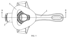
- the cushion assembly may further include a cushion 5 installed on a side of the cup 6 facing away from the frame 1.
- the cushion 5, the cup 6 and the frame 1 together form a gas chamber, and the elbow 3 is connected with the frame 1 through the connector 2 to deliver a gas into the gas chamber.
- the cushion 5 is in contact with a patient's face and achieves sealing against the face.
- the patient's mouth and/or nose are located in the gas chamber. Therefore, the exhaust passage 4 is in communication with the gas chamber, and the respiratory exhaust gas generated by the patient will first enter the gas chamber, and then is discharged through the exhaust passage 4.
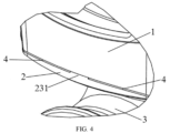
- the respiratory exhaust gas is diverged and discharged all around the elbow 3, which may be understood in the following way: the respiratory exhaust gas is discharged in a circumferential direction of the elbow 3 and at a certain angle with an axial direction of the elbow 3.
- the circumferential direction and the axial direction of the elbow 3 are defined with respect to an end of the elbow 3 that is connected to the connector 2 (see FIGS. 3 and 4 ).
- the connector 2 and the elbow 3 may each be a single piece, or the connector 2 and the elbow 3 may also be integral.
- the connector 2 may be made of polypropylene (PP) material or polycarbonate (PC) material.
- PP polypropylene
- PC polycarbonate
- the connector 2 is less rigid than the frame 1 and/or the elbow 3, so as to reduce abnormal sound caused by rotation between the elbow 3 and the frame 1 and increase smoothness of the rotation.
- the cup 6 may include an interface portion 61, and the cup 6 may be connected to a connecting assembly through the interface portion 61.
- the exhaust passage 4 may be arranged between the interface portion 61 and the frame 1.
- the interface portion 61 may be arranged to extend from the cup 6 toward a connection side of the connecting assembly (see FIG. 6 ), or extend from the cup 6 in a direction away from the connection side of the connecting assembly.
- the interface portion 61 is arranged to extend from the cup 6 in the direction away from the connection side of the connecting assembly so as to improve connection stability between the interface portion 61 and the connecting assembly and to reduce a volume of the respiratory mask.
- the connector 2 may have an inner wall surface 21 for connecting with the elbow 3 and an outer wall surface for connecting with the frame 1.
- the exhaust passage 4 may be formed between the outer wall surface and the frame 1.
- the frame 1 may include an installation cavity for installing the connector 2.
- the installation cavity includes a cylindrical cavity and a truncated cone cavity that are coaxial and in communication with each other.
- the truncated cone cavity is located close to the elbow 3 (i.e., a lower end shown in FIG. 9 ), and has a diameter increasing gradually in a direction away from the cylindrical cavity (i.e., from top to bottom as shown in FIG. 9 ).
- the frame 1 further includes a first wall surface 11 for defining the cylindrical cavity and a second wall surface 12 for defining the truncated cone cavity; as shown in FIGS.
- the outer wall surface of the connector 2 may include a cylindrical surface 22 corresponding to the first wall surface 11 and a truncated cone surface 23 corresponding to the second wall surface 12. Gaps are provided in a radial direction of the installation cavity between the first wall surface 11 and the cylindrical surface 22 as well as between the second wall surface 12 and the truncated cone surface 23. The gaps form the exhaust passage 4. It can be understood that the gap between the first wall surface 11 and the cylindrical surface 22 and the gap between the second wall surface 12 and the truncated cone surface 23 are in communication with each other.
- the exhaust passage 4 may include a front exhaust section 41 formed by the gap between the first wall surface 11 and the cylindrical surface 22, and a rear exhaust section 42 formed by the gap between the second wall surface 12 and the truncated cone surface 23.
- the respiratory exhaust gas first enters the front exhaust section 41 through the gas chamber, then enters the rear exhaust section 42, and is discharged from the rear exhaust section 42.
- the rear exhaust section 42 With the structural features of the second wall surface 12 and the truncated cone surface 23, the rear exhaust section 42 is formed into a horn shape surrounding the elbow 3, so that the respiratory exhaust gas is diverged and discharged all around the elbow 3.
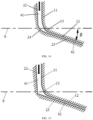
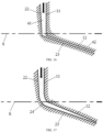
- the exhaust passage 4 may have various cross-sectional shapes, such as those shown in FIGS. 14-18 , according to the difference in the transition modes between the first wall surface 11 and the second wall surface 12 as well as between the cylindrical surface 22 and the truncated cone surface 23, and the difference in an extending direction of a generatrix of the truncated cone surface 23 and that of the second wall surface 12.
- the first wall surface 11 and the second wall surface 12 are transitionally connected by a first arc 13 so that the cylindrical surface 22 is transitionally connected to the truncated cone surface 23 by a second arc 24 (see FIGS.
- a width of the front exhaust section 41 larger than a width of the rear exhaust section 42, for example, as shown in FIG. 14 .
- a plane approximately parallel to the patient's face may be denoted as a plane S.
- the front exhaust section 41 is connected with the nose of the patient.
- the front exhaust section 41 with a larger width facilitates discharge of the respiratory exhaust gas
- the rear exhaust section 42 with a smaller width facilitates controlling the volume of exhaust gas and reducing the exhaust noise.
- the generatrix of the truncated cone cavity forms an angle ⁇ with a bottom surface of the truncated cone cavity (which is parallel to the plane S).
- ⁇ may be 0-75°, preferably 10-30°. It can be understood that by adjusting the width of the rear exhaust section 42, the volume of exhaust gas can be adjusted and the exhaust noise can be reduced, and by adjusting the angle between the rear exhaust section 42 and the plane S, an adjustment of the exhaust direction can be achieved.
- a second protrusion 231 may be protrudingly formed on the truncated cone surface 23, and a second surface of the second protrusion 231 facing away from the truncated cone surface 23 is arranged to abut against the second wall surface 12; or a second protrusion 231 is protrudingly formed on the second wall surface 12, and a second surface of the second protrusion 231 facing away from the second wall surface 12 is arranged to abut against the truncated cone surface 23.
- the second protrusion 231 is provided in the rear exhaust section 42 and supported between the truncated cone surface 23 and the second wall surface 12.
- a protruding height of the second protrusion 231 determines the width of the rear exhaust section 42.
- the generatrix of the truncated cone surface 23 may be set parallel to the generatrix of the truncated cone cavity.
- the protruding height of the second protrusion 231 (that is, the width of the rear exhaust section 42) may be 0.05mm-0.6mm, preferably 0.05mm-0.2mm.
- a plurality of the second protrusions 231 may be provided on the truncated cone surface 23 or the second wall surface 12, which are spaced apart in a circumferential direction of the truncated cone surface 23 or the second wall surface 12 (see FIG. 12 ). In this case, the plurality of second protrusions 231 may divide the rear exhaust section 42 into a plurality of fan-shaped passages.
- the connector 2 may be connected to the frame 1 through a snap-fit structure, and the snap-fit structure may include a first buckle provided on the outer wall surface and a second buckle provided on the frame 1 and fitting the first buckle.
- the first buckle is an annular boss 221 protrudingly formed on the cylindrical surface 22 and extending in a circumferential direction of the cylindrical surface 22.
- the second buckle is a first protrusion 111 protrudingly formed on the first wall surface 11.
- the connector 2 bears against the first protrusion 111 through the annular boss 221.
- an upper end of the connector 2 may be inserted into the installation cavity of the frame 1 from bottom to top, so that the annular boss 221 is clamped above the first protrusion 111 (for bearing an axial pull-off force).
- a width of the annular boss 221 may be set to 0.1mm-1mm, preferably 0.2mm-0.6mm.
- a first surface 112 of the first protrusion 111 facing away from the first wall surface 11 may be arranged to abut against the cylindrical surface 22, so that the first protrusion 111 can be supported between the first wall surface 11 and the cylindrical surface 22, thereby ensuring the reliability of assembling the connector 2 and the frame 1 and reducing the degree of freedom of the movement of the connector 2 after assembly.
- a protruding height of the first protrusion 111 may determine the width of the front exhaust section 41.
- a width of the first protrusion 111 may be set to gradually increase in a direction toward the annular boss 221 (that is, the direction from bottom to top) in an axial direction of the cylindrical cavity. That is, the first protrusion 111 is structured with a wide upper part and a narrow lower part, and an included angle between a side surface 114 of the first protrusion 111 and a vertical direction may be 2°-6°.
- an included angle between a side surface 114 of the first protrusion 111 and a vertical direction may be 2°-6°.
- an end of the first surface 112 of the first protrusion 111 facing away from the first wall surface 11, which is close to the second wall surface 12 (i.e., a lower end of the first surface 112), may extend to the second wall surface 12 and may be coplanar with the second wall surface 12.
- a plurality of the first protrusions 111 may be provided on the first wall surface 11, and the plurality of the first protrusions 111 may be spaced apart in the circumferential direction of the first wall surface 11 (see FIG. 8 ). It should be noted that the number of the first protrusions 111 may be equal to or different from the number of the second protrusions 231.
- the number of the first protrusions 111 is equal to the number of the second protrusions 231, and the plurality of the second protrusions 231 correspond to the plurality of the first protrusions 111 in a one-to-one correspondence in the axial direction of the installation cavity, which can improve the reliability of assembling the connector 2 and the frame 1, guarantee a balanced force and meanwhile divide the entire exhaust passage 4 into a plurality of spaced-out flow passages.
- the respiratory mask may further include an anti-rotation structure for preventing the connector 2 from rotating relative to the frame 1.
- the anti-rotation structure may be implemented in any way, to which the present disclosure does not impose any limitation.
- the anti-rotation structure may include a flange 222 protrudingly formed on the cylindrical surface 22 and a groove 113 formed on the first protrusion 111 for embedding by the flange 222.
- the groove 113 is provided on one of the first protrusions 111.
- a mark portion 27 may be provided on the connector 2, with a position of the mark portion 27 corresponding to the flange 222 in a vertical direction. In this way, the assembling speed of the connector 2 and the frame 1 can be accelerated.
- the elbow 3 may be ball-socket connected to the inner wall surface 21 of the connector 2.
- a first convex portion 25 may be provided on a bottom surface of the connector 2; in order to improve the strength of the connector 2, a second convex portion 26 may be provided on the bottom surface of the connector 2.
- the first convex portion 25 and the second convex portion 26 may be arranged to extend in the circumferential direction of the connector 2, and the first convex portion 25 and the second convex portion 26 may be respectively located at an inner rim and an outer rim of the bottom surface of the connector 2.
- a ventilation therapy apparatus which includes a host for generating a therapeutic gas and a respiratory mask in communication with a gas outlet of the host, and the respiratory mask is the above-mentioned respiratory mask.
- the ventilation therapy apparatus may be a respirator.
Landscapes
- Health & Medical Sciences (AREA)
- Emergency Medicine (AREA)
- Pulmonology (AREA)
- Engineering & Computer Science (AREA)
- Anesthesiology (AREA)
- Biomedical Technology (AREA)
- Heart & Thoracic Surgery (AREA)
- Hematology (AREA)
- Life Sciences & Earth Sciences (AREA)
- Animal Behavior & Ethology (AREA)
- General Health & Medical Sciences (AREA)
- Public Health (AREA)
- Veterinary Medicine (AREA)
- Otolaryngology (AREA)
- Respiratory Apparatuses And Protective Means (AREA)
Claims (10)
- Eine Beatmungsmaske, umfassend eine Kisseneinheit, eine Kniestückeinheit und eine zwischen der Kisseneinheit und der Kniestückeinheit angeordnete Verbindungseinheit, wobei die Verbindungseinheit einen Rahmen (1) und ein Verbinder (2) umfasst, die Kniestückeinheit ein Kniestück (3) umfasst, eine Auslasspassage (4) zwischen dem Verbinder (2) und dem Rahmen (1) ausgebildet ist und die Auslasspassage (4) so angeordnet ist, dass sie ein Ausatemgas so leiten kann, dass es ringsum das Kniestück (3) abgeleitet und ausgestoßen wird, dadurch gekennzeichnet, dass der Verbinder (2) eine Außenwandfläche zum Verbinden mit dem Rahmen (1) aufweist und die Auslasspassage (4) zwischen der Außenwandfläche und dem Rahmen (1) ausgebildet ist.
- Die Beatmungsmaske gemäß Anspruch 1, dadurch gekennzeichnet, dass die Kisseneinheit eine Schale (6) umfasst.
- Die Beatmungsmaske gemäß Anspruch 1 oder 2, dadurch gekennzeichnet, dassder Rahmen (1) einen Installationshohlraum zum Installieren des Verbinders (2) umfasst, der Installationshohlraum einen zylindrischen Hohlraum und einen kegelstumpfförmigen Hohlraum umfasst, die koaxial und in Verbindung miteinander sind, der kegelstumpfförmige Hohlraum nahe dem Kniestück (3) angeordnet ist und der Rahmen (1) ferner eine erste Wandfläche (11) zum Definieren des zylindrischen Hohlraums und eine zweite Wandfläche (12) zum Definieren des kegelstumpfförmigen Hohlraums umfasst; unddie Außenwandfläche des Verbinders (2) eine zylindrische Fläche (22) entsprechend der ersten Wandfläche (11) und eine Kegelstumpffläche (23) entsprechend der zweiten Wandfläche (12) umfasst, und in einer radialen Richtung des Installationshohlraums zwischen der ersten Wandfläche (11) und der zylindrischen Fläche (22) sowie zwischen der zweiten Wandfläche (12) und der Kegelstumpffläche (23) Spalte vorgesehen sind und die Spalte die Auslasspassage (4) bilden.
- Die Beatmungsmaske gemäß Anspruch 3, dadurch gekennzeichnet, dass ein Durchmesser des kegelstumpfförmigen Hohlraums in einer Richtung weg von dem zylindrischen Hohlraum allmählich zunimmt und die erste Wandfläche (11) und die zweite Wandfläche (12) im Übergangsbereich durch einen ersten Bogen (13) verbunden sind; und/oder
die zylindrische Fläche (22) und die Kegelstumpffläche (23) im Übergangsbereich durch einen zweiten Bogen (24) verbunden sind. - Die Atemmaske gemäß Anspruch 3, dadurch gekennzeichnet, dass ein eingeschlossener Winkel β zwischen einer Erzeugenden des kegelstumpfförmigen Hohlraums und einer Bodenfläche des kegelstumpfförmigen Hohlraums 0°-75°, vorzugsweise 10°-30°, beträgt.
- Die Atemmaske gemäß Anspruch 3, dadurch gekennzeichnet, dass ein zweiter Vorsprung (231) vorstehend auf der Kegelstumpffläche (23) ausgebildet ist und eine von der Kegelstumpffläche (23) weg weisende zweite Fläche des zweiten Vorsprungs (231) so angeordnet ist, dass sie an der zweiten Wandfläche (12) anliegt; oder ein zweiter Vorsprung (231) vorstehend auf der zweiten Wandfläche (12) ausgebildet ist, und eine von der zweiten Wandfläche (12) weg weisende zweite Fläche des zweiten Vorsprungs (231) so angeordnet ist, dass sie an der Kegelstumpffläche (23) anliegt; und vorzugsweiseeine Erzeugende der Kegelstumpffläche (23) parallel zu einer Erzeugenden des kegelstumpfförmigen Hohlraums ist, und eine vorstehende Höhe des zweiten Vorsprungs (231) 0,05 mm bis 0,6 mm, vorzugsweise 0,05 mm bis 0,2 mm beträgt; und/oderdie Kegelstumpffläche (23) oder die zweite Wandfläche (12) mit einer Mehrzahl der zweiten Vorsprünge (231) versehen ist, die in Umfangsrichtung der Kegelstumpffläche (23) oder der zweiten Wandfläche (12) voneinander beabstandet sind.
- Die Beatmungsmaske gemäß einem der Ansprüche 3 bis 6, dadurch gekennzeichnet, dass der Verbinder (2) mit dem Rahmen (1) durch eine Schnappverbindung verbunden ist und die Schnappverbindung eine an der äußeren Wandfläche vorgesehene erste Schnalle und eine an dem Rahmen (1) vorgesehene und mit der ersten Schnalle zusammenpassende zweite Schnalle umfasst;
die erste Schnalle vorzugsweise ein auf der zylindrischen Oberfläche (22) vorstehend ausgebildeter und sich in einer Umfangsrichtung der zylindrischen Oberfläche (22) erstreckender ringförmiger Vorsprung (221) ist, die zweite Schnalle vorzugsweise ein auf der ersten Wandfläche (11) vorstehend ausgebildeter erster Vorsprung (111) ist und der Verbinder (2) mittels des ringförmigen Vorsprungs (221) an dem ersten Vorsprung (111) anliegt. - Die Beatmungsmaske gemäß Anspruch 7, dadurch gekennzeichnet, dass:
eine Breite des ersten Vorsprungs (111) in einer Richtung hin zu dem ringförmigen Vorsprung (221) in einer axialen Richtung des zylindrischen Hohlraums allmählich zunimmt; und/oder ein nahe der zweiten Wandfläche (12) liegendes Ende einer von der ersten Wandfläche (11) weg weisenden ersten Fläche (112) des ersten Vorsprungs (111) sich bis zur zweiten Wandfläche (12) erstreckt und das Ende koplanar mit der zweiten Wandfläche (12) ist. - Die Atemmaske gemäß Anspruch 7, dadurch gekennzeichnet, dass eine Mehrzahl der ersten Vorsprünge (111) auf der ersten Wandfläche (11) vorgesehen ist und die Mehrzahl der ersten Vorsprünge (111) in einer Umfangsrichtung der ersten Wandfläche (11) voneinander beabstandet sind; und/oder
die Atemmaske eine Drehsicherungsstruktur umfasst, um zu verhindern, dass sich der Verbinder (2) relativ zum Rahmen (1) dreht, wobei die Drehsicherungsstruktur vorzugsweise einen auf der zylindrischen Oberfläche (22) vorstehend ausgebildeten Flansch (222), und eine auf dem ersten Vorsprung (111) ausgebildete Nut (113) umfasst und die Nut (113) ausgebildet ist, um den Flansch (222) einzubetten. - Beatmungsgerät, umfassend einen Generator zur Erzeugung eines therapeutischen Gases und eine Beatmungsmaske, die mit einem Gasauslass des Generators in Verbindung steht, wobei die Beatmungsmaske die Beatmungsmaske gemäß einem der Ansprüche 1 bis 9 ist.
Applications Claiming Priority (2)
| Application Number | Priority Date | Filing Date | Title |
|---|---|---|---|
| CN201811646330.2A CN109568756A (zh) | 2018-12-29 | 2018-12-29 | 呼吸面罩和通气治疗设备 |
| PCT/CN2019/129341 WO2020135760A1 (zh) | 2018-12-29 | 2019-12-27 | 呼吸面罩和通气治疗设备 |
Publications (3)
| Publication Number | Publication Date |
|---|---|
| EP3900766A1 EP3900766A1 (de) | 2021-10-27 |
| EP3900766A4 EP3900766A4 (de) | 2022-02-09 |
| EP3900766B1 true EP3900766B1 (de) | 2025-01-22 |
Family
ID=65914897
Family Applications (1)
| Application Number | Title | Priority Date | Filing Date |
|---|---|---|---|
| EP19904717.6A Active EP3900766B1 (de) | 2018-12-29 | 2019-12-27 | Atemmaske und beatmungstherapievorrichtung |
Country Status (5)
| Country | Link |
|---|---|
| US (1) | US12508383B2 (de) |
| EP (1) | EP3900766B1 (de) |
| JP (1) | JP7203463B2 (de) |
| CN (1) | CN109568756A (de) |
| WO (1) | WO2020135760A1 (de) |
Families Citing this family (8)
| Publication number | Priority date | Publication date | Assignee | Title |
|---|---|---|---|---|
| CN109568756A (zh) * | 2018-12-29 | 2019-04-05 | 天津觉明科技有限公司 | 呼吸面罩和通气治疗设备 |
| CN110975096A (zh) * | 2019-12-31 | 2020-04-10 | 北京怡和嘉业医疗科技股份有限公司 | 安全阀片、呼吸管、呼吸管组件和呼吸面罩 |
| CN111110974B (zh) * | 2019-12-31 | 2025-11-04 | 北京瑞迈特医疗科技股份有限公司 | 流量调节装置及流量可调节的呼吸面罩 |
| CN112089943A (zh) * | 2020-09-18 | 2020-12-18 | 北京怡和嘉业医疗科技股份有限公司 | 通气保湿装置、呼吸面罩、呼吸面罩组件和呼吸支持设备 |
| DE102022106734A1 (de) * | 2021-04-09 | 2022-10-13 | Löwenstein Medical Technology S.A. | Ausatemsystem und Kugelgelenk für eine Patientenschnittstelle |
| CN215024377U (zh) * | 2021-04-13 | 2021-12-07 | 天津怡和嘉业医疗科技有限公司 | 通气降噪壳体和组件、通气保湿装置、呼吸面罩组件和呼吸支持设备 |
| CN113893424A (zh) * | 2021-09-30 | 2022-01-07 | 天津怡和嘉业医疗科技有限公司 | 排气组件及呼吸面罩 |
| CN117653850A (zh) * | 2023-10-17 | 2024-03-08 | 天津怡和嘉业医疗科技有限公司 | 一种呼吸面罩及通气设备 |
Family Cites Families (27)
| Publication number | Priority date | Publication date | Assignee | Title |
|---|---|---|---|---|
| US6412487B1 (en) * | 1997-01-31 | 2002-07-02 | Resmed Limited | Mask cushion and frame assembly |
| NZ605941A (en) * | 2002-09-06 | 2014-07-25 | Resmed Ltd | Elbow for mask assembly |
| AU2003257273A1 (en) * | 2002-09-06 | 2004-03-29 | Resmed Limited | Elbow for mask assembly |
| US20050199240A1 (en) * | 2003-01-09 | 2005-09-15 | Matthew Hall | Flexible full-face mask for CPAP treatment |
| DE202004021829U1 (de) * | 2003-05-02 | 2011-05-26 | ResMed Ltd., New South Wales | Ein Maskensystem |
| WO2006024288A2 (de) * | 2004-09-03 | 2006-03-09 | Weinmann Geräte für Medizin GmbH & Co. KG | Atemmaske |
| JP2008526394A (ja) * | 2005-01-12 | 2008-07-24 | レスメド リミテッド | ガス逃がし通気孔を有する呼吸マスクおよびマスクの製造方法 |
| US20070181130A1 (en) * | 2006-02-06 | 2007-08-09 | Worley Brian D | Ventilator to tracheotomy tube coupling |
| EP3738636B1 (de) * | 2006-07-14 | 2023-06-07 | Fisher & Paykel Healthcare Limited | Atemhilfsgerät |
| EP3858411B1 (de) * | 2007-08-24 | 2024-05-29 | ResMed Pty Ltd | Maskenluftdurchlass |
| NZ617661A (en) * | 2009-05-29 | 2015-05-29 | Resmed Ltd | Nasal mask system |
| JP5879354B2 (ja) | 2010-10-14 | 2016-03-08 | ヴェンティフック ホールディングス ピーティーワイ リミテッドVentific Holdings Pty Ltd | 呼吸弁装置 |
| EP2629822B1 (de) | 2010-10-22 | 2018-10-10 | Koninklijke Philips N.V. | Patientenschnittstelle mit einer entlüftung |
| WO2012123891A1 (en) | 2011-03-14 | 2012-09-20 | Koninklijke Philips Electronics N.V. | Patient interface device having fabric pouch for a cushion cross-reference to related applications |
| CA2833106C (en) * | 2011-04-15 | 2019-08-27 | Fisher & Paykel Healthcare Limited | Interface comprising a rolling nasal bridge portion |
| WO2013006899A1 (en) | 2011-07-08 | 2013-01-17 | Resmed Limited | Swivel elbow and connector assembly for patient interface systems |
| AU2015234317A1 (en) | 2011-07-08 | 2015-10-22 | Resmed Limited | Swivel Elbow and Connector Assembly for Patient Interface Systems |
| WO2014129913A1 (en) | 2013-02-21 | 2014-08-28 | Fisher & Paykel Healthcare Limited | Patient interface with venting |
| EP2818195B1 (de) * | 2013-06-27 | 2019-05-22 | Air Liquide Medical Systems | Pädiatrische atemmaske mit kugelkopfverbinder |
| CN204890882U (zh) * | 2015-06-23 | 2015-12-23 | 北京怡和嘉业医疗科技有限公司 | 一种面罩组件 |
| CN105079933B (zh) | 2015-06-23 | 2018-05-29 | 北京怡和嘉业医疗科技股份有限公司 | 一种面罩组件 |
| EP3352829B1 (de) * | 2015-09-23 | 2022-12-28 | ResMed Pty Ltd | Ellbogenanordnung |
| EP3352825B1 (de) * | 2015-09-23 | 2020-12-16 | ResMed Pty Ltd | Patientenschnittstelle |
| CN105413035A (zh) * | 2015-12-24 | 2016-03-23 | 北京怡和嘉业医疗科技有限公司 | 用于呼吸面罩的衬垫和呼吸面罩 |
| EP3300761A1 (de) * | 2016-10-03 | 2018-04-04 | Air Liquide Medical Systems | Hohlverbinder mit entgasungssystem für atemmaske |
| CN109568756A (zh) | 2018-12-29 | 2019-04-05 | 天津觉明科技有限公司 | 呼吸面罩和通气治疗设备 |
| CN209864957U (zh) * | 2018-12-29 | 2019-12-31 | 天津觉明科技有限公司 | 呼吸面罩和通气治疗设备 |
-
2018
- 2018-12-29 CN CN201811646330.2A patent/CN109568756A/zh active Pending
-
2019
- 2019-12-27 JP JP2021538481A patent/JP7203463B2/ja active Active
- 2019-12-27 WO PCT/CN2019/129341 patent/WO2020135760A1/zh not_active Ceased
- 2019-12-27 EP EP19904717.6A patent/EP3900766B1/de active Active
- 2019-12-27 US US17/419,498 patent/US12508383B2/en active Active
Also Published As
| Publication number | Publication date |
|---|---|
| US20220088336A1 (en) | 2022-03-24 |
| US12508383B2 (en) | 2025-12-30 |
| JP2022516158A (ja) | 2022-02-24 |
| WO2020135760A1 (zh) | 2020-07-02 |
| CN109568756A (zh) | 2019-04-05 |
| EP3900766A4 (de) | 2022-02-09 |
| JP7203463B2 (ja) | 2023-01-13 |
| EP3900766A1 (de) | 2021-10-27 |
Similar Documents
| Publication | Publication Date | Title |
|---|---|---|
| EP3900766B1 (de) | Atemmaske und beatmungstherapievorrichtung | |
| US20260054024A1 (en) | Vent for a component of a respiratory therapy system | |
| EP2979719B1 (de) | Ausatemvorrichtung für ein patienteninterface | |
| AU2022203660B2 (en) | Pressure Controlled Exhaust Vent | |
| JP3961425B2 (ja) | 圧力支援システムの排気口組立体 | |
| US6561191B1 (en) | Mask and a vent assembly therefor | |
| EP2849828B1 (de) | Dichtungskissen und patientenschnittstellenvorrichtung damit | |
| JP2009512536A (ja) | 一体型緩衝体鼻枕を有する患者界面材 | |
| JP2012511372A (ja) | 排気構造 | |
| CN106999686A (zh) | 用于与通风和空气正压系统一起使用的混合气道正压接口系统 | |
| WO2017067082A1 (zh) | 通气控制装置和具有该通气控制装置的呼吸面罩设备 | |
| CN209864957U (zh) | 呼吸面罩和通气治疗设备 | |
| CN113893424A (zh) | 排气组件及呼吸面罩 | |
| CN216777696U (zh) | 排气组件及呼吸面罩 | |
| CN112638458A (zh) | 鼻部分和包括该鼻部分的患者界面装置 | |
| CN219700745U (zh) | 排气结构及呼吸面罩 | |
| EP4552675A3 (de) | Patientenschnittstelle mit schaumstoffpolster | |
| CN112915344A (zh) | 呼吸面罩 |
Legal Events
| Date | Code | Title | Description |
|---|---|---|---|
| STAA | Information on the status of an ep patent application or granted ep patent |
Free format text: STATUS: THE INTERNATIONAL PUBLICATION HAS BEEN MADE |
|
| PUAI | Public reference made under article 153(3) epc to a published international application that has entered the european phase |
Free format text: ORIGINAL CODE: 0009012 |
|
| STAA | Information on the status of an ep patent application or granted ep patent |
Free format text: STATUS: REQUEST FOR EXAMINATION WAS MADE |
|
| 17P | Request for examination filed |
Effective date: 20210722 |
|
| AK | Designated contracting states |
Kind code of ref document: A1 Designated state(s): AL AT BE BG CH CY CZ DE DK EE ES FI FR GB GR HR HU IE IS IT LI LT LU LV MC MK MT NL NO PL PT RO RS SE SI SK SM TR |
|
| A4 | Supplementary search report drawn up and despatched |
Effective date: 20220112 |
|
| RIC1 | Information provided on ipc code assigned before grant |
Ipc: A61M 16/08 20060101ALI20220105BHEP Ipc: A61M 16/00 20060101ALI20220105BHEP Ipc: A61M 16/06 20060101AFI20220105BHEP |
|
| DAV | Request for validation of the european patent (deleted) | ||
| DAX | Request for extension of the european patent (deleted) | ||
| RAP3 | Party data changed (applicant data changed or rights of an application transferred) |
Owner name: CAREMEDI TECHNOLOGY CO., LTD. |
|
| STAA | Information on the status of an ep patent application or granted ep patent |
Free format text: STATUS: EXAMINATION IS IN PROGRESS |
|
| 17Q | First examination report despatched |
Effective date: 20240119 |
|
| GRAP | Despatch of communication of intention to grant a patent |
Free format text: ORIGINAL CODE: EPIDOSNIGR1 |
|
| STAA | Information on the status of an ep patent application or granted ep patent |
Free format text: STATUS: GRANT OF PATENT IS INTENDED |
|
| RIC1 | Information provided on ipc code assigned before grant |
Ipc: A61M 16/08 20060101ALI20240712BHEP Ipc: A61M 16/06 20060101AFI20240712BHEP |
|
| INTG | Intention to grant announced |
Effective date: 20240725 |
|
| RAP3 | Party data changed (applicant data changed or rights of an application transferred) |
Owner name: CAREMEDI TECHNOLOGY CO., LTD. |
|
| GRAS | Grant fee paid |
Free format text: ORIGINAL CODE: EPIDOSNIGR3 |
|
| P01 | Opt-out of the competence of the unified patent court (upc) registered |
Free format text: CASE NUMBER: APP_60696/2024 Effective date: 20241112 |
|
| GRAA | (expected) grant |
Free format text: ORIGINAL CODE: 0009210 |
|
| STAA | Information on the status of an ep patent application or granted ep patent |
Free format text: STATUS: THE PATENT HAS BEEN GRANTED |
|
| AK | Designated contracting states |
Kind code of ref document: B1 Designated state(s): AL AT BE BG CH CY CZ DE DK EE ES FI FR GB GR HR HU IE IS IT LI LT LU LV MC MK MT NL NO PL PT RO RS SE SI SK SM TR |
|
| REG | Reference to a national code |
Ref country code: GB Ref legal event code: FG4D |
|
| REG | Reference to a national code |
Ref country code: CH Ref legal event code: EP |
|
| REG | Reference to a national code |
Ref country code: IE Ref legal event code: FG4D |
|
| REG | Reference to a national code |
Ref country code: DE Ref legal event code: R096 Ref document number: 602019065265 Country of ref document: DE |
|
| REG | Reference to a national code |
Ref country code: NL Ref legal event code: MP Effective date: 20250122 |
|
| PG25 | Lapsed in a contracting state [announced via postgrant information from national office to epo] |
Ref country code: NL Free format text: LAPSE BECAUSE OF FAILURE TO SUBMIT A TRANSLATION OF THE DESCRIPTION OR TO PAY THE FEE WITHIN THE PRESCRIBED TIME-LIMIT Effective date: 20250122 |
|
| PG25 | Lapsed in a contracting state [announced via postgrant information from national office to epo] |
Ref country code: RS Free format text: LAPSE BECAUSE OF FAILURE TO SUBMIT A TRANSLATION OF THE DESCRIPTION OR TO PAY THE FEE WITHIN THE PRESCRIBED TIME-LIMIT Effective date: 20250422 |
|
| PG25 | Lapsed in a contracting state [announced via postgrant information from national office to epo] |
Ref country code: FI Free format text: LAPSE BECAUSE OF FAILURE TO SUBMIT A TRANSLATION OF THE DESCRIPTION OR TO PAY THE FEE WITHIN THE PRESCRIBED TIME-LIMIT Effective date: 20250122 |
|
| PG25 | Lapsed in a contracting state [announced via postgrant information from national office to epo] |
Ref country code: PL Free format text: LAPSE BECAUSE OF FAILURE TO SUBMIT A TRANSLATION OF THE DESCRIPTION OR TO PAY THE FEE WITHIN THE PRESCRIBED TIME-LIMIT Effective date: 20250122 |
|
| PG25 | Lapsed in a contracting state [announced via postgrant information from national office to epo] |
Ref country code: ES Free format text: LAPSE BECAUSE OF FAILURE TO SUBMIT A TRANSLATION OF THE DESCRIPTION OR TO PAY THE FEE WITHIN THE PRESCRIBED TIME-LIMIT Effective date: 20250122 |
|
| REG | Reference to a national code |
Ref country code: LT Ref legal event code: MG9D |
|
| PG25 | Lapsed in a contracting state [announced via postgrant information from national office to epo] |
Ref country code: NO Free format text: LAPSE BECAUSE OF FAILURE TO SUBMIT A TRANSLATION OF THE DESCRIPTION OR TO PAY THE FEE WITHIN THE PRESCRIBED TIME-LIMIT Effective date: 20250422 Ref country code: IS Free format text: LAPSE BECAUSE OF FAILURE TO SUBMIT A TRANSLATION OF THE DESCRIPTION OR TO PAY THE FEE WITHIN THE PRESCRIBED TIME-LIMIT Effective date: 20250522 |
|
| REG | Reference to a national code |
Ref country code: AT Ref legal event code: MK05 Ref document number: 1761016 Country of ref document: AT Kind code of ref document: T Effective date: 20250122 |
|
| PG25 | Lapsed in a contracting state [announced via postgrant information from national office to epo] |
Ref country code: HR Free format text: LAPSE BECAUSE OF FAILURE TO SUBMIT A TRANSLATION OF THE DESCRIPTION OR TO PAY THE FEE WITHIN THE PRESCRIBED TIME-LIMIT Effective date: 20250122 |
|
| PG25 | Lapsed in a contracting state [announced via postgrant information from national office to epo] |
Ref country code: LV Free format text: LAPSE BECAUSE OF FAILURE TO SUBMIT A TRANSLATION OF THE DESCRIPTION OR TO PAY THE FEE WITHIN THE PRESCRIBED TIME-LIMIT Effective date: 20250122 Ref country code: PT Free format text: LAPSE BECAUSE OF FAILURE TO SUBMIT A TRANSLATION OF THE DESCRIPTION OR TO PAY THE FEE WITHIN THE PRESCRIBED TIME-LIMIT Effective date: 20250522 |
|
| PG25 | Lapsed in a contracting state [announced via postgrant information from national office to epo] |
Ref country code: BG Free format text: LAPSE BECAUSE OF FAILURE TO SUBMIT A TRANSLATION OF THE DESCRIPTION OR TO PAY THE FEE WITHIN THE PRESCRIBED TIME-LIMIT Effective date: 20250122 Ref country code: GR Free format text: LAPSE BECAUSE OF FAILURE TO SUBMIT A TRANSLATION OF THE DESCRIPTION OR TO PAY THE FEE WITHIN THE PRESCRIBED TIME-LIMIT Effective date: 20250423 |
|
| PG25 | Lapsed in a contracting state [announced via postgrant information from national office to epo] |
Ref country code: AT Free format text: LAPSE BECAUSE OF FAILURE TO SUBMIT A TRANSLATION OF THE DESCRIPTION OR TO PAY THE FEE WITHIN THE PRESCRIBED TIME-LIMIT Effective date: 20250122 |
|
| PG25 | Lapsed in a contracting state [announced via postgrant information from national office to epo] |
Ref country code: SE Free format text: LAPSE BECAUSE OF FAILURE TO SUBMIT A TRANSLATION OF THE DESCRIPTION OR TO PAY THE FEE WITHIN THE PRESCRIBED TIME-LIMIT Effective date: 20250122 |
|
| PG25 | Lapsed in a contracting state [announced via postgrant information from national office to epo] |
Ref country code: SM Free format text: LAPSE BECAUSE OF FAILURE TO SUBMIT A TRANSLATION OF THE DESCRIPTION OR TO PAY THE FEE WITHIN THE PRESCRIBED TIME-LIMIT Effective date: 20250122 |
|
| PG25 | Lapsed in a contracting state [announced via postgrant information from national office to epo] |
Ref country code: DK Free format text: LAPSE BECAUSE OF FAILURE TO SUBMIT A TRANSLATION OF THE DESCRIPTION OR TO PAY THE FEE WITHIN THE PRESCRIBED TIME-LIMIT Effective date: 20250122 |
|
| PG25 | Lapsed in a contracting state [announced via postgrant information from national office to epo] |
Ref country code: IT Free format text: LAPSE BECAUSE OF FAILURE TO SUBMIT A TRANSLATION OF THE DESCRIPTION OR TO PAY THE FEE WITHIN THE PRESCRIBED TIME-LIMIT Effective date: 20250122 |
|
| PG25 | Lapsed in a contracting state [announced via postgrant information from national office to epo] |
Ref country code: EE Free format text: LAPSE BECAUSE OF FAILURE TO SUBMIT A TRANSLATION OF THE DESCRIPTION OR TO PAY THE FEE WITHIN THE PRESCRIBED TIME-LIMIT Effective date: 20250122 Ref country code: CZ Free format text: LAPSE BECAUSE OF FAILURE TO SUBMIT A TRANSLATION OF THE DESCRIPTION OR TO PAY THE FEE WITHIN THE PRESCRIBED TIME-LIMIT Effective date: 20250122 |
|
| REG | Reference to a national code |
Ref country code: DE Ref legal event code: R097 Ref document number: 602019065265 Country of ref document: DE |
|
| PG25 | Lapsed in a contracting state [announced via postgrant information from national office to epo] |
Ref country code: RO Free format text: LAPSE BECAUSE OF FAILURE TO SUBMIT A TRANSLATION OF THE DESCRIPTION OR TO PAY THE FEE WITHIN THE PRESCRIBED TIME-LIMIT Effective date: 20250122 |
|
| PG25 | Lapsed in a contracting state [announced via postgrant information from national office to epo] |
Ref country code: SK Free format text: LAPSE BECAUSE OF FAILURE TO SUBMIT A TRANSLATION OF THE DESCRIPTION OR TO PAY THE FEE WITHIN THE PRESCRIBED TIME-LIMIT Effective date: 20250122 |
|
| PLBE | No opposition filed within time limit |
Free format text: ORIGINAL CODE: 0009261 |
|
| STAA | Information on the status of an ep patent application or granted ep patent |
Free format text: STATUS: NO OPPOSITION FILED WITHIN TIME LIMIT |
|
| 26N | No opposition filed |
Effective date: 20251023 |