EP3901084A1 - Dispositif de transport linéaire des récipients - Google Patents
Dispositif de transport linéaire des récipients Download PDFInfo
- Publication number
- EP3901084A1 EP3901084A1 EP21170255.0A EP21170255A EP3901084A1 EP 3901084 A1 EP3901084 A1 EP 3901084A1 EP 21170255 A EP21170255 A EP 21170255A EP 3901084 A1 EP3901084 A1 EP 3901084A1
- Authority
- EP
- European Patent Office
- Prior art keywords
- container
- transport
- filling
- belt
- rotary
- Prior art date
- Legal status (The legal status is an assumption and is not a legal conclusion. Google has not performed a legal analysis and makes no representation as to the accuracy of the status listed.)
- Pending
Links
- 235000013361 beverage Nutrition 0.000 claims abstract description 10
- 238000012546 transfer Methods 0.000 claims description 64
- 229910000831 Steel Inorganic materials 0.000 claims description 15
- 239000010959 steel Substances 0.000 claims description 15
- 230000005540 biological transmission Effects 0.000 claims description 9
- 210000001015 abdomen Anatomy 0.000 claims description 5
- 230000005484 gravity Effects 0.000 claims description 2
- 239000000945 filler Substances 0.000 description 9
- 239000000463 material Substances 0.000 description 7
- 230000001360 synchronised effect Effects 0.000 description 6
- 238000013461 design Methods 0.000 description 5
- 235000013405 beer Nutrition 0.000 description 4
- 235000011389 fruit/vegetable juice Nutrition 0.000 description 4
- 238000011089 mechanical engineering Methods 0.000 description 4
- 235000014214 soft drink Nutrition 0.000 description 4
- XLYOFNOQVPJJNP-UHFFFAOYSA-N water Substances O XLYOFNOQVPJJNP-UHFFFAOYSA-N 0.000 description 4
- 239000000956 alloy Substances 0.000 description 3
- 229910045601 alloy Inorganic materials 0.000 description 3
- 230000008901 benefit Effects 0.000 description 3
- 230000000694 effects Effects 0.000 description 3
- 210000000056 organ Anatomy 0.000 description 3
- 230000009467 reduction Effects 0.000 description 3
- 241000237858 Gastropoda Species 0.000 description 2
- 238000013459 approach Methods 0.000 description 2
- 230000004323 axial length Effects 0.000 description 2
- 238000005260 corrosion Methods 0.000 description 2
- 230000007797 corrosion Effects 0.000 description 2
- 235000013365 dairy product Nutrition 0.000 description 2
- 239000003814 drug Substances 0.000 description 2
- 238000005461 lubrication Methods 0.000 description 2
- 238000012423 maintenance Methods 0.000 description 2
- 239000002184 metal Substances 0.000 description 2
- 235000013570 smoothie Nutrition 0.000 description 2
- 230000003068 static effect Effects 0.000 description 2
- 239000000126 substance Substances 0.000 description 2
- 230000001133 acceleration Effects 0.000 description 1
- 230000000712 assembly Effects 0.000 description 1
- 238000000429 assembly Methods 0.000 description 1
- 230000008859 change Effects 0.000 description 1
- 230000000295 complement effect Effects 0.000 description 1
- 238000010276 construction Methods 0.000 description 1
- 238000011161 development Methods 0.000 description 1
- 230000018109 developmental process Effects 0.000 description 1
- 229920001971 elastomer Polymers 0.000 description 1
- 239000000806 elastomer Substances 0.000 description 1
- 239000012530 fluid Substances 0.000 description 1
- 238000000034 method Methods 0.000 description 1
- 238000012986 modification Methods 0.000 description 1
- 230000004048 modification Effects 0.000 description 1
- 239000005022 packaging material Substances 0.000 description 1
- 230000008569 process Effects 0.000 description 1
- 230000007704 transition Effects 0.000 description 1
Images





Classifications
-
- B—PERFORMING OPERATIONS; TRANSPORTING
- B67—OPENING, CLOSING OR CLEANING BOTTLES, JARS OR SIMILAR CONTAINERS; LIQUID HANDLING
- B67C—CLEANING, FILLING WITH LIQUIDS OR SEMILIQUIDS, OR EMPTYING, OF BOTTLES, JARS, CANS, CASKS, BARRELS, OR SIMILAR CONTAINERS, NOT OTHERWISE PROVIDED FOR; FUNNELS
- B67C7/00—Concurrent cleaning, filling, and closing of bottles; Processes or devices for at least two of these operations
- B67C7/0006—Conveying; Synchronising
- B67C7/004—Conveying; Synchronising the containers travelling along a circular path
- B67C7/0046—Infeed and outfeed devices
-
- B—PERFORMING OPERATIONS; TRANSPORTING
- B65—CONVEYING; PACKING; STORING; HANDLING THIN OR FILAMENTARY MATERIAL
- B65G—TRANSPORT OR STORAGE DEVICES, e.g. CONVEYORS FOR LOADING OR TIPPING, SHOP CONVEYOR SYSTEMS OR PNEUMATIC TUBE CONVEYORS
- B65G33/00—Screw or rotary spiral conveyors
- B65G33/02—Screw or rotary spiral conveyors for articles
- B65G33/06—Screw or rotary spiral conveyors for articles conveyed and guided by parallel screws
-
- B—PERFORMING OPERATIONS; TRANSPORTING
- B65—CONVEYING; PACKING; STORING; HANDLING THIN OR FILAMENTARY MATERIAL
- B65G—TRANSPORT OR STORAGE DEVICES, e.g. CONVEYORS FOR LOADING OR TIPPING, SHOP CONVEYOR SYSTEMS OR PNEUMATIC TUBE CONVEYORS
- B65G47/00—Article or material-handling devices associated with conveyors; Methods employing such devices
- B65G47/74—Feeding, transfer, or discharging devices of particular kinds or types
- B65G47/84—Star-shaped wheels or devices having endless travelling belts or chains, the wheels or devices being equipped with article-engaging elements
- B65G47/841—Devices having endless travelling belts or chains equipped with article-engaging elements
-
- B—PERFORMING OPERATIONS; TRANSPORTING
- B67—OPENING, CLOSING OR CLEANING BOTTLES, JARS OR SIMILAR CONTAINERS; LIQUID HANDLING
- B67C—CLEANING, FILLING WITH LIQUIDS OR SEMILIQUIDS, OR EMPTYING, OF BOTTLES, JARS, CANS, CASKS, BARRELS, OR SIMILAR CONTAINERS, NOT OTHERWISE PROVIDED FOR; FUNNELS
- B67C7/00—Concurrent cleaning, filling, and closing of bottles; Processes or devices for at least two of these operations
- B67C7/0006—Conveying; Synchronising
- B67C7/0026—Conveying; Synchronising the containers travelling along a linear path
-
- B—PERFORMING OPERATIONS; TRANSPORTING
- B65—CONVEYING; PACKING; STORING; HANDLING THIN OR FILAMENTARY MATERIAL
- B65G—TRANSPORT OR STORAGE DEVICES, e.g. CONVEYORS FOR LOADING OR TIPPING, SHOP CONVEYOR SYSTEMS OR PNEUMATIC TUBE CONVEYORS
- B65G47/00—Article or material-handling devices associated with conveyors; Methods employing such devices
- B65G47/74—Feeding, transfer, or discharging devices of particular kinds or types
- B65G47/84—Star-shaped wheels or devices having endless travelling belts or chains, the wheels or devices being equipped with article-engaging elements
- B65G47/846—Star-shaped wheels or wheels equipped with article-engaging elements
Definitions
- the present invention relates to a device for transporting a container and a device for filling a container with a filling product and for closing the container with a closure.
- the devices are used in particular in a beverage filling system, for example for filling water (still or carbonated), soft drinks, beer, juice, smoothies, dairy products, mixed drinks and the like.
- Devices of this or a similar type go, for example, from DE 10 2016 110 722 A1 and the DE 10 2017 130 036 A1 emerged.
- the Figure 1 shows a schematic plan view of a conventional device 100 for filling and closing containers according to the prior art. The containers are not shown in the figure.
- an infeed star 110 which is a transport device for containers of rotary design
- the containers to be filled are transferred to a rotary 121 of a filling device 120.
- the rotary armature 121 can be rotated about an axis of rotation 122.
- the rotary rotor 121 has a plurality of in the Figure 1 filling members, not shown, which are set up for filling the container with a filling product, preferably a beverage such as water, soft drinks, beer, juice and the like.
- the filling of the containers can essentially take up the entire circumference of the rotary device 121, before the containers after filling to an outlet star 130, which is used as a filler outlet and for transferring the container to a closing device 140 is used.
- the closing device 140 also comprises a rotary device 141, which has a plurality of in the Figure 1 has closure members, not shown, which are set up to close the filled container with a closure such as a screw cap or a crown cap.
- the transport path 150 which the containers cover through the various stations of the device 100 is shown in FIG Figure 1 by a bold line along the circumference of the rotary device, ie the inlet star 110, the rotary device 121 of the filling device 120, the outlet star 130 and the rotary device 141 of the filling device 140.
- the holding devices can grip the containers, for example at the mouth section below a securing ring, so that the containers are transported, filled and closed while hanging.
- the holding devices can have clamps which are designed to grip the container. The opening and closing of the clamps is mostly controlled by a corresponding cam roller that rolls on a cam.
- the DE 10 2017 130 036 A1 suggests to reduce the tendency to slosh the container at an angle in order to weaken or compensate for an impulse acting on the filling product located in the container at the transfer point at which the container is transferred from one rotary machine to the next rotary machine. For this, however, it is necessary to make the holding devices pivotable and to control them accordingly, which increases the mechanical complexity of the device.
- One object of the present invention is to provide an improved device for transporting containers, preferably for transferring from a filling device to a closing device in a beverage filling plant.
- a device according to the invention is used to transport a container, in particular to transfer the container from one station, preferably a filling device, to another station, preferably a closing device.
- the device is also referred to herein as a "linear transfer device” or “transfer device” for short. It is used in conjunction with at least one rotary machine.
- the container is transferred from a device or station with a curved, preferably circular, transport trajectory to the linear transfer device.
- the container is transferred from the linear transfer device to a device or station with a curved, preferably circular, transport trajectory.
- rotary machine is used herein to mean a device, a system part or the like which moves one or more containers on a curved, preferably circular, trajectory. In the case of a circular trajectory, it is sufficient to transport it along a segment of a circle, ie along a partial circle. A complete revolution around a full circle is therefore not necessary.
- the rotary machine can only be used to transport the containers or have corresponding treatment organs, such as filling organs and / or closing organs, for treating the containers during transport.
- the rotary machine can be implemented by means of a carousel, a rotating belt or the like.
- the linear transfer device is particularly preferably used in a beverage filling plant, for example for filling water (still or carbonated), soft drinks, beer, juice, smoothies, dairy products, mixed drinks and the like.
- the device according to the invention has a rail system which is set up to guide the container along a linear trajectory. In other words, at least a portion of the transport by the linear transfer device takes place along a linear, i.e. rectilinear, path.
- the device also has a transport system which is set up to transport the container along the rail system, preferably by means of a form-fitting connection.
- the devices described are generally set up for the transport and treatment of a plurality of containers.
- the linear transfer device is normally designed for the simultaneous transport of several containers one behind the other.
- the container is guided by the rail system, i.e. it is in contact with the rail system and slides along one or more rails, whereby the container is stabilized at at least one point.
- a transport force acts on the container from the transport system, as a result of which the container is stabilized at at least one further point. In this way a pendulum movement of the container can be prevented or at least reduced, whereby the probability of spilling over is reduced.
- the container can be transferred almost immediately from a first station to a second station, the transfer taking place on a linear path of the transfer device.
- An outfeed star with a corresponding rotary device can be omitted, as a result of which an overall system having the transfer device can be made more compact in terms of mechanical engineering.
- a transport star requires a certain minimum diameter in order to prevent the filling material from spilling out of the containers, especially when the machine is working at a high level. In contrast to this, the transport path for open containers can be significantly shortened when using the linear transfer device.
- the linear transfer device is preferably connected to at least one rotary with a curved, preferably circular, transport trajectory in such a way that the container is transferred from the curved transport trajectory of the rotary to the rail system and / or the container is transferred from the rail system to the curved transport trajectory of the rotary machine is passed.
- the rail system preferably comprises a linear section and a curved section adjoining it in the transport direction of the container, the curved section being provided for transfer to a rotary machine. In this way, a smooth and fluid transition of the containers from linear transport to transport along a curved trajectory can be achieved.
- the rail system preferably has an outer rail which, in the curved section, is connected, for example, to sets of the rotary arm.
- the term “outside " here refers to the curvature of the rotary table, so that the "inside” and “outside” relationships are clearly defined.
- the rail system preferably also has an inner rail, at least in the linear section, so that a gap is formed between the inner rail and the outer rail, which gap is designed to guide an opening area of the container.
- a gap is formed between the inner rail and the outer rail, which gap is designed to guide an opening area of the container.
- the bottle neck is guided through the gap formed in this way, the two rails preferably supporting and guiding the bottle below a neck ring of the same.
- a linear guide that is simple and reliable in terms of mechanical engineering can be implemented by means of rails.
- the containers can be transported hanging, so that the linear transfer device can be integrated in a structurally simple manner into existing systems with rotary machines which transport the containers hanging.
- the transport system preferably comprises at least two drive systems which are set up to apply a transport force, for example a thrust force, to at least two different sections of the container, viewed in the direction of gravity.
- a transport force for example a thrust force
- the force is transmitted to the container at at least two different points, which further reduces the tendency to slosh.
- the transport system preferably comprises a belt system which has at least two rotatable disks and a belt which is wound around the disks in such a way that it can be driven in a circumferential manner by the disks, the belt having a plurality of pushing elements which are set up to rotate around the container Slide tape along the rail system.
- the corresponding thrust element preferably engages in the area of a mouth of the container.
- the area of the mouth also includes an optionally present neck ring, which is formed below an optionally present thread of the bottle.
- the push elements have a suitable shape, for example with corresponding recesses, which enable the containers to be securely grasped and pressed along the rail system.
- One or both disks are driven by an actuator or several synchronized actuators, preferably electric motors.
- the disks can sit on corresponding shafts, preferably star columns, via which the torque is transmitted to the disks. In this way, a reliable and flexibly adaptable transport system is implemented.
- the power transmission from at least one of the disks to the belt preferably comprises a form fit in order to ensure a secure and slip-free or at least low-slip power transmission.
- the disc or band in question has projections and the other component, ie band or disc, has corresponding recesses, into which the projections intermittently engage during the rotation of the band.
- the projections thus interact with corresponding holes or recesses, so that a reliable transmission of force can be achieved.
- the projections are preferably provided on the outer circumference of one or both disks, while the band has the recesses.
- the recesses snap into the projections, which makes the above in a mechanically reliable manner mentioned form fit is achieved.
- the projections or recesses should be at a regular angular spacing on the outer circumference of the corresponding disk.
- the projections preferably have a spherical shape, with the shape of a spherical section, in particular a hemisphere, also being included. In this way, a self-centering effect can be achieved, whereby the reliability and the accuracy of the transport can be further improved.
- the band is a steel band.
- a steel belt has a high force / weight ratio and, depending on the alloy, is highly resistant to chemicals, moisture and corrosion. Furthermore, it has good durability even at high temperatures and under vacuum. Lubrication is not required for the operation of the steel belt, which results in overall low maintenance and high reliability.
- a steel belt can be operated with comparatively little vibration and is not or only insignificantly expandable. As a result, a high degree of precision, precise application and reproducibility can be achieved.
- the steel strip has good thermal and electrical conductivity and is not subject to any static charge. With the use of a steel belt, a high degree of hygiene can also be achieved, which makes it particularly suitable for clean room applications, for example when filling foodstuffs or pharmaceuticals. For these reasons, a steel strip comprising suitable alloys is particularly suitable for the applications mentioned herein.
- the band can be designed and constructed in different ways.
- a strip-shaped part for example a strip-shaped sheet metal, with corresponding components, such as, for example, thrust elements, an opening for the above-mentioned form fit and the like, is preferably used.
- the band may alternatively comprise a wire, chain, or belt, for example.
- the transport system preferably comprises a twin screw system which has a first screw and a second screw, which are arranged parallel to one another and are each rotatable about their own axis.
- the screws each have a transport thread which is set up to encompass the container at least in sections, preferably on the side of a belly section of the container, so that the container is conveyed in the transport direction by rotating the screws in opposite directions.
- the container is stabilized on the one hand, ie a pendulum movement along the transport direction (back and forth) and perpendicular to the transport direction (right and left) is prevented, and on the other hand, the container is in Feed direction advanced.
- the screws are rotated in opposite directions and synchronously around their axes.
- the twin screw system is provided in addition to the belt system.
- the two systems are synchronized with each other to ensure that the containers are transported evenly and safely.
- the transport threads preferably each have a V-shaped cross section, seen in a section parallel to the axial direction of the screws.
- the V-shape of the transport thread enables compatibility for different container sizes, in particular different bottle diameters, in a simple manner in terms of mechanical engineering. To adjust to a changed container size, only the central axis distance of the screws has to be changed. Furthermore, due to the V-shape of the transport thread, the screws push the container over only two points of application along the linear trajectory of the transfer device, whereby the container is treated particularly gently.
- the transport threads preferably have a thread cutout which, starting from an inlet of the container into the twin screw system, on which the thread cutout is designed so large that the screws do not yet touch the container, gradually becomes smaller until the thread cutout touches the container and insofar includes form-fitting.
- the containers can be fed into the twin screw system gently and carefully, without strong impulses acting on the containers, which could lead to the filling product spilling over.
- the thread cutout here denotes the recess depth of the transport thread which, with a constant V angle, also determines the axial length of the thread cutout on the outer circumference of the screw. According to the preferred embodiment set out above, the thread cutout becomes gradually smaller until the desired or required cutout is achieved and the container is essentially sufficiently encompassed or encased so that the screws can advance the container by contact and form fit.
- the above-mentioned object is also achieved with a device for filling and closing a container, preferably in a beverage filling plant.
- the device has: a filling device for filling the container with a filling product; a closing device for closing the container filled with the filling product with a closure; and a Device for transporting the container according to an embodiment of the above description.
- the device for transporting the container is set up to take over the container filled with the filling product from the filling device, to transport it linearly and then to transfer it to the closing device.
- the filling device has a rotary device which is set up to transport the container along a curved, preferably circular, trajectory during filling.
- the closing device has a rotary device which is set up to transport the container along a curved, preferably circular, trajectory during the closing.
- the Figure 2 shows a schematic plan view of a device 1 for filling and closing containers according to an embodiment.
- the containers are in the Figure 2 Not shown.
- the Figure 2 is in its design to the Figure 1 ajar, whereby a technical contribution, namely the linear transfer from the filler to the closer set out in detail below, emerges particularly clearly from it.
- the containers to be filled are as in the prior art according to Figure 1 Transferred via an inlet star 10, which is a transport device for containers in rotary design, to a rotary device 21 of a filling device 20.
- the rotary armature 21 can be rotated about an axis of rotation 22.
- the rotary machine 21 has on its circumference a plurality of in the Figure 2 not shown, time-controlled filling members, which are set up for filling the container with a filling product, preferably a beverage such as water, soft drinks, beer, juice and the like.
- the filling of the containers can, apart from a small angular segment 23, which is also referred to as the "filler dead angle", take up essentially the entire circumference of the rotary device 21 before the container is transferred to a device 30 for linear transport of containers after filling.
- the device 30 In place of the outlet star 130 according to FIG Figure 1 Thus occurs the device 30, which is also referred to herein as a “linear transfer device” or “transfer device” for short.
- the containers are transferred from the linear transfer device 30 to a closing device 40, which comprises a rotary device 41, which has a plurality of in the Figure 2 has closure members, not shown, which are set up to close the filled container with a closure, such as a screw cap or a crown cap.
- a closing device 40 which comprises a rotary device 41, which has a plurality of in the Figure 2 has closure members, not shown, which are set up to close the filled container with a closure, such as a screw cap or a crown cap.
- the transport path 50 which the containers cover through the various stations of the device 1 is shown in FIG Figure 2 by a thick line along the circumference of the rotary device, ie the inlet star 10, the rotary device 21 of the filling device 20 and the rotary device 41 of the filling device 40, and along the linear transfer device 30.
- the containers are thus transferred essentially directly from the filling device 20 to the closing device 40, the transfer taking place over a comparatively short, linear distance of the transfer device 30.
- An outlet star with a corresponding rotary arm can be omitted, as a result of which the device 1 can be made particularly compact in terms of mechanical engineering.
- the transport path 50 of the open containers can be shortened in comparison to the use of a rotary machine.
- the container transport in the transfer device 30 is preferably brought about by a combination of different conveying means.
- a rail construction on which bottle-shaped containers rest via a neck ring can be used in combination with two drive systems.
- the containers are pushed along the rails, for example by a double screw, which guides the containers at the respective bottle belly, and on the other hand by a rotating belt system.
- the belt is equipped with sliders and pushes or pushes the bottles on the respective neck ring along the linear path.
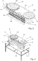
- Figures 3 and 4 show schematic, three-dimensional views of a linear transfer device 30 according to an embodiment, wherein the Figure 4 in addition to the transport components of the Figure 3 shows further assemblies for the transfer of the containers, such as a drive and a table for mounting the transfer device 30.
- the transfer device 30 is used to transport containers 2, the transport being linear, i.e. straight, at least in sections.
- PET bottles each with a bottle neck and a neck ring
- the container 2 there being no restriction in this regard.
- Other container shapes and materials are possible as long as the container 2 differs from the linear one Transfer device 30 are transportable.
- the containers 2 are preferably bottles equipped with a neck ring or bottles with an alternative suitable mouth structure which enables the containers 2 to be transported in a hanging manner by reaching under or supporting the mouth structure.
- the transfer device 30 has a rail system 31 which is set up to guide the containers 2 along an at least partially linear trajectory.
- the rail system 31 can also include one or more curved sections 31b, for example in order to support the transfer from and / or to a rotary machine.
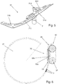
- the rail system 31 is in the Figure 5 shown as a separate assembly.
- the rail system 31 here comprises, for example, an outer rail 31c, which is preferably connected in the curved section 31b to sets of the closing device 40.
- an inner rail 31d is provided in the linear section 31a, so that a gap 31e is formed between the inner rail 31d and the outer rail 31c, in which the bottle neck of the container 2 is guided.
- Figure 6 shows a top view of the linear transfer device 30 with a schematically illustrated inlet, for example of a filling device 20.
- the container 2 leaves the filling device 20 and is picked up by the rail system 31 below the neck ring.
- the rail system guides the container 2 in a straight line in the linear section 31a.
- the rail system 31 is preferably connected directly to sets of the closing device 40, as a result of which the closing device 40 can receive and close the container 2 without interruption and trouble-free.
- the transfer device 30 further comprises conveying means which are set up to propel the containers 2 along the trajectory predetermined by the rail system 31 and to stabilize the containers 2 during transport.
- the conveying means comprise two drive systems, a belt system 32 and a twin screw system 33.
- the belt system 32 has two rotating disks 32a, 32b and a belt 32c, which is wound or placed around the disks 32a, 32b and is driven in a revolving manner by them.
- One of the two disks 32a can already function as a rotary device 41 of the closing device 40.
- components of the closing device 40 and the transfer device 30 can be used together synergistically, here for example the disk 32a and the circumferential belt 32c.
- the belt 32c comprises a plurality of pushing elements 32d which are set up to push or push the containers 2, preferably in the region of the container mouth, and thus to convey them along the rail system 31.
- the area of the mouth also includes an optionally present neck ring which is formed below an optionally present thread of the container 2.
- the pushing elements 32d have a suitable shape, for example with corresponding recesses which enable the containers 2 to be gripped reliably.
- the thrust elements 32d are curved metal sheets, each with a recess for a form fit with a corresponding bottle neck, which are, for example, riveted to the band 32c.
- One or both disks 32a, 32b are driven via an actuator or several synchronized actuators, which are not shown in detail in the figures.
- One or more electric motors are preferably used.
- the disks 32a, 32b sit on corresponding shafts 32e, 32f, preferably star columns, via which the torque is transmitted to the disks 32a, 32b.
- the power transmission from the disks 32a, 32b to the belt 32c can take place in various ways, for example solely via a belt drive-like friction connection, a force fit and / or form fit.
- the partial view of the Figure 8 shows a preferred way of power transmission, which is achieved here by a form fit.
- the drive disk 32b is equipped with hemispherical projections 32g which are arranged at a regular angular spacing on the outer circumference of the disk 32b.
- the projections 32g cooperate with corresponding holes or recesses 32h in the band 32c, so that a reliable force transmission can be achieved by positive locking.
- the recesses 32h snap into the projections 32g, whereby a self-centering effect is also achieved.
- the position of the band 32c and its pushing elements 32d relative to the disks 32a, 32b can be precisely maintained.
- the division is also kept exactly, which is particularly advantageous when the belt system 32 is to be synchronized with other machine components, for example the twin-screw system 33.
- the projections 32g and recesses 32h can also be designed in a different way and / or interchanged with regard to the belt 32c and disk 32b, as long as they have a shape that is complementary to one another, so that a form fit between the two is possible and when the belt system 32 is operated as intended intermittently, ie when the band 32c is in contact with the corresponding disk 32a, 32b.
- the basic principle of the belt system 32 is similar to a belt drive, the belt 32c preferably being a steel belt.
- a steel belt has a high force / weight ratio and, depending on the alloy, is highly resistant to chemicals, moisture and corrosion. Furthermore, good durability is guaranteed even at high temperatures and under vacuum. Lubrication is not required for the operation of the steel belt, which results in overall low maintenance and high reliability.
- a steel belt can be operated with comparatively little vibration and is not or only insignificantly expandable. As a result, a high degree of precision, precise application and reproducibility can be achieved.
- the steel strip has good thermal and electrical conductivity and is not subject to any static charge. With the use of a steel belt, a high degree of hygiene can also be achieved, which makes it particularly suitable for clean room applications, for example when filling foodstuffs or pharmaceuticals.
- the Figures 3, 4 , 6th , 7 and 8 show the belt system 32 with two disks 32a and 32b.
- one or more further deflecting disks can optionally be provided.
- another means of transport such as a chain, a wire or a belt, can also be used instead of the belt 32c.
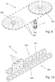
- the Figure 9 shows such an alternative belt system 32 'which, instead of a belt 32c made from a strip-shaped material, uses a rope 32c', preferably steel rope or wire.
- the pushing elements 32d ' are attached to the wire or cable 32c', preferably via two points: a fixed connection and a loose connection.
- the cable 32c ' rotates driven by the pulleys 32a', 32b ', with a form fit between the cable 32c' and the pulleys 32a ', 32b' in order to ensure a safe and slip-free power transmission.
- the form fit can be realized at the connection points of the thrust elements 32d '.
- an elastomer can be introduced into the cable guide of the drive pulley 32a 'and / or 32b' in order to improve the power transmission.
- the pushing elements 32d ' are held in the horizontal position by the rail system 31.
- the containers 2 are removed from the filling device 20 and pushed along the rail system 31 by means of the pushing elements 32b, 32b '.
- the other side of the belt system 32 is integrated in the closing device 40. If the container 2 has been picked up by the closing device 40, the corresponding thrust element 32b, 32b 'only moves passively and returns to the starting point of the cycle.
- the linear transfer device 30 has a further drive system, which is preferably designed as a twin screw system 33 here.
- twin screw system 33 comprises a first screw 33a and a second screw 33b, which are arranged parallel to one another and are each rotatable about their own axis.
- the screws 33a, 33b each have a transport thread 33c, 33d, which is a spiral recess for partially receiving the container 2.
- the screws 33a, 33b encompass or grip the container 2 at the belly section, as shown in FIG Figure 10 emerges.
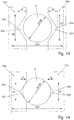
- the transport threads 33c, 33d particularly preferably have a V-shaped cross section, seen in a section parallel to the axial direction of the screws 33a, 33b, as can be seen from FIG Figure 11 emerges.
- the Figure 11 contains some example dimensions, given in mm, for example for the diameter of the container 2 and the distance between the two screws 33a, 33b from one another.
- the dimensions are only exemplary; however, it helps from a comparison with the Figure 12 , in which a container with a smaller diameter (compared to the Figure 11 ) is used, it can be seen that the V-shape of the transport thread 33c, 33d enables the transport of different container sizes, in particular different bottle diameters. For this purpose, only the central axis distance of the screws 33a, 33b has to be changed.
- the threaded cutout 33e at the container inlet can be so large or deep that the container 2 is initially not touched by the screws 33a, 33b.
- the "thread cutout” here denotes the recess depth of the transport thread 33c, 33d, which, with a constant V angle, also determines the axial length of the thread recess on the outer circumference of the worm 33a, 33b.
- the thread cutout 33e becomes gradually smaller until the desired or required cutout is reached and the container 2 is sufficiently encompassed or encased so that the screws 33a, 33b can drive the container 2 forward by positive locking.
- This special thread inlet for gently receiving the container 2 is based on a comparison of FIG Figures 13 and 14 emerged.
- the change in the thread cutout 33e seen in the axial direction of the worm 33b is shown in FIG Figure 15 shown.
- the screw 33b facing away from an inlet radius can be made longer, as is particularly clear from FIG Figure 16 emerges.
- the transport threads 33c, 33d of the screws 33a, 33b encompass the belly of the container 2 initially without contact and then gradually narrower, whereby the container 2 is passed and stabilized in a gentle way. Any pendulum movements are effectively prevented by the twin screw system 33.
- the container 2 is advanced in the transport direction by the twin screw system 33.
- the worms 33a, 33b are rotated in opposite directions and synchronously about their axes.
- the screws 33a, 33b push the container 2 due to the V-shape of the transport threads 33c, 33d over only two points of application along the linear trajectory of the transfer device 30, whereby the container 2 is treated particularly gently.
- the twin screw system 33 is also synchronized with the belt system 32 in order to ensure that the containers 2 are transported evenly and safely. After a container 2 has covered the transport path of the twin screw system 33, it is picked up by the closing device 40.
- a complete transport process of a container 2 by means of the linear transfer device 30 can proceed as follows: A container 2 filled with a filling product by the filling device 20 approaches an area for transfer to the transfer device 30.
- the screws 33a, 33b of the twin-screw system 33 encompass the container 2 initially contactless.
- a clamp of the filling device 20 for holding and transporting the container 2 opens.
- the The container mouth is received by the rail system 31, and the screws 33a, 33b are now fully engaged with the container 2.
- a push element 32d, 32d ' approaches the mouth area of the container, in particular a neck ring, if present.
- the container is pushed along the rail system 31 by a total of three force application points, two screws 33a, 33b and one push element 32d, 32d '.
- the container is transferred to the closing device 40, for example by the container falling from the rail system 31 into a spike plate of a container holder of the closing device 40.
- the pusher element 32d, 32d ' releases the engagement and the container 2 leaves the twin screw system 33.
Landscapes
- Engineering & Computer Science (AREA)
- Mechanical Engineering (AREA)
- Filling Of Jars Or Cans And Processes For Cleaning And Sealing Jars (AREA)
- Specific Conveyance Elements (AREA)
Applications Claiming Priority (1)
| Application Number | Priority Date | Filing Date | Title |
|---|---|---|---|
| DE102020111119.3A DE102020111119A1 (de) | 2020-04-23 | 2020-04-23 | Vorrichtung zum linearen Transportieren von Behältern |
Publications (1)
| Publication Number | Publication Date |
|---|---|
| EP3901084A1 true EP3901084A1 (fr) | 2021-10-27 |
Family
ID=75659960
Family Applications (1)
| Application Number | Title | Priority Date | Filing Date |
|---|---|---|---|
| EP21170255.0A Pending EP3901084A1 (fr) | 2020-04-23 | 2021-04-23 | Dispositif de transport linéaire des récipients |
Country Status (3)
| Country | Link |
|---|---|
| EP (1) | EP3901084A1 (fr) |
| CN (1) | CN216426706U (fr) |
| DE (1) | DE102020111119A1 (fr) |
Cited By (1)
| Publication number | Priority date | Publication date | Assignee | Title |
|---|---|---|---|---|
| WO2023110057A1 (fr) * | 2021-12-13 | 2023-06-22 | Ferrum Packaging Ag | Système d'alimentation de récipient pour transporter un récipient, et dispositif de traitement et procédé de transport d'un récipient |
Families Citing this family (1)
| Publication number | Priority date | Publication date | Assignee | Title |
|---|---|---|---|---|
| DE102022112576B3 (de) | 2022-05-19 | 2023-06-29 | Leibinger Gmbh | Vorrichtung zum Transportieren von Behältnissen |
Citations (5)
| Publication number | Priority date | Publication date | Assignee | Title |
|---|---|---|---|---|
| US2857037A (en) * | 1956-04-09 | 1958-10-21 | Crown Cork & Seal Co | Container feeding mechanism |
| US3565235A (en) * | 1968-09-27 | 1971-02-23 | Anchor Hocking Corp | Conveyor transfer apparatus |
| US3780847A (en) * | 1972-01-13 | 1973-12-25 | Sybron Corp | Rotary filling machine |
| DE102016110722A1 (de) | 2016-06-10 | 2017-12-14 | Krones Ag | Vorrichtung und Verfahren zum Befüllen von Behältern mit einem Füllprodukt |
| DE102017130036A1 (de) | 2017-12-14 | 2019-06-19 | Krones Ag | Vorrichtung zum Transportieren eines Behälters |
Family Cites Families (6)
| Publication number | Priority date | Publication date | Assignee | Title |
|---|---|---|---|---|
| US3004650A (en) | 1959-05-18 | 1961-10-17 | Meyer Geo J Mfg Co | Article orienting apparatus |
| DE2919488C2 (de) | 1979-05-15 | 1984-12-06 | Kronseder, Hermann, 8404 Wörth | Vorrichtung zum Vereinzeln von im wesentlichen rechteckigen oder quadratischen Gefäßen, insbesondere in Gefäßbehandlungsmaschinen |
| CH687248A5 (de) | 1991-10-30 | 1996-10-31 | Mitsubishi Heavy Ind Ltd | Dosenzufuehreinrichtung fuer eine Dosenverschliessmaschine. |
| IT1263442B (it) | 1993-06-23 | 1996-08-05 | Marchesini Group Spa | Metodo per il controllo in continuo del peso di flaconi e apparecchiature per attuare tale metodo. |
| DE29515052U1 (de) | 1995-09-20 | 1995-11-23 | KRONES AG, 93073 Neutraubling | Inspektionsmaschine für Flaschen o.dgl. |
| ATE390383T1 (de) | 2003-07-30 | 2008-04-15 | Graham Packaging Co | Behälterhandhabungssystem |
-
2020
- 2020-04-23 DE DE102020111119.3A patent/DE102020111119A1/de active Pending
-
2021
- 2021-04-21 CN CN202120821802.4U patent/CN216426706U/zh active Active
- 2021-04-23 EP EP21170255.0A patent/EP3901084A1/fr active Pending
Patent Citations (5)
| Publication number | Priority date | Publication date | Assignee | Title |
|---|---|---|---|---|
| US2857037A (en) * | 1956-04-09 | 1958-10-21 | Crown Cork & Seal Co | Container feeding mechanism |
| US3565235A (en) * | 1968-09-27 | 1971-02-23 | Anchor Hocking Corp | Conveyor transfer apparatus |
| US3780847A (en) * | 1972-01-13 | 1973-12-25 | Sybron Corp | Rotary filling machine |
| DE102016110722A1 (de) | 2016-06-10 | 2017-12-14 | Krones Ag | Vorrichtung und Verfahren zum Befüllen von Behältern mit einem Füllprodukt |
| DE102017130036A1 (de) | 2017-12-14 | 2019-06-19 | Krones Ag | Vorrichtung zum Transportieren eines Behälters |
Cited By (3)
| Publication number | Priority date | Publication date | Assignee | Title |
|---|---|---|---|---|
| WO2023110057A1 (fr) * | 2021-12-13 | 2023-06-22 | Ferrum Packaging Ag | Système d'alimentation de récipient pour transporter un récipient, et dispositif de traitement et procédé de transport d'un récipient |
| US20250026625A1 (en) * | 2021-12-13 | 2025-01-23 | Ferrum Packaging Ag | Container feeding system for transporting container, as well as processing device and method for transporting container |
| US12509340B2 (en) * | 2021-12-13 | 2025-12-30 | Ferrum Packaging Ag | Container feeding system for transporting container, as well as processing device and method for transporting container |
Also Published As
| Publication number | Publication date |
|---|---|
| DE102020111119A1 (de) | 2021-10-28 |
| CN216426706U (zh) | 2022-05-03 |
Similar Documents
| Publication | Publication Date | Title |
|---|---|---|
| EP3094590B1 (fr) | Machine de traitement de récipients pour traiter des récipients | |
| EP0414081B1 (fr) | Procédé et dispositif pour remplir et fermer des récipients | |
| EP1520813B1 (fr) | Machine de traitement de récipients | |
| DE102016106378A1 (de) | Vorrichtung zum Behandeln von Behältern sowie Getränkeabfüllanlage | |
| EP2826718B1 (fr) | Dispositif de transport pour une machine de traitement de récipients | |
| EP2269923A2 (fr) | Dispositif de transport de récipients vers une unité de transformation | |
| EP3901084A1 (fr) | Dispositif de transport linéaire des récipients | |
| EP3090969B1 (fr) | Dispositif d'amortissement de fermetures de recipients | |
| EP2370330B1 (fr) | Système d'alimentation en récipients | |
| DE60219978T2 (de) | Vorrichtung zum Anordnen von Behältern, insbesondere von Flaschen, in gleichen Abständen | |
| DE102015115729B4 (de) | Behältertransporteur | |
| DE1084640B (de) | Vorrichtung zum Aufteilen von auf einem ersten Foerderer angelieferten Behaeltern auf zwei Weiterfoerderer | |
| DE1602476A1 (de) | Einrichtung zum Handhaben von Behaeltern | |
| DE1965394A1 (de) | Behaelterueberfuehrungsvorrichtung | |
| WO2023110057A1 (fr) | Système d'alimentation de récipient pour transporter un récipient, et dispositif de traitement et procédé de transport d'un récipient | |
| DE102015201852B4 (de) | Vorrichtung und Verfahren zum Geschwindigkeitsabbau eines Behälterstroms in einer Behälterbehandlungsanlage | |
| EP3838813B1 (fr) | Dispositif de traitement des récipients avec un dispositif d'alimentation ou d'évacuation d'un récipient | |
| EP0256550B1 (fr) | Table de chargement pour appareils de manutention des récipients | |
| EP2882651B1 (fr) | Procede et dispositif pour alimenter espacés et alignés éléments verseurs ayant un rebord | |
| DE2808042A1 (de) | Vorrichtung zur bearbeitung, insbesondere zum fuellen und verschliessen von ampullen o.dgl. | |
| EP4310028A1 (fr) | Système d'alimentation de récipients pour le transport de récipients | |
| EP4169871B1 (fr) | Dispositif d'alimentation de bouchons à un dispositif de fermeture dans une installation de remplissage de boissons | |
| AT526279B1 (de) | Verfahren zum Fördern und Orientieren von Ausgießelementen mit Verschluss und Fördervorrichtung | |
| WO2019057304A1 (fr) | Convertisseur de pas à ciseaux | |
| DE102015110765A1 (de) | Vorrichtung zum Transport eines Behälters |
Legal Events
| Date | Code | Title | Description |
|---|---|---|---|
| PUAI | Public reference made under article 153(3) epc to a published international application that has entered the european phase |
Free format text: ORIGINAL CODE: 0009012 |
|
| STAA | Information on the status of an ep patent application or granted ep patent |
Free format text: STATUS: THE APPLICATION HAS BEEN PUBLISHED |
|
| AK | Designated contracting states |
Kind code of ref document: A1 Designated state(s): AL AT BE BG CH CY CZ DE DK EE ES FI FR GB GR HR HU IE IS IT LI LT LU LV MC MK MT NL NO PL PT RO RS SE SI SK SM TR |
|
| B565 | Issuance of search results under rule 164(2) epc |
Effective date: 20210924 |
|
| STAA | Information on the status of an ep patent application or granted ep patent |
Free format text: STATUS: REQUEST FOR EXAMINATION WAS MADE |
|
| 17P | Request for examination filed |
Effective date: 20220328 |
|
| RBV | Designated contracting states (corrected) |
Designated state(s): AL AT BE BG CH CY CZ DE DK EE ES FI FR GB GR HR HU IE IS IT LI LT LU LV MC MK MT NL NO PL PT RO RS SE SI SK SM TR |
|
| P01 | Opt-out of the competence of the unified patent court (upc) registered |
Effective date: 20230523 |