EP3901094B1 - Couche d'aérogel et sa méthode de fabrication - Google Patents
Couche d'aérogel et sa méthode de fabrication Download PDFInfo
- Publication number
- EP3901094B1 EP3901094B1 EP20860342.3A EP20860342A EP3901094B1 EP 3901094 B1 EP3901094 B1 EP 3901094B1 EP 20860342 A EP20860342 A EP 20860342A EP 3901094 B1 EP3901094 B1 EP 3901094B1
- Authority
- EP
- European Patent Office
- Prior art keywords
- blanket
- substrate
- aerogel
- sol
- gelation
- Prior art date
- Legal status (The legal status is an assumption and is not a legal conclusion. Google has not performed a legal analysis and makes no representation as to the accuracy of the status listed.)
- Active
Links
Images
Classifications
-
- C—CHEMISTRY; METALLURGY
- C04—CEMENTS; CONCRETE; ARTIFICIAL STONE; CERAMICS; REFRACTORIES
- C04B—LIME, MAGNESIA; SLAG; CEMENTS; COMPOSITIONS THEREOF, e.g. MORTARS, CONCRETE OR LIKE BUILDING MATERIALS; ARTIFICIAL STONE; CERAMICS; REFRACTORIES; TREATMENT OF NATURAL STONE
- C04B30/00—Compositions for artificial stone, not containing binders
- C04B30/02—Compositions for artificial stone, not containing binders containing fibrous materials
-
- B—PERFORMING OPERATIONS; TRANSPORTING
- B01—PHYSICAL OR CHEMICAL PROCESSES OR APPARATUS IN GENERAL
- B01J—CHEMICAL OR PHYSICAL PROCESSES, e.g. CATALYSIS OR COLLOID CHEMISTRY; THEIR RELEVANT APPARATUS
- B01J13/00—Colloid chemistry, e.g. the production of colloidal materials or their solutions, not otherwise provided for; Making microcapsules or microballoons
- B01J13/0091—Preparation of aerogels, e.g. xerogels
-
- B—PERFORMING OPERATIONS; TRANSPORTING
- B01—PHYSICAL OR CHEMICAL PROCESSES OR APPARATUS IN GENERAL
- B01J—CHEMICAL OR PHYSICAL PROCESSES, e.g. CATALYSIS OR COLLOID CHEMISTRY; THEIR RELEVANT APPARATUS
- B01J3/00—Processes of utilising sub-atmospheric or super-atmospheric pressure to effect chemical or physical change of matter; Apparatus therefor
- B01J3/008—Processes carried out under supercritical conditions
-
- C—CHEMISTRY; METALLURGY
- C01—INORGANIC CHEMISTRY
- C01B—NON-METALLIC ELEMENTS; COMPOUNDS THEREOF; METALLOIDS OR COMPOUNDS THEREOF NOT COVERED BY SUBCLASS C01C
- C01B33/00—Silicon; Compounds thereof
- C01B33/113—Silicon oxides; Hydrates thereof
- C01B33/12—Silica; Hydrates thereof, e.g. lepidoic silicic acid
- C01B33/14—Colloidal silica, e.g. dispersions, gels, sols
- C01B33/145—Preparation of hydroorganosols, organosols or dispersions in an organic medium
-
- C—CHEMISTRY; METALLURGY
- C01—INORGANIC CHEMISTRY
- C01B—NON-METALLIC ELEMENTS; COMPOUNDS THEREOF; METALLOIDS OR COMPOUNDS THEREOF NOT COVERED BY SUBCLASS C01C
- C01B33/00—Silicon; Compounds thereof
- C01B33/113—Silicon oxides; Hydrates thereof
- C01B33/12—Silica; Hydrates thereof, e.g. lepidoic silicic acid
- C01B33/14—Colloidal silica, e.g. dispersions, gels, sols
- C01B33/155—Preparation of hydroorganogels or organogels
-
- C—CHEMISTRY; METALLURGY
- C01—INORGANIC CHEMISTRY
- C01B—NON-METALLIC ELEMENTS; COMPOUNDS THEREOF; METALLOIDS OR COMPOUNDS THEREOF NOT COVERED BY SUBCLASS C01C
- C01B33/00—Silicon; Compounds thereof
- C01B33/113—Silicon oxides; Hydrates thereof
- C01B33/12—Silica; Hydrates thereof, e.g. lepidoic silicic acid
- C01B33/14—Colloidal silica, e.g. dispersions, gels, sols
- C01B33/157—After-treatment of gels
- C01B33/158—Purification; Drying; Dehydrating
-
- C—CHEMISTRY; METALLURGY
- C01—INORGANIC CHEMISTRY
- C01B—NON-METALLIC ELEMENTS; COMPOUNDS THEREOF; METALLOIDS OR COMPOUNDS THEREOF NOT COVERED BY SUBCLASS C01C
- C01B33/00—Silicon; Compounds thereof
- C01B33/113—Silicon oxides; Hydrates thereof
- C01B33/12—Silica; Hydrates thereof, e.g. lepidoic silicic acid
- C01B33/14—Colloidal silica, e.g. dispersions, gels, sols
- C01B33/157—After-treatment of gels
- C01B33/158—Purification; Drying; Dehydrating
- C01B33/1585—Dehydration into aerogels
-
- C—CHEMISTRY; METALLURGY
- C01—INORGANIC CHEMISTRY
- C01B—NON-METALLIC ELEMENTS; COMPOUNDS THEREOF; METALLOIDS OR COMPOUNDS THEREOF NOT COVERED BY SUBCLASS C01C
- C01B33/00—Silicon; Compounds thereof
- C01B33/113—Silicon oxides; Hydrates thereof
- C01B33/12—Silica; Hydrates thereof, e.g. lepidoic silicic acid
- C01B33/14—Colloidal silica, e.g. dispersions, gels, sols
- C01B33/157—After-treatment of gels
- C01B33/159—Coating or hydrophobisation
-
- C—CHEMISTRY; METALLURGY
- C04—CEMENTS; CONCRETE; ARTIFICIAL STONE; CERAMICS; REFRACTORIES
- C04B—LIME, MAGNESIA; SLAG; CEMENTS; COMPOSITIONS THEREOF, e.g. MORTARS, CONCRETE OR LIKE BUILDING MATERIALS; ARTIFICIAL STONE; CERAMICS; REFRACTORIES; TREATMENT OF NATURAL STONE
- C04B14/00—Use of inorganic materials as fillers, e.g. pigments, for mortars, concrete or artificial stone; Treatment of inorganic materials specially adapted to enhance their filling properties in mortars, concrete or artificial stone
- C04B14/02—Granular materials, e.g. microballoons
- C04B14/04—Silica-rich materials; Silicates
- C04B14/06—Quartz; Sand
- C04B14/064—Silica aerogel
-
- C—CHEMISTRY; METALLURGY
- C01—INORGANIC CHEMISTRY
- C01P—INDEXING SCHEME RELATING TO STRUCTURAL AND PHYSICAL ASPECTS OF SOLID INORGANIC COMPOUNDS
- C01P2006/00—Physical properties of inorganic compounds
- C01P2006/32—Thermal properties
-
- C—CHEMISTRY; METALLURGY
- C04—CEMENTS; CONCRETE; ARTIFICIAL STONE; CERAMICS; REFRACTORIES
- C04B—LIME, MAGNESIA; SLAG; CEMENTS; COMPOSITIONS THEREOF, e.g. MORTARS, CONCRETE OR LIKE BUILDING MATERIALS; ARTIFICIAL STONE; CERAMICS; REFRACTORIES; TREATMENT OF NATURAL STONE
- C04B2201/00—Mortars, concrete or artificial stone characterised by specific physical values
- C04B2201/30—Mortars, concrete or artificial stone characterised by specific physical values for heat transfer properties such as thermal insulation values, e.g. R-values
- C04B2201/32—Mortars, concrete or artificial stone characterised by specific physical values for heat transfer properties such as thermal insulation values, e.g. R-values for the thermal conductivity, e.g. K-factors
-
- Y—GENERAL TAGGING OF NEW TECHNOLOGICAL DEVELOPMENTS; GENERAL TAGGING OF CROSS-SECTIONAL TECHNOLOGIES SPANNING OVER SEVERAL SECTIONS OF THE IPC; TECHNICAL SUBJECTS COVERED BY FORMER USPC CROSS-REFERENCE ART COLLECTIONS [XRACs] AND DIGESTS
- Y02—TECHNOLOGIES OR APPLICATIONS FOR MITIGATION OR ADAPTATION AGAINST CLIMATE CHANGE
- Y02A—TECHNOLOGIES FOR ADAPTATION TO CLIMATE CHANGE
- Y02A20/00—Water conservation; Efficient water supply; Efficient water use
- Y02A20/124—Water desalination
-
- Y—GENERAL TAGGING OF NEW TECHNOLOGICAL DEVELOPMENTS; GENERAL TAGGING OF CROSS-SECTIONAL TECHNOLOGIES SPANNING OVER SEVERAL SECTIONS OF THE IPC; TECHNICAL SUBJECTS COVERED BY FORMER USPC CROSS-REFERENCE ART COLLECTIONS [XRACs] AND DIGESTS
- Y02—TECHNOLOGIES OR APPLICATIONS FOR MITIGATION OR ADAPTATION AGAINST CLIMATE CHANGE
- Y02E—REDUCTION OF GREENHOUSE GAS [GHG] EMISSIONS, RELATED TO ENERGY GENERATION, TRANSMISSION OR DISTRIBUTION
- Y02E60/00—Enabling technologies; Technologies with a potential or indirect contribution to GHG emissions mitigation
- Y02E60/13—Energy storage using capacitors
Definitions
- the present invention relates to a method for manufacturing an aerogel blanket including a step of gelation while rotating a substrate for a blanket into which a sol is impregnated and to a high thermal insulation aerogel blanket manufactured by the method.
- An aerogel is a super-porous, high specific surface area ( ⁇ 500 m 2 /g) material having a porosity of about 90-99.9% and a pore size in the range of 1-100 nm, and is a material having excellent properties of ultra-light weight, super thermal insulation, ultra-low dielectric, and the like. Accordingly, research on the development of aerogel materials as well as research on the practical use thereof as transparent insulation materials, environmentally friendly high temperature insulation materials, ultra-low dielectric thin films for highly integrated devices, catalysts and catalyst carriers, electrodes for super capacitors, and electrode materials for seawater desalination have been actively conducted.
- the aerogel has super-insulation properties exhibiting a thermal conductivity of 0.300 W/m ⁇ K or less, which is lower than that of a conventional organic thermal insulation material such as Styrofoam, and that fire vulnerability and the generation of harmful gases in case of occurrence of fire which are fatal weaknesses of the organic thermal insulation material can be solved.
- the aerogel is produced by preparing a hydrogel from a precursor material, and removing a liquid component inside the hydrogel without destroying a microstructure.
- An aerogel may be typically classified into three types, i.e., powder, granule, and monolith, and the silica aerogel is generally produced in the form of powder.
- the above powder-type silica aerogel may be made into a composite with fibers and be commercialized in the form of an aerogel blanket or an aerogel sheet.
- Such an aerogel blanket and an aerogel sheet may be bent, folded, or cut in any size or shape due to the flexibility thereof. Therefore, the powder-type silica aerogel may be applied not only to industrial applications such as thermal insulation panels for LNG carriers, industrial insulation materials, spacesuits, transportation, vehicles, and insulation materials for electric power production, but also to household goods such as jackets and sports shoes.
- an aerogel is used in fireproof doors as well as roofs and floors in housing such as an apartment, there is a great effect in fire prevention.
- an aerogel blanket in the present specification is a concept referring to a material in which an aerogel is impregnated on a substrate for a blanket such as a fiber, and a method for manufacturing the aerogel blanket is divided into a gel casting method and a method for preparing aerogel powder or granules and then depositing the same on a substrate for a blanket using a binder.
- the method is capable of simplifying manufacturing equipment while increasing manufacturing process efficiency, and which may be commercialized in a mass production process since manufacturing time is not greatly affected by the thickness and the length of the aerogel blanket.
- Patent Document 1 KR10-2012-0070948A
- EP 3 284 720 A1 discloses a method for obtaining silica aerogel blankets comprising the steps: mixing silica precursor solution and catalyst solution so as to obtain silica sol, injecting the silica sol in a rotating tray so that a gelation step is conducted and the aerogel is formed on fiber sheets which are then moved out of the tray and the final product is recovered.
- the catalyst solution comprises TEOS as a silica precursor.
- KR 2017 0086 831 A discloses a method for manufacturing an aerogel sheet including a step of immersing a blanket in an impregnation vessel in which silica sol is stored to impregnate the silica sol, and a step of injecting a gelling catalyst to a surface of the blanket in which the silica sol is impregnated to gelate the silica sol.
- WO 2019/039841 A1 discloses a manufacturing method for a silica aerogel blanket and a manufacturing apparatus therefore.
- US 2019/002356 A1 discloses a method for producing silica aerogel in sheet form including in-situ production of titanium dioxide nanoparticles in very minor concentrations during gelation of silica precursor, with nanoporous surface area more than 300 m 2 /g and acting as an infrared reflecting agent.
- EP 3 375 757 A1 discloses a silica aerogel blanket for ultra-high temperature, the method of its preparation including a step of heat treatment after producing a hydrophobic silica aerogel blanket so as to remove volatile organic compound.
- KR 100 710 887 B1 discloses a silica aerogel blanket having a thermal conductivity ranging from 18 to 20 mw/mk.
- an aspect of the present invention provides a method for manufacturing an aerogel blanket, the method is capable of greatly reducing manufacturing time by performing gelation while rotating a substrate for a blanket into which a catalyzed sol is impregnated during a gelation process and simplifying manufacturing equipment by not allowing the thickness and length of the aerogel blanket to affect the manufacturing time.
- Another aspect of the present invention provides a method for manufacturing an aerogel blanket, the method is capable of allowing an aerogel to be uniformly formed in a substrate for a blanket by rotating the substrate for a blanket into which a sol is impregnated, thereby further improving the uniformity of the aerogel formed in the substrate for a blanket, and accordingly exhibiting uniform thermal conductivity in the entire aerogel blanket, and improving the thermal conductivity of the aerogel blanket.
- Another aspect of the present invention is to provide a high thermal insulation aerogel blanket manufactured by the method for manufacturing an aerogel blanket.
- a method for manufacturing an aerogel blanket including 1) introducing a catalyzed sol and a substrate for a blanket into a reaction vessel to impregnate the catalyzed sol into the substrate for a blanket, and 2) rotating the substrate for a blanket into which the catalyzed sol is impregnated to perform gelation.
- the substrate for a blanket is introduced into the reaction vessel in the state of being wound on a bobbin, and the bobbin is rotated to rotate the substrate for a blanket into which the catalyzed sol is impregnated.
- an aerogel blanket in which the deviation between the highest value of the thermal conductivity of the aerogel blanket and the lowest value of the thermal conductivity thereof is 5.0 mW/mK or less.
- the invention also provides an aerogel blanket according to claim 14. Further embodiments are disclosed in the dependent claim 15.
- a manufacturing method of the present invention may greatly reduce manufacturing time by performing gelation by rotating a substrate for a blanket into which a catalyzed sol is impregnated, and also simplify manufacturing equipment by not allowing the thickness and length of an aerogel blanket to affect the manufacturing time.
- the substrate for a blanket is thin and long, the above-described effect of the present invention is further maximized, in which case it is particularly advantageous in greatly increasing productivity.
- an aerogel may be uniformly formed in the substrate for a blanket to further improve the uniformity of the aerogel formed in the substrate for a blanket.
- an aerogel blanket according to an embodiment of the present invention has uniformly formed aerogel, so that uniform thermal conductivity may be exhibited in the entire aerogel blanket, and the deviation between the highest value of the thermal conductivity of the aerogel blanket and the lowest value of the thermal conductivity thereof is small, so that the overall thermal conductivity of the aerogel blanket may be greatly improved, and thus, the aerogel blanket may be easily used in industrial fields in which high thermal insulation is required.
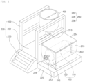
- FIG. 1 is a perspective view showing an aerogel blanket manufacturing device according to an embodiment of the present invention.
- a method for manufacturing an aerogel blanket according to an embodiment of the present invention is characterized by including 1) introducing a catalyzed sol and a substrate for a blanket into a reaction vessel to impregnate the catalyzed sol into the substrate for a blanket, and 2) rotating the substrate for a blanket into which the catalyzed sol is impregnated to perform gelation.
- Step 1) is a step of preparation for forming an aerogel blanket, which is to impregnate a catalyzed sol into a substrate for a blanket, wherein a catalyzed sol may be prepared and then the prepared catalyzed sol and a substrate for a blanket may be introduced into a reaction vessel to impregnate the catalyzed sol into the substrate for a blanket.
- the term "impregnation" used in the present invention may be achieved by introducing a catalyzed sol having fluidity to a substrate for a blanket, and may indicate that the catalyzed sol is penetrated into pores inside the substrate for a blanket.
- Step 1) as long as a substrate for a blanket and a catalyzed sol are introduced in a reaction vessel, the introduction order thereof is not particularly limited.
- the introduction may be performed by any one method among a method for introducing a substrate for a blanket into a reaction vessel and then introducing a catalyzed sol, a method for introducing a catalyzed sol into a reaction vessel and then introducing a substrate for a blanket, and a method for introducing a substrate for a blanket while introducing a catalyzed sol into a reaction vessel.
- the method for introducing a substrate for a blanket and then introducing a catalyzed sol may be more desirable. Specifically, when a substrate for a blanket is first introduced, the substrate for a blanket may be rotated when a catalyzed sol is introduced, so that more uniform impregnation may be induced.
- the impregnation may be performed while rotating the substrate for a blanket as described above.
- a catalyzed sol may uniformly come into contact with all surfaces of the substrate for a blanket to induce uniform impregnation, which is more desirable.
- the catalyzed sol may be prepared by mixing a sol and a base catalyst, wherein the base catalyst serves to promote gelation in Step 2) by increasing the pH of the sol.
- the sol is not limited as long as it is a material capable of forming a porous gel by a sol-gel reaction, and specifically, may include an inorganic sol, an organic sol, or a combination thereof.
- the inorganic sol may include zirconia, yttrium oxide, hafnia, alumina, titania, ceria, silica, magnesium oxide, calcium oxide, fluorinated magnesium, fluorinated calcium, and combinations thereof
- the organic sol may be polyacrylate, polyolefin, polystyrene, polyacrylonitrile, polyurethane, polyimide, polyfurfural alcohol, phenol furfuryl alcohol, melamine formaldehyde, resorcinol formaldehyde, cresol formaldehyde, phenol formaldehyde, polyvinyl alcohol dialdehyde, polycyanurate, polyacrylamide, various epoxies, agar, agarose, and combinations thereof.
- sttrium oxide ha
- the sol according to an embodiment of the present invention contains a sol precursor, water, and an organic solvent, and may be prepared by mixing a sol precursor, water, and an organic solvent.
- the catalyzed sol according to an embodiment of the present invention is a catalyzed silica sol
- the catalyzed silica sol may be prepared by mixing a silica sol and a base catalyst, wherein the silica sol may be prepared by mixing a silica precursor, water, and an organic solvent.
- the silica sol may undergo hydrolysis at a low pH to facilitate gelation, and at this time, an acid catalyst may be used to lower a pH.
- a silica precursor which may be used for preparing the silica sol may be an alkoxide-based compound containing silicon, specifically, tetraalkyl silicate such as tetramethyl orthosilicate (TMOS), tetraethyl orthosilicate (TEOS), methyl triethyl orthosilicate, dimethyl diethyl orthosilicate, tetrapropyl orthosilicate, tetraisopropyl orthosilicate, tetrabutyl orthosilicate, tetra secondary butyl orthosilicate, tetra tertiary butyl orthosilicate, tetrahexyl orthosilicate, tetracyclohexyl orthosilicate, and tetradodecyl orthosilicate.
- the silica precursor according to an embodiment of the present invention may more specifically be tetraethyl orthosilicate (TEOS).
- the silica precursor may be used in an amount which allows the content of silica (SiO 2 ) contained in the silica sol to be 3 wt% to 30 wt%. If the content of the silica is less than 3 wt%, the content of a silica aerogel in a blanket to be finally produced is too low to achieve a desired level of thermal insulation effect. If the content of the silica is greater than 30 wt%, due to excessive formation of a silica aerogel, the mechanical properties of a blanket, the flexibility thereof in particular, may deteriorate.
- an organic solvent which may be used for preparing the sol of the present invention
- any material may be used without limitation as long as it has compatibility with a sol precursor and water.
- a polar organic solvent may be used, and more specifically, an alcohol may be used.
- the alcohol may specifically be a monohydric alcohol such as methanol, ethanol, isopropanol, and butanol; or a polyhydric alcohol such as glycerol, ethylene glycol, propylene glycol, diethylene glycol, dipropylene glycol, and sorbitol, and any one thereof or a mixture of two or more thereof may be used.
- the alcohol may be a monohydric alcohol having 1 to 6 carbon atoms such as methanol, ethanol, isopropanol, and butanol.
- the organic solvent as described above may be used in an appropriate amount in consideration of the content of an aerogel to be finally prepared.
- the silica sol according to an embodiment of the present invention may include a silica precursor and water in a molar ratio of 1:4 to 1:1.
- a silica precursor and an organic solvent may be included in a weight ratio of 1:2 to 1:9, and preferably, may be included in a weight ratio of 1:4 to 1:6.
- the production yield of aerogel may further increase, so that there is an effect of improving thermal insulation performance.
- any acid catalyst which may allow a pH to be 3 or less may be used without limitation.
- hydrochloric acid, nitric acid, or sulfuric acid may be used.
- the acid catalyst may be added in an amount which allows the pH of the sol to be 3 or less, and may be added in the form of an aqueous solution dissolved in an aqueous solvent.
- a base catalyst which may be used in the catalyzed sol according to an embodiment of the present invention may be an inorganic base such as sodium hydroxide and potassium hydroxide, or an organic base such as ammonium hydroxide.
- the basic catalyst may be one or more selected from the group consisting of sodium hydroxide
- TMAH tetramethylammonium hydroxide
- TEAH tetraethylammonium hydroxide
- TPAH tetrapropylammonium hydroxide
- TBAH tetrabutylammonium hydroxide
- the base catalyst may be included in an amount which allows the pH of the sol to be 7 to 11. If the pH of the sol is out of the above range, the gelation in Step 2) may not be easily achieved, or a gelation rate may be too low, so that processability may be degraded.
- the base since the base may be precipitated when introduced in a solid phase, it may be preferable that the base is added in the form of a solution diluted by an aqueous solvent or the above-described organic solvent. At this time, the dilution ratio of the base catalyst and the organic solvent, specifically an alcohol, may be 1:4 to 1:100 based on volume.
- the catalyzed sol may further be added with an additive if necessary.
- an additive all known additives which may be added when manufacturing an aerogel may be applied, and for example, an additive such as an opacifying agent, flame retardant, and the like may be used.
- the substrate for a blanket may be introduced in an appropriate form which facilitates the introduction according to the shape of a reaction vessel.
- a substrate for a blanket wound on a bobbin in the form of a roll may be introduced into the reaction vessel to facilitate the rotation in Step 2) to be described later.
- the bobbin can be a shaft capable of rotating the substrate for a blanket, and anything may be applied without limitation as long as it can wind the substrate for a blanket.
- a polygonal cylindrical column preferably a cylindrical column having a size which may fit inside the reaction vessel may be used.
- the bobbin may include a winding rod capable of winding the substrate for a blanket in the form of a roll, and a support plate which supports a side portion of the substrate for a blanket such that the substrate for a blanket wound on the winding rod is not displaced at the time of rotation.
- the winding rod has a number of hollows such that the catalyzed sol may be easily impregnated on the inside of the substrate for a blanket.
- a mesh-type support plate may be used, or the support plate may include a number of hollows. Any material having sufficient strength to support the blanket may be used as the material of the bobbin. Specifically, stainless steel, PE, PP, and Teflon may be used.
- the substrate for a blanket may be wound on the bobbin, and the bobbin may be placed into a reaction vessel and fixed.
- the bobbin may be fixed at any position of the reaction vessel.
- the bobbin may preferably be fixed at a central portion of the reaction vessel.
- the bobbin may be positioned such that the long axis of the bobbin and the long axis of the reaction vessel are parallel to each other.
- the substrate for a blanket according to an embodiment of the present invention may specifically be a porous substrate in terms of improving the thermal insulation properties of an aerogel blanket.
- a porous substrate for a blanket When a porous substrate for a blanket is used, a catalyzed sol is allowed to easily penetrate into the substrate, and thus, forms an aerogel uniformly inside the substrate for a blanket, so that an aerogel blanket manufactured may have excellent thermal insulation properties.
- the substrate for a blanket which may be used according to an embodiment of the present invention may be a film, a sheet, a net, a fiber, a foam, a non-woven body, or a laminate of two or more layers thereof.
- surface roughness may be formed or patterned on the surface thereof.
- the substrate for a blanket may be a fiber capable of further improving thermal insulation performance by including a space or a void through which an aerogel may be easily inserted into the substrate for a blanket.
- the substrate for a blanket may preferably have low thermal conductivity.
- the substrate for a blanket may be polyamide, polybenzimidazole, polyaramid, an acryl resin, a phenol resin, polyester, polyetheretherketone (PEEK), polyolefin (e.g., polyethylene, polypropylene, a copolymer thereof, or the like), cellulose, carbon, cotton, wool, hemp, a non-woven fabric, a glass fiber, ceramic wool, or the like. More specifically, the substrate for a blanket in the present invention may be a glass fiber.
- the reaction vessel may be a reaction vessel for performing gelation, and a vessel in any shape such as a polygon or a cylinder may be used as long as it is a vessel providing a space in which a substrate for a blanket into which a catalyzed sol is impregnated may rotate therein.
- a cylindrical reaction vessel may be preferably used in terms of facilitating the introduction of a substrate for a blanket wound in the form of a roll and the rotation of the substrate for a blanket into which a catalyzed sol is impregnated during a gelation reaction.
- Step 1) above when the catalyzed sol is introduced, in order to improve the bonding of the substrate for a blanket and the catalyzed sol, the substrate for a blanket may be lightly pressed down to achieve sufficient impregnation. Thereafter, the substrate for a blanket may be pressed at a constant pressure to a predetermined thickness to remove excess sol, thereby shortening drying time.
- a drain valve connected to the reaction vessel may be opened to recover remaining sol.
- the catalyzed sol and the substrate for a blanket may each be introduced in an amount, specifically in an amount of 1 to 100% of the internal volume of the reaction vessel, and in terms of shortening the gelation time in Step 2) and uniformly forming an aerogel inside the substrate for a blanket, may be introduced in an amount of 1 to 60% of the volume of the reaction vessel, more specifically 10 to 60%, even more preferably 30 to 60%, respectively.
- the catalyzed sol may be introduced in an amount of 80 to 120%, preferably 90 to 110%, based on the volume of the substrate for a blanket.
- the introduction amount of the substrate for a blanket and the catalyzed sol may satisfy the above introduction ratio therebetween under the conditions satisfying the introduction amount with respect to the reaction vessel.
- the catalyzed sol When a catalyzed sol satisfies the introduction ratio (the introduction amount) with respect to the volume of a substrate for a blanket, the catalyzed sol is more uniformly impregnated on the substrate for a blanket, so that an aerogel blanket to be manufactured may have more uniform physical properties, and since the catalyzed sol may all be impregnated on the substrate for a blanket, it is possible to prevent the loss of raw materials and prevent a problem in which the catalyzed sol is gelled alone.
- the introduction ratio the introduction amount
- Step 2) is to manufacture a wet gel-blanket composite (a wet gel blanket), and may be performed by rotating a substrate for a blanket into which a catalyzed sol is impregnated to be gelled.
- the rotation of the substrate for a blanket into which a catalyzed sol is impregnated may be performed by any method or device as long as the method allows rotation during gelation in a reaction vessel. Specifically, when a substrate for a blanket is introduced and fixed while being wound on a bobbin in Step 1) above, the substrate for a blanket into which a catalyzed sol is impregnated is present in the reaction vessel while being wound on the bobbin, so that the substrate for a blanket into which a catalyzed sol is impregnated may be rotated by rotating the bobbin.
- the gelation may be to form a network structure from a catalyzed sol, wherein the network structure may represent a planar mesh structure in which specific polygons having one or more types of atomic arrangement are linked to each other, or a structure in which specific polyhedrons share their vertices, edges, faces, and the like with each other to form a three-dimensional skeleton structure.
- a gelation reaction may be performed after sealing a reaction vessel into which a catalyzed sol and a substrate for a blanket are introduced.
- rotation may be performed by disposing a long axis in a lateral direction, that is, in a horizontal direction. If the reaction vessel (a main body) is a cylindrical reaction vessel, the cylindrical reaction vessel may be laid down and rotated. That is, the rotating axis of the reaction vessel of the present invention may be horizontal, but is not limited thereto.
- the type of a device for manufacturing an aerogel blanket is not limited as long as it is a device including the reaction vessel (a main body) and capable of rotating the substrate for a blanket into which a catalyzed sol is impregnated present in the reaction vessel.
- Any device known in the art may be used as long as the device is capable of rotating.
- any known device may be used as long as it is capable of fixing the position of a bobbin in a reaction vessel and rotating the bobbin whose position is fixed.
- An example of a device for manufacturing an aerogel blanket which may be applied in the present invention will be described later.
- Step 2) above may be initiated to sequentially perform Step 1) above and Step 2) above.
- Step 2) above may be initiated before Step 1) above is completed.
- Step 2) is performed before the completion of Step 1) above as described above, all of the catalyzed sol may be introduced into the reaction vessel until gelation is completed, specifically before the completion of the gelation.
- the rotation rate in Step 2) above may be applied without limitation as long as it is a rotation rate which allows an aerogel to uniformly form in a blanket.
- gelation may be performed while performing rotation at a rotation rate of 1 rpm to 300 rpm, preferably 5 rpm to 150 rpm, 5 rpm to 100rpm, and more preferably 10 rpm to 30 rpm.
- a sol may be evenly impregnated on a substrate for a blanket, so that an aerogel is more uniformly formed during gelation. Accordingly, it is possible to secure very uniform thermal conductivity throughout an aerogel blanket and there is an advantage in that the safety of a process for manufacturing the aerogel blanket is increased by increasing the stability of a reaction vessel and an apparatus for rotating the reaction vessel.
- a catalyzed sol and a substrate for a blanket are all put into a reaction vessel to be gelled, thereby manufacturing an aerogel blanket, so that unlike a roll-to-roll method, which has been typically applied, a moving element such as a conveyor belt is not separately required, and thus there is an advantage in that a space to be used during the manufacturing may be greatly reduced.
- the gelation is not simultaneously performed on the entire substrate for a blanket, but is sequentially performed over time while continuously supplying the substrate for a blanket and the catalyzed sol, so that there is a problem in that even if a substrate for a blanket having the same thickness and length is used, gelation takes much longer than the gelation process according to an embodiment of the present invention. Specifically, the longer the substrate for a blanket, the more noticeable the problem that gelation process time becomes longer in order to achieve sufficient gelation on the entire substrate for a blanket.
- the gelation of a sol is simultaneously achieved on the entire substrate for a blanket, so that manufacturing time may be significantly reduced.
- the length and thickness of a substrate for a blanket do not affect gelation time, so that even if a long substrate for a blanket is used, manufacturing time may be significantly reduced to maximize process efficiency.
- an aerogel blanket in which an aerogel is more uniformly dispersed may be manufactured, so that the thickness of the manufactured aerogel blanket is the same or very similar to the thickness of a substrate for a blanket, and there is an effect in that thermal insulation properties are excellent.
- the rotation in Step 2) above may be performed by having the rotation axis of the substrate for a blanket in a lateral direction.
- the lateral direction may refer to a direction horizontal to the ground.
- the catalyzed sol or the catalyzed sol impregnated into the substrate for a blanket may be driven in the direction of the ground by gravity.
- uniform impregnation and gelation may be induced by centrifugal force in the direction perpendicular to the rotation axis of the substrate for a blanket substrate, but non-uniform impregnation and gelation may be induced in the direction horizontal to the rotation axis of the substrate for a blanket substrate. Therefore, in order to induce uniform impregnation and gelation by allowing the catalyzed sol to uniformly come into contact with all surfaces of the substrate for a blanket, that is, in both the direction perpendicular to the rotation axis of the substrate for a blanket and the direction horizontal thereto, it may be preferable that the rotation in Step 2) is performed having the rotation axis of the substrate for a blanket in a lateral direction.
- the manufacturing method according to an embodiment of the present invention may perform an aging step as a process for allowing a chemical change to be completely achieved by leaving the wet gel blanket composite to stand at a suitable temperature.
- the aging step may more firmly form the formed network structure, and thus, may enhance the mechanical stability of the aerogel blanket of the present invention.
- the aging step of the present invention is performed by adding a solution in which a basic catalyst such as sodium hydroxide (NaOH), potassium hydroxide (KOH), ammonium hydroxide (NH 4 OH), triethylamine, pyridine, and the like is diluted in an organic solvent at a concentration of 1-10%. Therefore, a Si-O-Si bonding in an aerogel is induced to the maximum to allow the network structure of a silica gel to be more firm, so that there is an effect of facilitating the maintenance of the pore structure in a quick drying process to be performed later.
- the organic solvent may be the alcohol (a polar organic solvent) described above, and specifically, may include ethanol.
- the aging step should be performed in a suitable temperature range to enhance the optimal pore structure.
- the aging step of the present invention may be performed by leaving the wet gel blanket composite to stand for 1-10 hours at a temperature of 30-70°C.
- the aging temperature is below 30°C, aging time becomes excessively long, which may cause the total process time to increase, so that there may be problem in that productivity decreases.
- the aging temperature is above 70°C, the temperature is out of the boiling point of ethanol, so that there may be a problem in that the loss of the solvent due to evaporation increases, which may cause raw material cost to increase.
- a surface modification step may be further performed to manufacture a hydrophobic aerogel blanket.
- a hydrophilic functional group present on the surface of an aerogel When a hydrophilic functional group present on the surface of an aerogel is substituted with a hydrophobic functional group, the shrinkage of pores due to the surface tension of a solvent during the drying of the aerogel may be minimized by the repulsive force between hydrophobic functional groups.
- the dried aerogel maintains low thermal conductivity immediately after being dried.
- a hydroxy functional group present on the surface of an aerogel for example, when the aerogel is a silica aerogel, a hydrophilic silanol group (Si-OH) present on the surface of silica absorbs water in the air, there is a disadvantage in that thermal conductivity is gradually increased. Therefore, in order to maintain low thermal conductivity, there is a need to modify the surface of the aerogel to be hydrophobic.
- the surface modification according to an embodiment of the present invention may be performed by a surface modifier including a polar solvent and an organosilane compound.
- polar solvent methanol, ethanol isopropyl alcohol, or the like
- organosilane compound trimethylchlorosilane (TMCS), hexamethyldisilazane (HMDS), methyltrimethoxysilane, trimethylethoxysilane, ethyltriethoxysilane, phenyltriethoxysilane, or the like
- TMCS trimethylchlorosilane
- HMDS hexamethyldisilazane
- methyltrimethoxysilane trimethylethoxysilane
- ethyltriethoxysilane ethyltriethoxysilane
- phenyltriethoxysilane phenyltriethoxysilane, or the like
- hexamethyldisilazane may be used.
- the solvent is preferably mixed at a volume ratio of 1 to 10 with respect to the gel, and the organosilane compound is mixed at a volume ratio of 0.1 to 10 with respect to the gel.
- the volume ratio of the organosilane compound is less than 0.1, reaction time becomes too long, which may cause surface modification efficiency to decrease.
- the volume ratio of the organosilane compound is greater than 10, there is a problem of cost rise, and an unreacted surface modifier may cause shrinkage during drying.
- the aging step and the surface modification step may be performed in a separate reaction vessel after recovering a gelled silica wet gel blanket, or may be performed inside a reaction vessel in which gelation has been performed.
- the aging and surface modification steps may be preferably performed in the reaction vessel in which gelation has been performed.
- the wet gel-blanket composite prepared in Step 2) may rotate, and when the aging and surface modification are performed while the wet gel-blanket composite is rotating, an aging solvent and the surface modifier may be penetrated better, and may be dispersed better in the wet gel blanket composite after the penetration. Therefore, there is an advantage in that aging efficiency and surface modification efficiency may be greatly improved.
- a hydrophobic wet gel blanket composite may be obtained.
- wet gel blanket composite according to an embodiment of the present invention may be subjected to a drying step to manufacture an aerogel blanket.
- the manufacturing method according to an embodiment of the present invention may further perform a washing step before the drying.
- the washing is a step for removing impurities (sodium ions, unreacted substances, byproducts, and the like) generated during the reaction and residual ammonia, which may generate an ammonium carbonate salt by reacting with CO 2 during supercritical drying, and the like in order to obtain a hydrophobic silica aerogel with high purity, and may be performed by a dilution process or an exchange process using a non-polar organic solvent.
- the drying step according to an embodiment of the present invention may be performed through a process for removing a solvent while maintaining the pore structure of an aged gel, and the drying step may be performed by a supercritical drying process or an atmospheric drying process.
- the supercritical drying process may be performed using supercritical carbon dioxide.
- Carbon dioxide (CO 2 ) is in a gaseous state at room temperature and atmospheric pressure. However, when a temperature and pressure exceed a predetermined temperature and pressure limit called a supercritical point, the evaporation process does not occur so that carbon dioxide becomes to be in a critical state in which gas and liquid cannot be distinguished. Carbon dioxide in a critical state is referred to a supercritical carbon dioxide.
- a supercritical carbon dioxide has a molecular density close to that of a liquid, however, has a low viscosity, thereby having properties close to those of gas. Therefore, a supercritical carbon dioxide has a high diffusion rate and a high thermal conductivity so that drying efficiency thereof is high, and drying process time may be shortened.
- the supercritical drying process performs a solvent substitution process in which an aged wet gel blanket is placed into a supercritical drying reactor, and then CO 2 in a liquid state is filled therein, followed by substituting an alcohol solvent inside the wet gel with CO 2 . Thereafter, the temperature is raised to 40-70°C at a predetermined temperature raising rate, specifically, 0.1 °C/min to 1 °C/min, and the pressure which is greater than a pressure at which carbon dioxide becomes to be a supercritical state, specifically, the pressure of 100 bar to 150 bar is maintained to allow the carbon dioxide to remain in the supercritical state for a predetermined amount of time, specifically for 20 minutes to 1 hour.
- a predetermined temperature raising rate specifically, 0.1 °C/min to 1 °C/min
- the pressure which is greater than a pressure at which carbon dioxide becomes to be a supercritical state specifically, the pressure of 100 bar to 150 bar is maintained to allow the carbon dioxide to remain in the supercritical state for a predetermined amount of time, specifically for 20 minutes to 1 hour.
- carbon dioxide becomes to be in a supercritical state at the temperature of 31°C and at the pressure of 73.8 bar.
- the pressure is generally lowered to complete the supercritical drying process to manufacture an aerogel blanket.
- the atmospheric drying process may be performed according to a typical method such as hot air drying and IR drying under a temperature of 70-200°C and an atmospheric pressure (1 ⁇ 0.3 atm).
- a blanket including a porous aerogel having nano-sized pores may be manufactured.
- the silica aerogel according to an embodiment of the present invention has excellent physical properties, low tap density and high porosity in particular, together with a high degree of hydrophobicity, and a silica aerogel-containing blanket including the same has excellent mechanical flexibility together with low thermal conductivity.
- a compression process to control the thickness and to make the internal structure and surface shape of a blanket uniform, a molding process to have a suitable shape or morphology according to use, or a lamination process for laminating a separate functional layer may be further performed.
- a device for manufacturing an aerogel blanket includes, as shown in FIG. 1 , a bobbin 100 on which a blanket is to be wound, a main body 200 provided with a gelation tank 210 receiving the bobbin 100, a driving member 300 which rotates the bobbin 100 received in the gelation tank 210, a catalyzed sol supplying member 400 which injects a catalyzed sol into the gelation tank 210, an aging member (not shown) which injects an aging solution into the gelation tank 210, a surface modifier member (not shown) which injects a surface modifier into the gelation tank 210, and a drying member (not shown) which dries the blanket by raising the temperature of the gelation tank 210.
- a blanket may mean a substrate for a blanket before a catalyzed sol is introduced, a substrate for a blanket into which a catalyzed sol is impregnated and/or a wet gel blanket after gelation, and may appropriately interpreted depending on the state of a substrate for a blanket in each step.
- the bobbin is for winding a blanket in a roll-form, and includes a winding rod on which the blanket is wound in a roll form, and a support plate which is coupled to each end of the winding rod and supports a side portion of the blanket wound on the winding rod.
- the winding rod has a cylindrical shape having a hollow penetrating in the longitudinal direction, and a blanket in a long sheet form is wound in a roll form on the outer circumferential surface thereof.
- the outside of the blanket wound on the winding rod may allow a catalyzed sol to be impregnated thereinto fast, and thus, stably gelled.
- the outer circumferential surface of the winding rod has a plurality of connection holes which are connected to the hollow.
- the winding rod has a hollow formed thereinside to allow a catalyzed sol injected into the gelation tank to be introduced, and has a plurality of connection holes to allow the catalyzed sol introduced into the hollow to be discharged to the outside of the winding rod, and to be impregnated into the inside of the blanket wound on the winding rod. Accordingly, the catalyzed sol is simultaneously impregnated on the outside and inside of the blanket and gelled. As a result, the time required for the gelation of the blanket may be greatly shortened , and as a result, the entire blanket may be uniformly gelled.
- the diameter of the plurality of connection holes is 3-5 mm, and the holes are formed at regular intervals on the outer circumferential surface of the winding rod. Accordingly, the catalyzed sol may be uniformly supplied to the entire blanket wound on the outer circumferential surface of the winding rod, and accordingly, the entire inside of the blanket may be uniformity gelled.
- the support plate is to provide support such that the blanket wound on the winding rod is not irregularly wound, and has a disc shape.
- the support plate is coupled to each end of the winding rod and supports a side portion of the blanket wound on the winding rod.
- the support plate has a fastening groove to which an end of the winding rod is coupled, and has a fastening hole formed on the bottom surface of the fastening groove. That is, the support plate may be coupled to the end of the winding rod through the fastening groove.
- the support plate has a plurality of open holes, and the plurality of open holes may allow the catalyzed sol to be introduced into a side portion of the blanket wound on the winding rod, and accordingly, the side portion of the blanket may be stably gelled.
- the bobbin includes the winding rod and the support plate, and accordingly, may wind the blanket in a roll form.
- the main body is where a gelation tank which receives a bobbin is installed, and includes the gelation tank and a first installation member 220 in which the gelation tank is installed.
- the gelation tank is for gelling a blanket received in a bobbin, and includes a gelation chamber provided thereinside and receiving the bobbin, an outlet provided at an outer lower end thereof and connected to the gelation chamber, and an inlet provided at an outer upper end thereof and connected to the gelation chamber.
- the upper portion of the gelation chamber of the gelation tank is opened by a cover, and the lower portion thereof has a ⁇ U'-shaped cross-sectional shape having curvature corresponding to a blanket wound on the winding rod. Accordingly, when a silica sol is introduced into the gelation chamber, the contact force between the silica sol and the blanket may be increased, and as a result, the gelation of the blanket may be increased.
- the gelation tank includes a rotation member provided on both walls of the gelation chamber and coupled to both ends of the bobbin to allow the bobbin to rotate in the gelation chamber.
- the rotation member is rotatably installed in through-holes formed on both walls of the gelation chamber, and an end of the bobbin received in the gelation chamber is power transmittably installed.
- a coupling protrusion in a straight line shape is formed, and at the end of the bobbin, a coupling groove in a straight line shape to which the coupling protrusion is coupled is formed. That is, through the coupling of the coupling protrusion and the coupling groove, the bobbin may be rotated in the same direction when the rotation member is rotated. As a result, the bobbin may be rotatably installed inside the gelation tank.
- the main body further includes a second installation member 230 in which a catalyzed sol supplying member is installed.
- the second installation member includes a bottom piece 231, an installation stand 232 installed at an upper portion of the bottom piece and installed such that the catalyzed sol supplying member is positioned higher than the gelation tank, and a staircase 233 installed at one end of the bottom piece.
- the gelation tank includes a rotation handle which rotates the bobbin while being coupled to the other rotation member provided in the gelation tank, and the rotation handle may manually rotate the bobbin from the outside.
- an aging member On the installation stand of the second installation member, an aging member, a surface modification member, and a drying member are further installed.
- the driving member is for rotating the bobbin received in the gelation tank, and is power transmittably connected to the other rotation member provided in the gelation tank. That is, when the driving member rotates the rotation member, it may rotate the bobbin received in the gelation tank by being interlocked with the rotating member.
- the catalyzed sol supplying member is for gelling a blanket by injecting a silica sol into a gelation tank to impregnate the blanket wound on a bobbin, and is installed at the installation stand.
- the catalyzed sol supplying member supplies a catalyzed sol to a gelation chamber through an inlet of the gelation tank.
- the aging member is for aging a blanket wound on a bobbin by injecting an aging solution to a gelation tank, and is installed at the installation stand.
- the aging member supplies an aging solution to a gelation chamber through an inlet of the gelation tank.
- the surface modification member is for surface-modifying the surface of a blanket wound on a bobbin by injecting a surface modifier to a gelation tank, and is installed at the installation stand.
- the surface modification member supplies a surface modifier to a gelation chamber through an inlet of the gelation tank.
- the drying member is for drying a blanket wound on a bobbin by supplying hot air of a high temperature to a gelation tank, and is installed at the installation stand.
- the drying member dries a blanket received in the gelation tank by increasing the temperature of the gelation tank.
- the device for manufacturing an aerogel blanket according to an embodiment of the present invention may greatly shorten the manufacturing time of an aerogel blanket, may greatly increase the productivity of an aerogel blanket, and as a result, may mass produce an aerogel blanket.
- the device for manufacturing an aerogel blanket according to an embodiment of the present invention may induce stable gelation regardless of the thickness and length of a blanket by rotating the blanket, and since a bobbin is rotated, the entire blanket wound on the bobbin may be uniformly gelled. Also, since only the bobbin rotates without the rotation of a gelation tank, the shape of the gelation tank is not limited. In addition, since a gelation chamber in the gelation tank is formed in a ⁇ U'-shaped cross-sectional shape, the blanket wound on the bobbin may be more effectively gelled.
- the device for manufacturing an aerogel blanket includes a bobbin on which a blanket is wound, wherein the bobbin may include a winding rod and a support plate.
- the outer circumferential surface of the winding rod may include a fixing clip into which a winding start point is inserted and fixed.
- the fixing clip has a pin shape having elastic restoring force, and one end thereof is fixed on the outer circumferential surface of the winding rod and the other end thereof is elastically supported on the outer circumferential surface of the winding rod. Accordingly, when the start point of the blanket is inserted between the other end of the fixing clip and the winding rod, the blanket may be fixed to the starting point of the winding rod by elastic force of the fixing clip, and as a result, the blanket may be simply wound on the outer circumferential surface of the winding rod.
- the present invention provides an aerogel blanket having uniform thermal conductivity and greatly improved overall thermal insulation due to the uniform thermal conductivity formed in the blanket.
- the aerogel blanket is characterized by having a deviation between the highest value of the thermal conductivity in the blanket and the lowest value of the thermal conductivity therein of 5.0 mW/mK or less, preferably 3.0 mW/mK or less, or 1.3 mW/mK or less.
- it is also included in the scope of the present invention to have a value of 0 since there is no deviation, that is, to have the same thermal conductivity in the blanket. It may be 0.001 mW/mK or greater, 0.05 mW/mK or greater, or 0.1 mW/mK or greater.
- the deviation of thermal conductivity is a feature which may appear in any aerogel blanket arbitrarily cut. Specifically, it may be a deviation between the highest value of thermal conductivity and the lowest value of thermal conductivity measured in an area of 0.01 m 2 to 10.0 m 2 , more specifically an area of 0.36 m 2 to 5.0 m 2.
- the highest value and lowest value of the thermal conductivity of the aerogel blanket were obtained by obtaining a plurality of samples having a predetermined size in the aerogel blanket at a predetermined interval, and measuring the room temperature(23 ⁇ 5°C) thermal conductivity for each sample using the HFM 436 Lambda equipment of NETZSCH Co., Ltd. Thermal conductivity values measured in the plurality of samples may have been compared to show the highest value and lowest value of thermal conductivity.
- the number of samples in the aerogel blanket may vary depending on the length of the aerogel blanket, and the number thereof is not limited. As an example, it may be 2 to 20, 3 to 10, or 3 to 5.
- the aerogel blanket includes an aerogel and a substrate for a blanket, and specifically, the aerogel may be formed inside and on the surface of the substrate for a blanket.
- aerogel particles in a large amount may be evenly formed inside and on the surface of the substrate for a blanket, and the aerogel blanket may have an improved thermal conductivity of 10 to 20 mW/mK.
- the thermal conductivity is a value measured at room temperature(23 ⁇ 5°C) in accordance with a heat flow method using the HFM 436 Lambda equipment of NETZSCH Co., Ltd.
- the aerogel blanket of the present invention may be usefully used as a thermal insulation material, a lagging material, or a non-combustible material for aircrafts, ships, automobiles, building structures, and the like, as well as for plant facilities for insulating and cooling, such as piping and industrial furnaces of various industrial facilities.
- Tetraethyl orthosilicate (TEOS) and water were mixed in a molar ratio of 1:4 and ethanol having a weight ratio of 1:5 with TEOS was added thereto to prepare a silica sol.
- hydrochloric acid was added to allow the pH of the silica sol to be 3 or less.
- a silica sol Based on 100 parts by weight of a silica sol, 0.2 parts by weight of an opacifying agent TiO 2 and 0.2 parts by weight of a flame retardant Ultracarb (LKAB Co., Ltd) were mixed and then stirred for 30 minutes to prepare a silica sol, and 1 vol% of an ammonia ethanol solution (a base catalyst solution) was prepared separately therefrom.
- the silica sol and the base catalyst solution were mixed in a volume ratio of 9:1 to prepare a catalyzed sol.
- a bobbin on which a 10 T(10 mm) glass fiber was wound was fixed to a reaction vessel.
- the catalyzed sol prepared in Preparation Example above was introduced into the reaction vessel, and the bobbin on which the glass fiber was wound was rotated to perform gelation.
- the introduction rate of the catalyzed sol was controlled to introduce all of the catalyzed sol before the gelation was completed.
- a drain valve coupled to the reaction vessel was opened to recover remaining sol. 30 minutes later, when the gelation was completed, an aging solution was introduced into the reaction vessel to perform aging while rotating the bobbin.
- the aging solution was 5 vol% of an ammonia ethanol dilution solution, and the aging was performed at a temperature of 70°C for 100 minutes.
- the drain valve was opened to recover the aging solution.
- a surface modification solution was introduced into the reaction vessel to perform surface modification while rotating the bobbin, and when completed, the surface modification solution was recovered.
- the surface modification solution was 10 vol% of a hexamethyldisilazane (HMDS) ethanol dilution solution, and an amount thereof having the same volume ratio as the wet gel-blanket composite was added.
- the surface modification (hydrophobization) was performed at room temperature for 8 hours.
- a wet gel blanket was placed in a supercritical extractor and then CO 2 was injected thereto. Thereafter, the temperature inside the extractor was raised to 60°C over the course of 1 hour, and supercritical drying was performed at 60 °C and 100 bar.
- a hydrophobic silica aerogel blanket supercritically dried was subjected to atmospheric drying in an oven at 200°C for 2 hours to completely remove remaining salts and water, thereby manufacturing a hydrophobic silica aerogel blanket.
- a hydrophobic silica aerogel blanket was manufactured in the same manner as in Example 1 except that the thickness and/or type of the fiber were changed according to the conditions listed in Table 1 below.
- a hydrophobic silica aerogel blanket was manufactured in the same manner as in Example 1 except that the aging and the surface modification were performed without rotating the bobbin.
- a hydrophobic silica aerogel blanket was manufactured in the same manner as in Example 3 except that the aging and the surface modification were performed without rotating the bobbin.
- a hydrophobic silica aerogel blanket was manufactured in the same manner as in Example 1 except that the bobbin was not rotated.
- a hydrophobic silica aerogel blanket was manufactured in the same manner as in Example 2 except that the bobbin was not rotated.
- a hydrophobic silica aerogel blanket was manufactured in the same manner as in Example 3 except that the bobbin was not rotated.
- a hydrophobic silica aerogel blanket was manufactured in the same manner as in Example 4 except that the bobbin was not rotated.
- the moisture impregnation rate of the silica aerogel blanket manufactured in each of Examples and Comparative Examples was measured.
- a specimen having a size of 25.4 cm x 25.4 cm was floated on distilled water of 21 ⁇ 2°C and a 6.4 mm mesh screen was placed on the specimen to sink the specimen to 127 mm below the surface of the water. 15 minutes later, the screen was removed, and when the specimen rose to the surface, the specimen was picked up with a clamp and was hung vertically for 60 ⁇ 5 seconds. Thereafter, the weight before and after the impregnation were each measured to confirm a weight increase rate, and the weight increase rate was represented as a moisture impregnation rate.
- Examples 1 to 6 in which the gelation was performed while rotating the bobbin on which the substrate for a blanket was wound has a significantly low moisture impregnation rate value compared to Comparative Examples 1 to 4 in which the gelation was performed without rotating the substrate for a blanket, and has a very small deviation between the lowest thermal conductivity value and the highest thermal conductivity value, from which it can be confirmed that an aerogel was uniformly formed in the blanket substrate.
- an aerogel is uniformly formed in the blanket, so that excellent thermal conductivity may be achieved. Also, the physical properties of the aerogel blanket do not greatly vary by position therein, so that quality may be improved and hydrophobicity may be greatly improved.
Landscapes
- Chemical & Material Sciences (AREA)
- Organic Chemistry (AREA)
- Dispersion Chemistry (AREA)
- Inorganic Chemistry (AREA)
- Engineering & Computer Science (AREA)
- Chemical Kinetics & Catalysis (AREA)
- Ceramic Engineering (AREA)
- Structural Engineering (AREA)
- Materials Engineering (AREA)
- Civil Engineering (AREA)
- Silicon Compounds (AREA)
- Thermal Insulation (AREA)
- Chemical Or Physical Treatment Of Fibers (AREA)
- Catalysts (AREA)
- Treatments For Attaching Organic Compounds To Fibrous Goods (AREA)
Claims (15)
- Méthode de fabrication d'un matelas d'aérogel, la méthode comprenant :1) l'introduction d'un sol catalysé et d'un substrat pour matelas dans une cuve de réaction pour imprégner le sol catalysé dans le substrat pour matelas ; et2) la rotation du substrat pour matelas dans lequel le sol catalysé est imprégné pour réaliser une gélification.
- Méthode de la revendication 1, où le substrat pour matelas est introduit dans la cuve de réaction dans l'état enroulé sur une bobine, et où la bobine est mise en rotation pour faire tourner le substrat pour matelas dans lequel le sol catalysé est imprégné.
- Méthode de la revendication 1 où, à l'Étape 1), l'introduction d'un sol catalysé et d'un substrat pour matelas est effectuée en utilisant l'une quelconque méthode parmi une méthode consistant à introduire un substrat pour matelas dans une cuve de réaction avant d'introduire un sol catalysé, une méthode consistant à introduire un sol catalysé dans une cuve de réaction avant d'introduire d'un substrat pour matelas et une méthode consistant à introduire un substrat pour matelas tout en introduisant un sol catalysé dans une cuve de réaction.
- Méthode de la revendication 1, où l'imprégnation à l'Étape 1) est effectuée par rotation du substrat pour matelas.
- Méthode de la revendication 1, où l'Étape 2) est effectuée avant la fin de l'Étape 1) et où, quand l'Étape 2) est effectuée avant la fin de l'Étape 1), la totalité du sol catalysé est introduite dans la cuve de réaction jusqu'à ce que la gélification soit terminée.
- Méthode de la revendication 1, où la rotation à l'Étape 2) est effectuée en plaçant l'axe de rotation du substrat pour matelas dans une direction latérale.
- Méthode de la revendication 1, où le substrat pour matelas dans lequel le sol catalysé est imprégné est mis en rotation à une vitesse de 1 tpm à 300 tpm.
- Méthode de la revendication 1, où le sol catalysé est introduit à une quantité, rapportée au volume de substrat pour matelas, qui va de 80 % à 120 %.
- Méthode de la revendication 1, où le sol catalysé comprend une solution précurseur et un catalyseur basique, et où la solution précurseur contient un précurseur, de l'eau et un solvant organique.
- Méthode de la revendication 9, où la solution précurseur comprend en outre un catalyseur acide.
- Méthode de la revendication 1 comprenant en outre :un vieillissement après l'Étape 2) ; etune modification en surface.
- Méthode de la revendication 11, où le vieillissement et la modification en surface sont effectués à l'intérieur de la cuve de réaction, chaque étape étant effectuée alors qu'un composite gel humide-matelas préparé à l'Étape 2) est en rotation.
- Méthode de la revendication 1 comprenant en outre un séchage après l'Étape 2), où le séchage est effectué par séchage supercritique ou par un procédé de séchage atmosphérique effectué à une pression de 1 ± 0,3 atm et à une température dans la plage de 70 °C to 200 °C.
- Matelas d'aérogel ayant un écart entre la valeur la plus élevée de la conductivité thermique du matelas d'aérogel et la valeur la plus basse de la conductivité thermique de celui-ci qui est inférieur ou égal à 5,0 mW/mK.
- Matelas d'aérogel de la revendication 14, où le matelas d'aérogel comprend un substrat pour matelas et un aérogel, et où l'aérogel est formé à l'intérieur et sur la surface du substrat pour matelas.
Applications Claiming Priority (3)
| Application Number | Priority Date | Filing Date | Title |
|---|---|---|---|
| KR20190109158 | 2019-09-03 | ||
| KR20190121147 | 2019-09-30 | ||
| PCT/KR2020/011808 WO2021045514A1 (fr) | 2019-09-03 | 2020-09-03 | Couche d'aérogel et sa méthode de fabrication |
Publications (3)
| Publication Number | Publication Date |
|---|---|
| EP3901094A1 EP3901094A1 (fr) | 2021-10-27 |
| EP3901094A4 EP3901094A4 (fr) | 2022-02-23 |
| EP3901094B1 true EP3901094B1 (fr) | 2024-06-26 |
Family
ID=74852122
Family Applications (3)
| Application Number | Title | Priority Date | Filing Date |
|---|---|---|---|
| EP20860338.1A Active EP3901093B1 (fr) | 2019-09-03 | 2020-09-01 | Méthode de fabrication d'une couche d'aérogel |
| EP20859770.8A Active EP4026802B1 (fr) | 2019-09-03 | 2020-09-03 | Procédé de fabrication d'une couverture d'aérogel |
| EP20860342.3A Active EP3901094B1 (fr) | 2019-09-03 | 2020-09-03 | Couche d'aérogel et sa méthode de fabrication |
Family Applications Before (2)
| Application Number | Title | Priority Date | Filing Date |
|---|---|---|---|
| EP20860338.1A Active EP3901093B1 (fr) | 2019-09-03 | 2020-09-01 | Méthode de fabrication d'une couche d'aérogel |
| EP20859770.8A Active EP4026802B1 (fr) | 2019-09-03 | 2020-09-03 | Procédé de fabrication d'une couverture d'aérogel |
Country Status (6)
| Country | Link |
|---|---|
| US (4) | US12097478B2 (fr) |
| EP (3) | EP3901093B1 (fr) |
| JP (3) | JP7209852B2 (fr) |
| KR (5) | KR102581268B1 (fr) |
| CN (3) | CN113423676B (fr) |
| WO (2) | WO2021045514A1 (fr) |
Families Citing this family (13)
| Publication number | Priority date | Publication date | Assignee | Title |
|---|---|---|---|---|
| CN113226677A (zh) | 2019-09-03 | 2021-08-06 | 株式会社Lg化学 | 用于制备气凝胶毡的装置和方法 |
| CN114007999A (zh) | 2019-09-03 | 2022-02-01 | 株式会社Lg化学 | 气凝胶毡 |
| KR102581268B1 (ko) | 2019-09-03 | 2023-09-22 | 주식회사 엘지화학 | 에어로겔 블랭킷 제조방법 |
| CN114736400B (zh) * | 2022-05-20 | 2024-02-02 | 武汉理工大学 | 一种可陶瓷化酚醛气凝胶及其制备方法 |
| CN115716758B (zh) * | 2022-10-26 | 2023-08-01 | 江苏脒诺甫纳米材料有限公司 | 一种硅基陶瓷气凝胶制备工艺 |
| JP2026504832A (ja) * | 2023-04-18 | 2026-02-10 | エルジー・ケム・リミテッド | 湿潤ゲルブランケットを含む熱制御部材 |
| CN118851715A (zh) * | 2023-04-26 | 2024-10-29 | 欧文斯科宁知识产权资产有限公司 | 气凝胶隔热毡、其制备系统、以及其制备方法 |
| CN117552201A (zh) * | 2023-11-10 | 2024-02-13 | 广东埃力生科技股份有限公司 | 气凝胶毡的制备系统及制备方法 |
| KR20250144820A (ko) | 2024-03-27 | 2025-10-13 | 주식회사 엘지화학 | 에어로겔 복합체 |
| KR20250144821A (ko) * | 2024-03-27 | 2025-10-13 | 주식회사 엘지화학 | 에어로겔 복합체 |
| US12479734B2 (en) | 2024-05-02 | 2025-11-25 | Lg Chem, Ltd. | Aerogel composite |
| US12606446B2 (en) * | 2024-05-16 | 2026-04-21 | Lg Chem, Ltd. | Aerogel composite |
| US12551859B1 (en) | 2025-01-13 | 2026-02-17 | Lg Chem, Ltd. | Aerogel composite |
Family Cites Families (96)
| Publication number | Priority date | Publication date | Assignee | Title |
|---|---|---|---|---|
| US1131270A (en) | 1914-01-07 | 1915-03-09 | Howard L Quick | Method of treating fabrics. |
| JPH0196024A (ja) * | 1987-10-08 | 1989-04-14 | Seiko Epson Corp | ガラスの製造方法 |
| WO1993016125A1 (fr) | 1992-02-18 | 1993-08-19 | Matsushita Electric Works, Ltd. | Procede de production concernant un aerogel hydrophobe |
| JPH06191822A (ja) * | 1992-12-22 | 1994-07-12 | Matsushita Electric Works Ltd | エアロゲル複合材料の製造方法 |
| DE4430642A1 (de) | 1994-08-29 | 1996-03-07 | Hoechst Ag | Aerogel- und Xerogelverbundstoffe, Verfahren zu ihrer Herstellung sowie ihre Verwendung |
| AU7720596A (en) | 1995-11-09 | 1997-05-29 | Aspen Systems, Inc. | Flexible aerogel superinsulation and its manufacture |
| DE19648798C2 (de) | 1996-11-26 | 1998-11-19 | Hoechst Ag | Verfahren zur Herstellung von organisch modifizierten Aerogelen durch Oberflächenmodifikation des wäßrigen Gels (ohne vorherigen Lösungsmitteltausch) und anschließender Trocknung |
| ITNO990004A1 (it) | 1999-03-08 | 2000-09-08 | Gel Design And Engineering S R | Processo sol-gel per la produzione di manufatti contenenti e aderentiad un inserto cilindrico incomprimibile e manufatti cosi' ottenuti. |
| JP3792438B2 (ja) | 1999-06-23 | 2006-07-05 | 株式会社神戸製鋼所 | エアロゲル膜の製造方法及び製造装置 |
| JP2001072408A (ja) | 1999-08-30 | 2001-03-21 | Matsushita Electric Works Ltd | シリカエアロゲル及びその製造方法 |
| KR100385289B1 (ko) | 2000-07-14 | 2003-05-23 | 메카텍스 (주) | 투과 가열에 의한 회로소자의 유리기판상 접합 및 탈착 방법과 그것을 위한 접합 패드 |
| PL3120983T5 (pl) | 2003-06-24 | 2024-04-22 | Aspen Aerogels, Inc. | Ciągły arkusz materiału żelowego oraz ciągły arkusz materiału aerożelowego |
| WO2006074463A2 (fr) * | 2005-01-10 | 2006-07-13 | Aspen Aerogels, Inc. | Systemes de grande isolation, resistants a la compression et flexibles |
| PT1700831E (pt) | 2005-03-09 | 2008-01-24 | Gegussa Novara Technology Spa | Processo para a produção de monólitos por meio do processo sol-gel |
| WO2007126410A2 (fr) * | 2005-06-20 | 2007-11-08 | Aspen Aerogels Inc. | Matériaux hybrides organiques-inorganiques et leurs méthodes d'élaboration |
| KR100710887B1 (ko) | 2006-04-21 | 2007-04-27 | 요업기술원 | 에어로젤 블랑켓트의 제조 방법 |
| KR20070114668A (ko) | 2006-05-29 | 2007-12-04 | 한국생산기술연구원 | 에폭시로 개질된 에어로겔 및 그 제조방법 |
| KR100831877B1 (ko) | 2007-02-27 | 2008-05-23 | 한국에너지기술연구원 | 대기압하에서 실리카 에어로겔 모노리스의 제조방법 |
| KR101079308B1 (ko) | 2008-11-12 | 2011-11-04 | 한국세라믹기술원 | 에어로젤 블랑켓의 제조방법 |
| KR101047965B1 (ko) | 2009-06-11 | 2011-07-12 | 한국에너지기술연구원 | 에어로겔 매트, 이의 제조방법 및 제조장치 |
| CN101698583B (zh) | 2009-11-13 | 2012-08-22 | 航天特种材料及工艺技术研究所 | 一种多组元气凝胶复合材料及其制备方法 |
| KR101193987B1 (ko) | 2010-01-11 | 2012-10-24 | 한국과학기술연구원 | 고단열 에어로젤 함침 섬유의 제조 방법 |
| KR20110087966A (ko) * | 2010-01-28 | 2011-08-03 | 김철수 | 미립 천매암 분말을 이용한 수지 조성물 |
| JP2011190136A (ja) | 2010-03-12 | 2011-09-29 | Asahi Kagaku Kk | エアロゲルシート製造装置 |
| WO2011143148A1 (fr) | 2010-05-11 | 2011-11-17 | Sanofi | Bipyrrolidines n-hétéroaryl spirolactame substituées, procédé de préparation et usage thérapeutique associés |
| KR101147494B1 (ko) | 2010-05-14 | 2012-05-21 | 주식회사 화인텍 | 소수성 실리카 에어로젤의 제조방법 및 그 제조방법에 의해 제조된 소수성 실리카 에어로젤 |
| KR101147495B1 (ko) | 2010-05-17 | 2012-05-21 | 주식회사 화인텍 | 소수성 실리카 에어로젤 복합체의 제조방법 |
| US9073759B2 (en) * | 2010-08-10 | 2015-07-07 | Massachusetts Institute Of Technology | Silica aerogels and their preparation |
| KR20120070948A (ko) | 2010-12-22 | 2012-07-02 | 주식회사 화인텍 | 단열 성능을 지닌 소수성 실리카 에어로젤 분말의 제조방법 |
| KR101176137B1 (ko) | 2012-04-03 | 2012-08-22 | 주식회사 동양 | 소수성 실리카 에어로겔을 함유하는 단열패딩 제조시스템 및 단열패딩 제조방법 |
| WO2014004366A1 (fr) * | 2012-06-26 | 2014-01-03 | Cabot Corporation | Structures isolantes flexibles et leurs procédés de fabrication et d'utilisation |
| CN103910516A (zh) | 2012-12-31 | 2014-07-09 | 上海新安纳电子科技有限公司 | 一种废弃硅溶胶回收再利用的方法 |
| CN104164758B (zh) | 2013-03-12 | 2017-08-25 | Ykk株式会社 | 染色机 |
| KR101498562B1 (ko) | 2013-04-04 | 2015-03-04 | 주식회사 아담스컴퍼니 | 실리카 에어로겔 분말 제조방법 |
| CA2961772C (fr) | 2014-10-03 | 2019-06-18 | Aspen Aerogels, Inc. | Materiaux d'aerogel hydrophobes ameliores |
| KR101789371B1 (ko) * | 2015-02-13 | 2017-10-23 | 주식회사 엘지화학 | 실리카 에어로겔 함유 블랑켓의 제조방법 및 이에 따라 제조된 실리카 에어로겔 함유 블랑켓 |
| KR20160101330A (ko) | 2015-02-16 | 2016-08-25 | 알이엠텍 주식회사 | 미세 분말 함침 부직포 및 이의 제조 방법 |
| KR102023531B1 (ko) | 2015-04-07 | 2019-09-24 | 주식회사 엘지화학 | 에어로겔 함유 조성물 및 이를 이용하여 제조된 단열 블랑켓 |
| KR101748527B1 (ko) | 2015-04-14 | 2017-06-19 | 주식회사 엘지화학 | 실리카 에어로겔 포함 블랑켓의 제조방법 및 이에 따라 제조된 실리카 에어로겔 포함 블랑켓 |
| DE102015207939A1 (de) * | 2015-04-29 | 2016-11-03 | Wacker Chemie Ag | Verfahren zur Herstellung organisch modifizierter Aerogele |
| CN107849287A (zh) | 2015-07-15 | 2018-03-27 | 日立化成株式会社 | 气凝胶复合材料 |
| US20190002356A1 (en) | 2015-07-15 | 2019-01-03 | Neha Yeshwanta HEBALKAR | Improved process for producing silica aerogel thermal insulation product with increased efficiency |
| JP6611916B2 (ja) * | 2015-09-10 | 2019-11-27 | エルジー・ケム・リミテッド | シリカエアロゲルを含むブランケット及びこの製造方法 |
| KR101774140B1 (ko) * | 2016-01-19 | 2017-09-01 | 주식회사 엘지화학 | 에어로겔 시트의 제조방법 및 장치 |
| KR101748532B1 (ko) * | 2016-01-19 | 2017-06-19 | 주식회사 엘지화학 | 에어로겔 시트의 제조방법 및 장치 |
| US11072145B2 (en) * | 2016-01-27 | 2021-07-27 | Aspen Aerogels, Inc. | Laminates comprising reinforced aerogel composites |
| CN105597635A (zh) | 2016-01-29 | 2016-05-25 | 卓达新材料科技集团有限公司 | 一种毛毡/硅铝气凝胶复合保温板的常压干燥方法 |
| CN105664809A (zh) | 2016-01-29 | 2016-06-15 | 卓达新材料科技集团有限公司 | 一种毛毡/硅铝气凝胶复合保温板的超临界干燥方法 |
| KR101654795B1 (ko) | 2016-02-05 | 2016-09-06 | 김현철 | 고단열 에어로겔 함침 매트의 제조 방법 |
| KR101966358B1 (ko) | 2016-02-16 | 2019-04-08 | 주식회사 엘지화학 | 에어로겔 시트의 제조방법 및 장치 |
| KR101953347B1 (ko) | 2016-02-16 | 2019-05-22 | 주식회사 엘지화학 | 에어로겔 시트용 제조기 |
| KR101962207B1 (ko) | 2016-02-17 | 2019-03-27 | 주식회사 엘지화학 | 에어로겔 시트를 포함하는 복합시트 제조방법 및 제조장치 |
| KR101962206B1 (ko) | 2016-02-19 | 2019-03-27 | 주식회사 엘지화학 | 에어로겔 시트를 포함하는 복합시트 제조방법 및 제조장치 |
| KR101968648B1 (ko) | 2016-02-19 | 2019-04-12 | 주식회사 엘지화학 | 에어로겔 시트의 제조방법 및 장치 |
| KR101953349B1 (ko) | 2016-02-22 | 2019-02-28 | 주식회사 엘지화학 | 에어로겔 시트용 제조장치 |
| WO2017145359A1 (fr) * | 2016-02-26 | 2017-08-31 | ニチアス株式会社 | Composite, son procédé de fabrication et corps tubulaire |
| KR101955184B1 (ko) | 2016-03-28 | 2019-03-08 | 주식회사 엘지화학 | 저분진 고단열 에어로겔 블랭킷의 제조방법 |
| WO2017171217A1 (fr) | 2016-03-28 | 2017-10-05 | 주식회사 엘지화학 | Procédé de fabrication d'une couverture d'aérogel hautement isolante et à faible poussière |
| KR102675444B1 (ko) | 2016-03-29 | 2024-06-13 | 가부시끼가이샤 레조낙 | 에어로겔 복합체 파우더의 제조 방법 |
| KR102113324B1 (ko) | 2016-09-23 | 2020-05-20 | 주식회사 엘지화학 | 초고온용 실리카 에어로겔 블랭킷, 이의 제조방법 및 이의 시공방법 |
| CN106630930B (zh) | 2016-09-28 | 2019-01-25 | 泰州浩纳新材料科技有限公司 | 一种连续制备气凝胶保温隔热毡的方法 |
| KR20190065325A (ko) | 2016-09-30 | 2019-06-11 | 히타치가세이가부시끼가이샤 | 에어로겔 복합체의 제조 방법, 에어로겔 복합체 및 피단열체 |
| CN106830878B (zh) | 2017-01-18 | 2018-04-06 | 加新科技(深圳)有限公司 | 一种超疏水性硅铝锆复合材料及其制备方法 |
| CN108689678B (zh) | 2017-04-10 | 2020-04-07 | 航天海鹰(镇江)特种材料有限公司 | 一种表面无气凝胶大颗粒附着的纤维增强气凝胶毡及其制备方法 |
| CN107129262A (zh) | 2017-04-10 | 2017-09-05 | 航天海鹰(镇江)特种材料有限公司 | 一种超薄气凝胶复合材料及其制备方法 |
| CN108658573B (zh) | 2017-04-25 | 2021-04-30 | 天津唯元科技发展有限公司 | 一种防脱粉气凝胶复合保温毡 |
| KR102148388B1 (ko) | 2017-05-12 | 2020-08-26 | 주식회사 엘지화학 | 실리카 에어로겔 블랭킷의 제조방법 및 이로 제조된 실리카 에어로겔 블랭킷 |
| CN107034678B (zh) | 2017-05-15 | 2019-05-10 | 爱彼爱和新材料有限公司 | 一种聚氨酯与二氧化硅气凝胶复合绝热材料及制备方法 |
| JP7119292B2 (ja) | 2017-06-06 | 2022-08-17 | 昭和電工マテリアルズ株式会社 | エアロゲル入り梱包体及びエアロゲル入り梱包体の製造方法 |
| KR102369331B1 (ko) | 2017-07-14 | 2022-03-03 | 주식회사 엘지화학 | 소수성 실리카 에어로겔 제조방법 |
| CN207310663U (zh) | 2017-08-17 | 2018-05-04 | 江苏泛亚微透科技股份有限公司 | 一种二氧化硅气凝胶隔热毡 |
| KR102377622B1 (ko) | 2017-08-24 | 2022-03-24 | 주식회사 엘지화학 | 실리카 에어로겔 블랑켓 제조방법 및 이의 제조장치 |
| CN107523275B (zh) | 2017-08-25 | 2020-05-19 | 北京科技大学 | 一种柔性二氧化硅气凝胶基相变复合材料的制备方法 |
| KR102193438B1 (ko) | 2017-11-16 | 2020-12-21 | 주식회사 엘지화학 | 저분진 실리카 에어로겔 블랭킷 및 이의 제조방법 |
| KR101911188B1 (ko) | 2017-11-28 | 2018-10-23 | 주식회사 엘지화학 | 에어로겔을 포함한 복합 단열 시트 |
| KR102231590B1 (ko) | 2017-11-30 | 2021-03-23 | (주)엘지하우시스 | 에어로겔 블랑켓의 제조방법 및 생산된 에어로겔 블랑켓 |
| CN107930979B (zh) | 2017-12-04 | 2018-12-11 | 航天建筑设计研究院有限公司 | 一种浸胶设备及其方法 |
| KR102037425B1 (ko) | 2017-12-27 | 2019-10-28 | 에스케이씨 주식회사 | 에어로겔 복합체 제조방법 및 이를 위한 제조장치 |
| CN108383129A (zh) | 2018-01-30 | 2018-08-10 | 南京工业大学 | 一种柔性疏水氧化硅气凝胶的制备方法 |
| KR102321262B1 (ko) | 2018-02-14 | 2021-11-03 | 주식회사 엘지화학 | 소수성의 실리카 에어로겔 과립의 제조방법 |
| KR20190109158A (ko) | 2018-03-16 | 2019-09-25 | 최용식 | 소음 저감 기능을 갖는 황토패널의 제조장치 및 상기 제조장치에 의해서 제조되는 황토패널 |
| CN108585762A (zh) | 2018-05-30 | 2018-09-28 | 巩义市泛锐熠辉复合材料有限公司 | 隔热保温二氧化硅气凝胶毡的制备方法 |
| CN108821741A (zh) | 2018-07-27 | 2018-11-16 | 徐渊 | 一种气凝胶毡的制备方法 |
| KR102194707B1 (ko) | 2018-08-16 | 2020-12-23 | 삼성전기주식회사 | 전자 부품 |
| US11866324B2 (en) | 2018-11-27 | 2024-01-09 | Lg Chem, Ltd. | Method for manufacturing aerogel blanket |
| EP3778483B1 (fr) | 2018-12-13 | 2024-07-31 | Lg Chem, Ltd. | Procédé de fabrication d'une couverture aérogel |
| CN109437832A (zh) * | 2018-12-18 | 2019-03-08 | 贵州航天乌江机电设备有限责任公司 | 一种自疏水型二氧化硅气凝胶复合材料的制备方法 |
| KR102559049B1 (ko) | 2018-12-20 | 2023-07-25 | 주식회사 엘지화학 | 실리카 에어로겔 블랭킷의 제조방법 |
| KR102555087B1 (ko) * | 2019-09-03 | 2023-07-17 | 주식회사 엘지화학 | 에어로겔 블랭킷 |
| KR102581268B1 (ko) * | 2019-09-03 | 2023-09-22 | 주식회사 엘지화학 | 에어로겔 블랭킷 제조방법 |
| WO2021045483A1 (fr) | 2019-09-03 | 2021-03-11 | 주식회사 엘지화학 | Méthode de fabrication d'une couche d'aérogel |
| CN114007999A (zh) * | 2019-09-03 | 2022-02-01 | 株式会社Lg化学 | 气凝胶毡 |
| KR102701498B1 (ko) | 2019-09-18 | 2024-09-03 | 주식회사 엘지화학 | 에어로겔 블랑켓 및 이의 제조방법 |
| CN110615663B (zh) | 2019-09-29 | 2022-04-26 | 北京林业大学 | 一种实木纤维/SiO2气凝胶复合保温材料及制备方法 |
| JP7322156B2 (ja) * | 2019-09-30 | 2023-08-07 | エルジー・ケム・リミテッド | シリカゾル、これを用いて製造したシリカエアロゲルブランケットおよびその製造方法 |
| CN111925186B (zh) | 2020-07-11 | 2022-03-11 | 巩义市泛锐熠辉复合材料有限公司 | 一种硅酸铝纤维增强气凝胶毡的制备方法及浸胶反应釜 |
-
2020
- 2020-07-09 KR KR1020200084762A patent/KR102581268B1/ko active Active
- 2020-07-15 KR KR1020200087640A patent/KR20210028083A/ko active Pending
- 2020-09-01 US US17/425,906 patent/US12097478B2/en active Active
- 2020-09-01 EP EP20860338.1A patent/EP3901093B1/fr active Active
- 2020-09-01 JP JP2021543248A patent/JP7209852B2/ja active Active
- 2020-09-01 CN CN202080012559.XA patent/CN113423676B/zh active Active
- 2020-09-03 US US17/614,164 patent/US12090460B2/en active Active
- 2020-09-03 WO PCT/KR2020/011808 patent/WO2021045514A1/fr not_active Ceased
- 2020-09-03 JP JP2022504203A patent/JP7320664B2/ja active Active
- 2020-09-03 KR KR1020200112389A patent/KR102583201B1/ko active Active
- 2020-09-03 WO PCT/KR2020/011859 patent/WO2021045528A1/fr not_active Ceased
- 2020-09-03 CN CN202080037036.0A patent/CN113853361B/zh active Active
- 2020-09-03 EP EP20859770.8A patent/EP4026802B1/fr active Active
- 2020-09-03 JP JP2021543412A patent/JP7229371B2/ja active Active
- 2020-09-03 EP EP20860342.3A patent/EP3901094B1/fr active Active
- 2020-09-03 US US17/429,116 patent/US12186721B2/en active Active
- 2020-09-03 KR KR1020200112391A patent/KR102574283B1/ko active Active
- 2020-09-03 KR KR1020200112037A patent/KR102622331B1/ko active Active
- 2020-09-03 CN CN202080012733.0A patent/CN113423677B/zh active Active
-
2024
- 2024-11-11 US US18/943,747 patent/US20250065288A1/en active Pending
Also Published As
Similar Documents
| Publication | Publication Date | Title |
|---|---|---|
| EP3901094B1 (fr) | Couche d'aérogel et sa méthode de fabrication | |
| US11866324B2 (en) | Method for manufacturing aerogel blanket | |
| EP3878811B1 (fr) | Couverture d'aérogel | |
| EP4026803B1 (fr) | Couche d'aérogel | |
| KR20220053213A (ko) | 에어로겔 블랭킷의 제조방법 |
Legal Events
| Date | Code | Title | Description |
|---|---|---|---|
| STAA | Information on the status of an ep patent application or granted ep patent |
Free format text: STATUS: THE INTERNATIONAL PUBLICATION HAS BEEN MADE |
|
| PUAI | Public reference made under article 153(3) epc to a published international application that has entered the european phase |
Free format text: ORIGINAL CODE: 0009012 |
|
| STAA | Information on the status of an ep patent application or granted ep patent |
Free format text: STATUS: REQUEST FOR EXAMINATION WAS MADE |
|
| 17P | Request for examination filed |
Effective date: 20210722 |
|
| AK | Designated contracting states |
Kind code of ref document: A1 Designated state(s): AL AT BE BG CH CY CZ DE DK EE ES FI FR GB GR HR HU IE IS IT LI LT LU LV MC MK MT NL NO PL PT RO RS SE SI SK SM TR |
|
| A4 | Supplementary search report drawn up and despatched |
Effective date: 20220121 |
|
| RIC1 | Information provided on ipc code assigned before grant |
Ipc: C01B 33/145 20060101ALI20220117BHEP Ipc: B01J 13/00 20060101ALI20220117BHEP Ipc: C01B 33/155 20060101ALI20220117BHEP Ipc: C01B 33/159 20060101ALI20220117BHEP Ipc: C01B 33/158 20060101AFI20220117BHEP |
|
| DAV | Request for validation of the european patent (deleted) | ||
| DAX | Request for extension of the european patent (deleted) | ||
| GRAP | Despatch of communication of intention to grant a patent |
Free format text: ORIGINAL CODE: EPIDOSNIGR1 |
|
| STAA | Information on the status of an ep patent application or granted ep patent |
Free format text: STATUS: GRANT OF PATENT IS INTENDED |
|
| INTG | Intention to grant announced |
Effective date: 20240328 |
|
| GRAS | Grant fee paid |
Free format text: ORIGINAL CODE: EPIDOSNIGR3 |
|
| GRAA | (expected) grant |
Free format text: ORIGINAL CODE: 0009210 |
|
| STAA | Information on the status of an ep patent application or granted ep patent |
Free format text: STATUS: THE PATENT HAS BEEN GRANTED |
|
| AK | Designated contracting states |
Kind code of ref document: B1 Designated state(s): AL AT BE BG CH CY CZ DE DK EE ES FI FR GB GR HR HU IE IS IT LI LT LU LV MC MK MT NL NO PL PT RO RS SE SI SK SM TR |
|
| P01 | Opt-out of the competence of the unified patent court (upc) registered |
Effective date: 20240517 |
|
| REG | Reference to a national code |
Ref country code: GB Ref legal event code: FG4D |
|
| REG | Reference to a national code |
Ref country code: CH Ref legal event code: EP |
|
| REG | Reference to a national code |
Ref country code: DE Ref legal event code: R096 Ref document number: 602020033121 Country of ref document: DE |
|
| PG25 | Lapsed in a contracting state [announced via postgrant information from national office to epo] |
Ref country code: BG Free format text: LAPSE BECAUSE OF FAILURE TO SUBMIT A TRANSLATION OF THE DESCRIPTION OR TO PAY THE FEE WITHIN THE PRESCRIBED TIME-LIMIT Effective date: 20240626 |
|
| PG25 | Lapsed in a contracting state [announced via postgrant information from national office to epo] |
Ref country code: HR Free format text: LAPSE BECAUSE OF FAILURE TO SUBMIT A TRANSLATION OF THE DESCRIPTION OR TO PAY THE FEE WITHIN THE PRESCRIBED TIME-LIMIT Effective date: 20240626 Ref country code: FI Free format text: LAPSE BECAUSE OF FAILURE TO SUBMIT A TRANSLATION OF THE DESCRIPTION OR TO PAY THE FEE WITHIN THE PRESCRIBED TIME-LIMIT Effective date: 20240626 |
|
| REG | Reference to a national code |
Ref country code: LT Ref legal event code: MG9D |
|
| PG25 | Lapsed in a contracting state [announced via postgrant information from national office to epo] |
Ref country code: GR Free format text: LAPSE BECAUSE OF FAILURE TO SUBMIT A TRANSLATION OF THE DESCRIPTION OR TO PAY THE FEE WITHIN THE PRESCRIBED TIME-LIMIT Effective date: 20240927 |
|
| PG25 | Lapsed in a contracting state [announced via postgrant information from national office to epo] |
Ref country code: LV Free format text: LAPSE BECAUSE OF FAILURE TO SUBMIT A TRANSLATION OF THE DESCRIPTION OR TO PAY THE FEE WITHIN THE PRESCRIBED TIME-LIMIT Effective date: 20240626 |
|
| REG | Reference to a national code |
Ref country code: NL Ref legal event code: MP Effective date: 20240626 |
|
| PG25 | Lapsed in a contracting state [announced via postgrant information from national office to epo] |
Ref country code: NO Free format text: LAPSE BECAUSE OF FAILURE TO SUBMIT A TRANSLATION OF THE DESCRIPTION OR TO PAY THE FEE WITHIN THE PRESCRIBED TIME-LIMIT Effective date: 20240926 Ref country code: LV Free format text: LAPSE BECAUSE OF FAILURE TO SUBMIT A TRANSLATION OF THE DESCRIPTION OR TO PAY THE FEE WITHIN THE PRESCRIBED TIME-LIMIT Effective date: 20240626 Ref country code: HR Free format text: LAPSE BECAUSE OF FAILURE TO SUBMIT A TRANSLATION OF THE DESCRIPTION OR TO PAY THE FEE WITHIN THE PRESCRIBED TIME-LIMIT Effective date: 20240626 Ref country code: GR Free format text: LAPSE BECAUSE OF FAILURE TO SUBMIT A TRANSLATION OF THE DESCRIPTION OR TO PAY THE FEE WITHIN THE PRESCRIBED TIME-LIMIT Effective date: 20240927 Ref country code: FI Free format text: LAPSE BECAUSE OF FAILURE TO SUBMIT A TRANSLATION OF THE DESCRIPTION OR TO PAY THE FEE WITHIN THE PRESCRIBED TIME-LIMIT Effective date: 20240626 Ref country code: BG Free format text: LAPSE BECAUSE OF FAILURE TO SUBMIT A TRANSLATION OF THE DESCRIPTION OR TO PAY THE FEE WITHIN THE PRESCRIBED TIME-LIMIT Effective date: 20240626 Ref country code: RS Free format text: LAPSE BECAUSE OF FAILURE TO SUBMIT A TRANSLATION OF THE DESCRIPTION OR TO PAY THE FEE WITHIN THE PRESCRIBED TIME-LIMIT Effective date: 20240926 |
|
| PG25 | Lapsed in a contracting state [announced via postgrant information from national office to epo] |
Ref country code: NL Free format text: LAPSE BECAUSE OF FAILURE TO SUBMIT A TRANSLATION OF THE DESCRIPTION OR TO PAY THE FEE WITHIN THE PRESCRIBED TIME-LIMIT Effective date: 20240626 |
|
| REG | Reference to a national code |
Ref country code: AT Ref legal event code: MK05 Ref document number: 1697573 Country of ref document: AT Kind code of ref document: T Effective date: 20240626 |
|
| PG25 | Lapsed in a contracting state [announced via postgrant information from national office to epo] |
Ref country code: NL Free format text: LAPSE BECAUSE OF FAILURE TO SUBMIT A TRANSLATION OF THE DESCRIPTION OR TO PAY THE FEE WITHIN THE PRESCRIBED TIME-LIMIT Effective date: 20240626 |
|
| PG25 | Lapsed in a contracting state [announced via postgrant information from national office to epo] |
Ref country code: PT Free format text: LAPSE BECAUSE OF FAILURE TO SUBMIT A TRANSLATION OF THE DESCRIPTION OR TO PAY THE FEE WITHIN THE PRESCRIBED TIME-LIMIT Effective date: 20241028 |
|
| PG25 | Lapsed in a contracting state [announced via postgrant information from national office to epo] |
Ref country code: PT Free format text: LAPSE BECAUSE OF FAILURE TO SUBMIT A TRANSLATION OF THE DESCRIPTION OR TO PAY THE FEE WITHIN THE PRESCRIBED TIME-LIMIT Effective date: 20241028 |
|
| PG25 | Lapsed in a contracting state [announced via postgrant information from national office to epo] |
Ref country code: PL Free format text: LAPSE BECAUSE OF FAILURE TO SUBMIT A TRANSLATION OF THE DESCRIPTION OR TO PAY THE FEE WITHIN THE PRESCRIBED TIME-LIMIT Effective date: 20240626 |
|
| PG25 | Lapsed in a contracting state [announced via postgrant information from national office to epo] |
Ref country code: EE Free format text: LAPSE BECAUSE OF FAILURE TO SUBMIT A TRANSLATION OF THE DESCRIPTION OR TO PAY THE FEE WITHIN THE PRESCRIBED TIME-LIMIT Effective date: 20240626 |
|
| PG25 | Lapsed in a contracting state [announced via postgrant information from national office to epo] |
Ref country code: AT Free format text: LAPSE BECAUSE OF FAILURE TO SUBMIT A TRANSLATION OF THE DESCRIPTION OR TO PAY THE FEE WITHIN THE PRESCRIBED TIME-LIMIT Effective date: 20240626 Ref country code: IS Free format text: LAPSE BECAUSE OF FAILURE TO SUBMIT A TRANSLATION OF THE DESCRIPTION OR TO PAY THE FEE WITHIN THE PRESCRIBED TIME-LIMIT Effective date: 20241026 |
|
| PG25 | Lapsed in a contracting state [announced via postgrant information from national office to epo] |
Ref country code: CZ Free format text: LAPSE BECAUSE OF FAILURE TO SUBMIT A TRANSLATION OF THE DESCRIPTION OR TO PAY THE FEE WITHIN THE PRESCRIBED TIME-LIMIT Effective date: 20240626 |
|
| PG25 | Lapsed in a contracting state [announced via postgrant information from national office to epo] |
Ref country code: RO Free format text: LAPSE BECAUSE OF FAILURE TO SUBMIT A TRANSLATION OF THE DESCRIPTION OR TO PAY THE FEE WITHIN THE PRESCRIBED TIME-LIMIT Effective date: 20240626 Ref country code: SK Free format text: LAPSE BECAUSE OF FAILURE TO SUBMIT A TRANSLATION OF THE DESCRIPTION OR TO PAY THE FEE WITHIN THE PRESCRIBED TIME-LIMIT Effective date: 20240626 |
|
| PG25 | Lapsed in a contracting state [announced via postgrant information from national office to epo] |
Ref country code: ES Free format text: LAPSE BECAUSE OF FAILURE TO SUBMIT A TRANSLATION OF THE DESCRIPTION OR TO PAY THE FEE WITHIN THE PRESCRIBED TIME-LIMIT Effective date: 20240626 Ref country code: SM Free format text: LAPSE BECAUSE OF FAILURE TO SUBMIT A TRANSLATION OF THE DESCRIPTION OR TO PAY THE FEE WITHIN THE PRESCRIBED TIME-LIMIT Effective date: 20240626 |
|
| PG25 | Lapsed in a contracting state [announced via postgrant information from national office to epo] |
Ref country code: SM Free format text: LAPSE BECAUSE OF FAILURE TO SUBMIT A TRANSLATION OF THE DESCRIPTION OR TO PAY THE FEE WITHIN THE PRESCRIBED TIME-LIMIT Effective date: 20240626 Ref country code: SK Free format text: LAPSE BECAUSE OF FAILURE TO SUBMIT A TRANSLATION OF THE DESCRIPTION OR TO PAY THE FEE WITHIN THE PRESCRIBED TIME-LIMIT Effective date: 20240626 Ref country code: RO Free format text: LAPSE BECAUSE OF FAILURE TO SUBMIT A TRANSLATION OF THE DESCRIPTION OR TO PAY THE FEE WITHIN THE PRESCRIBED TIME-LIMIT Effective date: 20240626 Ref country code: PL Free format text: LAPSE BECAUSE OF FAILURE TO SUBMIT A TRANSLATION OF THE DESCRIPTION OR TO PAY THE FEE WITHIN THE PRESCRIBED TIME-LIMIT Effective date: 20240626 Ref country code: IS Free format text: LAPSE BECAUSE OF FAILURE TO SUBMIT A TRANSLATION OF THE DESCRIPTION OR TO PAY THE FEE WITHIN THE PRESCRIBED TIME-LIMIT Effective date: 20241026 Ref country code: ES Free format text: LAPSE BECAUSE OF FAILURE TO SUBMIT A TRANSLATION OF THE DESCRIPTION OR TO PAY THE FEE WITHIN THE PRESCRIBED TIME-LIMIT Effective date: 20240626 Ref country code: EE Free format text: LAPSE BECAUSE OF FAILURE TO SUBMIT A TRANSLATION OF THE DESCRIPTION OR TO PAY THE FEE WITHIN THE PRESCRIBED TIME-LIMIT Effective date: 20240626 Ref country code: CZ Free format text: LAPSE BECAUSE OF FAILURE TO SUBMIT A TRANSLATION OF THE DESCRIPTION OR TO PAY THE FEE WITHIN THE PRESCRIBED TIME-LIMIT Effective date: 20240626 Ref country code: AT Free format text: LAPSE BECAUSE OF FAILURE TO SUBMIT A TRANSLATION OF THE DESCRIPTION OR TO PAY THE FEE WITHIN THE PRESCRIBED TIME-LIMIT Effective date: 20240626 |
|
| PG25 | Lapsed in a contracting state [announced via postgrant information from national office to epo] |
Ref country code: IT Free format text: LAPSE BECAUSE OF FAILURE TO SUBMIT A TRANSLATION OF THE DESCRIPTION OR TO PAY THE FEE WITHIN THE PRESCRIBED TIME-LIMIT Effective date: 20240626 |
|
| REG | Reference to a national code |
Ref country code: DE Ref legal event code: R097 Ref document number: 602020033121 Country of ref document: DE |
|
| PG25 | Lapsed in a contracting state [announced via postgrant information from national office to epo] |
Ref country code: DK Free format text: LAPSE BECAUSE OF FAILURE TO SUBMIT A TRANSLATION OF THE DESCRIPTION OR TO PAY THE FEE WITHIN THE PRESCRIBED TIME-LIMIT Effective date: 20240626 |
|
| PG25 | Lapsed in a contracting state [announced via postgrant information from national office to epo] |
Ref country code: MC Free format text: LAPSE BECAUSE OF FAILURE TO SUBMIT A TRANSLATION OF THE DESCRIPTION OR TO PAY THE FEE WITHIN THE PRESCRIBED TIME-LIMIT Effective date: 20240626 |
|
| REG | Reference to a national code |
Ref country code: CH Ref legal event code: PL |
|
| PLBE | No opposition filed within time limit |
Free format text: ORIGINAL CODE: 0009261 |
|
| STAA | Information on the status of an ep patent application or granted ep patent |
Free format text: STATUS: NO OPPOSITION FILED WITHIN TIME LIMIT |
|
| PG25 | Lapsed in a contracting state [announced via postgrant information from national office to epo] |
Ref country code: LU Free format text: LAPSE BECAUSE OF NON-PAYMENT OF DUE FEES Effective date: 20240903 |
|
| 26N | No opposition filed |
Effective date: 20250327 |
|
| REG | Reference to a national code |
Ref country code: BE Ref legal event code: MM Effective date: 20240930 |
|
| PG25 | Lapsed in a contracting state [announced via postgrant information from national office to epo] |
Ref country code: BE Free format text: LAPSE BECAUSE OF NON-PAYMENT OF DUE FEES Effective date: 20240930 |
|
| PG25 | Lapsed in a contracting state [announced via postgrant information from national office to epo] |
Ref country code: CH Free format text: LAPSE BECAUSE OF NON-PAYMENT OF DUE FEES Effective date: 20240930 |
|
| PG25 | Lapsed in a contracting state [announced via postgrant information from national office to epo] |
Ref country code: IE Free format text: LAPSE BECAUSE OF NON-PAYMENT OF DUE FEES Effective date: 20240903 |
|
| PG25 | Lapsed in a contracting state [announced via postgrant information from national office to epo] |
Ref country code: SE Free format text: LAPSE BECAUSE OF FAILURE TO SUBMIT A TRANSLATION OF THE DESCRIPTION OR TO PAY THE FEE WITHIN THE PRESCRIBED TIME-LIMIT Effective date: 20240626 |
|
| PGFP | Annual fee paid to national office [announced via postgrant information from national office to epo] |
Ref country code: DE Payment date: 20250820 Year of fee payment: 6 |
|
| PGFP | Annual fee paid to national office [announced via postgrant information from national office to epo] |
Ref country code: GB Payment date: 20250820 Year of fee payment: 6 |
|
| PGFP | Annual fee paid to national office [announced via postgrant information from national office to epo] |
Ref country code: FR Payment date: 20250821 Year of fee payment: 6 |
|
| PG25 | Lapsed in a contracting state [announced via postgrant information from national office to epo] |
Ref country code: CY Free format text: LAPSE BECAUSE OF FAILURE TO SUBMIT A TRANSLATION OF THE DESCRIPTION OR TO PAY THE FEE WITHIN THE PRESCRIBED TIME-LIMIT; INVALID AB INITIO Effective date: 20200903 |
|
| PG25 | Lapsed in a contracting state [announced via postgrant information from national office to epo] |
Ref country code: HU Free format text: LAPSE BECAUSE OF FAILURE TO SUBMIT A TRANSLATION OF THE DESCRIPTION OR TO PAY THE FEE WITHIN THE PRESCRIBED TIME-LIMIT; INVALID AB INITIO Effective date: 20200903 |