EP3904188A1 - Procédé de commande de déplacement pour véhicule et système de commande de véhicule - Google Patents
Procédé de commande de déplacement pour véhicule et système de commande de véhicule Download PDFInfo
- Publication number
- EP3904188A1 EP3904188A1 EP19906349.6A EP19906349A EP3904188A1 EP 3904188 A1 EP3904188 A1 EP 3904188A1 EP 19906349 A EP19906349 A EP 19906349A EP 3904188 A1 EP3904188 A1 EP 3904188A1
- Authority
- EP
- European Patent Office
- Prior art keywords
- azimuth
- vehicle
- markers
- information
- magnetic
- Prior art date
- Legal status (The legal status is an assumption and is not a legal conclusion. Google has not performed a legal analysis and makes no representation as to the accuracy of the status listed.)
- Granted
Links
Images






Classifications
-
- G—PHYSICS
- G05—CONTROLLING; REGULATING
- G05D—SYSTEMS FOR CONTROLLING OR REGULATING NON-ELECTRIC VARIABLES
- G05D1/00—Control of position, course, altitude or attitude of land, water, air or space vehicles, e.g. using automatic pilots
- G05D1/02—Control of position or course in two dimensions
- G05D1/021—Control of position or course in two dimensions specially adapted to land vehicles
- G05D1/0259—Control of position or course in two dimensions specially adapted to land vehicles using magnetic or electromagnetic means
- G05D1/0261—Control of position or course in two dimensions specially adapted to land vehicles using magnetic or electromagnetic means using magnetic plots
-
- G—PHYSICS
- G01—MEASURING; TESTING
- G01C—MEASURING DISTANCES, LEVELS OR BEARINGS; SURVEYING; NAVIGATION; GYROSCOPIC INSTRUMENTS; PHOTOGRAMMETRY OR VIDEOGRAMMETRY
- G01C19/00—Gyroscopes; Turn-sensitive devices using vibrating masses; Turn-sensitive devices without moving masses; Measuring angular rate using gyroscopic effects
- G01C19/56—Turn-sensitive devices using vibrating masses, e.g. vibratory angular rate sensors based on Coriolis forces
- G01C19/5776—Signal processing not specific to any of the devices covered by groups G01C19/5607 - G01C19/5719
-
- B—PERFORMING OPERATIONS; TRANSPORTING
- B60—VEHICLES IN GENERAL
- B60W—CONJOINT CONTROL OF VEHICLE SUB-UNITS OF DIFFERENT TYPE OR DIFFERENT FUNCTION; CONTROL SYSTEMS SPECIALLY ADAPTED FOR HYBRID VEHICLES; ROAD VEHICLE DRIVE CONTROL SYSTEMS FOR PURPOSES NOT RELATED TO THE CONTROL OF A PARTICULAR SUB-UNIT
- B60W30/00—Purposes of road vehicle drive control systems not related to the control of a particular sub-unit, e.g. of systems using conjoint control of vehicle sub-units
- B60W30/10—Path keeping
-
- B—PERFORMING OPERATIONS; TRANSPORTING
- B62—LAND VEHICLES FOR TRAVELLING OTHERWISE THAN ON RAILS
- B62D—MOTOR VEHICLES; TRAILERS
- B62D15/00—Steering not otherwise provided for
- B62D15/02—Steering position indicators ; Steering position determination; Steering aids
- B62D15/025—Active steering aids, e.g. helping the driver by actively influencing the steering system after environment evaluation
-
- G—PHYSICS
- G01—MEASURING; TESTING
- G01C—MEASURING DISTANCES, LEVELS OR BEARINGS; SURVEYING; NAVIGATION; GYROSCOPIC INSTRUMENTS; PHOTOGRAMMETRY OR VIDEOGRAMMETRY
- G01C21/00—Navigation; Navigational instruments not provided for in groups G01C1/00 - G01C19/00
- G01C21/10—Navigation; Navigational instruments not provided for in groups G01C1/00 - G01C19/00 by using measurements of speed or acceleration
- G01C21/12—Navigation; Navigational instruments not provided for in groups G01C1/00 - G01C19/00 by using measurements of speed or acceleration executed aboard the object being navigated; Dead reckoning
- G01C21/16—Navigation; Navigational instruments not provided for in groups G01C1/00 - G01C19/00 by using measurements of speed or acceleration executed aboard the object being navigated; Dead reckoning by integrating acceleration or speed, i.e. inertial navigation
- G01C21/183—Compensation of inertial measurements, e.g. for temperature effects
- G01C21/188—Compensation of inertial measurements, e.g. for temperature effects for accumulated errors, e.g. by coupling inertial systems with absolute positioning systems
-
- G—PHYSICS
- G01—MEASURING; TESTING
- G01C—MEASURING DISTANCES, LEVELS OR BEARINGS; SURVEYING; NAVIGATION; GYROSCOPIC INSTRUMENTS; PHOTOGRAMMETRY OR VIDEOGRAMMETRY
- G01C21/00—Navigation; Navigational instruments not provided for in groups G01C1/00 - G01C19/00
- G01C21/26—Navigation; Navigational instruments not provided for in groups G01C1/00 - G01C19/00 specially adapted for navigation in a road network
- G01C21/28—Navigation; Navigational instruments not provided for in groups G01C1/00 - G01C19/00 specially adapted for navigation in a road network with correlation of data from several navigational instruments
-
- G—PHYSICS
- G01—MEASURING; TESTING
- G01C—MEASURING DISTANCES, LEVELS OR BEARINGS; SURVEYING; NAVIGATION; GYROSCOPIC INSTRUMENTS; PHOTOGRAMMETRY OR VIDEOGRAMMETRY
- G01C25/00—Manufacturing, calibrating, cleaning, or repairing instruments or devices referred to in the other groups of this subclass
- G01C25/005—Manufacturing, calibrating, cleaning, or repairing instruments or devices referred to in the other groups of this subclass initial alignment, calibration or starting-up of inertial devices
-
- G—PHYSICS
- G05—CONTROLLING; REGULATING
- G05D—SYSTEMS FOR CONTROLLING OR REGULATING NON-ELECTRIC VARIABLES
- G05D1/00—Control of position, course, altitude or attitude of land, water, air or space vehicles, e.g. using automatic pilots
- G05D1/02—Control of position or course in two dimensions
- G05D1/021—Control of position or course in two dimensions specially adapted to land vehicles
- G05D1/0268—Control of position or course in two dimensions specially adapted to land vehicles using internal positioning means
- G05D1/027—Control of position or course in two dimensions specially adapted to land vehicles using internal positioning means comprising intertial navigation means, e.g. azimuth detector
-
- G—PHYSICS
- G05—CONTROLLING; REGULATING
- G05D—SYSTEMS FOR CONTROLLING OR REGULATING NON-ELECTRIC VARIABLES
- G05D1/00—Control of position, course, altitude or attitude of land, water, air or space vehicles, e.g. using automatic pilots
- G05D1/20—Control system inputs
- G05D1/24—Arrangements for determining position or orientation
-
- G—PHYSICS
- G05—CONTROLLING; REGULATING
- G05D—SYSTEMS FOR CONTROLLING OR REGULATING NON-ELECTRIC VARIABLES
- G05D1/00—Control of position, course, altitude or attitude of land, water, air or space vehicles, e.g. using automatic pilots
- G05D1/20—Control system inputs
- G05D1/24—Arrangements for determining position or orientation
- G05D1/243—Means capturing signals occurring naturally from the environment, e.g. ambient optical, acoustic, gravitational or magnetic signals
-
- G—PHYSICS
- G08—SIGNALLING
- G08G—TRAFFIC CONTROL SYSTEMS
- G08G1/00—Traffic control systems for road vehicles
- G08G1/01—Detecting movement of traffic to be counted or controlled
- G08G1/0104—Measuring and analyzing of parameters relative to traffic conditions
- G08G1/0108—Measuring and analyzing of parameters relative to traffic conditions based on the source of data
- G08G1/0116—Measuring and analyzing of parameters relative to traffic conditions based on the source of data from roadside infrastructure, e.g. beacons
-
- G—PHYSICS
- G08—SIGNALLING
- G08G—TRAFFIC CONTROL SYSTEMS
- G08G1/00—Traffic control systems for road vehicles
- G08G1/09—Arrangements for giving variable traffic instructions
- G08G1/091—Traffic information broadcasting
- G08G1/094—Hardware aspects; Signal processing or signal properties, e.g. frequency bands
-
- B—PERFORMING OPERATIONS; TRANSPORTING
- B60—VEHICLES IN GENERAL
- B60W—CONJOINT CONTROL OF VEHICLE SUB-UNITS OF DIFFERENT TYPE OR DIFFERENT FUNCTION; CONTROL SYSTEMS SPECIALLY ADAPTED FOR HYBRID VEHICLES; ROAD VEHICLE DRIVE CONTROL SYSTEMS FOR PURPOSES NOT RELATED TO THE CONTROL OF A PARTICULAR SUB-UNIT
- B60W2520/00—Input parameters relating to overall vehicle dynamics
- B60W2520/06—Direction of travel
-
- B—PERFORMING OPERATIONS; TRANSPORTING
- B60—VEHICLES IN GENERAL
- B60W—CONJOINT CONTROL OF VEHICLE SUB-UNITS OF DIFFERENT TYPE OR DIFFERENT FUNCTION; CONTROL SYSTEMS SPECIALLY ADAPTED FOR HYBRID VEHICLES; ROAD VEHICLE DRIVE CONTROL SYSTEMS FOR PURPOSES NOT RELATED TO THE CONTROL OF A PARTICULAR SUB-UNIT
- B60W2552/00—Input parameters relating to infrastructure
- B60W2552/53—Road markings, e.g. lane marker or crosswalk
-
- G—PHYSICS
- G08—SIGNALLING
- G08G—TRAFFIC CONTROL SYSTEMS
- G08G1/00—Traffic control systems for road vehicles
- G08G1/01—Detecting movement of traffic to be counted or controlled
- G08G1/02—Detecting movement of traffic to be counted or controlled using treadles built into the road
-
- G—PHYSICS
- G08—SIGNALLING
- G08G—TRAFFIC CONTROL SYSTEMS
- G08G1/00—Traffic control systems for road vehicles
- G08G1/01—Detecting movement of traffic to be counted or controlled
- G08G1/042—Detecting movement of traffic to be counted or controlled using inductive or magnetic detectors
Definitions
- the present invention relates to a control method and control system for causing a vehicle to travel by using magnetic markers.
- This automatic steering device is a device which automatically steers the vehicle by using a lateral shift amount of the vehicle with respect to each of magnetic markers arrayed along the center of the lane.
- Patent Literature 1 Japanese Unexamined Patent Application Publication No. 2005-202478
- the above-described automatic steering control has the following problems. That is, positional errors, which are inevitable in laying the magnetic markers, directly lead to errors in the lateral shift amount to be detected by the vehicle, and there is a possibility of impairing smooth traveling by automatic steering. To avoid this possibility, to achieve a laying position with high accuracy, there is a problem in which cost of construction of magnetic markers arises.
- the present invention was made in view of the above-described conventional problem, and is to provide a traveling control method and vehicle control system for causing a vehicle to smoothly travel along a traveling road where magnetic markers are arrayed.
- One mode of the present invention resides in a vehicle traveling control method for causing a vehicle to travel along a traveling road where markers are arrayed, including:
- One mode of the present invention resides in a vehicle control system for causing a vehicle to travel along a traveling road where markers are arrayed, including:
- the preset invention is a vehicle traveling control method or vehicle control system which the measured azimuth regarding a gyro sensor is matched with the target azimuth.
- direct control by the lateral shift amount with respect to the marker or the like is not performed.
- the lateral shift amount with respect to the marker or the like is used to correct the degree of control.
- a possibility that smooth traveling of the vehicle is inhibited due to the lateral shift amount with respect to the marker is decreased.
- the present embodiment is an example for a traveling control method and a vehicle control system to achieve lane keeping for causing vehicle 5 to travel along a lane where magnetic markers 10 are arrayed. Details of this are described by using FIG. 1 to FIG. 13 .
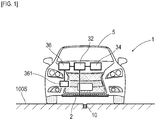
- Driving assist system 1 which is one example of the vehicle control system, is configured to include, as in FIG. 1 , measuring unit 2 which performs magnetic detection and so forth, tag reader 34 which obtains marker information regarding magnetic markers 10, control unit 32 which controls operation of the entire system, vehicle ECU 36, and so forth.
- Vehicle ECU 36 controls steering actuator 361 for steering the wheels to be steered based on a control signal inputted from control unit 32.
- Magnetic marker 10 to be laid in a road is generally described, and then details of measuring unit 2, tag reader 34, and control unit 32 are described.
- Magnetic marker 10 is, as in FIG. 1 to FIG. 3 , an example of a marker to be laid in road surface 100S of the road (one example of a traveling road) where vehicle 5 travels.
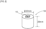
- This magnetic marker 10 forms a columnar shape having a diameter of 20 mm and a height of 28 mm.
- Magnetic marker 10 is laid, for example, in a state of being accommodated in a hole provided in road surface 100S ( FIG. 1 ).
- Magnetic marker 10 of the present embodiment are partially depicted in Table 1.
- Table 1 Magnet type Ferrite plastic magnet Diameter ⁇ 20mm Height 28mm Magnetic flux density Gs of the surface 4 5mT
- This magnetic marker 10 acts with magnetism of a magnetic flux density of 8 ⁇ T (microtesla) at an upper-limit height of 250 mm in a range from 100 mm to 250 mm assumed as an attachment height of measuring unit 2. Also, in this magnetic marker 10, a magnetic flux density Gs of the surface indicating a magnetic strength on the surface is 45 mT.
- Magnetic markers 10 are arranged, as in FIG. 3 , along the center of lane 100 sectioned by left and right lane marks at pitches of, for example, 2 meters (marker span M).
- a vehicle azimuth orientation of the vehicle in a longitudinal direction, azimuth
- a direction of a line segment connecting adjacent two magnetic markers 10 are along a lane direction.
- a designed laying position of each magnetic marker 10 is at the center of lane 100. Therefore, the direction of the line segment connecting adjacent two magnetic markers 10 is designed to match the lane direction (direction of the traveling road).
- an error in a laying position of magnetic marker 10 is inevitable.
- a direction of the actual line segment connecting adjacent two magnetic markers 10 has an azimuth error, and is deviated from the lane direction.
- azimuth dir the direction of the actual line segment connecting adjacent two magnetic markers 10 is referred to as azimuth dir(M).
- RFID (Radio Frequency IDentification) tag 15 is attached as a wireless tag which wirelessly outputs information (refer to FIG. 2 ).
- Marker information includes position data indicating the designed laying position of its corresponding magnetic marker 10, azimuth data (azimuth information, azimuth dir) indicating the lane direction, and so forth.
- azimuth dir indicating the lane direction can be found by calculation (target azimuth setting process, target azimuth setting part).
- the position data indicating the laying positions of adjacent two magnetic markers 10 may be included as azimuth information in the marker information.
- a laying position of immediately-previous magnetic marker 10 may be stored in advance on a vehicle 5 side and the laying position of immediately-previous magnetic marker 10 may be read when azimuth dir is calculated.
- the laying position of one magnetic marker 10 included in the marker information is one example of azimuth data (azimuth information).
- RFID tag 15 forming one example of the information providing part is an electronic component having IC chip 157 implemented on a surface of tag sheet 150 ( FIG. 4 ) cut out from, for example, a PET (PolyEthylene Terephthalate) film.
- IC chip 157 implemented on a surface of tag sheet 150 ( FIG. 4 ) cut out from, for example, a PET (PolyEthylene Terephthalate) film.
- a printed pattern of loop coil 151 and antenna 153 is provided on the surface of tag sheet 150.
- Loop coil 151 is a receiving coil where an exciting current is generated by external electromagnetic induction.
- Antenna 153 is a transmission antenna for wirelessly transmitting marker information.
- RFID tag 15 is arranged on an upward-oriented end face of magnetic marker 10.
- measuring unit 2 tag reader 34, and control unit 32 included in vehicle 5 are described.
- Measuring unit 2 is, as in FIG. 5 , a unit having sensor array 21 as a magnetic detecting part and IMU (Inertial Measurement Unit) 22 integrated together.
- Measuring unit 2 having a narrow rod shape is attached to, for example, the inside of front bumper or the like, in a state of facing road surface 100S (refer to FIG. 1 ).
- the attachment height of measuring unit 2 with reference to road surface 100S is 200 mm.
- Sensor array 21 of measuring unit 2 includes fifteen magnetic sensors Cn (n is an integer of 1 to 15) arrayed on one straight line and detection processing circuit 212 having a CPU and so forth not depicted incorporated therein.
- fifteen magnetic sensors Cn are equidistantly arranged with 10-centimeter pitches.
- Measuring unit 2 is attached to vehicle 5 so that an array direction of magnetic sensors Cn in sensor array 21 matches a vehicle-width direction.
- Magnetic sensors Cn are sensors which detect magnetism by using the known MI effect (Magneto Impedance Effect) in which impedance of a magneto-sensitive body such as an amorphous wire sensitively changes in response to an external magnetic field.
- MI effect Magnetic Impedance Effect
- magneto-sensitive bodies are arranged along two orthogonal axial directions, thereby allowing detection of magnetism acting on the two orthogonal axial directions.
- magnetic sensors Cn are incorporated in sensor array 21 so that magnetic components in a forwarding direction and magnetic components in the vehicle-width direction can be detected.
- Magnetic sensors Cn are highly-sensitive sensors having a measurement range of the magnetic flux density of ⁇ 0.6 mT and a magnetic flux resolution of 0.02 ⁇ T within the measurement range.
- a frequency of magnetic measurement by each magnetic sensor Cn of measuring unit 2 is set at 3 kHz so as to support high-speed traveling of vehicle 5.
- magnetic marker 10 can act with magnetism having the magnetic flux density equal to or larger than 8 ⁇ T in the range from 100 mm to 250 mm assumed as the attachment height of magnetic sensors Cn. Magnetic marker 10 acting with magnetism having the magnetic flux density equal to or larger than 8 ⁇ T can be detected with high reliability by using magnetic sensors Cn having the magnetic flux resolution of 0.02 ⁇ T.
- Detection processing circuit 212 ( FIG. 5 ) of sensor array 21 is an arithmetic circuit which performs marker detection process for detecting magnetic marker 10 and so forth.
- This detection processing circuit 212 is configured by using a CPU (Central Processing Unit) which performs various calculations, memory elements such as a ROM (Read Only Memory) and a RAM (Random Access Memory), and so forth.
- CPU Central Processing Unit
- memory elements such as a ROM (Read Only Memory) and a RAM (Random Access Memory), and so forth.
- Detection processing circuit 212 obtains a sensor signal outputted from each of magnetic sensors Cn at the frequency of 3 kHz to perform marker detection process. Detection processing circuit 212 inputs detection result of the marker detection process to control unit 32. Although details will be described further below, in this marker detection process, in addition to detection of magnetic marker 10, a lateral shift amount detection process is performed, in which a lateral shift amount of vehicle 5 with respect to detected magnetic marker 10 is measured.
- IMU 22 ( FIG. 5 ) incorporated in measuring unit 2 is an inertial navigation unit which estimates a relative position of vehicle 5 by inertial navigation.
- IMU 22 includes magnetic sensor 221 as an electronic compass which measures the azimuth, acceleration sensor 222 which measures acceleration, gyro sensor 223 which measures angular velocity, and so forth.
- Gyro sensor 223 measures angular velocity in a rotating direction about an axis in a vertical direction and outputs the angular velocity as a sensor output.
- IMU 22 calculates a displacement amount by double integration of the acceleration and integrates displacement amounts along the vehicle azimuth, thereby calculating a relative position with respect to a reference position. By using the relative position estimated by IMU 22, it is possible to estimate an own vehicle position also when vehicle 5 is positioned in an intermediate position between adjacent two magnetic markers 10.
- IMU 22 (one example of an azimuth measuring part and a generation processing part) temporarily integrates angular velocity (sensor output) measured by gyro sensor 223, thereby calculating measured azimuth Vs, which is a measured value of the vehicle azimuth (azimuth measuring process).
- Tag reader 34 is a communication unit which wirelessly communicates with RFID tag 15 arranged on a surface of magnetic marker 10.
- Tag reader 34 (one example of an information obtaining part) wirelessly transmits electric power required for operation of RFID tag 15, and receives marker information transmitted from RFID tag 15.
- marker information as described above, there are position data indicating the laying position (absolute position) of corresponding magnetic marker 10, azimuth dir which is azimuth data (azimuth information) indicating the lane direction, and so forth.
- Control unit 32 is a unit which controls measuring unit 2 and tag reader 34 and calculates a control value for lane keeping.
- the control value calculated by control unit 32 is inputted to vehicle ECU 36 which controls steering actuator 361.
- Control unit 32 includes an electronic substrate (omitted in the drawing) having implemented thereon a CPU which performs various computations, memory elements such as a ROM and a RAM, and so forth.
- the marker detection process is a process to be performed by sensor array 21 of measuring unit 2.
- Sensor array 21 performs marker detection process at the frequency of 3 kHz by using magnetic sensors Cn.
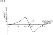
- magnetic sensor Cn is configured to measure magnetic components in the forwarding direction and magnetic components in the vehicle-width direction of vehicle 5. For example, when this magnetic sensor Cn moves in the forwarding direction to pass directly above magnetic marker 10, the magnetic measurement value in the forwarding direction has its sign reversed before and after passing magnetic marker 10 as in FIG. 6 and changes so as to cross zero at a position directly above magnetic marker 10. Therefore, during traveling of vehicle 5, when zero-cross Zc occurs in which the sign of the magnetic measurement value in the forwarding direction detected by any magnetic sensor Cn is reversed, it can be determined that measuring unit 2 is positioned directly above magnetic marker 10. Detection processing circuit 212 determines that magnetic marker 10 is detected when measuring unit 2 is positioned directly above magnetic marker 10 and zero-cross of the magnetic measurement value in the forwarding direction occurs as described above.
- the magnetic measurement value in the vehicle-width direction has its sign reversed on both sides across magnetic marker 10 and changes so as to cross zero at a position directly above magnetic marker 10.
- the sign of the magnetic measurement value in the vehicle-width direction to be detected by magnetic sensor Cn varies depending on which side the unit is present with respect to magnetic marker 10 ( FIG. 7 ).
- Detection processing circuit 212 measures a deviation of the position of magnetic marker 10 in the vehicle-width direction with respect to the center position (position of magnetic sensor C8) of measuring unit 2 as the lateral shift amount of vehicle 5 with respect to magnetic marker 10 (lateral shift amount detection process) .
- the position of zero-cross Zc is a position corresponding to C9.5 in the neighborhood of a midpoint between C9 and C10.
- the lateral shift amount of magnetic marker 10 is (9.5-8) ⁇ 10 cm with reference to C8 positioned at the center of measuring unit 2 in the vehicle-width direction. Then, the lateral shift amount, which is a deviation of vehicle 5 in the vehicle-width direction with reference to magnetic marker 10, can be calculated by reversing the sign of the above-described deviation (lateral shift amount detection process). Measuring unit 2 inputs, to control unit 32, the lateral shift amount with its sign reversed in accordance with to which side, left or right, vehicle 5 is shifted with respect to magnetic marker 10.
- control unit 32 controls the lane keeping function starting process by control unit 32 .
- control unit 32 While vehicle 5 is traveling, control unit 32 repeatedly performs marker detection process P1 (S101: NO). When magnetic marker 10 is detected (S101: YES), control unit 32 obtains the above-described lateral shift amount from measuring unit 2 (S102) . Control unit 32 handles the lateral shift amount obtained from measuring unit 2 as lateral shift amount OF of vehicle 5 with reference to magnetic marker 10.
- control unit 32 replaces data of lateral shift amounts OF1 and OF2 as occasion arises so that temporally-obsolete one is lateral shift amount OF1 and temporarily-new one is lateral shift amount OF2 (S103).
- control unit 32 calculates shift angle Ax of vehicle azimuth Vd with respect to direction dir(M) of the line segment connecting adjacent two magnetic markers 10 (S104, refer to FIG. 9 ).
- Control unit 32 calculates shift angle Ax by using lateral shift amounts OF1 and OF2 with respect to adjacent two magnetic markers 10.
- Lateral shift amounts OF1 and OF2 are defined so as to have a positive or a negative value by taking the center of vehicle 5 in the vehicle-width direction as a boundary.
- Shift angle Ax arcsin(OFd/M)
- Direction dir (M) of the actual line segment connecting adjacent two magnetic markers 10 is the absolute azimuth having an error in azimuth shift due to the error in the laying positions of magnetic markers 10. Since this azimuth shift error is indefinite, in the azimuth estimation process of the present embodiment, vehicle azimuth Vd with reference to the markers is estimated as follows, with reference to azimuth dir (marker information), which is a design value of the direction dir(M) of the line segment.
- control unit 32 After obtaining shift angle Ax in this manner, control unit 32 applies a threshold process to shift angle Ax (S105) .
- shift angle Ax is smaller than 5 degrees (S105: YES)
- control unit 32 determines that vehicle 5 is in a state of traveling along the lane, and sets a standby state of the lane keeping function (S106) .
- control unit 32 causes a display (omitted in the drawing) indicating that the lane keeping control can be started to be displayed on, for example, a screen of vehicle-onboard monitor 37 ( FIG. 5 , FIG. 10 ) where touch operation can be performed.
- setting screen 370 ( FIG. 10 ) for the lane keeping control.
- menu items 371 for setting a following distance, maximum speed, a traveling mode, whether to perform a lane change, and so forth
- start button 37S for starting the lane keeping control, and so forth.
- control unit 32 sets vehicle azimuth Vd with reference to the markers estimated as in FIG. 9 as an initial value of measured azimuth Vs measured by IMU 22 (S108), and then start the lane keeping control (S109).
- S108 start button 37S on setting screen 370
- S109 start the lane keeping control
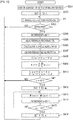
- control unit 32 During execution of the lane keeping control exemplarily depicted in FIG. 11 , control unit 32 repeatedly performs marker detection process P1.
- control unit 32 obtains lateral shift amount OF of vehicle 5 with respect to magnetic marker 10 from measuring unit 2, and obtains average lateral shift amount OFbar by a process of calculating an average value of lateral shift amounts OF for previous ten times (S202).
- this process of obtaining average lateral shift amount OFbar by averaging lateral shift amounts OF forms one example of a temporal filtering process of attenuating high-frequency components of change in the lateral shift amount.
- a filter process by a low-pass filter may be applied to attenuate high-frequency components.
- control unit 32 uses tag reader 34 to obtain marker information of RFID tag 15 attached to magnetic marker 10 (S203, information obtaining process). As described above, included in this marker information is azimuth dir, which is azimuth data indicating the lane direction. Control unit 32 (one example of a target azimuth setting part) sets azimuth dir, which is an absolute azimuth, as target azimuth Vo for the lane keeping control (S204, target azimuth setting process). On the other hand, when no magnetic marker 10 is detected (S201: NO), control unit 32 bypasses the processes from steps S202 to S204 described above. In this case, target azimuth Vo set at the immediately-previous magnetic marker detection is retained as being unchanged.
- control unit 32 After setting target azimuth Vo as described above, control unit 32 obtains measured azimuth Vs measured by IMU 22 (S205, azimuth measuring process).
- This measured azimuth Vs is an absolute azimuth calculated in the lane keeping function starting process exemplarily depicted in FIG. 8 .
- measured azimuth Vs is calculated by temporal integration of angular velocity, which is sensor output of gyro sensor 223.
- Control unit 32 multiplies azimuth deviation (Vo-Vs) (refer to FIG. 12 ) of measured azimuth Vs with reference to target azimuth Vo by coefficient "a", thereby calculating control value ⁇ S (S206). Furthermore, control unit 32 forming one example of a correcting part uses average lateral shift amount OFbar obtained at step S202 described above to perform correction of control value ⁇ S, which is an example of a degree of control (S207, correction process). Specifically, a correction amount obtained by multiplying average lateral shift amount OFbar, which is one example of a physical quantity based on lateral shift amounts OF, by correction coefficient "b" is added to control value ⁇ S to obtain new control value ⁇ S. This correction value acts so that lateral shift amount OF becomes closer to zero.
- Control unit 32 forming one example of a control part inputs this control value ⁇ S as the control signal to vehicle ECU 36 (S208, control process). Vehicle ECU 36 performs control on steering actuator 361 and so forth in accordance with inputted control value ⁇ S, thereby achieving automatic traveling of vehicle 5 by lane keeping.
- the traveling control method for vehicle 5 of the present embodiment is a traveling control method for achieving lane keeping by matching measured azimuth Vs regarding gyro sensor 223 with target azimuth Vo.
- This traveling control method has one of the technical features in that direct control by the lateral shift amount of vehicle 5 with respect to magnetic marker 10 is not performed. An advantageous effect obtained by this technical feature is described.
- the traveling control method of the present embodiment is based on control of bringing measured azimuth Vs measured by IMU 22 closer to target azimuth Vo based on azimuth dir indicating the lane direction.
- deviation (Vo-Vs) of measured azimuth Vs with respect to target azimuth Vo is a direct control target.
- degree of influence of the errors in the laying positions of magnetic markers 10 on the control is small.
- a temporal average process or the like is not applied to measured azimuth Vs, and thus a delay in control with respect to a change in target azimuth Vo is small and followability with respect to a change in curvature of the lane is not impaired.
- the traveling control method of the present embodiment in setting the initial value of measured azimuth Vs to be calculated by integration calculation by IMU 22 and correcting the degree of control, magnetic markers 10 are utilized.
- vehicle azimuth Vd with reference to the markers is set as the initial value of measured azimuth Vs measured by IMU 22.
- the control value is corrected by the lateral shift amount with respect to magnetic marker 10. If the control value (degree of control) for matching measured azimuth Vs with target azimuth Vo is corrected with the lateral shift amount, the deviation of vehicle 5 in the vehicle-width direction can be gradually eliminated.
- the control value is corrected by using average lateral shift amount OFbar, which is a temporal average value of lateral shift amount OF with respect to magnetic marker 10 for the previous ten times.
- average lateral shift amount OFbar is a physical quantity which has a reduced influence of the errors in the laying positions of magnetic markers 10 and reflects, with high accuracy, the deviation of vehicle 5 in the vehicle-width direction with reference to the designed laying line.
- control value may be corrected by, in place of average lateral shift amount OFbar, for example, a physical amount obtained by performing a filter process such as a high-cut filter or a low-pass filter which attenuates high-frequency components on temporal change in the lateral shift amount.
- the control value can also be corrected by the lateral shift amount itself measured in marker detection process P1.
- the correction coefficient is preferably set at a small value. With the correction coefficient having the small value, correction of the control value is moderate, meandering driving of the vehicle due to errors in the lateral shift amount can be suppressed before it happens.
- magnetic markers 10 magnetically detectable as markers are exemplarily described.
- passive-type markers may be adopted, such as, for example, embedded tiles or prints recognizable as images.
- Traveling control as an application target may be automatic traveling control by lane keeping, automatic traveling control for traveling along a specific road including lane changes, or almost-complete automatic traveling control including selection of a route to a destination. Even a route including lane changes, branching and merging, left and right turns at intersections, and so forth is one mode of the traveling road where markers are arrayed.
- vehicle 5 where sensor arrays 21 are arranged in the longitudinal direction of vehicle 5 with a pitch of 2 m ( FIG. 13 ) maybe adopted.
- front and rear sensor arrays 21 can simultaneously detect adjacent two magnetic markers 10.
- Shift angle Ax arcsin(OFd/M)
- azimuth dir indicating the lane direction may be obtained based on the laying positions (absolute positions) of adjacent two magnetic markers 10 and set as a target azimuth (target azimuth setting process).
- RFID tag 15 may be configured so as to output marker information including position information indicating the laying position of the magnetic marker. In this case, by the information obtaining process performed on a vehicle side, the marker information including the position information indicating the laying position of the magnetic marker can be read.
- IMU 22 is exemplarily described as an azimuth measuring part.
- the configuration for measuring the vehicle azimuth is not limited to IMU 22 of the present embodiment.
- the vehicle azimuth may be measured by an electronic compass using a geomagnetic sensor, a GPS compass using GPS (Global Positioning System), or the like.
- the target azimuth setting part of the present embodiment sets azimuth dir, which is azimuth data indicating the lane direction, as a target azimuth for the lane keeping control. That is, in a configuration of the present embodiment, azimuth dir itself, indicating the lane direction forming one example of the direction of the traveling road, is set as the target azimuth corresponding to the direction of the traveling road. In place of this, an azimuth identified based on azimuth dir indicating the lane direction may be taken as the target azimuth corresponding to the direction of the traveling road. For example, the target azimuth based on azimuth dir may be obtained by using an arithmetic equation with the degree of change in the direction of the traveling road as a variable.
- the traveling road with a large degree of change in the direction of the traveling road with a small radius of curvature such as a sharp curve or corner
- a vehicle with a large inner wheel difference such as a large truck or bus
- the direction of a path for traveling with a large turn may be set as the target azimuth corresponding to the direction of the traveling road.
- the large-turn path can be calculated with an arithmetic equation in which, for example, a vehicle's specification value such as a dimension of a wheel base is set as a variable.
- the present embodiment is an example based on the traveling control method of the first embodiment added with a process of correcting measured azimuth Vs measured by IMU 22. Details of this are described with reference to FIG. 14 and FIG. 15 .
- vehicle azimuth Vd with reference to the markers is estimated. Then, during execution of this traveling control, measured azimuth Vs is corrected by using vehicle azimuth Vd with reference to the markers .
- vehicle azimuth Vd with reference to the markers includes an error due to an error in a laying position of magnetic marker 10.
- the correction process of FIG. 14 is a process of correcting measured azimuth Vs by using vehicle azimuth Vd with reference to the markers including the error.
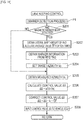
- control unit 32 controls IMU 22 so as to start integration calculation of output (angular velocity, sensor output) of gyro sensor 223 (S301).
- integration calculation of sensor output measured azimuth Vs is generated, which is a measured value of the vehicle azimuth.
- control unit 32 sets 0, which is an initial value, to variable n for use during the process (S302).
- Control unit 32 during execution of the lane keeping control controls sensor array 21 to repeatedly perform marker detection process P1 including the lateral shift amount detection process (S303: NO).
- control unit 32 first increments variable n by 1 (S304) .
- control unit 32 controls tag reader 34 to read the marker information from RFID tag 15 (S305, information obtaining process).
- azimuth data azimuth dir
- azimuth dir azimuth data in the lane direction corresponding to the direction of the designed line segment connecting two magnetic markers 10.
- control unit 32 estimates vehicle azimuth Vd by using the lateral shift amounts with respect to magnetic markers 10 (S306, azimuth estimation process). Details of this azimuth estimation process are similar to those of the process described in the first embodiment with reference to FIG. 9 . Also, control unit 32 obtains measured azimuth Vs measured by IMU 22 (S307).
- Control unit 32 causes a difference between measured azimuth Vs and vehicle azimuth Vd to be stored as error E(n) of measured azimuth Vs and causes a time (current time) at the time of measurement of measured azimuth Vs to be stored as t(n) (S308, generation process). In this manner, control unit 32 generates a data string formed of a combination of error E(n) and time t(n).
- E is an angular amount representing an error of measured azimuth Vs
- T is time.
- "b" is an intercept of the approximate straight line.
- control unit 32 calculates corrected measurement azimuth Vsm by subtracting error E (correction amount) from measured azimuth Vs (S310) .
- error E is (a ⁇ To+b).
- control unit 32 When variable n reaches 100 and a string of 100 pieces of data E(1) ... E(100) is formed (S311: YES), control unit 32 performs process for retaining the string of 100 pieces of data E(1) ... E(100) as the latest data. To perform this process, control unit 32 first sets 1 to variable m (S312). Then, control unit 32 rewrites m-th error E(m) as (m+1)-th error E(m+1) and rewrites m-th time t(m) as (m+1)-th time t(m+1) (S313).
- Control unit 32 increments variable m by 1 (S314) and repeats the rewrite process at step S313 until variable m reaches 100 (S315: NO).
- variable m reaches 100 (S315: YES)
- dataE(1) which is the most temporally-obsolete data of the original string of 100 pieces of data E(1) ... E(100)
- E(2) ... E(100) is sequentially brought down to form a string of 99 pieces of data E(1) ... E(99).
- control unit 32 sets 99 to variable n as preparation for the next process loop (S316), and then performs the next loop.
- control unit 32 sets new error data to E(100) to form a string of the latest 100 pieces of data E(1) ... E(100). Then, with the string of the latest data E(1) ... E(100), control unit 32 performs the process of linear approximation (S309), the process of correcting measured azimuth Vs (S310), and so forth.
- driving assist system 1 of the present embodiment performs correction of measured azimuth Vs by using vehicle azimuth Vd with reference to the markers.
- corrected measured azimuth Vsm With improved accuracy as a control target, it is possible to cause vehicle 5 to travel with high accuracy by traveling control such as lane keeping control.
- correction of subtracting offset "a” from the output (angular velocity) of the gyro sensor may be performed and then a measured azimuth may be obtained by time integration.
- the "b" portion of the correction amount of (a ⁇ To+b) to be subtracted from measured azimuth Vs is a portion corresponding to an initial value of the difference between measured azimuth Vs and vehicle azimuth Vd.
- measured azimuth Vs of gyro sensor 223 can be corrected by using magnetic markers 10. With an improvement in accuracy of the measured azimuth of gyro sensor 223, it is possible to improve accuracy in traveling control such as lane keeping control.
- azimuth data azimuth information
- azimuth dir indicating a designed direction of the line segment connecting adjacent two magnetic markers 10
- the azimuth information is not necessarily information of the azimuth itself.
- a combination of the laying positions (absolute positions) of adjacent two magnetic markers 10 or the like can be one example of azimuth information which can identify the azimuth. Note that other configurations and operations and effects are similar to those of the first embodiment.
- the present embodiment is an example in which, in the traveling control method of the second embodiment, details of the process of correcting measured azimuth Vs are changed. Details of this are described with reference to the flow diagram of FIG. 16 .
- the drawing is an alternative diagram of FIG. 14 , which is referred to in the second embodiment.
- processes until vehicle azimuth Vd with reference to the markers and measured azimuth Vs are obtained are similar to the processes from S301 to S307 in FIG. 14 of the second embodiment.
- control unit 32 After vehicle azimuth Vd with reference to the markers and measured azimuth Vs are obtained, the control unit (reference sign 32 in FIG. 5 ) of the present embodiment obtains the difference between measured azimuth Vs and vehicle azimuth Vd, and regards and stores this difference as error E(n) of measured azimuth Vs (S408) . Then, control unit 32 obtains average value AV (one example of correction information) of E(1) ... E(n) (S409, correction information generation process).
- AV one example of correction information
- Control unit 32 handles average value AV obtained at step S409 as a correction amount (correction information), and subtracts average value AV from measured azimuth Vs obtained at step S307 (shifts measured azimuth Vs by average value AV), thereby obtaining corrected measured azimuth Vsm (S410). Furthermore, control unit 32 recalculates error E(n) with corrected measured azimuth Vsm and causes the result to be stored (S410).
- the correction process of FIG. 16 is repeatedly performed, and E(n) is sequentially added until variable n reaches 10 (flow from S411: NO to S408) .
- S411: NO a period until variable n reaches 10 (S411: NO)
- calculation of average value AV at step S409 and calculation of a corrected value at step S410 are performed.
- control unit 32 When variable n reaches 10 and a string of 10 pieces of data E(1) ... E(10) is formed (S411: YES), control unit 32 performs process for retaining the string of 10 pieces of data E (1) ... E(10) as the latest data (series of processes from S411 to S416). These processes are almost similar to the processes from step S311 to S316 in FIG. 14 referred to in the second embodiment, except for a difference in number of pieces of data in the string between 10 and 100. After the number of pieces of data in the string reaches 10, with 10 pieces of E(n), calculation of average value AV at step S409 and calculation of the corrected value at step S410 are performed.
- measured azimuth Vs is corrected by using the average value of errors E(n) in measured azimuth Vs.
- vehicle azimuth Vd which is an azimuth serving as a reference, is estimated by using magnetic markers. As described in the second embodiment, there are errors in laying positions of the magnetic markers, and deviation from a designed laying line is inevitable. And, the errors in the laying positions of the magnetic markers directly lead to an error in vehicle azimuth Vd estimated on a vehicle side.
- a total sum of errors E(n) in measured azimuth Vs is calculated and is then divided by variable n indicating the number of pieces of data to obtain average value AV.
- n indicating the number of pieces of data
- the above-described error in vehicle azimuth Vd can be cancelled.
- measured azimuth Vs can be corrected with high accuracy while influence of the error in the laying positions of magnetic markers 10 is suppressed.
- the number of pieces of data is set to 10 as a population to calculate average value AV of errors E (n) when the process of correcting measured azimuth Vs is performed in the present embodiment, this number of pieces of data can be changed as appropriate. In place of 10, the number may be 20 or 30.
- the process of correcting measured azimuth Vs of the present embodiment and the process of correcting measured azimuth Vs of the second embodiment may be combined.
- the correction process of the present embodiment may be applied in a period with a small number of pieces of data immediately after the lane keeping control is started, and the correction process of the second embodiment may be applied in a period with 100 pieces of data or more.
Landscapes
- Engineering & Computer Science (AREA)
- Remote Sensing (AREA)
- Radar, Positioning & Navigation (AREA)
- Physics & Mathematics (AREA)
- General Physics & Mathematics (AREA)
- Automation & Control Theory (AREA)
- Aviation & Aerospace Engineering (AREA)
- Signal Processing (AREA)
- Chemical & Material Sciences (AREA)
- Electromagnetism (AREA)
- Mechanical Engineering (AREA)
- Transportation (AREA)
- Combustion & Propulsion (AREA)
- Analytical Chemistry (AREA)
- Multimedia (AREA)
- Manufacturing & Machinery (AREA)
- Navigation (AREA)
- Control Of Position, Course, Altitude, Or Attitude Of Moving Bodies (AREA)
- Traffic Control Systems (AREA)
- Control Of Driving Devices And Active Controlling Of Vehicle (AREA)
- Steering Control In Accordance With Driving Conditions (AREA)
Applications Claiming Priority (3)
| Application Number | Priority Date | Filing Date | Title |
|---|---|---|---|
| JP2018248445 | 2018-12-28 | ||
| JP2019037864 | 2019-03-01 | ||
| PCT/JP2019/051550 WO2020138471A1 (fr) | 2018-12-28 | 2019-12-27 | Procédé de commande de déplacement pour véhicule et système de commande de véhicule |
Publications (3)
| Publication Number | Publication Date |
|---|---|
| EP3904188A1 true EP3904188A1 (fr) | 2021-11-03 |
| EP3904188A4 EP3904188A4 (fr) | 2022-10-26 |
| EP3904188B1 EP3904188B1 (fr) | 2024-02-07 |
Family
ID=71127148
Family Applications (2)
| Application Number | Title | Priority Date | Filing Date |
|---|---|---|---|
| EP19906349.6A Active EP3904188B1 (fr) | 2018-12-28 | 2019-12-27 | Procédé de commande de déplacement pour véhicule et système de commande de véhicule |
| EP19903290.5A Active EP3904187B1 (fr) | 2018-12-28 | 2019-12-27 | Procédé de correction pour capteur gyroscopique |
Family Applications After (1)
| Application Number | Title | Priority Date | Filing Date |
|---|---|---|---|
| EP19903290.5A Active EP3904187B1 (fr) | 2018-12-28 | 2019-12-27 | Procédé de correction pour capteur gyroscopique |
Country Status (6)
| Country | Link |
|---|---|
| US (2) | US11808575B2 (fr) |
| EP (2) | EP3904188B1 (fr) |
| JP (2) | JP7421111B2 (fr) |
| CN (2) | CN113260544B (fr) |
| SG (2) | SG11202107068PA (fr) |
| WO (2) | WO2020138471A1 (fr) |
Families Citing this family (16)
| Publication number | Priority date | Publication date | Assignee | Title |
|---|---|---|---|---|
| JP6928307B2 (ja) * | 2017-03-28 | 2021-09-01 | 愛知製鋼株式会社 | マーカ検出システム及びマーカ検出方法 |
| JP6965815B2 (ja) * | 2018-04-12 | 2021-11-10 | 愛知製鋼株式会社 | マーカ検出システム、及びマーカ検出システムの運用方法 |
| US11604476B1 (en) * | 2018-10-05 | 2023-03-14 | Glydways Inc. | Road-based vehicle guidance system |
| JP7179644B2 (ja) * | 2019-02-25 | 2022-11-29 | 三菱重工エンジニアリング株式会社 | 制御装置、移動体および制御方法 |
| EP3954968A4 (fr) * | 2019-04-09 | 2023-05-03 | Pioneer Corporation | Dispositif d'estimation de position, dispositif d'estimation, procédé de commande, programme et support d'informations |
| EP3996991B1 (fr) * | 2019-07-11 | 2024-02-28 | BAE SYSTEMS plc | Initiateur et procédé |
| US11505900B2 (en) * | 2020-01-31 | 2022-11-22 | Rupert R. Thomas, Sr. | Elevated roadway quasi-equilibrium support system |
| CN113724133B (zh) * | 2021-08-06 | 2024-03-05 | 武汉极目智能技术有限公司 | 一种非刚体连接的拖挂车360°环视拼接方法 |
| JP2023050720A (ja) * | 2021-09-30 | 2023-04-11 | 愛知製鋼株式会社 | 制御方法及び制御システム |
| JP7682444B2 (ja) * | 2021-11-30 | 2025-05-26 | 村田機械株式会社 | 走行車システム、及びマーカのズレ量検出方法 |
| JP2024142581A (ja) * | 2023-03-30 | 2024-10-11 | 愛知製鋼株式会社 | 磁気マーカの検出方法、及び検出システム |
| CN116513175B (zh) * | 2023-07-03 | 2023-09-22 | 北京斯年智驾科技有限公司 | 一种自动驾驶中行驶偏差的校正方法、装置、设备及介质 |
| JP2025083722A (ja) * | 2023-11-21 | 2025-06-02 | 財団法人車輌研究測試中心 | 仮想軌道における車両の移動決定システム及びその方法 |
| US12479469B2 (en) * | 2023-11-22 | 2025-11-25 | Automotive Research & Testing Center | Deciding system for moving vehicle on virtual rail and method thereof |
| US20250321104A1 (en) * | 2024-04-11 | 2025-10-16 | The Research Foundation For The State University Of New York | Crowd-sourced road geometry estimation and applications thereof |
| JP2025166459A (ja) | 2024-04-24 | 2025-11-06 | 愛知製鋼株式会社 | 磁気マーカの施工方法および施工用の補助工具 |
Family Cites Families (39)
| Publication number | Priority date | Publication date | Assignee | Title |
|---|---|---|---|---|
| JP2665738B2 (ja) * | 1986-07-11 | 1997-10-22 | 株式会社小松製作所 | 地点追従方式による無人移動機械の誘導方法 |
| JP2572968B2 (ja) * | 1986-07-14 | 1997-01-16 | 株式会社椿本チエイン | 自律走行車の誘導方法 |
| JPS63241609A (ja) | 1987-03-30 | 1988-10-06 | Hitachi Ltd | 自走ロボツトの走行制御方法 |
| US5764014A (en) * | 1996-02-01 | 1998-06-09 | Mannesmann Dematic Rapistan Corp. | Automated guided vehicle having ground track sensor |
| JPH10105232A (ja) * | 1996-09-30 | 1998-04-24 | Mitsubishi Motors Corp | 自動運転道路システム用車線変更装置 |
| JP3743070B2 (ja) | 1996-09-30 | 2006-02-08 | 住友電気工業株式会社 | 車両の方位算出装置 |
| JP3328939B2 (ja) * | 1996-11-25 | 2002-09-30 | トヨタ自動車株式会社 | 車両用ナビゲーション装置及びこれに使用する道路形状データの作成 |
| JP3755217B2 (ja) * | 1996-11-29 | 2006-03-15 | 住友電気工業株式会社 | 車両の位置算出装置 |
| JP3780617B2 (ja) * | 1997-04-28 | 2006-05-31 | 日産自動車株式会社 | 車両の自動操舵装置 |
| JP3122761B2 (ja) * | 1998-07-31 | 2001-01-09 | 建設省土木研究所長 | 道路マーカ着磁装置 |
| JP2002023847A (ja) * | 2000-07-07 | 2002-01-25 | Nippon Sharyo Seizo Kaisha Ltd | 無人搬送車の誘導装置 |
| JP2002063682A (ja) * | 2000-08-21 | 2002-02-28 | Nec Corp | 走行位置検出装置 |
| JP2005170608A (ja) * | 2003-12-11 | 2005-06-30 | Mitsubishi Heavy Ind Ltd | クレーンの走行制御装置及びクレーンの走行制御システム並びに自走式門型クレーン |
| JP2005202478A (ja) | 2004-01-13 | 2005-07-28 | Denso Corp | 車両用自動走行システム |
| EP1924981B1 (fr) * | 2005-07-26 | 2012-09-12 | MacDonald Dettwiler & Associates Inc. | Systeme de gestion de traffic adapte a un environnement de type corridor |
| EP2306423B1 (fr) * | 2008-07-10 | 2013-04-10 | Mitsubishi Electric Corporation | Dispositif d'assistance au déplacement de convoi de véhicules |
| US8031086B2 (en) * | 2008-12-10 | 2011-10-04 | Deere & Company | Method and system for determining a position of a vehicle |
| JP5639874B2 (ja) * | 2010-12-24 | 2014-12-10 | 株式会社日立製作所 | 運転支援装置 |
| JP6005491B2 (ja) * | 2012-11-30 | 2016-10-12 | 株式会社小糸製作所 | 車両用灯具の制御装置及び車両用灯具システム |
| FR3012597B1 (fr) | 2013-10-24 | 2019-08-09 | Commissariat A L'energie Atomique Et Aux Energies Alternatives | Procede de localisation en interieur et exterieur et dispositif portatif mettant en œuvre un tel procede |
| US20150247719A1 (en) * | 2014-03-03 | 2015-09-03 | Tomorrow's Transportation Today | Position sensing system for intelligent vehicle guidance |
| JP6442993B2 (ja) | 2014-11-07 | 2018-12-26 | アイシン・エィ・ダブリュ株式会社 | 自動運転支援システム、自動運転支援方法及びコンピュータプログラム |
| JP6369399B2 (ja) * | 2015-06-26 | 2018-08-08 | 株式会社デンソー | センサ出力補正装置 |
| JP2017061281A (ja) * | 2015-09-25 | 2017-03-30 | 富士重工業株式会社 | 操舵支援制御装置 |
| EP3415691A4 (fr) * | 2016-02-10 | 2019-10-09 | Aichi Steel Corporation | Procédé d'installation de marqueur magnétique et système d'engin de chantier |
| US20190016339A1 (en) * | 2016-02-16 | 2019-01-17 | Honda Motor Co., Ltd. | Vehicle control device, vehicle control method, and vehicle control program |
| SG11201806864UA (en) * | 2016-02-16 | 2018-09-27 | Aichi Steel Corp | Work vehicle system and magnetic marker work method |
| US11921516B2 (en) * | 2016-04-28 | 2024-03-05 | Aichi Steel Corporation | Magnetic marker and driving assistance system |
| JP6947171B2 (ja) * | 2016-04-28 | 2021-10-13 | 愛知製鋼株式会社 | 運転支援システム |
| JP6916784B2 (ja) * | 2016-06-03 | 2021-08-11 | 愛知製鋼株式会社 | 位置捕捉方法及びシステム |
| JP6766527B2 (ja) | 2016-08-30 | 2020-10-14 | 愛知製鋼株式会社 | 車両用システム及び進路推定方法 |
| SE540698C2 (en) | 2017-02-07 | 2018-10-16 | Scania Cv Ab | Method and control unit for estimating bias of yaw rate sensor |
| US11119499B2 (en) * | 2017-03-28 | 2021-09-14 | Aichi Steel Corporation | Marker system |
| JP6928306B2 (ja) * | 2017-03-28 | 2021-09-01 | 愛知製鋼株式会社 | 磁気マーカの施工方法及び作業システム |
| JP7036114B2 (ja) * | 2017-06-14 | 2022-03-15 | 愛知製鋼株式会社 | マーカ検出方法及び車両用システム |
| JP6828643B2 (ja) * | 2017-09-12 | 2021-02-10 | 愛知製鋼株式会社 | 位置捕捉システム及び位置捕捉方法 |
| JP7020348B2 (ja) * | 2018-08-30 | 2022-02-16 | トヨタ自動車株式会社 | 自車位置推定装置 |
| US11669098B2 (en) * | 2019-02-07 | 2023-06-06 | GM Global Technology Operations LLC | Method and apparatus for longitudinal motion control of a vehicle |
| US10984260B2 (en) * | 2019-05-23 | 2021-04-20 | GM Global Technology Operations LLC | Method and apparatus for controlling a vehicle including an autonomous control system |
-
2019
- 2019-12-27 CN CN201980086141.0A patent/CN113260544B/zh active Active
- 2019-12-27 US US17/417,795 patent/US11808575B2/en active Active
- 2019-12-27 JP JP2020562531A patent/JP7421111B2/ja active Active
- 2019-12-27 WO PCT/JP2019/051550 patent/WO2020138471A1/fr not_active Ceased
- 2019-12-27 EP EP19906349.6A patent/EP3904188B1/fr active Active
- 2019-12-27 SG SG11202107068PA patent/SG11202107068PA/en unknown
- 2019-12-27 WO PCT/JP2019/051546 patent/WO2020138470A1/fr not_active Ceased
- 2019-12-27 SG SG11202107078SA patent/SG11202107078SA/en unknown
- 2019-12-27 EP EP19903290.5A patent/EP3904187B1/fr active Active
- 2019-12-27 US US17/417,408 patent/US11906307B2/en active Active
- 2019-12-27 CN CN201980086097.3A patent/CN113260543B/zh active Active
- 2019-12-27 JP JP2020562532A patent/JP7260856B2/ja active Active
Also Published As
| Publication number | Publication date |
|---|---|
| US20220075385A1 (en) | 2022-03-10 |
| US20220074745A1 (en) | 2022-03-10 |
| WO2020138471A1 (fr) | 2020-07-02 |
| CN113260544B (zh) | 2024-11-26 |
| SG11202107068PA (en) | 2021-07-29 |
| EP3904188B1 (fr) | 2024-02-07 |
| JPWO2020138470A1 (ja) | 2021-11-04 |
| US11808575B2 (en) | 2023-11-07 |
| JPWO2020138471A1 (fr) | 2020-07-02 |
| CN113260543A (zh) | 2021-08-13 |
| CN113260543B (zh) | 2024-11-12 |
| EP3904187A4 (fr) | 2022-09-28 |
| WO2020138470A1 (fr) | 2020-07-02 |
| CN113260544A (zh) | 2021-08-13 |
| SG11202107078SA (en) | 2021-07-29 |
| EP3904187A1 (fr) | 2021-11-03 |
| JP7421111B2 (ja) | 2024-01-24 |
| EP3904187B1 (fr) | 2024-12-25 |
| EP3904188A4 (fr) | 2022-10-26 |
| US11906307B2 (en) | 2024-02-20 |
| JP7260856B2 (ja) | 2023-04-19 |
Similar Documents
| Publication | Publication Date | Title |
|---|---|---|
| EP3904188B1 (fr) | Procédé de commande de déplacement pour véhicule et système de commande de véhicule | |
| CN110419067B (zh) | 标识器系统 | |
| EP3508822B1 (fr) | Système et procédé d'apprentissage pour véhicule | |
| CN112204352B (zh) | 陀螺仪传感器的校正方法 | |
| JP6946695B2 (ja) | マーカシステム | |
| EP3683547B1 (fr) | Système de capture de position et procédé de capture de position | |
| US11231721B2 (en) | Marker system and operation method | |
| CN113993762B (zh) | 车辆用的控制方法 | |
| EP3508811B1 (fr) | Système de détection d'orientation de véhicule | |
| US20240393801A1 (en) | Control method and control system |
Legal Events
| Date | Code | Title | Description |
|---|---|---|---|
| STAA | Information on the status of an ep patent application or granted ep patent |
Free format text: STATUS: THE INTERNATIONAL PUBLICATION HAS BEEN MADE |
|
| PUAI | Public reference made under article 153(3) epc to a published international application that has entered the european phase |
Free format text: ORIGINAL CODE: 0009012 |
|
| STAA | Information on the status of an ep patent application or granted ep patent |
Free format text: STATUS: REQUEST FOR EXAMINATION WAS MADE |
|
| 17P | Request for examination filed |
Effective date: 20210622 |
|
| AK | Designated contracting states |
Kind code of ref document: A1 Designated state(s): AL AT BE BG CH CY CZ DE DK EE ES FI FR GB GR HR HU IE IS IT LI LT LU LV MC MK MT NL NO PL PT RO RS SE SI SK SM TR |
|
| DAV | Request for validation of the european patent (deleted) | ||
| DAX | Request for extension of the european patent (deleted) | ||
| A4 | Supplementary search report drawn up and despatched |
Effective date: 20220926 |
|
| RIC1 | Information provided on ipc code assigned before grant |
Ipc: G08G 1/042 20060101ALI20220920BHEP Ipc: G08G 1/02 20060101ALI20220920BHEP Ipc: G01C 25/00 20060101ALI20220920BHEP Ipc: G01C 19/5776 20120101ALI20220920BHEP Ipc: G01C 21/16 20060101ALI20220920BHEP Ipc: G05D 1/02 20200101ALI20220920BHEP Ipc: G01C 21/28 20060101ALI20220920BHEP Ipc: B62D 6/00 20060101ALI20220920BHEP Ipc: B60W 30/12 20200101ALI20220920BHEP Ipc: G08G 1/00 20060101ALI20220920BHEP Ipc: B62D 137/00 20060101AFI20220920BHEP |
|
| GRAP | Despatch of communication of intention to grant a patent |
Free format text: ORIGINAL CODE: EPIDOSNIGR1 |
|
| STAA | Information on the status of an ep patent application or granted ep patent |
Free format text: STATUS: GRANT OF PATENT IS INTENDED |
|
| INTG | Intention to grant announced |
Effective date: 20230906 |
|
| P01 | Opt-out of the competence of the unified patent court (upc) registered |
Effective date: 20231110 |
|
| GRAS | Grant fee paid |
Free format text: ORIGINAL CODE: EPIDOSNIGR3 |
|
| GRAA | (expected) grant |
Free format text: ORIGINAL CODE: 0009210 |
|
| STAA | Information on the status of an ep patent application or granted ep patent |
Free format text: STATUS: THE PATENT HAS BEEN GRANTED |
|
| AK | Designated contracting states |
Kind code of ref document: B1 Designated state(s): AL AT BE BG CH CY CZ DE DK EE ES FI FR GB GR HR HU IE IS IT LI LT LU LV MC MK MT NL NO PL PT RO RS SE SI SK SM TR |
|
| REG | Reference to a national code |
Ref country code: GB Ref legal event code: FG4D |
|
| REG | Reference to a national code |
Ref country code: CH Ref legal event code: EP |
|
| REG | Reference to a national code |
Ref country code: NL Ref legal event code: FP Ref country code: IE Ref legal event code: FG4D |
|
| REG | Reference to a national code |
Ref country code: DE Ref legal event code: R096 Ref document number: 602019046340 Country of ref document: DE |
|
| REG | Reference to a national code |
Ref country code: SE Ref legal event code: TRGR |
|
| REG | Reference to a national code |
Ref country code: LT Ref legal event code: MG9D |
|
| PG25 | Lapsed in a contracting state [announced via postgrant information from national office to epo] |
Ref country code: IS Free format text: LAPSE BECAUSE OF FAILURE TO SUBMIT A TRANSLATION OF THE DESCRIPTION OR TO PAY THE FEE WITHIN THE PRESCRIBED TIME-LIMIT Effective date: 20240607 |
|
| PG25 | Lapsed in a contracting state [announced via postgrant information from national office to epo] |
Ref country code: LT Free format text: LAPSE BECAUSE OF FAILURE TO SUBMIT A TRANSLATION OF THE DESCRIPTION OR TO PAY THE FEE WITHIN THE PRESCRIBED TIME-LIMIT Effective date: 20240207 |
|
| PG25 | Lapsed in a contracting state [announced via postgrant information from national office to epo] |
Ref country code: GR Free format text: LAPSE BECAUSE OF FAILURE TO SUBMIT A TRANSLATION OF THE DESCRIPTION OR TO PAY THE FEE WITHIN THE PRESCRIBED TIME-LIMIT Effective date: 20240508 |
|
| REG | Reference to a national code |
Ref country code: AT Ref legal event code: MK05 Ref document number: 1655208 Country of ref document: AT Kind code of ref document: T Effective date: 20240207 |
|
| PG25 | Lapsed in a contracting state [announced via postgrant information from national office to epo] |
Ref country code: RS Free format text: LAPSE BECAUSE OF FAILURE TO SUBMIT A TRANSLATION OF THE DESCRIPTION OR TO PAY THE FEE WITHIN THE PRESCRIBED TIME-LIMIT Effective date: 20240507 Ref country code: HR Free format text: LAPSE BECAUSE OF FAILURE TO SUBMIT A TRANSLATION OF THE DESCRIPTION OR TO PAY THE FEE WITHIN THE PRESCRIBED TIME-LIMIT Effective date: 20240207 |
|
| PG25 | Lapsed in a contracting state [announced via postgrant information from national office to epo] |
Ref country code: ES Free format text: LAPSE BECAUSE OF FAILURE TO SUBMIT A TRANSLATION OF THE DESCRIPTION OR TO PAY THE FEE WITHIN THE PRESCRIBED TIME-LIMIT Effective date: 20240207 |
|
| PG25 | Lapsed in a contracting state [announced via postgrant information from national office to epo] |
Ref country code: AT Free format text: LAPSE BECAUSE OF FAILURE TO SUBMIT A TRANSLATION OF THE DESCRIPTION OR TO PAY THE FEE WITHIN THE PRESCRIBED TIME-LIMIT Effective date: 20240207 |
|
| PG25 | Lapsed in a contracting state [announced via postgrant information from national office to epo] |
Ref country code: RS Free format text: LAPSE BECAUSE OF FAILURE TO SUBMIT A TRANSLATION OF THE DESCRIPTION OR TO PAY THE FEE WITHIN THE PRESCRIBED TIME-LIMIT Effective date: 20240507 Ref country code: NO Free format text: LAPSE BECAUSE OF FAILURE TO SUBMIT A TRANSLATION OF THE DESCRIPTION OR TO PAY THE FEE WITHIN THE PRESCRIBED TIME-LIMIT Effective date: 20240507 Ref country code: LT Free format text: LAPSE BECAUSE OF FAILURE TO SUBMIT A TRANSLATION OF THE DESCRIPTION OR TO PAY THE FEE WITHIN THE PRESCRIBED TIME-LIMIT Effective date: 20240207 Ref country code: IS Free format text: LAPSE BECAUSE OF FAILURE TO SUBMIT A TRANSLATION OF THE DESCRIPTION OR TO PAY THE FEE WITHIN THE PRESCRIBED TIME-LIMIT Effective date: 20240607 Ref country code: HR Free format text: LAPSE BECAUSE OF FAILURE TO SUBMIT A TRANSLATION OF THE DESCRIPTION OR TO PAY THE FEE WITHIN THE PRESCRIBED TIME-LIMIT Effective date: 20240207 Ref country code: GR Free format text: LAPSE BECAUSE OF FAILURE TO SUBMIT A TRANSLATION OF THE DESCRIPTION OR TO PAY THE FEE WITHIN THE PRESCRIBED TIME-LIMIT Effective date: 20240508 Ref country code: FI Free format text: LAPSE BECAUSE OF FAILURE TO SUBMIT A TRANSLATION OF THE DESCRIPTION OR TO PAY THE FEE WITHIN THE PRESCRIBED TIME-LIMIT Effective date: 20240207 Ref country code: ES Free format text: LAPSE BECAUSE OF FAILURE TO SUBMIT A TRANSLATION OF THE DESCRIPTION OR TO PAY THE FEE WITHIN THE PRESCRIBED TIME-LIMIT Effective date: 20240207 Ref country code: BG Free format text: LAPSE BECAUSE OF FAILURE TO SUBMIT A TRANSLATION OF THE DESCRIPTION OR TO PAY THE FEE WITHIN THE PRESCRIBED TIME-LIMIT Effective date: 20240207 Ref country code: AT Free format text: LAPSE BECAUSE OF FAILURE TO SUBMIT A TRANSLATION OF THE DESCRIPTION OR TO PAY THE FEE WITHIN THE PRESCRIBED TIME-LIMIT Effective date: 20240207 |
|
| PG25 | Lapsed in a contracting state [announced via postgrant information from national office to epo] |
Ref country code: PT Free format text: LAPSE BECAUSE OF FAILURE TO SUBMIT A TRANSLATION OF THE DESCRIPTION OR TO PAY THE FEE WITHIN THE PRESCRIBED TIME-LIMIT Effective date: 20240607 Ref country code: PL Free format text: LAPSE BECAUSE OF FAILURE TO SUBMIT A TRANSLATION OF THE DESCRIPTION OR TO PAY THE FEE WITHIN THE PRESCRIBED TIME-LIMIT Effective date: 20240207 |
|
| PG25 | Lapsed in a contracting state [announced via postgrant information from national office to epo] |
Ref country code: PT Free format text: LAPSE BECAUSE OF FAILURE TO SUBMIT A TRANSLATION OF THE DESCRIPTION OR TO PAY THE FEE WITHIN THE PRESCRIBED TIME-LIMIT Effective date: 20240607 Ref country code: PL Free format text: LAPSE BECAUSE OF FAILURE TO SUBMIT A TRANSLATION OF THE DESCRIPTION OR TO PAY THE FEE WITHIN THE PRESCRIBED TIME-LIMIT Effective date: 20240207 Ref country code: LV Free format text: LAPSE BECAUSE OF FAILURE TO SUBMIT A TRANSLATION OF THE DESCRIPTION OR TO PAY THE FEE WITHIN THE PRESCRIBED TIME-LIMIT Effective date: 20240207 |
|
| PG25 | Lapsed in a contracting state [announced via postgrant information from national office to epo] |
Ref country code: DK Free format text: LAPSE BECAUSE OF FAILURE TO SUBMIT A TRANSLATION OF THE DESCRIPTION OR TO PAY THE FEE WITHIN THE PRESCRIBED TIME-LIMIT Effective date: 20240207 |
|
| PG25 | Lapsed in a contracting state [announced via postgrant information from national office to epo] |
Ref country code: SM Free format text: LAPSE BECAUSE OF FAILURE TO SUBMIT A TRANSLATION OF THE DESCRIPTION OR TO PAY THE FEE WITHIN THE PRESCRIBED TIME-LIMIT Effective date: 20240207 |
|
| PG25 | Lapsed in a contracting state [announced via postgrant information from national office to epo] |
Ref country code: CZ Free format text: LAPSE BECAUSE OF FAILURE TO SUBMIT A TRANSLATION OF THE DESCRIPTION OR TO PAY THE FEE WITHIN THE PRESCRIBED TIME-LIMIT Effective date: 20240207 Ref country code: EE Free format text: LAPSE BECAUSE OF FAILURE TO SUBMIT A TRANSLATION OF THE DESCRIPTION OR TO PAY THE FEE WITHIN THE PRESCRIBED TIME-LIMIT Effective date: 20240207 |
|
| PG25 | Lapsed in a contracting state [announced via postgrant information from national office to epo] |
Ref country code: SK Free format text: LAPSE BECAUSE OF FAILURE TO SUBMIT A TRANSLATION OF THE DESCRIPTION OR TO PAY THE FEE WITHIN THE PRESCRIBED TIME-LIMIT Effective date: 20240207 |
|
| PG25 | Lapsed in a contracting state [announced via postgrant information from national office to epo] |
Ref country code: SM Free format text: LAPSE BECAUSE OF FAILURE TO SUBMIT A TRANSLATION OF THE DESCRIPTION OR TO PAY THE FEE WITHIN THE PRESCRIBED TIME-LIMIT Effective date: 20240207 Ref country code: SK Free format text: LAPSE BECAUSE OF FAILURE TO SUBMIT A TRANSLATION OF THE DESCRIPTION OR TO PAY THE FEE WITHIN THE PRESCRIBED TIME-LIMIT Effective date: 20240207 Ref country code: RO Free format text: LAPSE BECAUSE OF FAILURE TO SUBMIT A TRANSLATION OF THE DESCRIPTION OR TO PAY THE FEE WITHIN THE PRESCRIBED TIME-LIMIT Effective date: 20240207 Ref country code: EE Free format text: LAPSE BECAUSE OF FAILURE TO SUBMIT A TRANSLATION OF THE DESCRIPTION OR TO PAY THE FEE WITHIN THE PRESCRIBED TIME-LIMIT Effective date: 20240207 Ref country code: DK Free format text: LAPSE BECAUSE OF FAILURE TO SUBMIT A TRANSLATION OF THE DESCRIPTION OR TO PAY THE FEE WITHIN THE PRESCRIBED TIME-LIMIT Effective date: 20240207 Ref country code: CZ Free format text: LAPSE BECAUSE OF FAILURE TO SUBMIT A TRANSLATION OF THE DESCRIPTION OR TO PAY THE FEE WITHIN THE PRESCRIBED TIME-LIMIT Effective date: 20240207 |
|
| REG | Reference to a national code |
Ref country code: DE Ref legal event code: R097 Ref document number: 602019046340 Country of ref document: DE |
|
| PLBE | No opposition filed within time limit |
Free format text: ORIGINAL CODE: 0009261 |
|
| STAA | Information on the status of an ep patent application or granted ep patent |
Free format text: STATUS: NO OPPOSITION FILED WITHIN TIME LIMIT |
|
| 26N | No opposition filed |
Effective date: 20241108 |
|
| PG25 | Lapsed in a contracting state [announced via postgrant information from national office to epo] |
Ref country code: SI Free format text: LAPSE BECAUSE OF FAILURE TO SUBMIT A TRANSLATION OF THE DESCRIPTION OR TO PAY THE FEE WITHIN THE PRESCRIBED TIME-LIMIT Effective date: 20240207 |
|
| PG25 | Lapsed in a contracting state [announced via postgrant information from national office to epo] |
Ref country code: MC Free format text: LAPSE BECAUSE OF FAILURE TO SUBMIT A TRANSLATION OF THE DESCRIPTION OR TO PAY THE FEE WITHIN THE PRESCRIBED TIME-LIMIT Effective date: 20240207 |
|
| REG | Reference to a national code |
Ref country code: CH Ref legal event code: PL |
|
| PG25 | Lapsed in a contracting state [announced via postgrant information from national office to epo] |
Ref country code: LU Free format text: LAPSE BECAUSE OF NON-PAYMENT OF DUE FEES Effective date: 20241227 |
|
| REG | Reference to a national code |
Ref country code: BE Ref legal event code: MM Effective date: 20241231 |
|
| PG25 | Lapsed in a contracting state [announced via postgrant information from national office to epo] |
Ref country code: BE Free format text: LAPSE BECAUSE OF NON-PAYMENT OF DUE FEES Effective date: 20241231 |
|
| PG25 | Lapsed in a contracting state [announced via postgrant information from national office to epo] |
Ref country code: CH Free format text: LAPSE BECAUSE OF NON-PAYMENT OF DUE FEES Effective date: 20241231 |
|
| PG25 | Lapsed in a contracting state [announced via postgrant information from national office to epo] |
Ref country code: IE Free format text: LAPSE BECAUSE OF NON-PAYMENT OF DUE FEES Effective date: 20241227 |
|
| PGFP | Annual fee paid to national office [announced via postgrant information from national office to epo] |
Ref country code: DE Payment date: 20251211 Year of fee payment: 7 |
|
| PGFP | Annual fee paid to national office [announced via postgrant information from national office to epo] |
Ref country code: GB Payment date: 20251219 Year of fee payment: 7 |
|
| PGFP | Annual fee paid to national office [announced via postgrant information from national office to epo] |
Ref country code: IT Payment date: 20251223 Year of fee payment: 7 |
|
| PGFP | Annual fee paid to national office [announced via postgrant information from national office to epo] |
Ref country code: FR Payment date: 20251229 Year of fee payment: 7 Ref country code: NL Payment date: 20251219 Year of fee payment: 7 |
|
| PGFP | Annual fee paid to national office [announced via postgrant information from national office to epo] |
Ref country code: SE Payment date: 20251219 Year of fee payment: 7 |