EP3904603B1 - Fraise pour parois moulées - Google Patents
Fraise pour parois moulées Download PDFInfo
- Publication number
- EP3904603B1 EP3904603B1 EP20172107.3A EP20172107A EP3904603B1 EP 3904603 B1 EP3904603 B1 EP 3904603B1 EP 20172107 A EP20172107 A EP 20172107A EP 3904603 B1 EP3904603 B1 EP 3904603B1
- Authority
- EP
- European Patent Office
- Prior art keywords
- oil
- heat exchanger
- cutter according
- bearing plate
- trench cutter
- Prior art date
- Legal status (The legal status is an assumption and is not a legal conclusion. Google has not performed a legal analysis and makes no representation as to the accuracy of the status listed.)
- Active
Links
Images

Classifications
-
- E—FIXED CONSTRUCTIONS
- E02—HYDRAULIC ENGINEERING; FOUNDATIONS; SOIL SHIFTING
- E02F—DREDGING; SOIL-SHIFTING
- E02F5/00—Dredgers or soil-shifting machines for special purposes
- E02F5/02—Dredgers or soil-shifting machines for special purposes for digging trenches or ditches
- E02F5/08—Dredgers or soil-shifting machines for special purposes for digging trenches or ditches with digging wheels turning round an axis
-
- E—FIXED CONSTRUCTIONS
- E02—HYDRAULIC ENGINEERING; FOUNDATIONS; SOIL SHIFTING
- E02D—FOUNDATIONS; EXCAVATIONS; EMBANKMENTS; UNDERGROUND OR UNDERWATER STRUCTURES
- E02D17/00—Excavations; Bordering of excavations; Making embankments
- E02D17/13—Foundation slots or slits; Implements for making these slots or slits
-
- E—FIXED CONSTRUCTIONS
- E02—HYDRAULIC ENGINEERING; FOUNDATIONS; SOIL SHIFTING
- E02F—DREDGING; SOIL-SHIFTING
- E02F3/00—Dredgers; Soil-shifting machines
- E02F3/04—Dredgers; Soil-shifting machines mechanically-driven
- E02F3/18—Dredgers; Soil-shifting machines mechanically-driven with digging wheels turning round an axis, e.g. bucket-type wheels
- E02F3/22—Component parts
- E02F3/24—Digging wheels; Digging elements of wheels; Drives for wheels
- E02F3/246—Digging wheels; Digging elements of wheels; Drives for wheels drives
-
- E—FIXED CONSTRUCTIONS
- E02—HYDRAULIC ENGINEERING; FOUNDATIONS; SOIL SHIFTING
- E02F—DREDGING; SOIL-SHIFTING
- E02F5/00—Dredgers or soil-shifting machines for special purposes
- E02F5/02—Dredgers or soil-shifting machines for special purposes for digging trenches or ditches
- E02F5/14—Component parts for trench excavators, e.g. indicating devices travelling gear chassis, supports, skids
-
- E—FIXED CONSTRUCTIONS
- E02—HYDRAULIC ENGINEERING; FOUNDATIONS; SOIL SHIFTING
- E02F—DREDGING; SOIL-SHIFTING
- E02F3/00—Dredgers; Soil-shifting machines
- E02F3/04—Dredgers; Soil-shifting machines mechanically-driven
- E02F3/18—Dredgers; Soil-shifting machines mechanically-driven with digging wheels turning round an axis, e.g. bucket-type wheels
- E02F3/20—Dredgers; Soil-shifting machines mechanically-driven with digging wheels turning round an axis, e.g. bucket-type wheels with tools that only loosen the material, i.e. mill-type wheels
- E02F3/205—Dredgers; Soil-shifting machines mechanically-driven with digging wheels turning round an axis, e.g. bucket-type wheels with tools that only loosen the material, i.e. mill-type wheels with a pair of digging wheels, e.g. slotting machines
Definitions
- the invention relates to a trench wall cutter with at least one pair of cutting wheels, at least one bearing plate on which the cutting wheels of a pair are rotatably arranged on both sides of the bearing plate, a base frame on the underside of which at least one bearing plate is attached, and a cutting wheel drive for driving the Milling wheels via a gear lubricated with gear oil in the end shield, according to the preamble of claim 1.
- a generic trench cutter is from EP 1 637 794 B1 known.
- an oil circuit is arranged between the cutting wheels, which are arranged at a lower end of the bearing plate, and a frame housing with the cutting wheel drive. Oil is conveyed from the auger wheels up through the auger blade to the auger wheel drive in the housing by the drive shaft. An oil return follows via a return line in the end shield. During operation, the end shield is covered on both sides by the milling wheels and the support suspension can hardly flow around it.
- Another generic trench cutter is from EP 1 580 327 B1 known.
- a drive torque from an individual drive motor is transmitted via a central drive shaft in a bearing plate to a sun wheel, from which the torque is distributed to the individual pairs of cutting wheels.
- EP 2 924 174 A1 , EP 3 467 209 A1 and JP-H07 138 979 A1 show well-known trench cutters with their mechanical design of the cutter wheel gears. In some cases, the hydraulic connection of the various components is also shown.
- the invention is based on the object of specifying a trench wall cutter in which a particularly high cutting capacity is ensured with reliable lubrication of a gear arrangement for driving the cutting wheels.
- the trench cutter according to the invention is characterized in that at least one heat exchanger is arranged above the bearing plate and that an oil circuit is designed to cool the transmission oil, to which at least one heat exchanger is connected above the bearing plate.
- a basic idea of the invention is based on the knowledge that the gear arrangement in a trench wall cutter is exposed to considerable forces, particularly when cutting through harder soil or rock layers, which can result in the gear oil being heated to a great extent. Excessive heating of the gear oil can cause a lubricating film to break off on contacting gears and lead to increased wear on the gears and bearings. This can limit the milling performance and shorten the service life of the gearbox.
- an oil circuit with at least one heat exchanger through which the transmission oil is conducted.
- the heat exchanger is located away from the milling point and the end shield with the gear, namely above the end shield.
- the oil circuit can be formed by means of oil lines.
- targeted cooling takes place at an exposed area in the fluid-filled milling slot of the housing above the milling wheels and above the end shield.
- This area on or even above the base frame offers the possibility of a very large wall construction of a preferably plate-shaped heat exchanger.
- Several heat exchangers can also be arranged. In this way, even if the transmission oil in the oil circuit heats up considerably, it can be cooled down to a desired operating temperature, so that the oil has a desired viscosity for forming a stable lubricating film during operation. In this way, particularly high milling performance can be achieved.
- a preferred embodiment of the invention is that the heat exchanger is designed as a plate which is detachably attached to the base frame or to a holding device above the base frame.
- the heat exchanger can therefore be attached to struts of the base frame or to the holding device on which the base frame is suspended.
- the holding device can be a guide rod, a holding cable and/or feed lines.
- the milling drive is arranged in a housing and that the heat exchanger is formed in or on an outer wall of the housing.
- the base frame is essentially formed by the housing of the milling wheel drive.
- the heat exchanger can be designed in a compact manner on the housing.
- the outer wall of the housing is designed as a cooling wall, with at least one groove being introduced on an inside of the cooling wall to form an oil duct, in which a hose-shaped or tubular line is arranged.
- the at least one outer wall of the housing can be designed as a cooling wall in which at least one oil duct is arranged, oil for cooling being able to be conducted through the at least one oil duct in the outer wall of the housing.
- a preferred embodiment of the invention consists, in particular, in that the oil duct is designed in the shape of a loop, preferably in a meandering shape, in the outer wall of the housing.
- the oil in the cooling wall can be cooled particularly strongly and quickly.
- the heat exchanger is designed in particular as a separate plate which is detachably fastened. This means that existing trench cutters can also be retrofitted or converted.
- the plate can be in two parts, with a cover plate covering an oil duct in a base plate.
- the cooling plate can also be applied, in particular screwed, to a smooth-surfaced housing wall.
- a particularly expedient embodiment is achieved according to a further development of the invention in that at least one groove is introduced to form the oil duct on an inside of the cooling wall, in which a hose or tubular line is arranged.
- the groove can accordingly run in a loop or meander shape.
- the plate-shaped heat exchanger comprises a metal with high thermal conductivity, in particular aluminum or an aluminum alloy.
- a metal is provided which has a higher thermal conductivity than steel.
- a particularly strong cooling effect can be achieved in this way. In a test, a cooling capacity of approx. 3.2 kW was achieved when using a steel plate, while a cooling capacity of approx. 11.2 kW was achieved when using an aluminum plate.
- a further preferred embodiment of the invention consists in that at least one pumping device is provided, through which the oil in the oil circuit can be pumped.
- the pump device can be an electrically or hydraulically driven pump, preferably with a variable delivery volume.
- the pump device can be driven by a control device, which changes the delivery flow through the oil duct depending on the current oil temperature, which can be detected, for example, by a temperature sensor. Heat can be dissipated as required in this way.
- a particularly simple configuration of a trench wall cutter according to the invention is achieved in that the pump device comprises a shaft driven by the cutter drive, which shaft is provided on its outside with at least one conveying helix to form a worm pump.
- the shaft of the pumping device can be driven in rotation by the cutting wheel drive via a separate drive train.
- the shaft is the drive shaft, which extends from the cutting wheel drive through the bearing plate to the cutting wheels.
- the drive shaft runs essentially vertically and is provided on its outside with a conveyor helix, in particular grooves, through which oil in the shaft channel is conveyed upwards along the shaft by the cutting wheels.
- the cutting wheel drive preferably includes one or more hydraulic motors.
- a control valve which blocks an oil line channel of the oil circuit at a first low temperature and releases the oil line channel at a second, higher temperature.
- the control valve can be actuated depending on the oil temperature by the control already mentioned above. In particular when starting the cutting wheel drive with a low temperature of the gear oil, the oil duct will be blocked so that the gear oil is heated to the operating temperature as quickly as possible. When a second, higher temperature is exceeded, the control valve can then open and release the oil line channel. Thus, oil can flow through the oil duct into the heat exchanger, so that a corresponding cooling can be achieved.
- the at least one cooling wall can be arranged at any point on the outside of the housing or the milling frame. According to one embodiment of the invention, it is particularly advantageous that at least two cooling walls are provided, which are arranged on the longitudinal sides of the housing. As a result, sufficient cooling can also take place in the event of particularly strong heating.
- the housing can be designed as a lattice frame, on or in which one or more cooling plates are arranged.
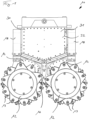
- a trench wall cutter 10 according to the invention 1 has a base frame 30 with a housing 31 on the underside of which two plate-shaped end shields 14 are attached.
- a cutting wheel 12 with a multiplicity of cutting teeth 13 for cutting off soil material are rotatably mounted on both sides of the bearing plates 14 .
- a wedge-shaped suspension feed 16 can be arranged between the two pairs of cutting wheels 12 on the underside of the base frame 30 .
- a support and milling suspension can be introduced into the milling slot formed via the suspension feed 16 .
- the supplied suspension can be provided with a binder, so-called soil cement can be formed by mixing it with the milled off soil fragments, which can harden in the milled trench to form a trench wall segment.
- Plate-shaped adjusting and guiding elements 18 are provided along the narrow sides of the base frame 30 . These can lie against the wall of the cut trench during cutting, with the trench wall cutter 10 being able to be guided and adjusted in the cut cut by a corresponding adjustment of the adjusting elements 18 .
- a cable suspension or a guide rod for holding and vertically adjusting the trench wall cutter 10 in the cut trench is provided in a known manner.
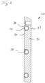
- a plate-shaped outer wall 32 is provided to form a heat exchanger 60, which as a in the figures 2 and 3 cooling wall 34 shown in detail is formed.
- the cooling wall 34 can form a wall of the housing 31 .
- the heat exchanger 60 with the cooling wall 34 is according to 3 designed as a flat plate, preferably made of stainless steel.
- the cooling wall 34 has an inner side 35 directed towards the housing 31 and an opposite outer side 37 which forms an outside of the housing 31 in the assembled state.
- a groove 38 is milled along the inside 35 of the cooling wall 34, which according to the representation of FIG 2 is designed meandering.
- a line 40 made of a metal tube, such as copper, is inserted.
- the line 40 thus forms the oil line channel 36 in the cooling wall 34.
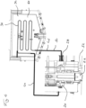
- the line 40 has connections 42 at its ends, with which the heat exchanger 60 can be connected to an oil circuit 50, which is partially shown schematically in FIG 4 is shown.
- a partially indicated cutting wheel drive 20 is shown with numerous bearings. From the cutting wheel drive 20, a drive shaft 22 (only partially shown) for each bearing plate 14 extends downwards to the cutting wheels 12 lying below.
- the drive shaft 22 is provided on its outside with conveying grooves, not shown, which can convey gear oil from the area of the cutting wheels 12 upwards in the direction of the cutting wheel drive 20 .
- the oil flows through the bearings and gear wheel arrangement of the only schematically indicated cutting wheel drive 20.
- the cutting wheel drive 20 can preferably include at least one hydraulic motor and an output and distribution gear.
- At least part of the transmission oil is conducted via a pump device (not shown) via a feed 44 of an oil circuit 50 to an upper connection of the heat exchanger 60 with a meandering oil duct 36 in the cooling wall 34 .
- the heated oil can flow through the meandering oil duct 36 in the cooling wall 34 from top to bottom and in the process emit heat to the cooling wall 34 with its free outer side facing the suspension-filled slot.
- the oil duct 36 can be formed in the cooling wall 34 with a slight gradient of, for example, approximately 15°, so that an oil flow can be set without a great deal of pressure being applied.
- the cooled transmission oil is routed back to the cutting wheel drive 20 via a return line 46 of the oil circuit 50 .
- the transmission oil can be routed downwards from the cutting wheel drive 20 to the cutting wheels with the distribution gear.
- the oil which has been heated up again in particular in the area of the distribution gear, can then be pumped upwards again via the conveying effect of the drive shaft 22 to the cutting wheel drive 20 and the heat exchanger 60 above the end shield 14 .
- a control valve 28 is provided on the supply line 44 or, as shown, on the return line 46 in order to control the flow of oil through the oil line channel 36 . At the intended temperatures, this can control the oil flow through the oil duct 36 and block or open it altogether. The control takes place depending on temperature sensors, not shown, which measure a temperature of the transmission oil at one or more points in the oil circuit 50 .
- the cooling circuit can also have a branch for pressure equalization of the transmission arrangement.
Landscapes
- Engineering & Computer Science (AREA)
- Mining & Mineral Resources (AREA)
- Mechanical Engineering (AREA)
- Civil Engineering (AREA)
- General Engineering & Computer Science (AREA)
- Structural Engineering (AREA)
- Life Sciences & Earth Sciences (AREA)
- General Life Sciences & Earth Sciences (AREA)
- Paleontology (AREA)
- General Details Of Gearings (AREA)
- Drilling And Boring (AREA)
Claims (10)
- Fraise pour parois moulées avec- au moins une paire de roues de fraisage (12),- au moins une flasque (14), au niveau de laquelle les roues de fraisage (12) d'une paire sont agencées de manière rotative, des deux côtés de la flasque (14),- un cadre de base (30), au niveau du côté inférieur duquel l'au moins une flasque (14) est montée, et- un entraînement de roue de fraisage (20) pour l'entraînement des roues de fraisage (12) par le biais d'un engrenage graissé avec de l'huile d'engrenage dans la flasque (14),caractérisée en ce que- au moins un échangeur de chaleur (60) est agencé au-dessus de la flasque (14) et- un circuit d'huile (50) est réalisé pour le refroidissement de l'huile d'engrenage, auquel l'au moins un échangeur de chaleur (60) est raccordé au-dessus de la flasque (14).
- Fraise pour parois moulées selon la revendication 1,
caractérisée en ce que
l'échangeur de chaleur (60) est réalisé comme une plaque qui est fixée de manière amovible au cadre de base (30) ou à un dispositif de retenue au-dessus du cadre de base (30). - Fraise pour parois moulées selon la revendication 1 ou 2,
caractérisée en ce quel'entraînement de fraisage (20) est agencé dans un boîtier (31) etl'échangeur de chaleur (60) est réalisé dans ou au niveau d'une paroi extérieure (32) du boîtier (30). - Fraise pour parois moulées selon la revendication 3,
caractérisée en ce que
la paroi extérieure (32) du boîtier (31) est réalisée comme une paroi de refroidissement (34), au moins une rainure (38) étant introduite pour la formation d'un canal de conduite d'huile (36), au niveau d'un côté intérieur de la paroi de refroidissement (34), dans laquelle une conduite (40) en forme de tuyau ou de tube est agencée. - Fraise pour parois moulées selon l'une quelconque des revendications 1 à 4,
caractérisée en ce que
l'échangeur de chaleur (60) en forme de plaque comporte un métal avec une conductivité thermique élevée, en particulier de l'aluminium ou un alliage d'aluminium. - Fraise pour parois moulées selon l'une quelconque des revendications 1 à 5,
caractérisée en ce que
au moins un dispositif de pompage est prévu, par lequel l'huile peut être refoulée dans le circuit d'huile (50). - Fraise pour parois moulées selon la revendication 6,
caractérisée en ce que
le dispositif de pompage comporte un arbre entraîné par l'entraînement de roue de fraisage (20) qui est pourvu au niveau de son côté extérieur d'au moins une hélice de refoulement. - Fraise pour parois moulées selon la revendication 7,
caractérisée en ce que
l'arbre est l'arbre d'entraînement (22) qui s'étend depuis l'entraînement de roue de fraisage (20) à travers la flasque (14) jusqu'aux roues de fraisage (12). - Fraise pour parois moulées selon l'une quelconque des revendications 1 à 8,
caractérisée en ce que
une soupape de commande (28) est prévue, laquelle bloque, à une première température faible, un canal de conduite d'huile (36) du circuit d'huile (50) à l'échangeur de chaleur (60) et libère, à une seconde température plus élevée, le canal de conduite d'huile (36). - Fraise pour parois moulées selon l'une quelconque des revendications 1 à 9,
caractérisée en ce que
au moins deux parois de refroidissement (34) sont prévues, lesquelles sont agencées au niveau des côtés longitudinaux du boîtier (30).
Priority Applications (4)
| Application Number | Priority Date | Filing Date | Title |
|---|---|---|---|
| EP20172107.3A EP3904603B1 (fr) | 2020-04-29 | 2020-04-29 | Fraise pour parois moulées |
| US17/997,475 US20230175230A1 (en) | 2020-04-29 | 2021-03-04 | Trench cutter |
| CN202180031702.4A CN115485436A (zh) | 2020-04-29 | 2021-03-04 | 槽壁铣削机 |
| PCT/EP2021/055501 WO2021219279A1 (fr) | 2020-04-29 | 2021-03-04 | Fraise pour parois moulées |
Applications Claiming Priority (1)
| Application Number | Priority Date | Filing Date | Title |
|---|---|---|---|
| EP20172107.3A EP3904603B1 (fr) | 2020-04-29 | 2020-04-29 | Fraise pour parois moulées |
Publications (3)
| Publication Number | Publication Date |
|---|---|
| EP3904603A1 EP3904603A1 (fr) | 2021-11-03 |
| EP3904603C0 EP3904603C0 (fr) | 2023-08-23 |
| EP3904603B1 true EP3904603B1 (fr) | 2023-08-23 |
Family
ID=70480123
Family Applications (1)
| Application Number | Title | Priority Date | Filing Date |
|---|---|---|---|
| EP20172107.3A Active EP3904603B1 (fr) | 2020-04-29 | 2020-04-29 | Fraise pour parois moulées |
Country Status (4)
| Country | Link |
|---|---|
| US (1) | US20230175230A1 (fr) |
| EP (1) | EP3904603B1 (fr) |
| CN (1) | CN115485436A (fr) |
| WO (1) | WO2021219279A1 (fr) |
Families Citing this family (1)
| Publication number | Priority date | Publication date | Assignee | Title |
|---|---|---|---|---|
| EP4455407A1 (fr) * | 2023-04-26 | 2024-10-30 | BAUER Maschinen GmbH | Dispositif d'excavation pour la construction de diaphragmes et procédé de réalisation d'une fouille de fondation |
Family Cites Families (11)
| Publication number | Priority date | Publication date | Assignee | Title |
|---|---|---|---|---|
| US4271879A (en) * | 1979-02-21 | 1981-06-09 | Deborah Shivers | Hydraulic stump cutting and digging apparatus |
| JP2921368B2 (ja) * | 1993-11-15 | 1999-07-19 | 株式会社大林組 | 掘削機 |
| EP1580327B1 (fr) | 2004-03-26 | 2008-05-21 | BAUER Maschinen GmbH | Appareil pour creuser des tranchées dans le sol |
| EP1637794B1 (fr) | 2004-09-16 | 2015-11-11 | BAUER Maschinen GmbH | Fraise pour parois moulées |
| FR2899608B1 (fr) * | 2006-04-06 | 2010-04-16 | Cie Du Sol | Outillage de forage |
| CN101285310B (zh) * | 2008-06-05 | 2010-08-18 | 谢沃林 | 一种双轮铣槽机 |
| CN103363273A (zh) * | 2012-04-08 | 2013-10-23 | 宁波市镇海捷登应用技术研究所 | 一种轴承及该轴承的润滑装置 |
| US20150041414A1 (en) * | 2013-08-09 | 2015-02-12 | Ledwell & Son Enterprises, Inc. | Hydraulic fluid cooler and filter |
| EP2924174B1 (fr) * | 2014-03-24 | 2018-12-26 | Soilmec S.p.A. | Équipement d'excavation à système hydraulique amélioré relatif |
| IT201700112156A1 (it) * | 2017-10-06 | 2019-04-06 | Soilmec Spa | Utensile di scavo per la realizzazione di diaframmi e relativa attrezzatura di scavo |
| DE102018131226A1 (de) * | 2018-12-06 | 2020-06-10 | Liebherr-Werk Nenzing Gmbh | Spezialtiefbaumaschine, insbesondere Schlitzwandfräse |
-
2020
- 2020-04-29 EP EP20172107.3A patent/EP3904603B1/fr active Active
-
2021
- 2021-03-04 WO PCT/EP2021/055501 patent/WO2021219279A1/fr not_active Ceased
- 2021-03-04 CN CN202180031702.4A patent/CN115485436A/zh active Pending
- 2021-03-04 US US17/997,475 patent/US20230175230A1/en active Pending
Also Published As
| Publication number | Publication date |
|---|---|
| US20230175230A1 (en) | 2023-06-08 |
| EP3904603C0 (fr) | 2023-08-23 |
| EP3904603A1 (fr) | 2021-11-03 |
| CN115485436A (zh) | 2022-12-16 |
| WO2021219279A1 (fr) | 2021-11-04 |
Similar Documents
| Publication | Publication Date | Title |
|---|---|---|
| EP3906369B1 (fr) | Dispositif de contrôle de la température pour les unités d'entraînement et/ou de transmission telles que les tunneliers | |
| WO1990011907A1 (fr) | Essieu moteur | |
| DE19912328A1 (de) | Vorrichtung zur Ölführung in einem Getriebe eines Kraftfahrzeuges | |
| DE1575972B2 (de) | Fluessigkeitsreibungskupplung | |
| EP3904603B1 (fr) | Fraise pour parois moulées | |
| DE102011108016A1 (de) | Selbstfahrender Oberflächenfräser | |
| DE112012004609B4 (de) | Schneckengetriebe | |
| EP2193907B1 (fr) | Machine à vis avec compensation axiale de la expansion thermique | |
| DE3409738C2 (fr) | ||
| EP2842716B1 (fr) | Machine à vis sans fin et procédé de préparation de matières plastiques en fusion | |
| DE19952166B4 (de) | Schweißgerät für thermoplastische Kunststoffe | |
| EP0401323B1 (fr) | Palier-guide pour l'enveloppe d'un cylindre de pression | |
| DE3045192A1 (de) | Zahnradpumpe | |
| DE102008052654A1 (de) | Vorrichtung, umfassend ein ein drehendes Teil umgebendes Gehäuse | |
| DE2347862C3 (de) | Kühleinrichtung für Gewinnungsmaschinen des Untertagebergbaus | |
| EP4455514B1 (fr) | Groupe motopropulseur | |
| AT413203B (de) | Anordnung von zwei oder mehreren eigenständigen getriebeeinheiten | |
| DE2123481C3 (de) | Am drehenden Kupplungsgehäuse einer hydrodynamischen Kupplung befestigter Zahnradring für den Antrieb eines Zahnradgetriebes | |
| EP3838074B1 (fr) | Appareil de cuisson, notamment appareil de cuisson sous pression | |
| DE102009024724A1 (de) | Getriebe für einen Kernumfassungsschrauben-Manipulator | |
| DE69717542T2 (de) | Antriebssystem für die Steuerachse eines mechanischen Kraftfahrzeuggetriebes | |
| DE19827598C1 (de) | Antriebswelle für einen Kettenförderer eines Zuckerrohrdiffuseurs | |
| DE3045324C2 (de) | Elektromechanischer Antrieb für ein kettengetriebenes Strebbetriebsmittel | |
| DE1817680B2 (de) | Gußwalzenanordnung zur Herstellung von-Walzglas | |
| DE2015112C2 (de) | Einrichtung zum stufenlosen Verstellen von Lauf- oder Leitradschaufeln oder beides gemeinsam von Kreiselmaschinen, wie Kreiselpumpen, Axialturbinen, Schiff sptopellern o. dgl |
Legal Events
| Date | Code | Title | Description |
|---|---|---|---|
| PUAI | Public reference made under article 153(3) epc to a published international application that has entered the european phase |
Free format text: ORIGINAL CODE: 0009012 |
|
| STAA | Information on the status of an ep patent application or granted ep patent |
Free format text: STATUS: THE APPLICATION HAS BEEN PUBLISHED |
|
| AK | Designated contracting states |
Kind code of ref document: A1 Designated state(s): AL AT BE BG CH CY CZ DE DK EE ES FI FR GB GR HR HU IE IS IT LI LT LU LV MC MK MT NL NO PL PT RO RS SE SI SK SM TR |
|
| B565 | Issuance of search results under rule 164(2) epc |
Effective date: 20200929 |
|
| STAA | Information on the status of an ep patent application or granted ep patent |
Free format text: STATUS: REQUEST FOR EXAMINATION WAS MADE |
|
| 17P | Request for examination filed |
Effective date: 20220216 |
|
| RBV | Designated contracting states (corrected) |
Designated state(s): AL AT BE BG CH CY CZ DE DK EE ES FI FR GB GR HR HU IE IS IT LI LT LU LV MC MK MT NL NO PL PT RO RS SE SI SK SM TR |
|
| GRAP | Despatch of communication of intention to grant a patent |
Free format text: ORIGINAL CODE: EPIDOSNIGR1 |
|
| STAA | Information on the status of an ep patent application or granted ep patent |
Free format text: STATUS: GRANT OF PATENT IS INTENDED |
|
| INTG | Intention to grant announced |
Effective date: 20230426 |
|
| GRAS | Grant fee paid |
Free format text: ORIGINAL CODE: EPIDOSNIGR3 |
|
| GRAA | (expected) grant |
Free format text: ORIGINAL CODE: 0009210 |
|
| STAA | Information on the status of an ep patent application or granted ep patent |
Free format text: STATUS: THE PATENT HAS BEEN GRANTED |
|
| AK | Designated contracting states |
Kind code of ref document: B1 Designated state(s): AL AT BE BG CH CY CZ DE DK EE ES FI FR GB GR HR HU IE IS IT LI LT LU LV MC MK MT NL NO PL PT RO RS SE SI SK SM TR |
|
| REG | Reference to a national code |
Ref country code: GB Ref legal event code: FG4D Free format text: NOT ENGLISH |
|
| REG | Reference to a national code |
Ref country code: CH Ref legal event code: EP |
|
| REG | Reference to a national code |
Ref country code: DE Ref legal event code: R096 Ref document number: 502020004808 Country of ref document: DE |
|
| REG | Reference to a national code |
Ref country code: IE Ref legal event code: FG4D Free format text: LANGUAGE OF EP DOCUMENT: GERMAN |
|
| U01 | Request for unitary effect filed |
Effective date: 20230823 |
|
| U07 | Unitary effect registered |
Designated state(s): AT BE BG DE DK EE FI FR IT LT LU LV MT NL PT SE SI Effective date: 20230828 |
|
| PG25 | Lapsed in a contracting state [announced via postgrant information from national office to epo] |
Ref country code: GR Free format text: LAPSE BECAUSE OF FAILURE TO SUBMIT A TRANSLATION OF THE DESCRIPTION OR TO PAY THE FEE WITHIN THE PRESCRIBED TIME-LIMIT Effective date: 20231124 |
|
| PG25 | Lapsed in a contracting state [announced via postgrant information from national office to epo] |
Ref country code: IS Free format text: LAPSE BECAUSE OF FAILURE TO SUBMIT A TRANSLATION OF THE DESCRIPTION OR TO PAY THE FEE WITHIN THE PRESCRIBED TIME-LIMIT Effective date: 20231223 |
|
| PG25 | Lapsed in a contracting state [announced via postgrant information from national office to epo] |
Ref country code: RS Free format text: LAPSE BECAUSE OF FAILURE TO SUBMIT A TRANSLATION OF THE DESCRIPTION OR TO PAY THE FEE WITHIN THE PRESCRIBED TIME-LIMIT Effective date: 20230823 Ref country code: NO Free format text: LAPSE BECAUSE OF FAILURE TO SUBMIT A TRANSLATION OF THE DESCRIPTION OR TO PAY THE FEE WITHIN THE PRESCRIBED TIME-LIMIT Effective date: 20231123 Ref country code: IS Free format text: LAPSE BECAUSE OF FAILURE TO SUBMIT A TRANSLATION OF THE DESCRIPTION OR TO PAY THE FEE WITHIN THE PRESCRIBED TIME-LIMIT Effective date: 20231223 Ref country code: HR Free format text: LAPSE BECAUSE OF FAILURE TO SUBMIT A TRANSLATION OF THE DESCRIPTION OR TO PAY THE FEE WITHIN THE PRESCRIBED TIME-LIMIT Effective date: 20230823 Ref country code: GR Free format text: LAPSE BECAUSE OF FAILURE TO SUBMIT A TRANSLATION OF THE DESCRIPTION OR TO PAY THE FEE WITHIN THE PRESCRIBED TIME-LIMIT Effective date: 20231124 |
|
| PG25 | Lapsed in a contracting state [announced via postgrant information from national office to epo] |
Ref country code: PL Free format text: LAPSE BECAUSE OF FAILURE TO SUBMIT A TRANSLATION OF THE DESCRIPTION OR TO PAY THE FEE WITHIN THE PRESCRIBED TIME-LIMIT Effective date: 20230823 |
|
| PG25 | Lapsed in a contracting state [announced via postgrant information from national office to epo] |
Ref country code: ES Free format text: LAPSE BECAUSE OF FAILURE TO SUBMIT A TRANSLATION OF THE DESCRIPTION OR TO PAY THE FEE WITHIN THE PRESCRIBED TIME-LIMIT Effective date: 20230823 |
|
| PG25 | Lapsed in a contracting state [announced via postgrant information from national office to epo] |
Ref country code: SM Free format text: LAPSE BECAUSE OF FAILURE TO SUBMIT A TRANSLATION OF THE DESCRIPTION OR TO PAY THE FEE WITHIN THE PRESCRIBED TIME-LIMIT Effective date: 20230823 Ref country code: RO Free format text: LAPSE BECAUSE OF FAILURE TO SUBMIT A TRANSLATION OF THE DESCRIPTION OR TO PAY THE FEE WITHIN THE PRESCRIBED TIME-LIMIT Effective date: 20230823 Ref country code: ES Free format text: LAPSE BECAUSE OF FAILURE TO SUBMIT A TRANSLATION OF THE DESCRIPTION OR TO PAY THE FEE WITHIN THE PRESCRIBED TIME-LIMIT Effective date: 20230823 Ref country code: CZ Free format text: LAPSE BECAUSE OF FAILURE TO SUBMIT A TRANSLATION OF THE DESCRIPTION OR TO PAY THE FEE WITHIN THE PRESCRIBED TIME-LIMIT Effective date: 20230823 Ref country code: SK Free format text: LAPSE BECAUSE OF FAILURE TO SUBMIT A TRANSLATION OF THE DESCRIPTION OR TO PAY THE FEE WITHIN THE PRESCRIBED TIME-LIMIT Effective date: 20230823 |
|
| REG | Reference to a national code |
Ref country code: DE Ref legal event code: R097 Ref document number: 502020004808 Country of ref document: DE |
|
| U20 | Renewal fee for the european patent with unitary effect paid |
Year of fee payment: 5 Effective date: 20240430 |
|
| PLBE | No opposition filed within time limit |
Free format text: ORIGINAL CODE: 0009261 |
|
| STAA | Information on the status of an ep patent application or granted ep patent |
Free format text: STATUS: NO OPPOSITION FILED WITHIN TIME LIMIT |
|
| 26N | No opposition filed |
Effective date: 20240524 |
|
| PG25 | Lapsed in a contracting state [announced via postgrant information from national office to epo] |
Ref country code: MC Free format text: LAPSE BECAUSE OF FAILURE TO SUBMIT A TRANSLATION OF THE DESCRIPTION OR TO PAY THE FEE WITHIN THE PRESCRIBED TIME-LIMIT Effective date: 20230823 |
|
| PG25 | Lapsed in a contracting state [announced via postgrant information from national office to epo] |
Ref country code: MC Free format text: LAPSE BECAUSE OF FAILURE TO SUBMIT A TRANSLATION OF THE DESCRIPTION OR TO PAY THE FEE WITHIN THE PRESCRIBED TIME-LIMIT Effective date: 20230823 |
|
| PG25 | Lapsed in a contracting state [announced via postgrant information from national office to epo] |
Ref country code: IE Free format text: LAPSE BECAUSE OF NON-PAYMENT OF DUE FEES Effective date: 20240429 |
|
| U20 | Renewal fee for the european patent with unitary effect paid |
Year of fee payment: 6 Effective date: 20250429 |
|
| PGFP | Annual fee paid to national office [announced via postgrant information from national office to epo] |
Ref country code: CH Payment date: 20250501 Year of fee payment: 6 |
|
| PG25 | Lapsed in a contracting state [announced via postgrant information from national office to epo] |
Ref country code: CY Free format text: LAPSE BECAUSE OF FAILURE TO SUBMIT A TRANSLATION OF THE DESCRIPTION OR TO PAY THE FEE WITHIN THE PRESCRIBED TIME-LIMIT; INVALID AB INITIO Effective date: 20200429 |
|
| PG25 | Lapsed in a contracting state [announced via postgrant information from national office to epo] |
Ref country code: HU Free format text: LAPSE BECAUSE OF FAILURE TO SUBMIT A TRANSLATION OF THE DESCRIPTION OR TO PAY THE FEE WITHIN THE PRESCRIBED TIME-LIMIT; INVALID AB INITIO Effective date: 20200429 |
|
| PGFP | Annual fee paid to national office [announced via postgrant information from national office to epo] |
Ref country code: GB Payment date: 20260330 Year of fee payment: 7 |