EP4455407A1 - Dispositif d'excavation pour la construction de diaphragmes et procédé de réalisation d'une fouille de fondation - Google Patents
Dispositif d'excavation pour la construction de diaphragmes et procédé de réalisation d'une fouille de fondation Download PDFInfo
- Publication number
- EP4455407A1 EP4455407A1 EP23170046.9A EP23170046A EP4455407A1 EP 4455407 A1 EP4455407 A1 EP 4455407A1 EP 23170046 A EP23170046 A EP 23170046A EP 4455407 A1 EP4455407 A1 EP 4455407A1
- Authority
- EP
- European Patent Office
- Prior art keywords
- electric motor
- cooling
- cooling medium
- diaphragm wall
- milling device
- Prior art date
- Legal status (The legal status is an assumption and is not a legal conclusion. Google has not performed a legal analysis and makes no representation as to the accuracy of the status listed.)
- Pending
Links
Images


Classifications
-
- E—FIXED CONSTRUCTIONS
- E02—HYDRAULIC ENGINEERING; FOUNDATIONS; SOIL SHIFTING
- E02D—FOUNDATIONS; EXCAVATIONS; EMBANKMENTS; UNDERGROUND OR UNDERWATER STRUCTURES
- E02D17/00—Excavations; Bordering of excavations; Making embankments
- E02D17/13—Foundation slots or slits; Implements for making these slots or slits
-
- E—FIXED CONSTRUCTIONS
- E02—HYDRAULIC ENGINEERING; FOUNDATIONS; SOIL SHIFTING
- E02F—DREDGING; SOIL-SHIFTING
- E02F3/00—Dredgers; Soil-shifting machines
- E02F3/04—Dredgers; Soil-shifting machines mechanically-driven
- E02F3/18—Dredgers; Soil-shifting machines mechanically-driven with digging wheels turning round an axis, e.g. bucket-type wheels
- E02F3/20—Dredgers; Soil-shifting machines mechanically-driven with digging wheels turning round an axis, e.g. bucket-type wheels with tools that only loosen the material, i.e. mill-type wheels
- E02F3/205—Dredgers; Soil-shifting machines mechanically-driven with digging wheels turning round an axis, e.g. bucket-type wheels with tools that only loosen the material, i.e. mill-type wheels with a pair of digging wheels, e.g. slotting machines
-
- H—ELECTRICITY
- H02—GENERATION; CONVERSION OR DISTRIBUTION OF ELECTRIC POWER
- H02K—DYNAMO-ELECTRIC MACHINES
- H02K5/00—Casings; Enclosures; Supports
- H02K5/04—Casings or enclosures characterised by the shape, form or construction thereof
- H02K5/20—Casings or enclosures characterised by the shape, form or construction thereof with channels or ducts for flow of cooling medium
- H02K5/203—Casings or enclosures characterised by the shape, form or construction thereof with channels or ducts for flow of cooling medium specially adapted for liquids, e.g. cooling jackets
-
- H—ELECTRICITY
- H02—GENERATION; CONVERSION OR DISTRIBUTION OF ELECTRIC POWER
- H02K—DYNAMO-ELECTRIC MACHINES
- H02K9/00—Arrangements for cooling or ventilating
- H02K9/19—Arrangements for cooling or ventilating for machines with closed casing and closed-circuit cooling using a liquid cooling medium, e.g. oil
Definitions
- the invention relates to a trench wall milling device with a trench wall milling machine with a frame, two pairs of milling wheels which are rotatably mounted on a lower region of the frame, at least one milling wheel drive by which the milling wheels can be driven in rotation, wherein the milling wheel drive has an electric motor for generating the rotational movement, and a cooling circuit for cooling the at least one electric motor with a cooling medium guided in the cooling circuit, according to the preamble of claim 1.
- the invention further relates to a method for creating a milling slot in the ground with a diaphragm wall milling device according to the preamble of claim 13.
- a trench wall milling device with a trench wall milling machine is known in which the milling wheels can be driven by an electric motor, which is arranged as a so-called attachment motor above the milling wheels.
- the torque can be transmitted to the milling wheels via a gear box, which are rotatably mounted on a bearing plate on the underside of a frame.
- a generic diaphragm wall milling device is in the EP 3 467 209 A1 described.
- the cutting wheels are driven by so-called hub motors, which are arranged in a hub area of the drum-shaped cutting wheels.
- hub motors When using electric motors, especially in a hub area of the cutting wheels, these must be actively cooled.
- a cooling circuit is described for cooling, in which a cooling device is mounted on a carrier device outside of the milling slot.
- a cooling medium is fed from the cooling device via pipes not only to the electric hub motors, but also to the electric drive of a suction pump. The cooling circuit allows heat to be released from the electric motors via the cooling device to the environment outside the milling slot.
- Diaphragm wall cutters are typically used and operated with a relatively narrow speed range of around 50 to 60 revolutions per minute with relatively small speed deviations up and down.
- a cooling system for a diaphragm wall cutter can therefore be designed relatively easily to meet an expected, largely constant cooling requirement.
- the invention is based on the object of specifying a diaphragm wall milling device and a method with which a diaphragm wall milling device can be used particularly efficiently and flexibly.
- the trench wall milling device is characterized in that a control unit is arranged for controlling the cooling circuit, that an operating state of the at least one electric motor can be detected by the control unit and that the control unit is designed to variably control a volume flow of cooling medium to the at least one electric motor depending on the detected operating state.
- a basic idea of the invention is to design a trench wall cutter of a trench wall cutter device to be compact on the one hand and particularly flexible on the other. This is achieved by providing at least one electric motor to drive the cutter wheels to generate the rotary movement of the cutter wheels, with variable cooling being provided depending on the operating state of the electric motor.
- the trench wall cutter can not only be used for normal milling operations with a limited range of speeds and torques, but also for mixing suspension with milling cuttings in the milling slot with significantly higher speeds and other torques.
- this is achieved primarily by arranging a control unit for variably controlling the cooling circuit of the at least one electric motor. The control unit detects an operating state of the electric motor.
- the operating state can preferably include the temperature of the electric motor, which can be detected directly on the motor or indirectly via the cooling medium emerging from the electric motor.
- a volume flow of cooling medium to the at least one electric motor can be variably controlled and adjusted. This enables efficient operation of the electric motor(s) over a wide load range, thus enabling a wide range of possible uses for the trench wall cutter.
- individual cooling of each individual electric motor can be provided.
- the term frame of the trench wall cutter is to be understood broadly and does not refer only to a scaffold-like frame construction, as is used in trench wall cutters in relatively large guide frames with guide plates. Rather, the term frame also includes compact housing-like basic components or frames of a trench wall cutter, on which the cutting wheels and drive units as well as any suction or feed device are arranged.
- the frame of a trench wall cutter can preferably be provided for guiding the trench wall cutter with guide elements relative to the surrounding trench wall.
- the frame can also have smaller cross-sectional dimensions than the milling cross-section, whereby the trench wall cutter is operated without the guide function of the frame.
- a particularly preferred embodiment of the invention is that the control unit controls a cooling medium pump which conveys a cooling medium to and/or from the at least one electric motor.
- the cooling medium pump can be driven by a motor, in particular by an electric motor.
- the motor of the cooling medium pump is controlled by the control unit according to a program specification and the detected operating state of the electric motor to be cooled. If there is a high cooling requirement, a correspondingly large volume flow of cooling medium can be supplied or discharged, while in the case of a The volume flow is reduced accordingly due to the reduced cooling requirement. In this way, the electric motor for rotating the cutting wheels can be kept and used at an efficient and largely constant operating temperature.
- the cooling medium can basically be a gas and preferably a liquid. In a simple case, water can be used as the cooling medium, although special cooling liquids can preferably be used.
- an alternative or additional possibility for variably setting the volume flow is that the control unit controls at least one control valve, by means of which a circulating flow of the cooling medium is variably divided into a first partial flow and at least one second partial flow, the first partial flow being formed to the at least one electric motor.
- the control valve can be controlled electromagnetically, for example, so that the control unit can direct a defined first partial flow of cooling medium from a circulating flow to the at least one electric motor.
- Additional control valves can also branch off additional partial flows, for example from a main circuit line, so that when several electric motors are provided, individual cooling of each individual electric motor can be achieved.
- the remaining at least one second partial flow can, in a simple case, be returned to an output cooling device as a return flow.
- the at least one second partial flow can also be used for further cooling purposes of other components. Branched partial flows can be returned again to form the circuit.
- At least a second partial flow of cooling medium is directed to a gearbox of the cutting wheel drive in order to cool a gearbox oil in the gearbox.
- a corresponding gearbox which comprises gear wheels in a gearbox housing filled with gearbox oil, can be arranged for torque transmission and torque conversion in both an attachment motor and a hub motor.
- a further advantageous embodiment of the invention is that the cutting wheel drive has a gearbox with a gearbox housing in which at least one heat exchanger, in particular for a second partial flow from the cooling circuit, is arranged for cooling the gearbox oil. This enables particularly efficient cooling of the gearbox oil.
- the heat exchanger within the gear housing it is particularly expedient for the heat exchanger within the gear housing to have heat exchange fins.
- An independent heat exchanger is thus provided within the cutting wheel gear, which can directly cool the gear oil within the gear housing using a cooling medium that is also used to cool the electric motor.
- a particularly efficient control is achieved in that at least one temperature sensor is provided, which is arranged in the area of the at least one electric motor for detecting the temperature of the electric motor and/or on the cooling circuit for detecting the temperature of the cooling medium, in particular after it exits the electric motor, and in that the at least one temperature sensor is connected to the control unit.
- the at least one temperature sensor is connected to the control unit.
- several temperature sensors are arranged, which can be positioned both on the electric motor and on the cooling circuit.
- the temperature of the stator, the rotor or another suitable component of the electric motor can be directly detected via a temperature sensor on the electric motor.
- the at least one temperature sensor can be arranged on the corresponding component.
- a temperature sensor on the cooling circuit can be used to detect a temperature of the cooling medium, preferably at the outlet from the electric motor, whereby the temperature of the cooling medium can be indirectly used to determine the temperature of the electric motor.
- the detected temperature value can be sent to the control unit in order to supply a larger volume flow of cooling medium to the electric motor, for example in the event of an excessively high temperature.
- the temperature of each electric motor can be recorded directly and/or indirectly and sent to the control unit. This enables Individual setting of the temperature for each electric motor. This allows particularly efficient and long-lasting operation of the electric motors.
- control unit can detect a speed and/or a torque for rotating the cutting wheels in order to control the cooling circuit. Based on the values recorded for the speed and/or torque for rotating the cutting wheels, the control unit can determine at an early stage whether increased heat development is occurring in the at least one electric motor. If the speed and torque increase, greater heat development is to be expected in the electric motor. The control unit can therefore adjust the volume flow of cooling medium to the at least one electric motor early and as required, i.e. increase or decrease it, before an actual temperature increase, thereby counteracting a temperature increase.
- the at least one coolant pump can be arranged at any location on the trench wall milling device.
- the coolant pump is arranged on a frame of the trench wall milling machine.
- the coolant pump can thus be positioned spatially close to the at least one electric motor for driving the milling wheels.
- a suction device for sucking up the removed soil material also known as milling cuttings
- the milling cuttings are thus removed from the soil to the surface and can be disposed of or returned to the cutter slot after processing.
- a further advantageous embodiment of a trench wall cutter according to the invention consists in that a feed opening for feeding a suspension is arranged on the frame in the area of the cutting wheels and that the trench wall cutter is designed to mix milled soil with fed suspension in order to form a soil mortar in the milled slot.
- the cutter can thus not only be used to remove soil material and to create the slot, but also to mix the milled cuttings with the soil that is fed through the feed opening.
- supplied suspension to form a soil mortar.
- the suspension can be a hardening suspension, such as a cement suspension.
- the soil mortar formed can remain in the milling slot after the diaphragm wall cutter is pulled out of the slot and harden to form a diaphragm wall segment.
- particularly efficient cooling can be achieved by providing a carrier device on which the trench wall cutter is held, and by arranging a cooling device for cooling the cooling medium on the carrier device.
- the heat absorbed by the cooling medium can be released to the environment via the cooling device by means of a heat exchanger, so that the cooling medium can be returned to the trench wall cutter in the circuit for further cooling of the electric motors.
- the cooling device can also be arranged on the frame of the trench wall cutter itself, whereby the heat can then be released directly into a suspension in the milling slot.
- each cutting wheel is assigned an electric motor, which is designed as a hub motor.
- An output shaft of the hub motor can drive the respectively assigned cutting wheel directly or with the interposition of a transmission, which is in particular a gear transmission, in particular a reduction gear.
- the trench wall cutter can basically be held vertically adjustable by means of a holding cable on a carrier device.
- Guidance can be provided by means of the frame, which is designed with guide plates for contacting and guiding along the walls of the milled slot.
- the trench wall cutter is held on a tubular guide rod, within which at least one line runs to form the cooling circuit. In this way, in certain cases undesirable heat transfer of the heat of the cooling medium into the suspension of the milled slot during the return line to the cooling device can be largely avoided.
- the guide rod can contribute to or provide guidance for the trench wall cutter, but does not have to do so in every case.
- the invention further relates to a method for creating a milling slot in the ground with a diaphragm wall milling device, wherein a diaphragm wall milling device according to the invention is used, as described above and/or specified in the claims.
- the method according to the invention can be used to achieve the previously described advantages when operating a diaphragm wall milling device or when creating a milling slot.
- the previously described diaphragm wall milling device according to the invention is also preferably designed to carry out the method according to the invention.
- a particularly preferred variant of the method according to the invention consists in that a volume flow of cooling medium to the electric motor is controlled and adjusted depending on a temperature of the electric motor and/or a temperature of the cooling medium and/or a speed and/or a torque for rotating the cutting wheels. This enables efficient operation of the at least one electric motor in a suitable operating temperature range. This reduces maintenance effort and increases the service life of the electric motor.
- the method can be used in a variety of ways.
- a diaphragm wall is formed in the milled slot created.
- the diaphragm wall can be formed by a soil mortar which is formed in the milled slot in situ by the milling wheels by mixing hardenable suspension. After the diaphragm wall cutter is withdrawn from the milled slot with the soil mortar thus formed, this can harden to form a diaphragm wall segment.
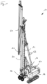
- a trench wall milling device 10 according to the invention with a carrier device 12 is shown in Figure 1
- the carrier device 12 can have a crawler chassis and a superstructure rotatably mounted thereon with an operating station.
- a control unit can be arranged on the operating station, which can be designed in particular to control the cooling of a trench wall cutter 30 during operation.
- a guide rod 22 can be held and mounted so that it can be moved vertically along the mast 14 to form a holding device 20.
- the trench wall cutter 30 can be attached to the guide rod 22 at the lower end of the holding device 20.
- a generally known cooling device 61 with a heat exchanger and at least one coolant pump can be arranged on the carrier device 12, in particular on the upper carriage of the carrier device 12.
- Cooling line hoses 62 can be led from the cooling device 61 to the mast 14 to an upper end of the holding device 20, in particular the guide rod 22, in order to form a cooling circuit 60 between the trench wall cutter 30 and the cooling device 61.
- Corresponding lines can extend within the tubular guide rod 22 to the trench wall cutter 30, which is described in more detail below.
- the basic structure of a trench cutter 30 is described in connection with the Figures 2 to 5
- the trench wall cutter 30 has a frame 32, which in the illustrated embodiment is compact and designed like a housing.
- the frame 32 shown has a cross-section which is smaller than the cross-section of the milling slot produced.
- the frame 32 can also be designed like a scaffold with guide plates which can be placed on the walls of the milling slot over a large area for guidance.
- Two plate-shaped bearing plates 34 can be arranged on an underside of the frame 32, on each of which a pair of milling wheels 40 are rotatably mounted. On each side of a bearing plate 34, a milling wheel 40 can be rotatably mounted coaxially to the opposite milling wheel 40 on the other side of the bearing plate 34.
- Each milling wheel 40 has a drum-shaped milling wheel hub 42, on the outside of which radially projecting plate-shaped tooth holders 44 each with at least one milling tooth 45 can be attached.
- at least one basically known folding tooth 46 can be arranged on each milling wheel 40. The folding tooth 46 can be moved between a retracted position and a Figure 4 shown unfolded position, in which it is shown in the illustration of Figure 4 soil material below the bearing plate 34 can be removed.
- a feed device 37 with at least one feed opening 38 for feeding a milling suspension can be arranged on the underside of the frame 32.
- plate-shaped scrapers 33 can be attached to the underside of the frame 32, which extend into an area between the tooth holders 44 and milling teeth 45 arranged in rows in order to scrape off adhering soil material.
- a hardenable suspension can be fed in, which is mixed in situ with the milled soil material to form a soil mortar by the rotational movement of the milling wheels 40.
- the plate-shaped bearing shields 34 have a protruding bearing ring 35 on each side of the plate, on which a cutting wheel 40 is rotatably mounted and held via pivot bearings 48.
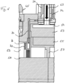
- each individual cutting wheel 40 or a pair of cutting wheels 40 can be connected to a bearing plate 34 with a cutting wheel drive 50, which can have an electric motor 52 designed as a hub motor.
- the Electric motor 52 may comprise an outer ring-shaped stator 53 and a rotor 55 rotatably mounted and driven therein. Via an inner ring-shaped output flange 57, which is in the Figures 5 and 6 As shown, a torque generated by the electric motor 52 can be transmitted to the cutting wheels 40 via a gear 58, which is only indicated schematically, in particular a reduction gear with meshing gear elements.
- an outer ring-shaped cooling channel 54 is arranged on the ring-shaped stator 53 of the electric motor 52, through which a cooling medium, in particular a cooling liquid, can flow around the stator 53 to cool the electric motor 52.
- the cooling channel 54 can preferably be designed with a flat rectangular flow cross-section or channel cross-section in order to achieve the best possible heat transfer to the cooling medium.
- Each electric motor 52 is connected to a supply line 67 and a discharge line 69 for supplying or discharging the cooling medium.
- the supply line 67 and the discharge line 69 extend from the electric motors 52 through the bearing plates 35 upwards to a distribution device 66 on the frame 32.
- the distribution device 66 is connected to the cooling device 61 via the cooling line hoses 62 with a supply line 63 for supplying the cooling medium and a discharge line 64 for discharging the heated cooling medium.
- the distribution device 66 can have control valves 68 shown schematically, which, controlled by a control unit, supply and/or discharge cooling medium to the individual electric motors 52 as required.
- the control valves 68 can be electrically controllable valves, which can in particular be controlled electromagnetically.
- Temperature sensors for directly and/or indirectly detecting the temperature of each electric motor 52 can be arranged at individual points on the electric motor 52 and/or on the cooling circuit 60.
- the at least one temperature sensor is in signal connection with the control unit, which, in accordance with a program specification based on the detected temperature values, controls a coolant pump (not shown), which can in particular also be arranged on the frame 32 of the trench wall cutter 30, and/or the control valves 68 of the distribution device 66 in order to achieve cooling of the individual electric motors 52 as required.
- a transmission cooling line 74 can also be supplied with cooling medium by the distribution device 66.
- the transmission cooling line 74 extends to a heat exchanger 70 in a transmission interior 59 of the transmission 58 for driving the milling wheels 40.
- the heat exchanger 70 which is preferably equipped with heat exchange fins 72, can also cool the transmission oil in the transmission interior 59, which is heated up considerably during milling operation, through the existing cooling circuit 60. This means that an otherwise necessary additional circuit for the transmission oil can be omitted.
Landscapes
- Engineering & Computer Science (AREA)
- Mining & Mineral Resources (AREA)
- Power Engineering (AREA)
- Civil Engineering (AREA)
- General Engineering & Computer Science (AREA)
- Structural Engineering (AREA)
- Mechanical Engineering (AREA)
- Life Sciences & Earth Sciences (AREA)
- General Life Sciences & Earth Sciences (AREA)
- Paleontology (AREA)
- Motor Or Generator Cooling System (AREA)
Priority Applications (1)
| Application Number | Priority Date | Filing Date | Title |
|---|---|---|---|
| EP23170046.9A EP4455407A1 (fr) | 2023-04-26 | 2023-04-26 | Dispositif d'excavation pour la construction de diaphragmes et procédé de réalisation d'une fouille de fondation |
Applications Claiming Priority (1)
| Application Number | Priority Date | Filing Date | Title |
|---|---|---|---|
| EP23170046.9A EP4455407A1 (fr) | 2023-04-26 | 2023-04-26 | Dispositif d'excavation pour la construction de diaphragmes et procédé de réalisation d'une fouille de fondation |
Publications (1)
| Publication Number | Publication Date |
|---|---|
| EP4455407A1 true EP4455407A1 (fr) | 2024-10-30 |
Family
ID=86226990
Family Applications (1)
| Application Number | Title | Priority Date | Filing Date |
|---|---|---|---|
| EP23170046.9A Pending EP4455407A1 (fr) | 2023-04-26 | 2023-04-26 | Dispositif d'excavation pour la construction de diaphragmes et procédé de réalisation d'une fouille de fondation |
Country Status (1)
| Country | Link |
|---|---|
| EP (1) | EP4455407A1 (fr) |
Citations (7)
| Publication number | Priority date | Publication date | Assignee | Title |
|---|---|---|---|---|
| DE3424999A1 (de) | 1984-07-06 | 1986-01-16 | Karl Bauer Spezialtiefbau GmbH & Co KG, 8898 Schrobenhausen | Schlitzwandfraese |
| JPH08270007A (ja) * | 1995-03-31 | 1996-10-15 | Tone Corp | 地中連続壁掘削機 |
| DE102005038267A1 (de) * | 2005-08-12 | 2007-02-15 | Linde Ag | Elektrische Maschine mit innerer Flüssigkeitskühlung |
| DE102008007414A1 (de) * | 2007-02-05 | 2008-08-07 | Ford Global Technologies, LLC, Dearborn | System und Verfahren zum Steuern von Temperatur eines Drehstromgenerators und/oder Motors in einem Fahrzeug |
| EP3467209A1 (fr) | 2017-10-06 | 2019-04-10 | Soilmec S.p.A. | Outil d'excavation pour la construction de diaphragmes et équipement lié |
| CN110858745A (zh) * | 2018-08-24 | 2020-03-03 | 上海中车艾森迪海洋装备有限公司 | 一种用于海底电机的冷却装置及方法 |
| EP3904603A1 (fr) * | 2020-04-29 | 2021-11-03 | BAUER Spezialtiefbau GmbH | Fraise pour parois moulées |
-
2023
- 2023-04-26 EP EP23170046.9A patent/EP4455407A1/fr active Pending
Patent Citations (7)
| Publication number | Priority date | Publication date | Assignee | Title |
|---|---|---|---|---|
| DE3424999A1 (de) | 1984-07-06 | 1986-01-16 | Karl Bauer Spezialtiefbau GmbH & Co KG, 8898 Schrobenhausen | Schlitzwandfraese |
| JPH08270007A (ja) * | 1995-03-31 | 1996-10-15 | Tone Corp | 地中連続壁掘削機 |
| DE102005038267A1 (de) * | 2005-08-12 | 2007-02-15 | Linde Ag | Elektrische Maschine mit innerer Flüssigkeitskühlung |
| DE102008007414A1 (de) * | 2007-02-05 | 2008-08-07 | Ford Global Technologies, LLC, Dearborn | System und Verfahren zum Steuern von Temperatur eines Drehstromgenerators und/oder Motors in einem Fahrzeug |
| EP3467209A1 (fr) | 2017-10-06 | 2019-04-10 | Soilmec S.p.A. | Outil d'excavation pour la construction de diaphragmes et équipement lié |
| CN110858745A (zh) * | 2018-08-24 | 2020-03-03 | 上海中车艾森迪海洋装备有限公司 | 一种用于海底电机的冷却装置及方法 |
| EP3904603A1 (fr) * | 2020-04-29 | 2021-11-03 | BAUER Spezialtiefbau GmbH | Fraise pour parois moulées |
Similar Documents
| Publication | Publication Date | Title |
|---|---|---|
| DE10308538C5 (de) | Verfahren zum Herstellen einer Schlitzwand im Boden, Schlitzwandfräse und Schlitzwandfräsvorrichtung | |
| DE69706729T2 (de) | Wechselgetriebe | |
| DE68911912T2 (de) | Funkenerosionsmaschine. | |
| DE4238564A1 (de) | Elektrowerkzeug mit Absaugung | |
| EP2726314B1 (fr) | Groupe générateur destiné à un véhicule utilitaire agricole ou communal | |
| EP2975208B1 (fr) | Engin et procédé de commande d'un engin | |
| DE112016006959T5 (de) | Getriebe mit variabler drehzahl | |
| DE102010056567A1 (de) | Flüssigkeits-Luft-Kühlsystem | |
| EP4239130B1 (fr) | Fraise à parois moulées et procédé de réalisation d'une tranchée dans le sol | |
| EP0243608A1 (fr) | Dispositif pour former une tranchée substantiellement verticale dans le sol | |
| DE3008828C2 (de) | Mehrfachziehbank zum Ziehen von Draht ohne Drahtschlupf | |
| DE8509777U1 (de) | Werkzeugmaschine zur Fräs- und Drehbearbeitung | |
| EP3901373A1 (fr) | Unité de remplacement destinée au traitement texturant de surface du sol et la machine de construction routière dotée d'une telle unité de remplacement | |
| DE1402924A1 (de) | Einrichtung zum Verhindern oertlicher Waermedehnungen in Maschinenteilen,in denen Hochleistungs-Arbeitsspindeln laufen | |
| EP4455407A1 (fr) | Dispositif d'excavation pour la construction de diaphragmes et procédé de réalisation d'une fouille de fondation | |
| DE29507871U1 (de) | Wälzfräsmaschine | |
| EP3744898B1 (fr) | Groupe de fraisage de machine de traitement du sol interchangeable de manière conforme pourvu d'aérateur de radiateur permettant de refroidir un circuit de consommable fermé | |
| EP1666671A1 (fr) | Fraise pour paroi moulée | |
| EP1273426A1 (fr) | Extrudeuse entraínée directement et méthode d'opération d'une telle extrudeuse | |
| EP0491067B1 (fr) | Procédé pour la limitation d'un glissement | |
| DE4430176A1 (de) | Schneckenextruder | |
| DE102010023024A1 (de) | Selbstfahrender Oberflächenfräser mit fester Lagerung des Fräswalzenantriebs | |
| EP1477633B1 (fr) | Procédé et dispositif pour le travail du sol | |
| CH715468B1 (de) | Doppelseiten-Planschleifmaschine. | |
| DE102012010947A1 (de) | Fräsrotor für eine Baumaschine zur Bodenbearbeitung und Baumaschine mit einem Fräsrotor |
Legal Events
| Date | Code | Title | Description |
|---|---|---|---|
| PUAI | Public reference made under article 153(3) epc to a published international application that has entered the european phase |
Free format text: ORIGINAL CODE: 0009012 |
|
| STAA | Information on the status of an ep patent application or granted ep patent |
Free format text: STATUS: REQUEST FOR EXAMINATION WAS MADE |
|
| 17P | Request for examination filed |
Effective date: 20240328 |
|
| AK | Designated contracting states |
Kind code of ref document: A1 Designated state(s): AL AT BE BG CH CY CZ DE DK EE ES FI FR GB GR HR HU IE IS IT LI LT LU LV MC ME MK MT NL NO PL PT RO RS SE SI SK SM TR |
|
| STAA | Information on the status of an ep patent application or granted ep patent |
Free format text: STATUS: EXAMINATION IS IN PROGRESS |
|
| 17Q | First examination report despatched |
Effective date: 20251103 |