EP3904647A1 - Unité de raccordement pour un chauffage à gaz d'échappement - Google Patents
Unité de raccordement pour un chauffage à gaz d'échappement Download PDFInfo
- Publication number
- EP3904647A1 EP3904647A1 EP21164439.8A EP21164439A EP3904647A1 EP 3904647 A1 EP3904647 A1 EP 3904647A1 EP 21164439 A EP21164439 A EP 21164439A EP 3904647 A1 EP3904647 A1 EP 3904647A1
- Authority
- EP
- European Patent Office
- Prior art keywords
- connection
- area
- holding section
- connection unit
- unit according
- Prior art date
- Legal status (The legal status is an assumption and is not a legal conclusion. Google has not performed a legal analysis and makes no representation as to the accuracy of the status listed.)
- Granted
Links
Images


Classifications
-
- H—ELECTRICITY
- H01—ELECTRIC ELEMENTS
- H01R—ELECTRICALLY-CONDUCTIVE CONNECTIONS; STRUCTURAL ASSOCIATIONS OF A PLURALITY OF MUTUALLY-INSULATED ELECTRICAL CONNECTING ELEMENTS; COUPLING DEVICES; CURRENT COLLECTORS
- H01R13/00—Details of coupling devices of the kinds covered by groups H01R12/70 or H01R24/00 - H01R33/00
- H01R13/62—Means for facilitating engagement or disengagement of coupling parts or for holding them in engagement
- H01R13/629—Additional means for facilitating engagement or disengagement of coupling parts, e.g. aligning or guiding means, levers, gas pressure electrical locking indicators, manufacturing tolerances
-
- F—MECHANICAL ENGINEERING; LIGHTING; HEATING; WEAPONS; BLASTING
- F01—MACHINES OR ENGINES IN GENERAL; ENGINE PLANTS IN GENERAL; STEAM ENGINES
- F01N—GAS-FLOW SILENCERS OR EXHAUST APPARATUS FOR MACHINES OR ENGINES IN GENERAL; GAS-FLOW SILENCERS OR EXHAUST APPARATUS FOR INTERNAL-COMBUSTION ENGINES
- F01N13/00—Exhaust or silencing apparatus characterised by constructional features
- F01N13/14—Exhaust or silencing apparatus characterised by constructional features having thermal insulation
-
- F—MECHANICAL ENGINEERING; LIGHTING; HEATING; WEAPONS; BLASTING
- F01—MACHINES OR ENGINES IN GENERAL; ENGINE PLANTS IN GENERAL; STEAM ENGINES
- F01N—GAS-FLOW SILENCERS OR EXHAUST APPARATUS FOR MACHINES OR ENGINES IN GENERAL; GAS-FLOW SILENCERS OR EXHAUST APPARATUS FOR INTERNAL-COMBUSTION ENGINES
- F01N3/00—Exhaust or silencing apparatus having means for purifying, rendering innocuous, or otherwise treating exhaust
- F01N3/02—Exhaust or silencing apparatus having means for purifying, rendering innocuous, or otherwise treating exhaust for cooling, or for removing solid constituents of, exhaust
- F01N3/021—Exhaust or silencing apparatus having means for purifying, rendering innocuous, or otherwise treating exhaust for cooling, or for removing solid constituents of, exhaust by means of filters
- F01N3/023—Exhaust or silencing apparatus having means for purifying, rendering innocuous, or otherwise treating exhaust for cooling, or for removing solid constituents of, exhaust by means of filters using means for regenerating the filters, e.g. by burning trapped particles
- F01N3/027—Exhaust or silencing apparatus having means for purifying, rendering innocuous, or otherwise treating exhaust for cooling, or for removing solid constituents of, exhaust by means of filters using means for regenerating the filters, e.g. by burning trapped particles using electric or magnetic heating means
-
- F—MECHANICAL ENGINEERING; LIGHTING; HEATING; WEAPONS; BLASTING
- F01—MACHINES OR ENGINES IN GENERAL; ENGINE PLANTS IN GENERAL; STEAM ENGINES
- F01N—GAS-FLOW SILENCERS OR EXHAUST APPARATUS FOR MACHINES OR ENGINES IN GENERAL; GAS-FLOW SILENCERS OR EXHAUST APPARATUS FOR INTERNAL-COMBUSTION ENGINES
- F01N3/00—Exhaust or silencing apparatus having means for purifying, rendering innocuous, or otherwise treating exhaust
- F01N3/08—Exhaust or silencing apparatus having means for purifying, rendering innocuous, or otherwise treating exhaust for rendering innocuous
- F01N3/10—Exhaust or silencing apparatus having means for purifying, rendering innocuous, or otherwise treating exhaust for rendering innocuous by thermal or catalytic conversion of noxious components of exhaust
- F01N3/18—Exhaust or silencing apparatus having means for purifying, rendering innocuous, or otherwise treating exhaust for rendering innocuous by thermal or catalytic conversion of noxious components of exhaust characterised by methods of operation; Control
- F01N3/20—Exhaust or silencing apparatus having means for purifying, rendering innocuous, or otherwise treating exhaust for rendering innocuous by thermal or catalytic conversion of noxious components of exhaust characterised by methods of operation; Control specially adapted for catalytic conversion
- F01N3/2006—Periodically heating or cooling catalytic reactors, e.g. at cold starting or overheating
- F01N3/2013—Periodically heating or cooling catalytic reactors, e.g. at cold starting or overheating using electric or magnetic heating means
-
- H—ELECTRICITY
- H01—ELECTRIC ELEMENTS
- H01R—ELECTRICALLY-CONDUCTIVE CONNECTIONS; STRUCTURAL ASSOCIATIONS OF A PLURALITY OF MUTUALLY-INSULATED ELECTRICAL CONNECTING ELEMENTS; COUPLING DEVICES; CURRENT COLLECTORS
- H01R13/00—Details of coupling devices of the kinds covered by groups H01R12/70 or H01R24/00 - H01R33/00
- H01R13/46—Bases; Cases
- H01R13/52—Dustproof, splashproof, drip-proof, waterproof, or flameproof cases
- H01R13/5219—Sealing means between coupling parts, e.g. interfacial seal
-
- H—ELECTRICITY
- H01—ELECTRIC ELEMENTS
- H01R—ELECTRICALLY-CONDUCTIVE CONNECTIONS; STRUCTURAL ASSOCIATIONS OF A PLURALITY OF MUTUALLY-INSULATED ELECTRICAL CONNECTING ELEMENTS; COUPLING DEVICES; CURRENT COLLECTORS
- H01R13/00—Details of coupling devices of the kinds covered by groups H01R12/70 or H01R24/00 - H01R33/00
- H01R13/62—Means for facilitating engagement or disengagement of coupling parts or for holding them in engagement
- H01R13/639—Additional means for holding or locking coupling parts together, after engagement, e.g. separate keylock, retainer strap
-
- H—ELECTRICITY
- H05—ELECTRIC TECHNIQUES NOT OTHERWISE PROVIDED FOR
- H05B—ELECTRIC HEATING; ELECTRIC LIGHT SOURCES NOT OTHERWISE PROVIDED FOR; CIRCUIT ARRANGEMENTS FOR ELECTRIC LIGHT SOURCES, IN GENERAL
- H05B3/00—Ohmic-resistance heating
- H05B3/02—Details
- H05B3/06—Heater elements structurally combined with coupling elements or holders
- H05B3/08—Heater elements structurally combined with coupling elements or holders having electric connections specially adapted for high temperatures
-
- F—MECHANICAL ENGINEERING; LIGHTING; HEATING; WEAPONS; BLASTING
- F01—MACHINES OR ENGINES IN GENERAL; ENGINE PLANTS IN GENERAL; STEAM ENGINES
- F01N—GAS-FLOW SILENCERS OR EXHAUST APPARATUS FOR MACHINES OR ENGINES IN GENERAL; GAS-FLOW SILENCERS OR EXHAUST APPARATUS FOR INTERNAL-COMBUSTION ENGINES
- F01N2240/00—Combination or association of two or more different exhaust treating devices, or of at least one such device with an auxiliary device, not covered by indexing codes F01N2230/00 or F01N2250/00, one of the devices being
- F01N2240/16—Combination or association of two or more different exhaust treating devices, or of at least one such device with an auxiliary device, not covered by indexing codes F01N2230/00 or F01N2250/00, one of the devices being an electric heater, i.e. a resistance heater
-
- H—ELECTRICITY
- H05—ELECTRIC TECHNIQUES NOT OTHERWISE PROVIDED FOR
- H05B—ELECTRIC HEATING; ELECTRIC LIGHT SOURCES NOT OTHERWISE PROVIDED FOR; CIRCUIT ARRANGEMENTS FOR ELECTRIC LIGHT SOURCES, IN GENERAL
- H05B2203/00—Aspects relating to Ohmic resistive heating covered by group H05B3/00
- H05B2203/022—Heaters specially adapted for heating gaseous material
Definitions
- the present invention relates to a connection unit for an exhaust gas heater in an exhaust system of an internal combustion engine.
- the exhaust gas heater comprises a plate-like carrier carried in the exhaust gas routing component and a spiral-like wound heating conductor on one side of the plate-like carrier.
- the two connection ends of the heating conductor must be connected to the respective electrical supply lines.
- the object of the present invention is to provide a connection unit for an exhaust gas heater in an exhaust system of an internal combustion engine, with which an electrical connection to a heating conductor of the exhaust gas heater arranged inside an exhaust gas routing component of an exhaust system can be established in a simple and reliable manner.
- connection unit of this type With a connection unit of this type, with a simple structure, the possibility is created of making electrical contact with a heating conductor in the interior of an exhaust gas routing component, but at the same time making electrical contact with this or the connection element to isolate with respect to the exhaust gas routing component, which is generally made of sheet metal, and to establish a gas-tight connection between the connection element and the exhaust gas routing component.
- the inner connection area be provided at a first longitudinal end of the terminating element and the external connection area at a second longitudinal end of the terminating element is provided, and / or that the external connection area comprises an external thread, and / or that the internal connection area comprises a heating conductor receiving opening.
- connection element between the inner connection area and the outer connection area comprises an insulating assembly support area held on the carrier assembly by means of the insulating assembly.
- the insulation assembly support area comprises a first holding section that widens radially in the direction away from the inner connection area towards the outer connection area and a second holding section that widens radially in the direction away from the outer connection area towards the first holding section.
- first holding section and the second holding section adjoin one another in their axial end regions with maximum radial dimensions, and / or that the first holding section and / or the second holding section widen substantially conically and radially is trained.
- the insulating arrangement can comprise at least one insulating sleeve surrounding the connection element.
- the insulating arrangement is preferably designed in such a way that it comprises a first insulating sleeve in association with the first holding section and comprises a second insulating sleeve in association with the second holding section.
- the first insulating sleeve can be designed to expand radially in the direction of the second insulating sleeve on an inner circumferential area and an outer circumferential area
- the second insulating sleeve can be designed on one Inner circumferential area and an outer circumferential area can be designed to expand radially in the direction of the first insulating sleeve.
- first insulating sleeve and / or the second insulating sleeve are designed to widen substantially conically and radially at their inner circumferential area and their outer circumferential area, preferably in adaptation to the shape of the connection element.
- the at least one insulating sleeve is constructed with ceramic material or mica material, a mechanically stable, electrically insulating and also a gas-tight connection ensuring a connection between the connection element and the carrier arrangement is achieved.
- the carrier arrangement can comprise a first carrier element to be fixed to an exhaust system and a second carrier element which clamps the connection element together with the first carrier element.
- the first carrier element in association with the first holding portion can comprise a first carrying portion widening radially in the direction of the second carrier element
- the second carrier element can in association with the second holding section comprise a second support section which widens radially in the direction of the first support element.
- the first support section and / or the second support section are designed to widen substantially conically and radially.
- first support section surrounds the first holding section with the first insulating sleeve interposed
- second support section surrounds the second holding section with the second insulating sleeve interposed
- the first carrier element be coupled to the second carrier element such that it can be axially displaced with respect to one another.
- This can be implemented, for example, in that the first carrier element is coupled to the second carrier element by thread engagement.
- the invention also relates to an exhaust system for an internal combustion engine, comprising an exhaust gas routing component, an exhaust gas heater with a heating conductor arranged in the exhaust gas routing component and, in association with at least one, preferably each connection end of the heating conductor, a connection unit constructed according to the invention.
- the exhaust gas heater 10 comprises a disk-like, for example conically shaped, carrier 12 constructed, for example, from sheet metal material, which is integrated into a tubular exhaust gas routing component 14 of an exhaust system generally designated 16.
- a spiral-like wound heating area 18 of a heating conductor, generally designated 20, is provided on one side of the carrier 12.
- the heating area 18 of the heating conductor 20, which is at least partially non-electrically insulated and held on the carrier 12, heats up when an electrical current is applied and thereby heats the exhaust gas to be flowed, for example, towards a catalytic converter arrangement or another exhaust gas treatment unit.
- connection assembly 22 shown in principle is provided.
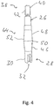
- the connector assembly 22 according to the principles of the present invention can be described in two ways below with reference to FIG Figs. 2 to 4 include connection units 24 described in detail.
- Each of the connection units 24 is electrically conductively connected to one of the two connection ends of the heating conductor 20 and provides the possibility of establishing a connection to a respective electrical supply line outside the exhaust gas routing component.
- connection unit 24 shown comprises, as a central component, a connection element 26 made, for example, of steel material and thus electrically conductive.
- the inner connection area 30 can, for example, comprise a heating conductor receiving opening 32 and can be slotted, that is to say designed with two grooves 34, for example.
- a connection end 36 of the heating conductor 20 is pushed into the heating conductor receiving opening 32.
- the connection element 26 can then be squeezed together, that is to say compressed, in its inner connection area 30, as a result of which the connection end 36 of the heating conductor 20 is firmly anchored on the connection element 26.
- this fixed connection can be achieved by material bonding, such as. B. welding or soldering or gluing take place.
- connection element 26 At its second longitudinal end 38 in the direction of the connection element longitudinal axis L, the connection element 26 has an external connection region 40.
- the external connection area 40 can be constructed, for example, with an external thread 42, onto which a nut realizing a fixed connection of an electrical supply line can be screwed.
- connection element 26 Between the inner connection area 30 and the outer connection area 42, the connection element 26 has an insulating arrangement support area generally designated 44.
- the connection element 26 has two holding sections 46, 48 that expand axially towards one another or away from a respective closer longitudinal end 28, 38 with respect to the connection element longitudinal axis L.
- the two holding sections 46, 48 are designed with a conical outer circumferential contour and directly adjoin one another in their end regions 50, 52 with maximum outer dimensions.
- a cylindrical section of the connecting element 26 could be positioned between the end area 50 with the maximum outer dimension of the first holding section 46 and the end area 52 with the maximum radial dimension of the second holding section 48, that is to say a Section in which the connection element 26 has an approximately constant radial dimension.
- the carrier arrangement 54 comprises a sleeve-like or sleeve-like first carrier element 56 made of metal material, for example steel material, which is inserted into an opening 58 of the exhaust gas routing component 14 and is fixed to it in a stable and gas-tight manner by a weld 60.
- the carrier arrangement 54 furthermore comprises a second carrier element 62 embodied in the manner of a sleeve or sleeve, which is inserted into the end of the first carrier element 56 lying outside the exhaust gas routing component 14 and connected to it by thread engagement.
- the first carrier element 56 has an internal thread 64 essentially in its length region positioned outside the exhaust gas routing component 14, while the second carrier element 62 can be designed with an external thread 66 in its length region to be positioned so as to engage in the first carrier element 56.
- the first support element 56 has a radially expanding first support section 68.
- the first support section 68 can be shaped complementarily to the first holding section 56, that is to say for example, at least in the greater part of its longitudinal extent, can be designed to widen conically. In the assembled state, the first support section 68 essentially surrounds the first holding section 46.
- the second support element 62 has a second support section 70 adapted to the second holding section 48. This is according to the shape of the The second holding section 48 is designed to expand conically and radially and surrounds the second holding section 48.
- an insulating arrangement generally designated 72 is provided. This comprises a first insulating sleeve 74 in association with the first holding section 46 or the first support section 68 and a second insulating sleeve 76 in association with the second support section 48 or the second holding section 70.
- the two insulating sleeves 74, 76 are designed to expand radially towards one another in their inner circumferential areas and their outer circumferential areas, in particular also to expand conically and radially.
- the first insulating sleeve 74 can have, for example, in its end region close to the first longitudinal end 28 of the connection element 26, an approximately cylindrical end section which surrounds the first longitudinal end 28 adjoining the first holding section 46, which can also have a cylindrical outer circumferential contour, and on the outside by a correspondingly cylindrically shaped axial end region of the first support section 68 is surrounded.
- connection element 26 is supported radially on the one hand with respect to the first carrier element 56 and the second carrier element 62, and is due to the shape of the two holding sections expanding radially towards one another 46, 68 and the complementary shape of the two support sections 68, 70 are also held positively on the support arrangement 54 in the axial direction.
- the two insulating sleeves 74, 76 on the inner circumferential area is adapted to the shape of the two holding sections 46, 48 and on the outer circumferential area is adapted to the shape of the two carrying sections 68, 70
- the two insulating sleeves 74 made of ceramic material or mica material, for example , 76 not only provide electrical insulation of the connection element 26 with respect to the carrier arrangement 54, but also realize due to the exact Fit also a gas-tight connection between the connection element 26 and the carrier arrangement 54.
- the stable mounting is achieved or supported in particular by the fact that after the insertion of the connection element 26 with the interposition of the first insulating sleeve 74 in the first carrier element 56 and the application of the second insulating sleeve 76 to the second holding section 48, the second carrier element 62 is pushed onto the connection element 26 and is screwed into the first carrier element 56.
- the second carrier element 62 moves axially towards the inner connection region 30 of the connection element 26 and thus clamps the connection element 26 in a form-fitting, stable manner in the carrier arrangement 54.
- the second carrier element 26 can, for example, by material bonding, such as. B. gluing or welding, are connected to the first carrier element 56 in order to prevent this state from being released.
Landscapes
- Engineering & Computer Science (AREA)
- Chemical & Material Sciences (AREA)
- Combustion & Propulsion (AREA)
- Mechanical Engineering (AREA)
- General Engineering & Computer Science (AREA)
- Chemical Kinetics & Catalysis (AREA)
- Health & Medical Sciences (AREA)
- Toxicology (AREA)
- Exhaust Gas After Treatment (AREA)
- Exhaust Silencers (AREA)
Applications Claiming Priority (1)
| Application Number | Priority Date | Filing Date | Title |
|---|---|---|---|
| DE102020111428.1A DE102020111428A1 (de) | 2020-04-27 | 2020-04-27 | Anschlusseinheit für einen Abgasheizer |
Publications (2)
| Publication Number | Publication Date |
|---|---|
| EP3904647A1 true EP3904647A1 (fr) | 2021-11-03 |
| EP3904647B1 EP3904647B1 (fr) | 2024-02-14 |
Family
ID=75203093
Family Applications (1)
| Application Number | Title | Priority Date | Filing Date |
|---|---|---|---|
| EP21164439.8A Active EP3904647B1 (fr) | 2020-04-27 | 2021-03-24 | Unité de raccordement pour un chauffage à gaz d'échappement |
Country Status (4)
| Country | Link |
|---|---|
| US (1) | US11486286B2 (fr) |
| EP (1) | EP3904647B1 (fr) |
| CN (1) | CN113644491B (fr) |
| DE (1) | DE102020111428A1 (fr) |
Cited By (1)
| Publication number | Priority date | Publication date | Assignee | Title |
|---|---|---|---|---|
| WO2024017690A1 (fr) * | 2022-07-21 | 2024-01-25 | Vitesco Technologies GmbH | Traversée électrique segmentée |
Families Citing this family (5)
| Publication number | Priority date | Publication date | Assignee | Title |
|---|---|---|---|---|
| FR3108677B1 (fr) * | 2020-03-30 | 2022-05-27 | Faurecia Systemes Dechappement | Dispositif de chauffage de gaz d’échappement, ligne d’échappement et véhicule associés |
| DE102021116420A1 (de) * | 2021-06-25 | 2022-12-29 | Purem GmbH | Verbindungsanordnung |
| CA3228841A1 (fr) * | 2021-08-13 | 2023-02-16 | Saban Akyildiz | Systeme d'echappement et ses composants |
| DE102022105603A1 (de) * | 2022-03-10 | 2023-09-14 | Purem GmbH | Abgasbehandlungsanordnung |
| FR3133949B1 (fr) * | 2022-03-22 | 2024-07-26 | Faurecia Systemes Dechappement | Connecteur électrique |
Citations (3)
| Publication number | Priority date | Publication date | Assignee | Title |
|---|---|---|---|---|
| EP0716558A2 (fr) * | 1994-12-07 | 1996-06-12 | Ngk Insulators, Ltd. | Structure d'électrode et élément chauffant électrique le comprenant |
| US5670746A (en) * | 1994-07-29 | 1997-09-23 | Ngk Insulators, Ltd. | Structure of electrode unit |
| WO2020203859A1 (fr) * | 2019-04-04 | 2020-10-08 | 日本特殊陶業株式会社 | Dispositif de chauffage de gaz d'échappement |
Family Cites Families (17)
| Publication number | Priority date | Publication date | Assignee | Title |
|---|---|---|---|---|
| JP2990797B2 (ja) * | 1990-11-30 | 1999-12-13 | 株式会社デンソー | ハニカムヒータ |
| US5571485A (en) * | 1994-07-29 | 1996-11-05 | W. R. Grace & Co.-Conn. | Combined electrically heatable converter body |
| JP3494498B2 (ja) * | 1995-04-17 | 2004-02-09 | 日本碍子株式会社 | 電極構造および通電発熱式ヒーター |
| JPH11257058A (ja) * | 1998-03-12 | 1999-09-21 | Honda Motor Co Ltd | 排気ガス浄化触媒コンバータ加熱装置 |
| GB0301164D0 (en) * | 2003-01-18 | 2003-02-19 | Ceramaspeed Ltd | Temperature-responsive device |
| GB0316627D0 (en) * | 2003-07-16 | 2003-08-20 | Ceramaspeed Ltd | Radiant electric heater |
| DE102009005481B3 (de) * | 2009-01-21 | 2010-04-08 | Bleckmann Gmbh & Co. Kg | Verbindungselement für Heizwendel für Rohrheizkörper sowie Herstellungsverfahren hierfür |
| RU2595463C2 (ru) * | 2012-01-13 | 2016-08-27 | Эмитек Гезельшафт Фюр Эмиссионстехнологи Мбх | Электрически обогреваемое сотовое тело с несколькими электрически соединенными с соединительным штырьком слоями листового металла |
| DE102012005786A1 (de) * | 2012-03-21 | 2013-09-26 | Emitec Gesellschaft Für Emissionstechnologie Mbh | Verdrehsicherer elektrischer Anschluss, insbesondere für einen elektrisch beheizbaren Wabenkörper |
| ES2728255T3 (es) * | 2012-12-18 | 2019-10-23 | Watlow Electric Mfg | Aparato de calefacción de gas de escape mejorado y procedimiento de calefacción |
| DE102015003579A1 (de) * | 2015-03-19 | 2016-09-22 | Kathrein-Werke Kg | HF-Steckverbinder zur lotfreien Kontaktierung eines Koaxialkabels |
| DE202015103787U1 (de) * | 2015-07-17 | 2015-08-06 | Türk & Hillinger GmbH | Gaskanal mit beheizter poröser Metallstruktur |
| DE102015111689C5 (de) * | 2015-07-17 | 2022-09-01 | Türk & Hillinger GmbH | Elektrisch beheizbarer Katalysator und Verfahren zu dessen Herstellung |
| DE102015112286A1 (de) * | 2015-07-28 | 2017-02-02 | R. Stahl Schaltgeräte GmbH | Explosionsgeschützte Anordnung zur Bolzendurchführung und Verfahren zu deren Herstellung |
| DE102016209282B4 (de) * | 2016-05-30 | 2023-01-12 | Vitesco Technologies GmbH | Elektrischer Anschluss, insbesondere für einen elektrisch beheizbaren Wabenkörper |
| DE102016215806B4 (de) * | 2016-08-23 | 2024-01-04 | Volkswagen Aktiengesellschaft | Rückenlehnenanordnung für ein Kraftfahrzeug sowie Kraftfahrzeug |
| DE102019131556A1 (de) | 2019-11-22 | 2021-05-27 | Eberspächer Exhaust Technology GmbH | Abgasheizer |
-
2020
- 2020-04-27 DE DE102020111428.1A patent/DE102020111428A1/de active Pending
-
2021
- 2021-03-24 EP EP21164439.8A patent/EP3904647B1/fr active Active
- 2021-04-27 US US17/241,423 patent/US11486286B2/en active Active
- 2021-04-27 CN CN202110457144.XA patent/CN113644491B/zh active Active
Patent Citations (3)
| Publication number | Priority date | Publication date | Assignee | Title |
|---|---|---|---|---|
| US5670746A (en) * | 1994-07-29 | 1997-09-23 | Ngk Insulators, Ltd. | Structure of electrode unit |
| EP0716558A2 (fr) * | 1994-12-07 | 1996-06-12 | Ngk Insulators, Ltd. | Structure d'électrode et élément chauffant électrique le comprenant |
| WO2020203859A1 (fr) * | 2019-04-04 | 2020-10-08 | 日本特殊陶業株式会社 | Dispositif de chauffage de gaz d'échappement |
Cited By (1)
| Publication number | Priority date | Publication date | Assignee | Title |
|---|---|---|---|---|
| WO2024017690A1 (fr) * | 2022-07-21 | 2024-01-25 | Vitesco Technologies GmbH | Traversée électrique segmentée |
Also Published As
| Publication number | Publication date |
|---|---|
| US20210332728A1 (en) | 2021-10-28 |
| EP3904647B1 (fr) | 2024-02-14 |
| CN113644491A (zh) | 2021-11-12 |
| DE102020111428A1 (de) | 2021-10-28 |
| CN113644491B (zh) | 2024-04-12 |
| US11486286B2 (en) | 2022-11-01 |
Similar Documents
| Publication | Publication Date | Title |
|---|---|---|
| EP3904647B1 (fr) | Unité de raccordement pour un chauffage à gaz d'échappement | |
| EP3022804B1 (fr) | Dispositif de mise en contact électrique d'un blindage de câble électrique avec un boîtier, et câble électrique préfabriqué | |
| DE102021109667A1 (de) | Steckverbinder mit Schraubverbindung | |
| WO2018046994A1 (fr) | Élément de contact électriquement conducteur pour connecteur électrique | |
| EP0444044A1 (fr) | Systeme de bague collectrice. | |
| DE102019121382A1 (de) | Abgasbehandlungseinrichtung und Fahrzeug | |
| EP3363064B1 (fr) | Pôle de batterie et unité de contact électrique pour établir une connexion électrique entre un pôle de batterie et le système électrique d'un véhicule | |
| EP2360804B1 (fr) | Agencement destiné à connecter deux câbles d'énergie | |
| EP4141229B1 (fr) | Chauffage à gaz d'échappement et procédé de fabrication d'un chauffage à gaz d'échappement | |
| EP4174295B1 (fr) | Broche de raccordement | |
| DE3306436C2 (de) | Elektrischer Steckverbinder für Koaxialkabel | |
| EP3320547B1 (fr) | Électrode en forme de jante et ensemble enroulement d'un transformateur de mesure | |
| DE202018006090U1 (de) | Verbindungsbauteil zur Verbindung von elektrischen Leitern einer hairpin-Wicklung eines Stator einer Elektromaschine | |
| WO2018083295A1 (fr) | Système de ligne électrique blindé et boîtier de blindage | |
| DE102020116831A1 (de) | An einem langgestreckten leitfähigen Element angebrachter elektrischer Verbinder, insbesondere für eine Abgasreinigungsvorrichtung | |
| DE102022111864B4 (de) | Heizvorrichtung | |
| EP3574509B1 (fr) | Dispositif pour relier des tubes de blindage d'un appareil à haute tension | |
| WO2016096245A1 (fr) | Étanchéité aux milieux d'une zone de passage entre une zone humide et une zone sèche | |
| WO2019025023A1 (fr) | Traversée enfichable | |
| EP4108891B1 (fr) | Dispositif de chauffage de gaz d'échappement doté d'un agencement de raccordement | |
| EP0696080A1 (fr) | Procédé de raccordement électrique de deux câbles électriques | |
| DE102021208621B4 (de) | Segmentierte elektrische Durchführung | |
| DE2936616A1 (de) | Anschlusseinrichtung fuer koaxialkbel | |
| EP4198273B1 (fr) | Dispositif de chauffage de gaz d'échappement | |
| DE102019110359A1 (de) | Abgasbehandlungseinrichtung und Fahrzeug |
Legal Events
| Date | Code | Title | Description |
|---|---|---|---|
| PUAI | Public reference made under article 153(3) epc to a published international application that has entered the european phase |
Free format text: ORIGINAL CODE: 0009012 |
|
| STAA | Information on the status of an ep patent application or granted ep patent |
Free format text: STATUS: THE APPLICATION HAS BEEN PUBLISHED |
|
| AK | Designated contracting states |
Kind code of ref document: A1 Designated state(s): AL AT BE BG CH CY CZ DE DK EE ES FI FR GB GR HR HU IE IS IT LI LT LU LV MC MK MT NL NO PL PT RO RS SE SI SK SM TR |
|
| B565 | Issuance of search results under rule 164(2) epc |
Effective date: 20210917 |
|
| STAA | Information on the status of an ep patent application or granted ep patent |
Free format text: STATUS: REQUEST FOR EXAMINATION WAS MADE |
|
| 17P | Request for examination filed |
Effective date: 20220210 |
|
| RBV | Designated contracting states (corrected) |
Designated state(s): AL AT BE BG CH CY CZ DE DK EE ES FI FR GB GR HR HU IE IS IT LI LT LU LV MC MK MT NL NO PL PT RO RS SE SI SK SM TR |
|
| STAA | Information on the status of an ep patent application or granted ep patent |
Free format text: STATUS: EXAMINATION IS IN PROGRESS |
|
| 17Q | First examination report despatched |
Effective date: 20220603 |
|
| GRAP | Despatch of communication of intention to grant a patent |
Free format text: ORIGINAL CODE: EPIDOSNIGR1 |
|
| STAA | Information on the status of an ep patent application or granted ep patent |
Free format text: STATUS: GRANT OF PATENT IS INTENDED |
|
| INTG | Intention to grant announced |
Effective date: 20231123 |
|
| GRAS | Grant fee paid |
Free format text: ORIGINAL CODE: EPIDOSNIGR3 |
|
| GRAA | (expected) grant |
Free format text: ORIGINAL CODE: 0009210 |
|
| STAA | Information on the status of an ep patent application or granted ep patent |
Free format text: STATUS: THE PATENT HAS BEEN GRANTED |
|
| AK | Designated contracting states |
Kind code of ref document: B1 Designated state(s): AL AT BE BG CH CY CZ DE DK EE ES FI FR GB GR HR HU IE IS IT LI LT LU LV MC MK MT NL NO PL PT RO RS SE SI SK SM TR |
|
| REG | Reference to a national code |
Ref country code: GB Ref legal event code: FG4D Free format text: NOT ENGLISH |
|
| REG | Reference to a national code |
Ref country code: CH Ref legal event code: EP |
|
| REG | Reference to a national code |
Ref country code: DE Ref legal event code: R096 Ref document number: 502021002655 Country of ref document: DE |
|
| REG | Reference to a national code |
Ref country code: IE Ref legal event code: FG4D Free format text: LANGUAGE OF EP DOCUMENT: GERMAN |
|
| REG | Reference to a national code |
Ref country code: LT Ref legal event code: MG9D |
|
| REG | Reference to a national code |
Ref country code: NL Ref legal event code: MP Effective date: 20240214 |
|
| PG25 | Lapsed in a contracting state [announced via postgrant information from national office to epo] |
Ref country code: IS Free format text: LAPSE BECAUSE OF FAILURE TO SUBMIT A TRANSLATION OF THE DESCRIPTION OR TO PAY THE FEE WITHIN THE PRESCRIBED TIME-LIMIT Effective date: 20240614 |
|
| PG25 | Lapsed in a contracting state [announced via postgrant information from national office to epo] |
Ref country code: LT Free format text: LAPSE BECAUSE OF FAILURE TO SUBMIT A TRANSLATION OF THE DESCRIPTION OR TO PAY THE FEE WITHIN THE PRESCRIBED TIME-LIMIT Effective date: 20240214 |
|
| PG25 | Lapsed in a contracting state [announced via postgrant information from national office to epo] |
Ref country code: GR Free format text: LAPSE BECAUSE OF FAILURE TO SUBMIT A TRANSLATION OF THE DESCRIPTION OR TO PAY THE FEE WITHIN THE PRESCRIBED TIME-LIMIT Effective date: 20240515 |
|
| PG25 | Lapsed in a contracting state [announced via postgrant information from national office to epo] |
Ref country code: NL Free format text: LAPSE BECAUSE OF FAILURE TO SUBMIT A TRANSLATION OF THE DESCRIPTION OR TO PAY THE FEE WITHIN THE PRESCRIBED TIME-LIMIT Effective date: 20240214 Ref country code: RS Free format text: LAPSE BECAUSE OF FAILURE TO SUBMIT A TRANSLATION OF THE DESCRIPTION OR TO PAY THE FEE WITHIN THE PRESCRIBED TIME-LIMIT Effective date: 20240514 Ref country code: HR Free format text: LAPSE BECAUSE OF FAILURE TO SUBMIT A TRANSLATION OF THE DESCRIPTION OR TO PAY THE FEE WITHIN THE PRESCRIBED TIME-LIMIT Effective date: 20240214 |
|
| PG25 | Lapsed in a contracting state [announced via postgrant information from national office to epo] |
Ref country code: ES Free format text: LAPSE BECAUSE OF FAILURE TO SUBMIT A TRANSLATION OF THE DESCRIPTION OR TO PAY THE FEE WITHIN THE PRESCRIBED TIME-LIMIT Effective date: 20240214 |
|
| PG25 | Lapsed in a contracting state [announced via postgrant information from national office to epo] |
Ref country code: RS Free format text: LAPSE BECAUSE OF FAILURE TO SUBMIT A TRANSLATION OF THE DESCRIPTION OR TO PAY THE FEE WITHIN THE PRESCRIBED TIME-LIMIT Effective date: 20240514 Ref country code: NO Free format text: LAPSE BECAUSE OF FAILURE TO SUBMIT A TRANSLATION OF THE DESCRIPTION OR TO PAY THE FEE WITHIN THE PRESCRIBED TIME-LIMIT Effective date: 20240514 Ref country code: NL Free format text: LAPSE BECAUSE OF FAILURE TO SUBMIT A TRANSLATION OF THE DESCRIPTION OR TO PAY THE FEE WITHIN THE PRESCRIBED TIME-LIMIT Effective date: 20240214 Ref country code: LT Free format text: LAPSE BECAUSE OF FAILURE TO SUBMIT A TRANSLATION OF THE DESCRIPTION OR TO PAY THE FEE WITHIN THE PRESCRIBED TIME-LIMIT Effective date: 20240214 Ref country code: IS Free format text: LAPSE BECAUSE OF FAILURE TO SUBMIT A TRANSLATION OF THE DESCRIPTION OR TO PAY THE FEE WITHIN THE PRESCRIBED TIME-LIMIT Effective date: 20240614 Ref country code: HR Free format text: LAPSE BECAUSE OF FAILURE TO SUBMIT A TRANSLATION OF THE DESCRIPTION OR TO PAY THE FEE WITHIN THE PRESCRIBED TIME-LIMIT Effective date: 20240214 Ref country code: GR Free format text: LAPSE BECAUSE OF FAILURE TO SUBMIT A TRANSLATION OF THE DESCRIPTION OR TO PAY THE FEE WITHIN THE PRESCRIBED TIME-LIMIT Effective date: 20240515 Ref country code: FI Free format text: LAPSE BECAUSE OF FAILURE TO SUBMIT A TRANSLATION OF THE DESCRIPTION OR TO PAY THE FEE WITHIN THE PRESCRIBED TIME-LIMIT Effective date: 20240214 Ref country code: ES Free format text: LAPSE BECAUSE OF FAILURE TO SUBMIT A TRANSLATION OF THE DESCRIPTION OR TO PAY THE FEE WITHIN THE PRESCRIBED TIME-LIMIT Effective date: 20240214 Ref country code: BG Free format text: LAPSE BECAUSE OF FAILURE TO SUBMIT A TRANSLATION OF THE DESCRIPTION OR TO PAY THE FEE WITHIN THE PRESCRIBED TIME-LIMIT Effective date: 20240214 |
|
| PG25 | Lapsed in a contracting state [announced via postgrant information from national office to epo] |
Ref country code: PT Free format text: LAPSE BECAUSE OF FAILURE TO SUBMIT A TRANSLATION OF THE DESCRIPTION OR TO PAY THE FEE WITHIN THE PRESCRIBED TIME-LIMIT Effective date: 20240614 Ref country code: PL Free format text: LAPSE BECAUSE OF FAILURE TO SUBMIT A TRANSLATION OF THE DESCRIPTION OR TO PAY THE FEE WITHIN THE PRESCRIBED TIME-LIMIT Effective date: 20240214 |
|
| PG25 | Lapsed in a contracting state [announced via postgrant information from national office to epo] |
Ref country code: SE Free format text: LAPSE BECAUSE OF FAILURE TO SUBMIT A TRANSLATION OF THE DESCRIPTION OR TO PAY THE FEE WITHIN THE PRESCRIBED TIME-LIMIT Effective date: 20240214 Ref country code: PT Free format text: LAPSE BECAUSE OF FAILURE TO SUBMIT A TRANSLATION OF THE DESCRIPTION OR TO PAY THE FEE WITHIN THE PRESCRIBED TIME-LIMIT Effective date: 20240614 Ref country code: PL Free format text: LAPSE BECAUSE OF FAILURE TO SUBMIT A TRANSLATION OF THE DESCRIPTION OR TO PAY THE FEE WITHIN THE PRESCRIBED TIME-LIMIT Effective date: 20240214 Ref country code: LV Free format text: LAPSE BECAUSE OF FAILURE TO SUBMIT A TRANSLATION OF THE DESCRIPTION OR TO PAY THE FEE WITHIN THE PRESCRIBED TIME-LIMIT Effective date: 20240214 |
|
| PG25 | Lapsed in a contracting state [announced via postgrant information from national office to epo] |
Ref country code: DK Free format text: LAPSE BECAUSE OF FAILURE TO SUBMIT A TRANSLATION OF THE DESCRIPTION OR TO PAY THE FEE WITHIN THE PRESCRIBED TIME-LIMIT Effective date: 20240214 |
|
| PG25 | Lapsed in a contracting state [announced via postgrant information from national office to epo] |
Ref country code: SM Free format text: LAPSE BECAUSE OF FAILURE TO SUBMIT A TRANSLATION OF THE DESCRIPTION OR TO PAY THE FEE WITHIN THE PRESCRIBED TIME-LIMIT Effective date: 20240214 |
|
| PG25 | Lapsed in a contracting state [announced via postgrant information from national office to epo] |
Ref country code: CZ Free format text: LAPSE BECAUSE OF FAILURE TO SUBMIT A TRANSLATION OF THE DESCRIPTION OR TO PAY THE FEE WITHIN THE PRESCRIBED TIME-LIMIT Effective date: 20240214 Ref country code: EE Free format text: LAPSE BECAUSE OF FAILURE TO SUBMIT A TRANSLATION OF THE DESCRIPTION OR TO PAY THE FEE WITHIN THE PRESCRIBED TIME-LIMIT Effective date: 20240214 |
|
| PG25 | Lapsed in a contracting state [announced via postgrant information from national office to epo] |
Ref country code: SK Free format text: LAPSE BECAUSE OF FAILURE TO SUBMIT A TRANSLATION OF THE DESCRIPTION OR TO PAY THE FEE WITHIN THE PRESCRIBED TIME-LIMIT Effective date: 20240214 |
|
| PG25 | Lapsed in a contracting state [announced via postgrant information from national office to epo] |
Ref country code: SM Free format text: LAPSE BECAUSE OF FAILURE TO SUBMIT A TRANSLATION OF THE DESCRIPTION OR TO PAY THE FEE WITHIN THE PRESCRIBED TIME-LIMIT Effective date: 20240214 Ref country code: SK Free format text: LAPSE BECAUSE OF FAILURE TO SUBMIT A TRANSLATION OF THE DESCRIPTION OR TO PAY THE FEE WITHIN THE PRESCRIBED TIME-LIMIT Effective date: 20240214 Ref country code: RO Free format text: LAPSE BECAUSE OF FAILURE TO SUBMIT A TRANSLATION OF THE DESCRIPTION OR TO PAY THE FEE WITHIN THE PRESCRIBED TIME-LIMIT Effective date: 20240214 Ref country code: EE Free format text: LAPSE BECAUSE OF FAILURE TO SUBMIT A TRANSLATION OF THE DESCRIPTION OR TO PAY THE FEE WITHIN THE PRESCRIBED TIME-LIMIT Effective date: 20240214 Ref country code: DK Free format text: LAPSE BECAUSE OF FAILURE TO SUBMIT A TRANSLATION OF THE DESCRIPTION OR TO PAY THE FEE WITHIN THE PRESCRIBED TIME-LIMIT Effective date: 20240214 Ref country code: CZ Free format text: LAPSE BECAUSE OF FAILURE TO SUBMIT A TRANSLATION OF THE DESCRIPTION OR TO PAY THE FEE WITHIN THE PRESCRIBED TIME-LIMIT Effective date: 20240214 |
|
| REG | Reference to a national code |
Ref country code: CH Ref legal event code: PL |
|
| REG | Reference to a national code |
Ref country code: DE Ref legal event code: R097 Ref document number: 502021002655 Country of ref document: DE |
|
| PG25 | Lapsed in a contracting state [announced via postgrant information from national office to epo] |
Ref country code: LU Free format text: LAPSE BECAUSE OF NON-PAYMENT OF DUE FEES Effective date: 20240324 |
|
| PG25 | Lapsed in a contracting state [announced via postgrant information from national office to epo] |
Ref country code: MC Free format text: LAPSE BECAUSE OF FAILURE TO SUBMIT A TRANSLATION OF THE DESCRIPTION OR TO PAY THE FEE WITHIN THE PRESCRIBED TIME-LIMIT Effective date: 20240214 |
|
| PG25 | Lapsed in a contracting state [announced via postgrant information from national office to epo] |
Ref country code: MC Free format text: LAPSE BECAUSE OF FAILURE TO SUBMIT A TRANSLATION OF THE DESCRIPTION OR TO PAY THE FEE WITHIN THE PRESCRIBED TIME-LIMIT Effective date: 20240214 Ref country code: LU Free format text: LAPSE BECAUSE OF NON-PAYMENT OF DUE FEES Effective date: 20240324 |
|
| PG25 | Lapsed in a contracting state [announced via postgrant information from national office to epo] |
Ref country code: IT Free format text: LAPSE BECAUSE OF FAILURE TO SUBMIT A TRANSLATION OF THE DESCRIPTION OR TO PAY THE FEE WITHIN THE PRESCRIBED TIME-LIMIT Effective date: 20240214 |
|
| REG | Reference to a national code |
Ref country code: BE Ref legal event code: MM Effective date: 20240331 |
|
| PLBE | No opposition filed within time limit |
Free format text: ORIGINAL CODE: 0009261 |
|
| STAA | Information on the status of an ep patent application or granted ep patent |
Free format text: STATUS: NO OPPOSITION FILED WITHIN TIME LIMIT |
|
| PG25 | Lapsed in a contracting state [announced via postgrant information from national office to epo] |
Ref country code: IT Free format text: LAPSE BECAUSE OF FAILURE TO SUBMIT A TRANSLATION OF THE DESCRIPTION OR TO PAY THE FEE WITHIN THE PRESCRIBED TIME-LIMIT Effective date: 20240214 |
|
| PG25 | Lapsed in a contracting state [announced via postgrant information from national office to epo] |
Ref country code: BE Free format text: LAPSE BECAUSE OF NON-PAYMENT OF DUE FEES Effective date: 20240331 |
|
| 26N | No opposition filed |
Effective date: 20241115 |
|
| PG25 | Lapsed in a contracting state [announced via postgrant information from national office to epo] |
Ref country code: IE Free format text: LAPSE BECAUSE OF NON-PAYMENT OF DUE FEES Effective date: 20240324 |
|
| PG25 | Lapsed in a contracting state [announced via postgrant information from national office to epo] |
Ref country code: IE Free format text: LAPSE BECAUSE OF NON-PAYMENT OF DUE FEES Effective date: 20240324 Ref country code: BE Free format text: LAPSE BECAUSE OF NON-PAYMENT OF DUE FEES Effective date: 20240331 Ref country code: CH Free format text: LAPSE BECAUSE OF NON-PAYMENT OF DUE FEES Effective date: 20240331 |
|
| PG25 | Lapsed in a contracting state [announced via postgrant information from national office to epo] |
Ref country code: SI Free format text: LAPSE BECAUSE OF FAILURE TO SUBMIT A TRANSLATION OF THE DESCRIPTION OR TO PAY THE FEE WITHIN THE PRESCRIBED TIME-LIMIT Effective date: 20240214 |
|
| PGFP | Annual fee paid to national office [announced via postgrant information from national office to epo] |
Ref country code: AT Payment date: 20250417 Year of fee payment: 5 |
|
| PG25 | Lapsed in a contracting state [announced via postgrant information from national office to epo] |
Ref country code: CY Free format text: LAPSE BECAUSE OF FAILURE TO SUBMIT A TRANSLATION OF THE DESCRIPTION OR TO PAY THE FEE WITHIN THE PRESCRIBED TIME-LIMIT; INVALID AB INITIO Effective date: 20210324 |
|
| PG25 | Lapsed in a contracting state [announced via postgrant information from national office to epo] |
Ref country code: HU Free format text: LAPSE BECAUSE OF FAILURE TO SUBMIT A TRANSLATION OF THE DESCRIPTION OR TO PAY THE FEE WITHIN THE PRESCRIBED TIME-LIMIT; INVALID AB INITIO Effective date: 20210324 |
|
| PG25 | Lapsed in a contracting state [announced via postgrant information from national office to epo] |
Ref country code: TR Free format text: LAPSE BECAUSE OF FAILURE TO SUBMIT A TRANSLATION OF THE DESCRIPTION OR TO PAY THE FEE WITHIN THE PRESCRIBED TIME-LIMIT Effective date: 20240214 |
|
| PGFP | Annual fee paid to national office [announced via postgrant information from national office to epo] |
Ref country code: GB Payment date: 20260324 Year of fee payment: 6 |
|
| PGFP | Annual fee paid to national office [announced via postgrant information from national office to epo] |
Ref country code: DE Payment date: 20260320 Year of fee payment: 6 |
|
| PGFP | Annual fee paid to national office [announced via postgrant information from national office to epo] |
Ref country code: FR Payment date: 20260325 Year of fee payment: 6 |