EP3904704B1 - Cheville composite d'étanchéité - Google Patents
Cheville composite d'étanchéité Download PDFInfo
- Publication number
- EP3904704B1 EP3904704B1 EP21181844.8A EP21181844A EP3904704B1 EP 3904704 B1 EP3904704 B1 EP 3904704B1 EP 21181844 A EP21181844 A EP 21181844A EP 3904704 B1 EP3904704 B1 EP 3904704B1
- Authority
- EP
- European Patent Office
- Prior art keywords
- main body
- section
- composite waterproofing
- wall plug
- axial direction
- Prior art date
- Legal status (The legal status is an assumption and is not a legal conclusion. Google has not performed a legal analysis and makes no representation as to the accuracy of the status listed.)
- Active
Links
Images



Classifications
-
- F—MECHANICAL ENGINEERING; LIGHTING; HEATING; WEAPONS; BLASTING
- F16—ENGINEERING ELEMENTS AND UNITS; GENERAL MEASURES FOR PRODUCING AND MAINTAINING EFFECTIVE FUNCTIONING OF MACHINES OR INSTALLATIONS; THERMAL INSULATION IN GENERAL
- F16B—DEVICES FOR FASTENING OR SECURING CONSTRUCTIONAL ELEMENTS OR MACHINE PARTS TOGETHER, e.g. NAILS, BOLTS, CIRCLIPS, CLAMPS, CLIPS OR WEDGES; JOINTS OR JOINTING
- F16B13/00—Dowels or other devices fastened in walls or the like by inserting them in holes made therein for that purpose
- F16B13/02—Dowels or other devices fastened in walls or the like by inserting them in holes made therein for that purpose in one piece with protrusions or ridges on the shaft
-
- F—MECHANICAL ENGINEERING; LIGHTING; HEATING; WEAPONS; BLASTING
- F16—ENGINEERING ELEMENTS AND UNITS; GENERAL MEASURES FOR PRODUCING AND MAINTAINING EFFECTIVE FUNCTIONING OF MACHINES OR INSTALLATIONS; THERMAL INSULATION IN GENERAL
- F16B—DEVICES FOR FASTENING OR SECURING CONSTRUCTIONAL ELEMENTS OR MACHINE PARTS TOGETHER, e.g. NAILS, BOLTS, CIRCLIPS, CLAMPS, CLIPS OR WEDGES; JOINTS OR JOINTING
- F16B13/00—Dowels or other devices fastened in walls or the like by inserting them in holes made therein for that purpose
- F16B13/12—Separate metal or non-separate or non-metal dowel sleeves fastened by inserting the screw, nail or the like
- F16B13/124—Separate metal or non-separate or non-metal dowel sleeves fastened by inserting the screw, nail or the like fastened by inserting a threaded element, e.g. screw or bolt
-
- F—MECHANICAL ENGINEERING; LIGHTING; HEATING; WEAPONS; BLASTING
- F16—ENGINEERING ELEMENTS AND UNITS; GENERAL MEASURES FOR PRODUCING AND MAINTAINING EFFECTIVE FUNCTIONING OF MACHINES OR INSTALLATIONS; THERMAL INSULATION IN GENERAL
- F16B—DEVICES FOR FASTENING OR SECURING CONSTRUCTIONAL ELEMENTS OR MACHINE PARTS TOGETHER, e.g. NAILS, BOLTS, CIRCLIPS, CLAMPS, CLIPS OR WEDGES; JOINTS OR JOINTING
- F16B13/00—Dowels or other devices fastened in walls or the like by inserting them in holes made therein for that purpose
- F16B2013/006—Dowels or other devices fastened in walls or the like by inserting them in holes made therein for that purpose with sealing means
Definitions
- a composite sealing anchor is understood to be a screw anchor that provides a sealing effect between a screw and a structural element in which the screw anchor is located, particularly with regard to moisture and liquids.
- the screw anchor penetrates a composite sealing provided in the structural element and forms a reliable and permanent seal against this composite sealing.
- a dowel with sealing effect is known from the German publication DE 198 45 696 A1
- the previously known anchor has at least one sealing element on or near the anchor head.
- This sealing element has both an inner part that seals against a fastener inserted into the anchor and an outer part that seals against a surface near the outer edge of a bore receiving the anchor.
- the sealing element can be made of a deformable material, such as rubber.
- the sealing element can be a sealing cushion containing silicone, sealing gel, or sealing cement, which is enclosed by a fine skin or membrane.
- composite waterproofing systems with a protective layer of ceramic covering and cladding materials or natural or concrete stone tiles are often used. These usually consist of a ceramic tile or slab, grout between the tiles or slabs, and under the tile or slab and a waterproofing layer.
- the waterproofing layer is usually placed between the tile adhesive and a building structure (a wall or floor, for example, made of brick or concrete) and bonded to the structure. Powder, paste, liquid, or sheet-like waterproofing materials are used for the waterproofing in the supplied state.
- Suitable liquid waterproofing materials are available in various forms, for example under the namesinstitunDicht ill (FDF), DichtSchlämme Flex (DSF), TurboDichtSchlämme (TDS), or PU-FlächenDicht (PU-FD), from Sopro Bauchemie GmbH, Wiesbaden, Germany.
- Suitable sheet-like waterproofing materials are available in various forms, for example under the name Abdichtungs- und EntkopplungsBahn AEB (registered trademark) or waterproofing and decoupling membrane plus (registered trademark) from Sopro Bauchemie GmbH, Wiesbaden, Germany.
- Such sheet-like waterproofing materials consist, for example, of tear-resistant polypropylene film with a special polypropylene nonwoven fabric coating on both sides and a thickness of approximately 0.3 mm to 0.9 mm.
- the means should reliably meet the water or moisture tightness required for a particular exposure class, even after penetration of the composite waterproofing system.
- a composite sealing anchor with a hollow cylindrical base body
- the hollow cylindrical base body does not have to be a mathematically perfect hollow cylinder.
- the hollow cylinder can be closed on one side and rounded at the closed end. It is also permissible for a lateral surface of the hollow cylinder to have penetrations, depressions, or projections.
- the base body has an opening at a first end in the axial direction for receiving a screw.
- the composite sealing anchor expands.
- the frictional connection between the composite sealing anchor and the surrounding material secures the screw against withdrawal.
- the screw forms a counter-thread in the inner part of the composite sealing anchor, plastically deforming the material from which the composite sealing anchor is made and additionally displacing it radially outward, thus expanding the composite sealing anchor.
- the base body has a first section and a second section in the axial direction, wherein the first section is arranged between the second section and the first end of the base body.
- the base body On its radially outer surface and optionally on its radially inner surface, the base body has a sealant made of an elastic material in the first section.
- the base body in the second section, is free of the (elastic) sealant on its radially outer surface.
- the (elastic) sealant is made of a material that differs from the material from which the base body is formed.
- the first and second sections are defined by the presence or absence of (elastic) sealant.
- the sealant completely surrounds the base body in the first section on its radially outer surface in the circumferential direction of the base body, thus forming a ring in each case.
- the (elastic) sealant is pressed radially outwards. Free spaces in a penetration into which the composite sealing anchor is inserted are filled by the (elastic) sealant, thereby sealing the penetration against the composite sealing anchor and the screw. This also creates a positive connection to prevent the composite sealing anchor from being pulled out.
- the base body has, in the first section, on its radially inner surface, a radially and axially extending projection.
- the base body By having a radially inwardly extending projection in the area of the (elastic) sealant, the base body ensures that a particularly large amount of material is displaced radially outwards in the area of the (elastic) sealant when a screw is screwed in.
- the (elastic) sealant present in the first section brings about a sealing effect according to the invention, which in the axial direction of the composite seal dowel encompasses the seal of the composite seal and sections on both sides of the seal and thus acts across layers.
- the material forming the base body has, in the first section, on the radially outer surface of the base body, a recess extending in the axial and radial direction, into which the (elastic) sealant is fully or partially inserted. Since a recess is set back radially inward compared to the adjacent radially outer surface of the base body, it is possible to fix the position of the (elastic) sealant in the axial direction of the base body by fully or partially inserting the (elastic) sealant.
- a radially outer surface of the (elastic) sealant is aligned with the radially outer surface of the base body (which means that both surfaces are flush) or only slightly protrudes relative to it.
- slightly should be understood to mean that the radially outer surface of the (elastic) sealant protrudes from the radially outer surface of the base body by less than the average wall thickness of the base body and in particular by less than half the average wall thickness of the base body.
- the radially The outer surface of the (elastic) sealant protrudes from the radially outer surface of the base body by less than 1 mm, and in particular by less than 0.5 mm.
- inserted is intended to encompass both the subsequent insertion of a separate (elastic) sealant in the form of a ring and the overmolding of the base body with the (elastic) sealant.
- the average thickness of the outer wall of the base body is the radial distance between a smallest circle defined by a radially outer surface of the base body and a largest circle defined by a radially inner surface of the base body, the centers of both circles coinciding.
- the recess extends in the axial direction over the entire first section of the base body, which means that the (elastic) sealant is inserted into the recess in the base body over its entire axial extent.
- the recess extends in the axial direction over between 20% and 90% or over between 40% and 85% or over between 60% and 80% of the first section of the base body, which means that the (elastic) sealant is only partially inserted into the recess in the base body with respect to its axial extent.
- the recess extends circumferentially completely around the base body; then the (elastic) sealant used is annular when viewed on its own.
- a depth of the recess in the first section in the radial direction is between 0.25 mm and 2.5 mm or between 0.5 mm and 2.25 mm or between 1.0 mm and 2.0 mm. A recess of this depth ensures that sufficient (elastic) sealant can be arranged around the base body to achieve the intended sealing effect.
- the projection extends in the axial direction over the entire first section of the base body and is subsequently arranged in the axial direction at the same position as the (elastic) sealant.
- the projection extends in the axial direction over between 25% and 95%, or over between 45% and 90%, or over between 65% and 85% of the first section of the base body.
- the projection can either have a smaller extension in the axial direction of the base body than the (elastic) sealant and lie entirely within the first section, or it can be offset in the axial direction relative to the first section. If the projection is offset in the axial direction relative to the first section, the projection can even be larger than the first section.
- the projection extends circumferentially completely within the base body.
- a plurality of separate projections are provided distributed circumferentially. The use of a plurality of projections distributed circumferentially avoids excessive wall thicknesses of the base body.
- the height of the projection in the radial direction relative to the radially inner lateral surface of the base body is between 0.25 mm and 2.5 mm, or between 0.5 mm and 2.25 mm, or between 1.0 mm and 2.0 mm. According to one embodiment, the height of the projection in the radial direction is less than or equal to the thickness of the (elastic) sealant in the radial direction.
- the base body also has an (elastic) sealant on its radially inner surface in the first section.
- an (elastic) sealant on the interior of the base body, the sealing effect is improved compared to a screw screwed into the composite sealing anchor.
- the (elastic) sealant arranged in the first section on the radially inner lateral surface extends in the axial direction over the entire first section of the base body.
- the (elastic) sealant completely surrounds the base body on its radially inner surface in the circumferential direction of the base body and thus forms a ring.
- the (elastic) sealant is an elastomer body that completely surrounds the base body on its radially outer surface and/or on its radially inner surface in the circumferential direction of the base body, thus forming a ring.
- the elastomer body is a type of rubber, perfluorocarbon rubber (FFKM or FFPM), polyethylene (PE), or polytetrafluoroethylene (PTFE).
- the hollow cylindrical base body of the composite sealing anchor with the opening for the screw has a pasty sealant in its interior. Since the base body of composite sealing anchors 25 is typically not made of pasty material, the sealant is thus formed from a material that differs from the material from which the base body is formed. Furthermore, an outer wall of the base body has several openings and/or weakenings. In this case, a "weakening" according to one embodiment is defined as an area understood in which a thickness of the outer wall is reduced by at least 50% and in particular by at least 75% and further in particular by at least 90% compared to the average thickness of the outer wall at this point.
- the pasty sealant When a screw is screwed into the opening of the composite sealing anchor, the pasty sealant is pressed through the openings/weakenings in the outer wall of the base body from the interior of the base body radially to the outside of the base body. As a result, free spaces in a penetration into which the composite sealing anchor is inserted are filled by the pasty sealant, whereby the penetration is sealed against the composite sealing anchor and the screw.
- the pasty sealant pressed outward from the base body creates a sealing effect that encompasses the composite waterproofing layer and sections on both sides of the composite waterproofing layer in the axial direction of the composite waterproofing anchor, thus acting across all layers.
- the pasty sealant remaining inside the base body creates a good seal against a screw screwed into the composite waterproofing anchor.
- the composite sealing anchor is free of pasty sealant outside the base body.
- the pasty sealant is provided in a first end in the axial direction of the hollow cylindrical base body with the opening for the screw.
- the hollow cylindrical base body is filled in the axial direction completely or to at least 2/3 or to at least half or to at least one third with the pasty sealant.
- the openings and/or weakenings are spaced apart from one another in the circumferential direction.
- the openings and/or weakenings are arranged evenly distributed in the circumferential direction around the base body.
- the openings are elongated holes whose longitudinal axes are oriented in the axial direction of the base body or enclose an angle of between 5° and 60° with the axial direction of the base body or enclose an angle of between 5° and 30° with the axial direction of the base body.
- the weakenings are elongated grooves whose longitudinal axes are oriented in the axial direction of the base body or enclose an angle of between 5° and 60° with the axial direction of the base body or enclose an angle of between 5° and 30° with the axial direction of the base body.
- the base body has a first partition wall, which is arranged between the pasty sealant and the first end of the base body and closes off the pasty sealant from the opening of the base body. In this way, drying out or hardening of the pasty sealant can be prevented.
- the first partition wall is formed integrally with the base body.
- the first partition wall is pressed or glued or welded or inserted into the base body. It is emphasized that the partition wall can also have the shape of a plug and be designed such that it can be removed from the base body.
- the base body has a second partition wall, which is spaced axially from the first partition wall.
- the pasty sealant can then be arranged between the first partition wall and the second partition wall.
- the two partition walls serve to delimit the section in which the pasty sealant is present.
- the second partition wall is formed integrally with the base body.
- the second partition wall is pressed, glued, welded, or inserted into the base body.
- a thickness of the (first and/or second) partition wall is reduced by at least 50%, by at least 75%, or by at least 90% compared to an average thickness of the outer wall of the base body. This ensures that the (first and/or second) partition wall can be easily penetrated by a screw. According to one embodiment, the thickness of the second partition wall is greater than or equal to the thickness of the first partition wall.
- the paste-like sealant is a butyl rubber sealant, a polysulfide sealant, a silicone sealant, a polyurethane sealant, an MS polymer sealant, or a resin.
- a butyl rubber sealant a polysulfide sealant, a silicone sealant, a polyurethane sealant, an MS polymer sealant, or a resin.
- Such materials are safe to process, combine well with composite sealing systems, and exhibit good and durable sealing properties.
- the base body has a section in the axial direction in which the base body is free of sealant, said section being adjacent to the first end of the base body and extending from the first end by between 1 mm and 10 mm or by between 2.5 mm and 8 mm or by between 3 mm and 6 mm in the axial direction. In this way, prevents the sealant from penetrating outside a penetration into which the composite waterproofing anchor is inserted.
- the section of the base body in which the base body has sealant extends over between 10 mm and 15 mm in the axial direction.
- the section of the base body in which the base body has sealant extends in the axial direction over between 20% and 70% of the total length of the base body or over between 30% and 60% of the total length of the base body or over between 40% and 50% of the total length of the base body.
- the composite waterproofing anchor is well adapted for sealing penetrations introduced into composite waterproofing systems, since such an axial extension of the sealant can act across layers by arranging sealant in the axial direction of the composite waterproofing anchor in the area of the waterproofing of the composite waterproofing and on both sides of the waterproofing.
- the base body is made of plastic and in particular of polyamide or metal.
- a composite sealing anchor has a hollow cylindrical base body with an opening arranged at a first end in the axial direction for receiving a screw.
- the base body has elastomer layers on its radially inner and radially outer outer surfaces, which are continuous both in the axial direction and in the circumferential direction of the composite sealing anchor.
- This can also be a single common Elastomer layer; thus, the base body can be formed entirely from elastomer.
- the extension of the hollow cylindrical base body in the axial direction is at least 10 mm or at least 15 mm.
- the composite waterproofing anchor Due to its elastomer layers, the composite waterproofing anchor exhibits good sealing properties both against the inner wall of the penetration and against a screw inserted through the opening in the base body.
- a composite waterproofing system which, as described above, can be formed from a ceramic tile or panel, grout between the tiles or panels, tile adhesive beneath the tile or panel, and a waterproofing layer
- the elastomer layer present on the radially outer surface creates a sealing effect that encompasses the waterproofing of the composite waterproofing system and sections on both sides of the waterproofing layer in the axial direction of the composite waterproofing anchor, thus acting across all layers.
- the base body has a layer of polyamide or metal between its radially inner and radially outer elastomer layers.
- a core significantly increases the stability of the composite sealing anchor and thus facilitates insertion of the composite sealing anchor along its axial direction into a penetration. Furthermore, such a core prevents a screw from accidentally penetrating the elastomer layers completely in the radial direction.
- the thickness of each elastomer layer in the radial direction is between 1 mm and 3 mm or between 1.5 mm and 2 mm.
- the thickness of the layer of polyamide or metal in the radial direction is between 0.25 mm and 1.5 mm or between 0.4 mm and 0.8 mm.
- the base body has, in a section that is optionally free of sealant, at least one pair of axially extending slots that penetrate a lateral surface of the base body. These slots facilitate expansion of the composite sealing anchor in the section.
- the base body in a section that is optionally free of sealant, has circumferentially oriented grooves on its radially outer surface, which alternate in the axial direction with circumferentially oriented projections.
- Such a surface can interlock well with the inner wall of a penetration into which the composite sealing anchor is inserted.
- the base body has a radially outwardly directed flange at its first end adjacent to the opening.
- a flange prevents the composite sealing anchor from being inserted too deeply into a penetration. Furthermore, such a flange visually closes off the penetration.
- the base body is closed at its second end, axially opposite the first end.
- This second end may also be rounded to facilitate insertion of the composite sealing anchor into a penetration.
- Embodiments of a method for sealing a penetration by a composite sealing system comprise the steps of providing a
- the composite waterproofing anchor consists of the installation of the composite waterproofing anchor as described above, the insertion of the composite waterproofing anchor into the penetration, the provision of a screw, and the screwing of the screw into the base body of the composite waterproofing anchor.
- An outer diameter of the base body of the composite waterproofing anchor is adapted to an inner diameter of the penetration, and an outer diameter of the screw is adapted to an inner diameter of the base body of the composite waterproofing anchor.
- the composite sealing anchor described above is particularly well-suited for use in sealing a penetration through a composite sealing system, since sealant is arranged in the axial direction of the composite sealing anchor in the area of the seal of the composite sealing system and on both sides of the seal, allowing such a composite sealing anchor to act across layers.
- Embodiments of a system for sealing a penetration through a composite sealing system comprise a composite sealing anchor inserted into the penetration and a screw screwed into the composite sealing anchor.
- the composite sealing anchor and the screw are jointly designed to ensure the tightness required for a particular stress class of the composite sealing system, even in the area of the penetration.
- the composite sealing anchor is the composite sealing anchor described above and encompassed by the claims.
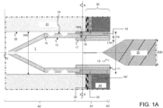
- Figures 1A to 1C show a first embodiment of a composite sealing anchor 1, which is suitable for sealing a penetration 35, such as a borehole, by a composite sealing system 30.
- the Figure 1A a sectional view along the longitudinal axis of the composite waterproofing anchor before screwing in a screw 20 and Figure 1C the same sectional view after screwing in screw 20.
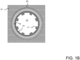
- Figure 1B shows a cross-sectional view through the view from Figure 1A along the section line AA.
- the composite waterproofing system 30 shown in this embodiment comprises a 0.5 mm thick waterproofing membrane 32, which is applied to a building structure in the form of a wall 31.
- the waterproofing membrane 32 supports tiles 34 with a thickness of 10 mm by means of a 3 mm thick layer of tile adhesive 33.
- the penetration 34 which in the embodiment shown has a inner diameter 34D of 10 mm, completely penetrates the waterproofing membrane 32, the tile adhesive 33 and the tiles 34 and penetrates into the wall 31.
- the composite sealing anchor 1 is essentially formed by a hollow cylindrical base body 10 made of polyamide.
- the base body 10 has an opening 13 for the screw 20.
- a section A3 adjoins the first end 11, in which the base body 10 has a radially outwardly directed flange.
- This section A3 extends 1 mm in the axial direction in the embodiment shown.
- This flange-forming section A3 is followed by a (first) section A1, in which the base body 10 has an elastic sealant in the form of an annular elastomer body 19 made of rubber on its radially outer surface 14.
- This annular elastomer body 19 extends 12 mm in the axial direction of the base body and thus has a greater longitudinal extent than the thickness of the composite seal 30.
- the annular elastomer body 19 is inserted 90% in the axial direction into a recess 16, which is formed on the radially outer surface 14 of the base body 10 and extends completely around the base body 10 in the circumferential direction.
- a depth 16H of the recess relative to the adjacent surface 14 of the base body 10 is approximately 1 mm. In this way, the recess 16 fixes the position of the elastomer body 19 relative to the base body 10.
- the end of the recess 16 facing the first end 11 of the base body 10 is clearly delimited by the flange.
- Adjoining the (first) section A1 defined by the annular elastomer body 19 in the axial direction of the base body 10 is a (second) section A2 which is free of the elastomer body 19 and at whose first end 11 in the axial direction of the opposite second end 12 the base body 10 is closed and has a tip.
- the tip facilitates insertion of the base body 10 into the penetration 35.
- the outer surface of the base body 10 is penetrated by a pair of axially oriented slots; these are in the Figures 1A and 1C in the area of the tip of the base body 10.
- the base body 10 has, in this section A2, on its radially outer surface, grooves oriented in the circumferential direction, which alternate in the axial direction with projections oriented in the circumferential direction.
- the base body 10 has, in the (first) section A1 defined by the annular elastomer body 19, projections 17 on its radially inner lateral surface 15, which projections extend in the radial direction relative to the adjacent lateral surface 15 by a height 17H of 1 mm and in the axial direction over the entire length of the annular elastomer body 19.
- the projections 17 promote the radial displacement of the annular elastomer body 19 outward from the base body 10 when the screw 20 is screwed into the composite sealing dowel 1, thus creating a press seal for the penetration 35 and in particular for the composite sealing 30.
- the annular elastomer body 19 penetrates into gaps and cracks in the penetration 35, which in Figure 1C symbolically illustrated by the area marked with the reference numeral 19*. Since the annular elastomer body 19 is arranged not only in the area of the sealing sheet 32 of the composite seal 30, but in the axial direction of the penetration 35 on both sides of the sealing sheet 32, the Composite sealing anchor 1 across layers.
- an outer diameter 1D of the composite sealing anchor 1 must be adapted to an inner diameter 35D of the penetration 35, and an outer diameter 20D of the screw 20 must be adapted to an inner diameter of the composite sealing anchor 1.
- an annular elastomer body 19 provided on the radially outer surface 14 of the base body 10 an annular elastomer body can also be provided on the radially inner surface of the base body 10, which provides the seal against the screw. However, this is not specifically shown in the figures.
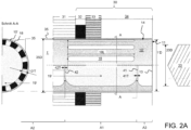
- FIG. 2A shows on the right a sectional view along the longitudinal axis of the composite waterproofing anchor 1' before screwing in a screw 20 and on the left a cross-sectional view along the section line AA through the right figure.
- Figure 2B shows the same views after screwing in screw 20.
- the sealing layer 32 of the composite waterproofing system 30 is not formed by a waterproofing membrane but by a 2 mm thick layer of a formerly liquid waterproofing material applied to a drywall 31.
- the composite sealing dowel 1' according to the second embodiment also has a hollow cylindrical base body 10' made of polyamide and an opening 13 in the axial direction at a first end 11 for receiving a screw 20.
- the base body 10' is not shown over its entire length; in particular, an end opposite the first end 11 is not shown.
- the base body 10' can have a shape that corresponds to the shape of the base body 10 according to the first embodiment in section A2 (which is free of sealant).
- the base body 10' can be closed at its second end, which is opposite the first end 11 in the axial direction.
- the base body 10' has a pasty sealant 19' made of MS polymer inside it. On its radially outer surface, the base body 10' is free of the pasty sealant 19'. The presence of this sealant 19' also defines a (first) section A1 of the base body 10' in the axial direction in this embodiment.
- An outer wall of the base body 10' has twelve elongated holes 18 in this section A1, which are evenly distributed from one another in the circumferential direction of the base body 10'.
- the longitudinal axes of the elongated holes 18 are oriented in the axial direction of the base body 10'.
- the length 18L of the elongated holes 18 is 13 mm each in the embodiment shown, thus exceeding the thickness of conventional composite sealing systems 30.
- the (first) section A1 in which the pasty sealant 19' is arranged, is delimited by first and second partition walls 41, 42.
- the first partition wall 41 closes off the pasty sealant 19' from the opening 13 of the base body 10'
- the second partition wall 42 closes off the pasty sealant 19' from a (second) section A2 of the base body 10', which is free of sealant.
- the second partition wall 42 was Filling of pasty sealant 19' and the first partition wall 41 after filling of pasty sealant 19' is welded to an inner wall of the base body 10'.
- the partition walls 41 and 42 have wall thicknesses 41T and 42T, which correspond to only 15% of an average wall thickness 10'T of the base body 10'.
- An average wall thickness 10'T (corresponding here to the average thickness of the outer wall) of the base body 10' is understood to be the radial distance between a smallest circle defined by a radially outer surface 14 of the base body 10' and a largest circle defined by a radially inner surface of the base body 10', with the centers of both circles coinciding.
- the partition walls 41 and 42 can be easily penetrated by the screw 20.
- section A3 which is free of sealant and adjacent to the first end 11 of the base body 10' with the opening 13, has a significantly greater longitudinal extension of approximately 4 mm and no flange in the second embodiment. The greater length of this section A3 prevents pasty sealant 19' from being forced out of the penetration 35.
- the screw 20 When inserting the screw 20 into the opening 13 of the base body 10', the screw first presses an outer wall of the base body 10' in section A3 outwards, thus ensuring a certain pressure seal to an inner wall of the penetration 35. Subsequently, the screw 20 destroys the first partition 41 and presses the pasty sealant 19' through the elongated holes 18 to the outside of the base body 10', since the pasty sealant 19' is prevented from escaping in the axial direction by the second partition 42. A resulting filling zone for the pasty sealant 19' is shown in Figure 2B shown schematically.
- the filling zone extends not only in the area of the sealing layer 32 of the composite sealing system 30, but also in the axial direction of the penetration 35 to both sides of the sealing layer 32.
- the composite sealing anchor 1 also penetrates across the layers here.
- the screw 20 also destroys the second partition wall 42 and penetrates into the sealant-free section A2 of the base body 10'.
- the latter section A2 serves in particular for the mechanical fastening of the composite sealing anchor 1' in the penetration 35.
- an outer diameter 20D of the screw 20 is to be adapted to an inner diameter of the base body 10' of the composite sealing anchor 1' and an outer diameter 1'D of the composite sealing anchor 1' is to be adapted to an inner diameter 35D of the penetration 35 and thus to be selected appropriately.
- elongated holes were provided in the second embodiment described above to allow the pasty sealant to escape radially from the base body of the composite sealing anchor, the skilled person will recognize that the invention is not limited to the use of elongated holes. Rather, it is possible to provide weakened sections instead of the elongated holes, in which the thickness of the outer wall is reduced by at least 50% compared to the average thickness of the outer wall. As a result, these weakened sections tear open when the screw is screwed in due to the pressure exerted on the pasty sealant, releasing the sealant radially outwards from the base body.
- Figure 3A shows a sectional view along the longitudinal axis of the composite waterproofing anchor 1" before screwing in a screw 20 and Figure 3B The same view appears after screwing in screw 20.
- the composite waterproofing system 30 corresponds to the composite waterproofing system of the first embodiment and has a waterproofing membrane 32 applied to a wall 31, which supports tiles 34 by means of tile adhesive 33.
- the hollow cylindrical base body 10" of the composite sealing anchor 1" is formed on its radially inner and outer surfaces from elastomer layers 101, 103 made of rubber.
- the composite sealing anchor 1" has elastomer both along its entire axial extent and in the circumferential direction on its outer surfaces.
- a core made of a polyamide layer 102 with a wall thickness of 0.5 mm measured in the radial direction is provided between the elastomer layers 101, 103.
- This core provides the composite sealing anchor 1" with axial stability and prevents a screw from completely destroying the elastomer layers 101, 103.
- the thickness of the elastomer layers 101, 103 on the outer surfaces of the composite sealing anchor 1" is 1.5 mm each, measured from the polyamide layer 102 in the radial direction, both to the penetration 35 and to the screw 20.
- the elastomer When screwing in the screw 20, the elastomer is bonded across all layers of the composite sealing system 30 to the inner wall of the penetration 35 as well as the outer wall of the screw 20 and thus completely seals the penetration 35 against the ingress of water.
- the composite sealing anchor 1" unlike in the first embodiment does not have a flange surrounding its opening 13 for the screw 20. However, such a flange can be provided optionally. Furthermore, the composite sealing anchor 1" unlike in Figure 1 As shown, it does not have a point, but is hollow-cylindrical in shape. However, a point may be provided to facilitate insertion of the 1" composite waterproofing anchor into the penetration 35.
- the composite sealing dowel of the first or third embodiment additionally has pasty sealing material in its interior and corresponding openings/weakened portions in the outer surface, which allow the pasty sealing material to escape radially when a screw is screwed in.
- Partition walls can also be provided to delimit the pasty sealing material.
- the composite sealing dowel of the second embodiment can have, on its radially outer and/or radially inner outer surface adjacent to the opening for the screw, an elastic sealant, in particular an annular one, which creates a press seal with the inner wall of the penetration or with the screw when a screw is screwed in, and thus prevents pasty sealant forced out of the composite sealing dowel from escaping from the penetration.
- an elastic sealant in particular an annular one
- this document discloses a composite waterproofing anchor for sealing a penetration through a composite waterproofing system, with a hollow cylindrical base body.
- the base body has an axial Direction at a first end an opening for receiving a screw.
- the base body has at least in one section an elastic or plastic sealant, wherein the sealant 19, 19' is formed from a material which differs from the material from which the base body is formed and is pressed radially outwardly of the base body when the screw is screwed into the composite sealing dowel.
- the entire base body is formed from elastic sealant.
- the composite waterproofing anchor and the screw, in their interaction, ensure that the tightness required for a particular stress class of the composite waterproofing system is also ensured in the area of the penetration.
Landscapes
- Engineering & Computer Science (AREA)
- General Engineering & Computer Science (AREA)
- Mechanical Engineering (AREA)
- Gasket Seals (AREA)
- Building Environments (AREA)
- Dowels (AREA)
Claims (17)
- Cheville d'étanchéité composite (1) comportant un corps de base (10) cylindrique creux,dans laquelle le corps de base (10) présente dans la direction axiale, à une première extrémité (11), une ouverture (13) destinée à recevoir une vis (20),dans laquelle le corps de base (10) présente dans la direction axiale une première section (A1) et une seconde section (A2), dans laquelle la première section (A1) est disposée entre la seconde section (A2) et la première extrémité (11) du corps de base (10),dans laquelle le corps de base (10) présente sur sa surface d'enveloppe (14) située radialement à l'extérieur et, éventuellement, sur sa surface d'enveloppe située radialement à l'intérieur dans la première section (A1), un matériau d'étanchéité (19) et est exempt du matériau d'étanchéité (19) sur sa surface d'enveloppe (14) située radialement à l'extérieur dans la seconde section (A2),dans laquelle le matériau d'étanchéité (19) est formé d'un matériau qui est différent du matériau duquel le corps de base (10) est formé, etdans laquelle le matériau d'étanchéité (19) entoure complètement le corps de base (10) dans la première section (A1) sur sa surface d'enveloppe (14) située radialement à l'extérieur dans la direction circonférentielle du corps de base (10), et forme ainsi un anneau, etdans laquelle le matériau d'étanchéité (19) est formé d'un matériau élastique et est conçu pour fournir une étanchéité des deux côtés d'une étanchéité composite lors du vissage d'une vis (20) dans la cheville d'étanchéité composite (1) ;caractérisée en ce quele corps de base (10) présente dans la première section (A1), sur sa surface d'enveloppe (15) située radialement à l'intérieur, une saillie (17) s'étendant dans les directions radiale et axiale.
- Cheville d'étanchéité composite (1) selon la revendication 1,dans laquelle la première section (A1) du corps de base (10), dans laquelle le corps de base (10) présente un matériau d'étanchéité (19), s'étend dans la direction axiale du corps de base (10) sur entre 10 mm et 15 mm ; et/oudans laquelle la première section du corps de base (10), dans laquelle le corps de base (10) présente un matériau d'étanchéité (19), s'étend dans la direction axiale sur entre 20 % et 70 % de la longueur totale du corps de base (10) ou sur entre 30 % et 60 % de la longueur totale du corps de base (10) ou sur entre 40 % et 50 % de la longueur totale du corps de base (10).
- Cheville d'étanchéité composite (1) selon la revendication 1 ou 2,dans laquelle le matériau formant le corps de base (10) présente dans la première section (A1), sur la surface d'enveloppe (14) située radialement à l'extérieur du corps de base (10), un renfoncement (16) s'étendant dans les directions axiale et radiale, dans lequel renfoncement le matériau d'étanchéité (19) est inséré entièrement ou partiellement ;dans laquelle le renfoncement (16) s'étend dans la direction axiale sur toute la première section (A1) du corps de base (10) ; oudans laquelle le renfoncement (16) s'étend dans la direction axiale sur entre 20 % et 90 % de la première section (A1) du corps de base ; oudans laquelle le renfoncement (16) s'étend dans la direction axiale sur entre 40 % et 85 % de la première section (A1) du corps de base (10) ; oudans laquelle le renfoncement (16) s'étend dans la direction axiale sur entre 60 % et 80 % de la première section (A1) du corps de base (10).
- Cheville d'étanchéité composite (1) selon la revendication 3, dans laquelle le renfoncement (16) s'étend entièrement autour du corps de base (10) dans la direction circonférentielle.
- Cheville d'étanchéité composite (1) selon l'une des revendications 3 ou 4,dans laquelle une profondeur (16H) du renfoncement (16) dans la première section (A1) dans la direction radiale du corps de base (10) est comprise entre 0,25 mm et 2,5 mm ; oudans laquelle une profondeur (16H) du renfoncement (16) dans la première section (A1) dans la direction radiale du corps de base (10) est comprise entre 0,5 mm et 2,25 mm ; oudans laquelle une profondeur (16H) du renfoncement (16) dans la première section (A1) dans la direction radiale du corps de base (10) est comprise entre 1,0 mm et 2,0 mm.
- Cheville d'étanchéité composite (1) selon l'une des revendications 1 à 5,dans laquelle la saillie (17) s'étend dans la direction axiale sur toute la première section (A1) ; oudans laquelle la saillie (17) s'étend dans la direction axiale du corps de base (10) sur entre 25 % et 95 % de la première section (A1) ; oudans laquelle la saillie (17) s'étend dans la direction axiale du corps de base (10) sur entre 45 % et 90 % de la première section (A1) ; oudans laquelle la saillie (17) s'étend dans la direction axiale du corps de base (10) sur entre 65 % et 85 % de la première section (A1).
- Cheville d'étanchéité composite (1) selon l'une des revendications 1 à 6,dans laquelle la saillie (17) s'étend dans la direction circonférentielle entièrement à l'intérieur du corps de base (10) ; oudans laquelle plusieurs saillies (17) séparées les unes des autres sont prévues de manière à être réparties dans la direction circonférentielle.
- Cheville d'étanchéité composite (1) selon l'une des revendications 1 à 7,dans laquelle une hauteur (17H) de la saillie (17) dans la direction radiale du corps de base (10) est comprise entre 0,25 mm et 2,5 mm ; oudans laquelle une hauteur (17H) de la saillie (17) dans la direction radiale du corps de base (10) est comprise entre 0,5 mm et 2,25 mm ; oudans laquelle une hauteur (17H) de la saillie (17) dans la direction radiale du corps de base (10) est comprise entre 1,0 mm et 2,0 mm.
- Cheville d'étanchéité composite (1) selon l'une des revendications 1 à 8, dans laquelle le matériau d'étanchéité (19) est un corps élastomère qui entoure complètement le corps de base (10) dans la direction circonférentielle du corps de base (10), et forme ainsi un anneau.
- Cheville d'étanchéité composite (1) selon l'une des revendications 1 à 9, dans laquelle le corps de base (10) est formé à partir de matière plastique, en particulier de polyamide, ou de métal.
- Cheville d'étanchéité composite (1) selon l'une des revendications 1 à 10,dans laquelle le corps de base (10) présente dans une section au moins une paire de fentes s'étendant dans la direction axiale, lesquelles fentes traversent une surface d'enveloppe du corps de base (10) ; et/oudans laquelle le corps de base (10) présente dans une section, sur sa surface d'enveloppe située radialement à l'extérieur, des rainures orientées dans la direction circonférentielle qui alternent dans la direction axiale avec des saillies orientées dans la direction circonférentielle.
- Procédé permettant d'assurer l'étanchéité d'une percée (35) au moyen d'un système d'étanchéité composite (30), présentant :la fourniture d'une cheville d'étanchéité composite (1) selon l'une des revendications 1 à 11, dans lequel un diamètre extérieur (1D) de la cheville d'étanchéité composite (1) est adapté à un diamètre intérieur de la percée (35D) ;l'insertion de la cheville d'étanchéité composite (1) dans la percée (35) ; etla fourniture d'une vis (20), dans lequel un diamètre extérieur (20D) de la vis est adapté à un diamètre intérieur (10D) du corps de base (10) de la cheville d'étanchéité composite (1) ; etle vissage de la vis (20) dans le corps de base (10) de la cheville d'étanchéité composite (1).
- Utilisation d'une cheville d'étanchéité composite (1) selon l'une des revendications 1 à 11 pour assurer l'étanchéité d'une percée (35) au moyen d'un système d'étanchéité composite (30).
- Système permettant d'assurer l'étanchéité d'une percée (35) au moyen d'un système d'étanchéité composite (30), présentant :une cheville d'étanchéité composite (1) selon l'une des revendications 1 à 11 insérée dans la percée (35) ; etune vis (20) vissée dans la cheville d'étanchéité composite (1),dans lequel la cheville d'étanchéité composite (1) et la vis (20) sont conçues conjointement pour assurer, également dans la zone de la percée (35), une étanchéité requise pour une classe de sollicitation respective du système d'étanchéité composite (30).
- Procédé permettant d'assurer l'étanchéité d'une percée (35) au moyen d'un système d'étanchéité composite (30), présentant :la fourniture d'une cheville d'étanchéité composite (1") comportant un corps de base (10") cylindrique creux,dans lequel le corps de base (10") présente dans la direction axiale, à une première extrémité (11), une ouverture (13) destinée à recevoir une vis (20) ;dans lequel le corps de base (10") présente sur ses surfaces extérieures radialement intérieure et radialement extérieure respectivement des couches d'élastomère (101, 103) qui sont conçues de manière continue respectivement dans la direction axiale et dans la direction circonférentielle de la cheville d'étanchéité composite ; etdans lequel le corps de base (10") présente, radialement à l'intérieur par rapport à la couche d'élastomère (101, 103) située à l'extérieur, une couche de polyamide ou de métal (102) ;dans lequel un diamètre extérieur (1D) de la cheville d'étanchéité composite (1") est adapté à un diamètre intérieur de la percée (35D) ;l'insertion de la cheville d'étanchéité composite (1") dans la percée (35) ; la fourniture d'une vis (20), dans lequel un diamètre extérieur (20D) de la vis est adapté à un diamètre intérieur (10D) du corps de base (10") de la cheville d'étanchéité composite (1") ; etle vissage de la vis (20) dans le corps de base (10") de la cheville d'étanchéité composite (1").
- Procédé selon la revendication 15, dans lequel, pour la cheville d'étanchéité composite (1"), l'épaisseur de chaque couche d'élastomère (101, 103) dans la direction radiale est comprise entre 1 mm et 3 mm ou entre 1,5 mm et 2 mm ; et/ou
l'épaisseur de la couche de polyamide ou de métal (102) dans la direction radiale est comprise entre 0,25 mm et 1,5 mm ou entre 0,4 mm et 0,8 mm. - Utilisation d'une cheville d'étanchéité composite (1") comportant un corps de base (10") cylindrique creux,dans laquelle le corps de base (10") présente dans la direction axiale, à une première extrémité (11), une ouverture (13) destinée à recevoir une vis (20) ;dans laquelle le corps de base (10") présente sur ses surfaces extérieures radialement intérieure et radialement extérieure respectivement des couches d'élastomère (101, 103) qui sont conçues de manière continue respectivement dans la direction axiale et dans la direction circonférentielle de la cheville d'étanchéité composite ; etdans laquelle le corps de base (10") présente, radialement à l'intérieur par rapport à la couche d'élastomère (101, 103) située à l'extérieur, une couche de polyamide ou de métal (102) ;pour assurer l'étanchéité d'une percée (35) au moyen d'un système d'étanchéité composite (30).
Applications Claiming Priority (2)
| Application Number | Priority Date | Filing Date | Title |
|---|---|---|---|
| DE202018003632.3U DE202018003632U1 (de) | 2018-08-03 | 2018-08-03 | Schraubdübel mit Dichtwirkung |
| EP19185074.2A EP3604831B1 (fr) | 2018-08-03 | 2019-07-08 | Cheville d'étanchéité composite |
Related Parent Applications (2)
| Application Number | Title | Priority Date | Filing Date |
|---|---|---|---|
| EP19185074.2A Division-Into EP3604831B1 (fr) | 2018-08-03 | 2019-07-08 | Cheville d'étanchéité composite |
| EP19185074.2A Division EP3604831B1 (fr) | 2018-08-03 | 2019-07-08 | Cheville d'étanchéité composite |
Publications (3)
| Publication Number | Publication Date |
|---|---|
| EP3904704A1 EP3904704A1 (fr) | 2021-11-03 |
| EP3904704B1 true EP3904704B1 (fr) | 2025-03-12 |
| EP3904704C0 EP3904704C0 (fr) | 2025-03-12 |
Family
ID=67220663
Family Applications (2)
| Application Number | Title | Priority Date | Filing Date |
|---|---|---|---|
| EP21181844.8A Active EP3904704B1 (fr) | 2018-08-03 | 2019-07-08 | Cheville composite d'étanchéité |
| EP19185074.2A Active EP3604831B1 (fr) | 2018-08-03 | 2019-07-08 | Cheville d'étanchéité composite |
Family Applications After (1)
| Application Number | Title | Priority Date | Filing Date |
|---|---|---|---|
| EP19185074.2A Active EP3604831B1 (fr) | 2018-08-03 | 2019-07-08 | Cheville d'étanchéité composite |
Country Status (5)
| Country | Link |
|---|---|
| EP (2) | EP3904704B1 (fr) |
| DE (1) | DE202018003632U1 (fr) |
| HU (1) | HUE056288T2 (fr) |
| MA (1) | MA49531A (fr) |
| PL (2) | PL3904704T3 (fr) |
Families Citing this family (4)
| Publication number | Priority date | Publication date | Assignee | Title |
|---|---|---|---|---|
| DK3805578T3 (da) * | 2019-10-11 | 2022-04-04 | Edm System Gmbh | Tætningsmanchet |
| DE102022122613A1 (de) | 2022-09-06 | 2024-03-07 | Adolf Würth GmbH & Co. KG | Dübel mit umfänglich bündig aneinander anliegenden, getrennten Spreizstegen und darin enthaltenem Klebstoff |
| WO2025252676A1 (fr) * | 2024-06-03 | 2025-12-11 | Tirmpas Vasileios | Élément de scellement expansible activé par l'humidité |
| EP4660468A1 (fr) * | 2024-06-03 | 2025-12-10 | Tirmpas, Vasileios | Élément d'étanchéité extensible activé par l'humidité |
Family Cites Families (1)
| Publication number | Priority date | Publication date | Assignee | Title |
|---|---|---|---|---|
| DE19845696A1 (de) * | 1998-10-05 | 2000-04-06 | Grohe Kg Hans | Dübel mit Abdichtung |
-
2018
- 2018-08-03 DE DE202018003632.3U patent/DE202018003632U1/de active Active
-
2019
- 2019-07-08 PL PL21181844.8T patent/PL3904704T3/pl unknown
- 2019-07-08 HU HUE19185074A patent/HUE056288T2/hu unknown
- 2019-07-08 PL PL19185074T patent/PL3604831T3/pl unknown
- 2019-07-08 MA MA049531A patent/MA49531A/fr unknown
- 2019-07-08 EP EP21181844.8A patent/EP3904704B1/fr active Active
- 2019-07-08 EP EP19185074.2A patent/EP3604831B1/fr active Active
Also Published As
| Publication number | Publication date |
|---|---|
| EP3604831B1 (fr) | 2021-08-11 |
| PL3904704T3 (pl) | 2025-09-22 |
| PL3604831T3 (pl) | 2022-01-10 |
| EP3904704A1 (fr) | 2021-11-03 |
| DE202018003632U1 (de) | 2019-08-07 |
| MA49531A (fr) | 2021-04-14 |
| EP3904704C0 (fr) | 2025-03-12 |
| EP3604831A1 (fr) | 2020-02-05 |
| HUE056288T2 (hu) | 2022-02-28 |
Similar Documents
| Publication | Publication Date | Title |
|---|---|---|
| EP3604831B1 (fr) | Cheville d'étanchéité composite | |
| EP3256661A1 (fr) | Élément d'étanchéité de géométrie prédéterminée et dispositif d'étanchéité pourvu d'un tel élément d'étanchéité | |
| DE2910090A1 (de) | Dichtungsstreifen zum abdichten von stossfugen und kreuzungsstellen zwischen bauelementen | |
| EP3621502B1 (fr) | Cordon de joint | |
| EP3587839B1 (fr) | Goujon à deux composants pourvu de brides expansibles dentées rendant impossible le glissement | |
| EP1362961A1 (fr) | Elément de construction pour la protection coupe-feu d' un dispositif d' écoulement et dispositif d'écoulement comprenant un tel élement | |
| DE2659138A1 (de) | Duebel zum einbetonieren in einem bohrloch | |
| EP3667105A1 (fr) | Cheville à expansion en matière plastique, procédé de fixation d'une vis et d'une cheville à expansion en matière plastique et dispositif doté d'une cheville à expansion en matière plastique | |
| EP0246219B1 (fr) | Passage pour tuyau | |
| DE102010034200A1 (de) | Abdichtung zur Einarbeitung für Flächenabdichtungen mit Fliesen im Verbund(II) | |
| AT387835B (de) | Rohrdurchfuehrung | |
| DE102013202002A1 (de) | Dichtungsvorrichtung mit Dichtungskörper und Dichtungsmasse | |
| DE19845696A1 (de) | Dübel mit Abdichtung | |
| EP4517114A1 (fr) | Douille d'ancrage, ensemble et procédé de fixation | |
| EP1505218B1 (fr) | Système composite d'isolation thermique | |
| DE4336379A1 (de) | Abdichtungsprofil für Fugen zwischen Betonplatten und Verfahren zur Fugenabdichtung einer Fuge zwischen zwei Betonplatten mit einem derartigen Abdichtungsprofil | |
| DE10028202C2 (de) | Eckabdichtung an Bauwerken | |
| EP3735548B1 (fr) | Manchette étanche pour joints composites | |
| DE29719406U1 (de) | Injektionsschlauch für Arbeitsfugen an Betonbauwerken | |
| DE202020106135U1 (de) | Dübel und Befestigungssystem | |
| EP4336056B1 (fr) | Cheville avec nervures d'écartement séparées adjacentes circonférentiellement affleurantes et adhésif contenu dans celle-ci | |
| DE10043848B4 (de) | Montagehülse für einen Wandanker | |
| DE20200448U1 (de) | Bandartige Vorrichtung zum Schließen einer zwischen zwei Bauteilen angeordneten Fuge | |
| DE102024133074A1 (de) | Dichtrohr mit Quellelement | |
| AT514015A2 (de) | Abdichtelement, Verfahren und Befestigungsanordnung mit dem Abdichtelement |
Legal Events
| Date | Code | Title | Description |
|---|---|---|---|
| PUAI | Public reference made under article 153(3) epc to a published international application that has entered the european phase |
Free format text: ORIGINAL CODE: 0009012 |
|
| STAA | Information on the status of an ep patent application or granted ep patent |
Free format text: STATUS: THE APPLICATION HAS BEEN PUBLISHED |
|
| AC | Divisional application: reference to earlier application |
Ref document number: 3604831 Country of ref document: EP Kind code of ref document: P |
|
| AK | Designated contracting states |
Kind code of ref document: A1 Designated state(s): AL AT BE BG CH CY CZ DE DK EE ES FI FR GB GR HR HU IE IS IT LI LT LU LV MC MK MT NL NO PL PT RO RS SE SI SK SM TR |
|
| B565 | Issuance of search results under rule 164(2) epc |
Effective date: 20211001 |
|
| STAA | Information on the status of an ep patent application or granted ep patent |
Free format text: STATUS: REQUEST FOR EXAMINATION WAS MADE |
|
| 17P | Request for examination filed |
Effective date: 20211130 |
|
| RBV | Designated contracting states (corrected) |
Designated state(s): AL AT BE BG CH CY CZ DE DK EE ES FI FR GB GR HR HU IE IS IT LI LT LU LV MC MK MT NL NO PL PT RO RS SE SI SK SM TR |
|
| P01 | Opt-out of the competence of the unified patent court (upc) registered |
Effective date: 20230519 |
|
| STAA | Information on the status of an ep patent application or granted ep patent |
Free format text: STATUS: EXAMINATION IS IN PROGRESS |
|
| 17Q | First examination report despatched |
Effective date: 20240131 |
|
| GRAP | Despatch of communication of intention to grant a patent |
Free format text: ORIGINAL CODE: EPIDOSNIGR1 |
|
| STAA | Information on the status of an ep patent application or granted ep patent |
Free format text: STATUS: GRANT OF PATENT IS INTENDED |
|
| INTG | Intention to grant announced |
Effective date: 20241008 |
|
| GRAS | Grant fee paid |
Free format text: ORIGINAL CODE: EPIDOSNIGR3 |
|
| GRAA | (expected) grant |
Free format text: ORIGINAL CODE: 0009210 |
|
| STAA | Information on the status of an ep patent application or granted ep patent |
Free format text: STATUS: THE PATENT HAS BEEN GRANTED |
|
| AC | Divisional application: reference to earlier application |
Ref document number: 3604831 Country of ref document: EP Kind code of ref document: P |
|
| AK | Designated contracting states |
Kind code of ref document: B1 Designated state(s): AL AT BE BG CH CY CZ DE DK EE ES FI FR GB GR HR HU IE IS IT LI LT LU LV MC MK MT NL NO PL PT RO RS SE SI SK SM TR |
|
| REG | Reference to a national code |
Ref country code: GB Ref legal event code: FG4D Free format text: NOT ENGLISH |
|
| REG | Reference to a national code |
Ref country code: CH Ref legal event code: EP |
|
| REG | Reference to a national code |
Ref country code: DE Ref legal event code: R096 Ref document number: 502019013064 Country of ref document: DE |
|
| REG | Reference to a national code |
Ref country code: IE Ref legal event code: FG4D Free format text: LANGUAGE OF EP DOCUMENT: GERMAN |
|
| U01 | Request for unitary effect filed |
Effective date: 20250313 |
|
| P04 | Withdrawal of opt-out of the competence of the unified patent court (upc) registered |
Free format text: CASE NUMBER: APP_13209/2025 Effective date: 20250317 |
|
| U07 | Unitary effect registered |
Designated state(s): AT BE BG DE DK EE FI FR IT LT LU LV MT NL PT RO SE SI Effective date: 20250320 |
|
| U20 | Renewal fee for the european patent with unitary effect paid |
Year of fee payment: 7 Effective date: 20250513 |
|
| PG25 | Lapsed in a contracting state [announced via postgrant information from national office to epo] |
Ref country code: RS Free format text: LAPSE BECAUSE OF FAILURE TO SUBMIT A TRANSLATION OF THE DESCRIPTION OR TO PAY THE FEE WITHIN THE PRESCRIBED TIME-LIMIT Effective date: 20250612 |
|
| PG25 | Lapsed in a contracting state [announced via postgrant information from national office to epo] |
Ref country code: ES Free format text: LAPSE BECAUSE OF FAILURE TO SUBMIT A TRANSLATION OF THE DESCRIPTION OR TO PAY THE FEE WITHIN THE PRESCRIBED TIME-LIMIT Effective date: 20250312 |
|
| PG25 | Lapsed in a contracting state [announced via postgrant information from national office to epo] |
Ref country code: NO Free format text: LAPSE BECAUSE OF FAILURE TO SUBMIT A TRANSLATION OF THE DESCRIPTION OR TO PAY THE FEE WITHIN THE PRESCRIBED TIME-LIMIT Effective date: 20250612 |
|
| PG25 | Lapsed in a contracting state [announced via postgrant information from national office to epo] |
Ref country code: HR Free format text: LAPSE BECAUSE OF FAILURE TO SUBMIT A TRANSLATION OF THE DESCRIPTION OR TO PAY THE FEE WITHIN THE PRESCRIBED TIME-LIMIT Effective date: 20250312 |
|
| PG25 | Lapsed in a contracting state [announced via postgrant information from national office to epo] |
Ref country code: GR Free format text: LAPSE BECAUSE OF FAILURE TO SUBMIT A TRANSLATION OF THE DESCRIPTION OR TO PAY THE FEE WITHIN THE PRESCRIBED TIME-LIMIT Effective date: 20250613 |
|
| PG25 | Lapsed in a contracting state [announced via postgrant information from national office to epo] |
Ref country code: SM Free format text: LAPSE BECAUSE OF FAILURE TO SUBMIT A TRANSLATION OF THE DESCRIPTION OR TO PAY THE FEE WITHIN THE PRESCRIBED TIME-LIMIT Effective date: 20250312 |
|
| PGFP | Annual fee paid to national office [announced via postgrant information from national office to epo] |
Ref country code: PL Payment date: 20250417 Year of fee payment: 7 |
|
| PGFP | Annual fee paid to national office [announced via postgrant information from national office to epo] |
Ref country code: CH Payment date: 20250801 Year of fee payment: 7 |
|
| PG25 | Lapsed in a contracting state [announced via postgrant information from national office to epo] |
Ref country code: CZ Free format text: LAPSE BECAUSE OF FAILURE TO SUBMIT A TRANSLATION OF THE DESCRIPTION OR TO PAY THE FEE WITHIN THE PRESCRIBED TIME-LIMIT Effective date: 20250312 |
|
| PG25 | Lapsed in a contracting state [announced via postgrant information from national office to epo] |
Ref country code: SK Free format text: LAPSE BECAUSE OF FAILURE TO SUBMIT A TRANSLATION OF THE DESCRIPTION OR TO PAY THE FEE WITHIN THE PRESCRIBED TIME-LIMIT Effective date: 20250312 |
|
| PG25 | Lapsed in a contracting state [announced via postgrant information from national office to epo] |
Ref country code: IS Free format text: LAPSE BECAUSE OF FAILURE TO SUBMIT A TRANSLATION OF THE DESCRIPTION OR TO PAY THE FEE WITHIN THE PRESCRIBED TIME-LIMIT Effective date: 20250712 |
|
| PLBE | No opposition filed within time limit |
Free format text: ORIGINAL CODE: 0009261 |
|
| STAA | Information on the status of an ep patent application or granted ep patent |
Free format text: STATUS: NO OPPOSITION FILED WITHIN TIME LIMIT |
|
| REG | Reference to a national code |
Ref country code: CH Ref legal event code: L10 Free format text: ST27 STATUS EVENT CODE: U-0-0-L10-L00 (AS PROVIDED BY THE NATIONAL OFFICE) Effective date: 20260121 |
|
| 26N | No opposition filed |
Effective date: 20251215 |
|
| GBPC | Gb: european patent ceased through non-payment of renewal fee |
Effective date: 20250708 |
|
| PG25 | Lapsed in a contracting state [announced via postgrant information from national office to epo] |
Ref country code: GB Free format text: LAPSE BECAUSE OF NON-PAYMENT OF DUE FEES Effective date: 20250708 |