EP3905960B1 - Systeme und verfahren zur kontrastverstärkten bildgebung - Google Patents
Systeme und verfahren zur kontrastverstärkten bildgebung Download PDFInfo
- Publication number
- EP3905960B1 EP3905960B1 EP19829620.4A EP19829620A EP3905960B1 EP 3905960 B1 EP3905960 B1 EP 3905960B1 EP 19829620 A EP19829620 A EP 19829620A EP 3905960 B1 EP3905960 B1 EP 3905960B1
- Authority
- EP
- European Patent Office
- Prior art keywords
- microbubbles
- ultrasound
- processor
- identified
- pixels
- Prior art date
- Legal status (The legal status is an assumption and is not a legal conclusion. Google has not performed a legal analysis and makes no representation as to the accuracy of the status listed.)
- Active
Links
Images


Classifications
-
- A—HUMAN NECESSITIES
- A61—MEDICAL OR VETERINARY SCIENCE; HYGIENE
- A61B—DIAGNOSIS; SURGERY; IDENTIFICATION
- A61B8/00—Diagnosis using ultrasonic, sonic or infrasonic waves
- A61B8/48—Diagnostic techniques
- A61B8/481—Diagnostic techniques involving the use of contrast agents, e.g. microbubbles introduced into the bloodstream
-
- A—HUMAN NECESSITIES
- A61—MEDICAL OR VETERINARY SCIENCE; HYGIENE
- A61B—DIAGNOSIS; SURGERY; IDENTIFICATION
- A61B8/00—Diagnosis using ultrasonic, sonic or infrasonic waves
- A61B8/08—Clinical applications
- A61B8/0833—Clinical applications involving detecting or locating foreign bodies or organic structures
- A61B8/085—Clinical applications involving detecting or locating foreign bodies or organic structures for locating body or organic structures, e.g. tumours, calculi, blood vessels, nodules
-
- A—HUMAN NECESSITIES
- A61—MEDICAL OR VETERINARY SCIENCE; HYGIENE
- A61B—DIAGNOSIS; SURGERY; IDENTIFICATION
- A61B8/00—Diagnosis using ultrasonic, sonic or infrasonic waves
- A61B8/08—Clinical applications
- A61B8/0891—Clinical applications for diagnosis of blood vessels
-
- A—HUMAN NECESSITIES
- A61—MEDICAL OR VETERINARY SCIENCE; HYGIENE
- A61B—DIAGNOSIS; SURGERY; IDENTIFICATION
- A61B8/00—Diagnosis using ultrasonic, sonic or infrasonic waves
- A61B8/46—Ultrasonic, sonic or infrasonic diagnostic devices with special arrangements for interfacing with the operator or the patient
- A61B8/467—Ultrasonic, sonic or infrasonic diagnostic devices with special arrangements for interfacing with the operator or the patient characterised by special input means
-
- A—HUMAN NECESSITIES
- A61—MEDICAL OR VETERINARY SCIENCE; HYGIENE
- A61B—DIAGNOSIS; SURGERY; IDENTIFICATION
- A61B8/00—Diagnosis using ultrasonic, sonic or infrasonic waves
- A61B8/52—Devices using data or image processing specially adapted for diagnosis using ultrasonic, sonic or infrasonic waves
- A61B8/5207—Devices using data or image processing specially adapted for diagnosis using ultrasonic, sonic or infrasonic waves involving processing of raw data to produce diagnostic data, e.g. for generating an image
-
- A—HUMAN NECESSITIES
- A61—MEDICAL OR VETERINARY SCIENCE; HYGIENE
- A61B—DIAGNOSIS; SURGERY; IDENTIFICATION
- A61B8/00—Diagnosis using ultrasonic, sonic or infrasonic waves
- A61B8/52—Devices using data or image processing specially adapted for diagnosis using ultrasonic, sonic or infrasonic waves
- A61B8/5215—Devices using data or image processing specially adapted for diagnosis using ultrasonic, sonic or infrasonic waves involving processing of medical diagnostic data
- A61B8/5238—Devices using data or image processing specially adapted for diagnosis using ultrasonic, sonic or infrasonic waves involving processing of medical diagnostic data for combining image data of patient, e.g. merging several images from different acquisition modes into one image
- A61B8/5246—Devices using data or image processing specially adapted for diagnosis using ultrasonic, sonic or infrasonic waves involving processing of medical diagnostic data for combining image data of patient, e.g. merging several images from different acquisition modes into one image combining images from the same or different imaging techniques, e.g. color Doppler and B-mode
-
- A—HUMAN NECESSITIES
- A61—MEDICAL OR VETERINARY SCIENCE; HYGIENE
- A61B—DIAGNOSIS; SURGERY; IDENTIFICATION
- A61B8/00—Diagnosis using ultrasonic, sonic or infrasonic waves
- A61B8/52—Devices using data or image processing specially adapted for diagnosis using ultrasonic, sonic or infrasonic waves
- A61B8/5269—Devices using data or image processing specially adapted for diagnosis using ultrasonic, sonic or infrasonic waves involving detection or reduction of artifacts
-
- A—HUMAN NECESSITIES
- A61—MEDICAL OR VETERINARY SCIENCE; HYGIENE
- A61B—DIAGNOSIS; SURGERY; IDENTIFICATION
- A61B8/00—Diagnosis using ultrasonic, sonic or infrasonic waves
- A61B8/52—Devices using data or image processing specially adapted for diagnosis using ultrasonic, sonic or infrasonic waves
- A61B8/5269—Devices using data or image processing specially adapted for diagnosis using ultrasonic, sonic or infrasonic waves involving detection or reduction of artifacts
- A61B8/5276—Devices using data or image processing specially adapted for diagnosis using ultrasonic, sonic or infrasonic waves involving detection or reduction of artifacts due to motion
-
- G—PHYSICS
- G06—COMPUTING OR CALCULATING; COUNTING
- G06T—IMAGE DATA PROCESSING OR GENERATION, IN GENERAL
- G06T5/00—Image enhancement or restoration
- G06T5/50—Image enhancement or restoration using two or more images, e.g. averaging or subtraction
-
- G—PHYSICS
- G06—COMPUTING OR CALCULATING; COUNTING
- G06T—IMAGE DATA PROCESSING OR GENERATION, IN GENERAL
- G06T5/00—Image enhancement or restoration
- G06T5/90—Dynamic range modification of images or parts thereof
- G06T5/92—Dynamic range modification of images or parts thereof based on global image properties
-
- G—PHYSICS
- G06—COMPUTING OR CALCULATING; COUNTING
- G06T—IMAGE DATA PROCESSING OR GENERATION, IN GENERAL
- G06T7/00—Image analysis
- G06T7/20—Analysis of motion
-
- G—PHYSICS
- G06—COMPUTING OR CALCULATING; COUNTING
- G06T—IMAGE DATA PROCESSING OR GENERATION, IN GENERAL
- G06T2200/00—Indexing scheme for image data processing or generation, in general
- G06T2200/24—Indexing scheme for image data processing or generation, in general involving graphical user interfaces [GUIs]
-
- G—PHYSICS
- G06—COMPUTING OR CALCULATING; COUNTING
- G06T—IMAGE DATA PROCESSING OR GENERATION, IN GENERAL
- G06T2207/00—Indexing scheme for image analysis or image enhancement
- G06T2207/10—Image acquisition modality
- G06T2207/10132—Ultrasound image
-
- G—PHYSICS
- G06—COMPUTING OR CALCULATING; COUNTING
- G06T—IMAGE DATA PROCESSING OR GENERATION, IN GENERAL
- G06T2207/00—Indexing scheme for image analysis or image enhancement
- G06T2207/20—Special algorithmic details
- G06T2207/20172—Image enhancement details
- G06T2207/20208—High dynamic range [HDR] image processing
-
- G—PHYSICS
- G06—COMPUTING OR CALCULATING; COUNTING
- G06T—IMAGE DATA PROCESSING OR GENERATION, IN GENERAL
- G06T2207/00—Indexing scheme for image analysis or image enhancement
- G06T2207/30—Subject of image; Context of image processing
- G06T2207/30004—Biomedical image processing
- G06T2207/30101—Blood vessel; Artery; Vein; Vascular
Definitions
- This application relates to contrast enhanced imaging. More specifically, this application relates to contrast enhanced ultrasound for vascular imaging.
- WO 2014/179681 A1 discloses systems and methods for ultrasound imaging capable of achieving spatial resolutions that can resolve objects smaller than 300 ⁇ m.
- WO 2018/042191 A1 discloses an ultrasound imaging method in which ultrasound signals are transmitted and received with a resolution limit in a first direction, wherein a peak-sharpening operation is applied to image data generated from the received ultrasound signals in order to obtain images having a finer resolution in the first direction than the resolution limit.
- a contrast agent is provided to an area or volume to be imaged in order to provide a higher signal strength from the area or volume, or selectively enhance signals from areas or volumes with high contrast concentration.
- contrast-enhanced ultrasound CEUS
- microbubbles may be injected into a subject's bloodstream and ultrasound images may be acquired of the subject's vasculature. Without the microbubbles, little to no signal may be provided by the blood vessels.
- contrast accumulation imaging CAI
- multiple contrast-enhanced images e.g., multiple image frames
- CAI contrast accumulation imaging
- CEUS Temporal accumulation imaging of CEUS has been commercialized and widely used for vascularity visualization.
- CEUS has limited spatial resolution due to the large size of the point spread function (PSF) in contrast mode.
- the PSF is a measure of blurring or spreading of a point source by an imaging system.
- CEUS may also have strong residual clutter artifacts as well as vulnerability to patient induced motion due to the combining of multiple image frames to form the final image.
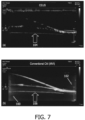
- FIG. 7 shows example (a) CEUS and (b) CAI images of a two-branch flow phantom with circulating microbubbles.
- the CEUS image has "holes" in the visualization of the vasculature because microbubbles are not present at every point in the vasculature during a single image acquisition.
- a more complete image of the vasculature can be seen in the CAI image of FIG 7(b) .
- the CAI image suffers from low spatial resolution.
- CAI has similar spatial resolution to CEUS, however, in practice, its resolution is worse due to tissue motion and clutter artifacts.
- the clutter artifacts act as false positives for microbubbles and/or vasculature.
- the present disclosure describes a contrast accumulation imaging technique that may provide improved imaging performance that strategically selects multiple pixels to represent one or more microbubbles localized within an image.
- the systems and methods described herein may particularly localize each microbubble with its more specific characteristics and may provide better spatial resolution than CAI, adjustable spatial resolution, and/or less residual clutter than CAI which may result in higher contrast-to-tissue ratio (CTR).
- CTR contrast-to-tissue ratio
- the system and methods described herein may provide contrast enhanced images at regular CEUS frame rates (e.g. 15-25 Hz) with shorter data acquisition times (e.g., approximately 20 s) compared to Super-resolution imaging.
- Super-resolution imaging also known as ultrasound localization microscopy (ULM)
- SRI ultrasound localization microscopy
- ULM ultrasound localization microscopy
- It has several advantages: (1) high spatial resolution (up to ⁇ 8 ⁇ m ⁇ 10 ⁇ m, almost close to the size of red blood cells); (2) same penetration depth as regular CEUS; (3) quantification of blood flow in both magnitude and direction (also, optionally, speed of propagation); (4) non-invasive with non-toxic microbubble-based contrast agents; (5) no hardware modifications to existing clinical scanners.
- each super-resolved image is obtained by two steps: (1) localizing the center of each separable microbubble and then (2) accumulating these centers over thousands of acquisitions.
- the position of each microbubble is obtained by taking the local maxima of each microbubble intensity profile. This means that the center of each microbubble can be seen and represented as a single-pixel dot.
- the center of each microbubble can be obtained also with the following methods: (1) directly finding the peak (maximum intensity) of each separable microbubble in image domain; or (2) fitting the microbubble image with a 2D/3D Gaussian function and then finding the peak; or (3) fitting the microbubble image with the PSF of the imaging system and then finding the peak.
- maximum pixel projection technique is used to refer to the accumulation of center positions from multiple acquisitions (e.g., multiple image frames).
- the accumulation of the center positions of microbubbles is the probability density mapping of microbubbles, which is the super-resolved image of the microvasculature.
- SRI typically requires tens or hundreds of thousands of individual contrast imaging frames, corresponding to a combination of very high imaging frame rates (often >500 Hz) and very long acquisition times (e.g., several minutes) compared to conventional contrast ultrasound scans. It is very challenging to achieve acceptable super-resolved images with regular CEUS frame rate (e.g., 15-25 Hz) and short acquisition time (e.g., 20 s). High imaging frame rate in SRI is preferable for (1) good separation of individual microbubbles, (2) sufficient accumulation of microbubbles, and (3) adequate motion compensation. SRI with low frame rate ( ⁇ 25 Hz, as in conventional CEUS) is limited by motion artifacts and requires prolonged acquisition times (>30 min).
- the acquisition time is not sufficient, the super-resolved image may not be properly formed due to partial filling and a large number of "holes". Hemodynamically, large blood vessels (diameter>100 ⁇ m) get perfused more quickly. Hence, the acquisition time required to reconstruct them may be much shorter than for very small vessels ( ⁇ 20 ⁇ m and smaller). Since SRI is a technique developed to mainly image small structures--for example, capillaries with diameter less than 20 ⁇ m--the data acquisition time has to be long enough to reconstruct such microvessels.
- Spatial resolution and temporal resolution of SRI may be related to the local concentration of microbubbles, given that this technique reconstructs microvessels based on the localized sources (e.g., microbubbles) within them (e.g., single-pixel dot is used to represent each microbubble for accumulation). For example, a high concentration of microbubbles and an accumulation of 75,000 images (e.g., acquisition time of 150 s at frame rate of 500 Hz), yielding 1,000,000 events (e.g., microbubbles) may be used to generate one super-resolved image with 10 ⁇ m spatial resolution.
- this technique reconstructs microvessels based on the localized sources (e.g., microbubbles) within them (e.g., single-pixel dot is used to represent each microbubble for accumulation).
- a high concentration of microbubbles and an accumulation of 75,000 images e.g., acquisition time of 150 s at frame rate of 500 Hz
- yielding 1,000,000 events e.g., micro
- the present disclosure is directed to systems and methods for performing imaging techniques with adjustable resolution and acquisition times, which may be tailored to different clinical applications intended for the visualization of different vascular levels of organs or diseases.
- the present disclosure describes a contrast accumulation imaging technique that strategically selects multiple pixels to represent one or more microbubbles localized within an image, as opposed to a large number of pixels associated with a general PSF of CAI or a single pixel representation of SRI.
- the pixels representing microbubbles are selected by applying a filter to the image data such that multiple pixels are representative of the microbubbles within the image data.
- the filter may include an intensity threshold of a value between a maximum pixel intensity and a minimum pixel intensity associated with identified microbubbles.
- the filter may select a certain percentage of pixels whose intensity is greater than the mean signal intensity.
- the filter may include other thresholds or algorithms to select the pixels representative of the microbubbles.
- the pixel intensity values for the filter may be preset or estimated based on existing image data. This filtered technique may allow microbubbles of different intensity values to be localized and accumulated in subsequent imaging frames to achieve a high-resolution image (e.g., an enhanced CAI image).
- the techniques described herein may be referred to as "enhanced CAI.”
- contrast-enhanced images may be generated from the ultrasound signals.
- the ultrasound imaging system may separate the signals to generate contrast images to visualize the contrast agent and tissue images to visualize tissue structures.
- the ultrasound imaging system may include at least one processor configured to identify microbubbles in the ultrasound signals and/or the images. After identification, the at least one processor may localize the microbubbles by representing each identified microbubble by multiple pixels by passing the identified microbubbles through a filter. The number of pixels may depend on a threshold value of a filter.
- Multiple ultrasound signals e.g., signals based on echoes received from multiple transmit/receive events
- multiple image frames processed by the at least one processor may be combined to form a final enhanced contrast accumulation image.
- the at least one processor may perform motion estimation and compensation prior to accumulating the images.
- the at least one processor may pass the ultrasound signals and/or images through one or more clutter rejection filters.
- FIG. 1 shows a block diagram of an ultrasound imaging system 200 constructed in accordance with the principles of the present disclosure.
- An ultrasound imaging system 200 may include a transducer array 214, which may be included in an ultrasound probe 212, for example an external probe or an internal probe such as an intravascular ultrasound (IVUS) catheter probe.
- the transducer array 214 may be in the form of a flexible array configured to be conformally applied to a surface of subject to be imaged (e.g., patient).
- the transducer array 214 is configured to transmit ultrasound signals (e.g., beams, waves) and receive echoes (e.g., received ultrasound signals) responsive to the transmitted ultrasound signals.
- transducer arrays may be used, e.g., linear arrays, curved arrays, or phased arrays.
- the transducer array 214 can include a two-dimensional array (as shown) of transducer elements capable of scanning in both elevation and azimuth dimensions for 2D and/or 3D imaging.
- the axial direction is the direction normal to the face of the array (in the case of a curved array the axial directions fan out)
- the azimuthal direction is defined generally by the longitudinal dimension of the array
- the elevation direction is transverse to the azimuthal direction.
- the transducer array 214 may be coupled to a microbeamformer 216, which may be located in the ultrasound probe 212, and which may control the transmission and reception of signals by the transducer elements in the array 214.
- the microbeamformer 216 may control the transmission and reception of signals by active elements in the array 214 (e.g., an active subset of elements of the array that define the active aperture at any given time).
- the microbeamformer 216 may be coupled, e.g., by a probe cable or wirelessly, to a transmit/receive (T/R) switch 218, which switches between transmission and reception and protects the main beamformer 222 from high energy transmit signals.
- T/R transmit/receive
- the T/R switch 218 and other elements in the system can be included in the ultrasound probe 212 rather than in the ultrasound system base, which may house the image processing electronics.
- An ultrasound system base typically includes software and hardware components including circuitry for signal processing and image data generation as well as executable instructions for providing a user interface.
- the transmission of ultrasonic signals from the transducer array 214 under control of the microbeamformer 216 is directed by the transmit controller 220, which may be coupled to the T/R switch 218 and a main beamformer 222.
- the transmit controller 220 may control the direction in which beams are steered. Beams may be steered straight ahead from (orthogonal to) the transducer array 214, or at different angles for a wider field of view.
- the transmit controller 220 may also be coupled to a user interface 224 and receive input from the user's operation of a user control.
- the user interface 224 may include one or more input devices such as a control panel 252, which may include one or more mechanical controls (e.g., buttons, encoders, etc.), touch sensitive controls (e.g., a trackpad, a touchscreen, or the like), and/or other known input devices.
- a control panel 252 may include one or more mechanical controls (e.g., buttons, encoders, etc.), touch sensitive controls (e.g., a trackpad, a touchscreen, or the like), and/or other known input devices.
- the partially beamformed signals produced by the microbeamformer 216 may be coupled to a main beamformer 222 where partially beamformed signals from individual patches of transducer elements may be combined into a fully beamformed signal.
- microbeamformer 216 is omitted, and the transducer array 214 is under the control of the beamformer 222 and beamformer 222 performs all beamforming of signals.
- the beamformed signals of beamformer 222 are coupled to processing circuitry 250, which may include one or more processors (e.g., a signal processor 226, a B-mode processor 228, a Doppler processor 260, and one or more image generation and processing components 268) configured to produce an ultrasound image from the beamformed signals (i.e., beamformed RF data).
- processors e.g., a signal processor 226, a B-mode processor 228, a Doppler processor 260, and one or more image generation and processing components 268, configured to produce an ultrasound image from the beamformed signals (i.e., beamformed RF data).
- the signal processor 226 may be configured to process the received beamformed RF data in various ways, such as bandpass filtering, decimation, I and Q component separation, and harmonic signal separation.
- the signal processor 226 may also perform additional signal enhancement such as speckle reduction, signal compounding, and electronic noise elimination.
- the processed signals (also referred to as I and Q components or IQ signals) may be coupled to additional downstream signal processing circuits for image generation.
- the IQ signals may be coupled to a plurality of signal paths within the system, each of which may be associated with a specific arrangement of signal processing components suitable for generating different types of image data (e.g., B-mode image data, Doppler image data).
- the system may include a B-mode signal path 258 which couples the signals from the signal processor 226 to a B-mode processor 228 for producing B-mode image data.
- the signal processor 226 may analyze the RF data and/or IQ signals to identify and localize microbubbles in the signals.
- the processed signals may be provided to the B-mode processor 228 and other processing circuitry (e.g., scan converter, 230, image processor 236) for accumulation and generation of an enhanced CAI image.
- the signal processor 226 may accumulate the signals over multiple transmit/receive events to generate a combined signal to be further processed into an enhanced CAI image by the B-mode processor 228 and other processing circuitry.
- the B-mode processor 228 can employ amplitude detection for the imaging of structures in the body. According to principles of the present disclosure, the B-mode processor 228 may generate signals for tissue images and/or contrast images. Because microbubbles may generate much higher intensity echoes than the surrounding tissue, signals from the microbubbles may be extracted from the B-mode signal for forming a separate contrast image. Similarly, the lower intensity tissue signals may be separated from the microbubble signals for generating a tissue image.
- the signals produced by the B-mode processor 228 may be coupled to a scan converter 230 and/or a multiplanar reformatter 232.
- the scan converter 230 may be configured to arrange the echo signals from the spatial relationship in which they were received to a desired image format.
- the scan converter 230 may arrange the echo signal into a two-dimensional (2D) sector-shaped format, or a pyramidal or otherwise shaped three-dimensional (3D) format.
- the scan converter 230 may arrange the echo signals into side-by-side contrast enhanced and tissue images.
- the image processor 236 performs microbubble identification, localization, and accumulation.
- the multiplanar reformatter 232 can convert echoes which are received from points in a common plane in a volumetric region of the body into an ultrasonic image (e.g., a B-mode image) of that plane, for example as described in U.S. Pat. No. 6,443,896 (Detmer ).
- the scan converter 230 and multiplanar reformatter 232 may be implemented as one or more processors in some examples.
- a volume renderer 234 may generate an image (also referred to as a projection, render, or rendering) of the 3D dataset as viewed from a given reference point, e.g., as described in U.S. Pat. No. 6,530,885 (Entrekin et al. ).
- the volume renderer 234 may be implemented as one or more processors in some examples.
- the volume renderer 234 may generate a render, such as a positive render or a negative render, by any known or future known technique such as surface rendering and maximum intensity rendering.
- the system may include a Doppler signal path 262 which couples the output from the signal processor 226 to a Doppler processor 260.
- the Doppler processor 260 may be configured to estimate the Doppler shift and generate Doppler image data.
- the Doppler image data may include color data which is then overlaid with B-mode (i.e. grayscale) image data for display.
- B-mode i.e. grayscale
- the Doppler processor 260 may be configured to filter out unwanted signals (i.e., noise or clutter associated with non-moving tissue), for example using a wall filter.
- the Doppler processor 260 may be further configured to estimate velocity and power in accordance with known techniques.
- the Doppler processor may include a Doppler estimator such as an auto-correlator, in which velocity (Doppler frequency) estimation is based on the argument of the lag-one autocorrelation function and Doppler power estimation is based on the magnitude of the lag-zero autocorrelation function.
- Motion can also be estimated by known phase-domain (for example, parametric frequency estimators such as MUSIC, ESPRIT, etc.) or time-domain (for example, cross-correlation) signal processing techniques.
- Other estimators related to the temporal or spatial distributions of velocity such as estimators of acceleration or temporal and/or spatial velocity derivatives can be used instead of or in addition to velocity estimators.
- the velocity and power estimates may undergo further threshold detection to further reduce noise, as well as segmentation and post-processing such as filling and smoothing.
- the velocity and power estimates may then be mapped to a desired range of display colors in accordance with a color map.
- the color data also referred to as Doppler image data, may then be coupled to the scan converter 230, where the Doppler image data may be converted to the desired image format and overlaid on the B-mode image of the tissue structure to form a color Doppler or a power Doppler image.
- Doppler image data may be overlaid on a B-mode image of the tissue structure.
- Output (e.g., B-mode images, Doppler images) from the scan converter 230, the multiplanar reformatter 232, and/or the volume renderer 334 may be coupled to an image processor 236 for further enhancement, buffering and temporary storage before being displayed on an image display 238.
- image processor 236 for further enhancement, buffering and temporary storage before being displayed on an image display 238.
- the image processor 236 may analyze one or more images to identify and localize one or more microbubbles within an image based on multiple pixels per microbubble.
- identifying microbubbles may include identifying a general microbubble region (e.g. using PSF) and then applying one or more filters to the general microbubble region to identify one or more particular microbubbles.
- pixels with intensities greater than a threshold of the filter are classified as a microbubble.
- the one or more filters may further be used to localize the microbubbles by representing centers of the microbubbles as multiple pixels.
- the filters may be preset (e.g., based on exam type and/or contrast agent type).
- the filters are based on the range of intensities presented in the microbubble region of the image. In other examples, the filters may be set by a user input.
- the filters apply threshold values and/or may apply other selection algorithms for determining which pixels to visualize.
- the threshold value may be an intensity value.
- the threshold value is an intensity threshold which is less than the maximum intensity (e.g., 80%, 90%) and greater than the minimum intensity (e.g., 50%, 60%) of the microbubble so that the microbubble representation is a multi-pixel spot which is greater than one pixel, but the extent of the pixels is less than the entire microbubble (e.g. PSF). As the percentage of the maximum intensity increases, the number of pixels representing each microbubble decreases and the resolution increases.
- a plurality of microbubbles may be localized within the PSF, and each microbubble may have its own intensity or pixel signature in some examples.
- the image processor 236 may accumulate the localized microbubbles over multiple image frames and/or transmit/receive events.
- the image processor 236 may apply clutter rejection filters to the one or more images prior to identifying and localizing the microbubbles.
- the image processor 236 may alternatively or additionally optionally apply other pre-processing steps prior to identifying and localizing the microbubbles including smoothing, detail enhancement, and/or additional noise suppression.
- a graphics processor 240 may generate graphic overlays for display with the images. These graphic overlays can contain, e.g., standard identifying information such as patient name, date and time of the image, imaging parameters, and the like. For these purposes the graphics processor may be configured to receive input from the user interface 224, such as a typed patient name or other annotations.
- the user interface 244 can also be coupled to the multiplanar reformatter 232 for selection and control of a display of multiple multiplanar reformatted (MPR) images.
- MPR multiplanar reformatted
- the system 200 may include local memory 242.
- Local memory 242 may be implemented as any suitable non-transitory computer readable medium (e.g., flash drive, disk drive).
- Local memory 242 may store data generated by the system 200 including B-mode images, masks, executable instructions, inputs provided by a user via the user interface 224, or any other information necessary for the operation of the system 200.
- User interface 224 may include display 238 and control panel 252.
- the display 238 may include a display device implemented using a variety of known display technologies, such as LCD, LED, OLED, or plasma display technology. In some examples, display 238 may comprise multiple displays.
- the control panel 252 may be configured to receive user inputs (e.g., exam type, filter values for microbubble localization).
- the control panel 252 may include one or more hard controls (e.g., buttons, knobs, dials, encoders, mouse, trackball or others).
- the control panel 252 may additionally or alternatively include soft controls (e.g., GUI control elements or simply, GUI controls) provided on a touch sensitive display.
- display 238 may be a touch sensitive display that includes one or more soft controls of the control panel 252.
- a user may set a threshold value of the filter for localizing the microbubbles via the user interface 224.
- adjusting the threshold value may adjust the resolution of the contrast accumulation image.
- the user may have control over the resolution and/or required acquisition time.
- the user may select a desired resolution and/or acquisition time and the imaging system 200 may calculate the corresponding threshold value for the filter.
- the threshold value may be pre-set based on exam type, contrast agent type, and/or properties of the image (e.g., dynamic range).
- various components shown in FIG. 2 may be combined.
- image processor 236 and graphics processor 240 may be implemented as a single processor.
- the scan converter 230 and multiplanar reformatter 232 may be implemented as a single processor.
- various components shown in FIG. 2 may be implemented as separate components.
- signal processor 226 may be implemented as separate signal processors for each imaging mode (e.g., B-mode, Doppler).
- one or more of the various processors shown in FIG. 2 may be implemented by general purpose processors and/or microprocessors configured to perform the specified tasks.
- one or more of the various processors may be implemented as application specific circuits.
- one or more of the various processors (e.g., image processor 236) may be implemented with one or more graphical processing units (GPU).
- GPU graphical processing units
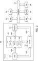
- FIG. 2 is a block diagram illustrating an example processor 300 according to principles of the present disclosure.
- Processor 300 may be used to implement one or more processors described herein, for example, image processor 236 shown in FIG. 1 .
- Processor 300 may be any suitable processor type including, but not limited to, a microprocessor, a microcontroller, a digital signal processor (DSP), a field programmable array (FPGA) where the FPGA has been programmed to form a processor, a graphical processing unit (GPU), an application specific circuit (ASIC) where the ASIC has been designed to form a processor, or a combination thereof.
- DSP digital signal processor
- FPGA field programmable array
- GPU graphical processing unit
- ASIC application specific circuit
- the processor 300 may include one or more cores 302.
- the core 302 may include one or more arithmetic logic units (ALU) 804.
- ALU arithmetic logic unit
- the core 302 may include a floating-point logic unit (FPLU) 306 and/or a digital signal processing unit (DSPU) 308 in addition to or instead of the ALU 304.
- FPLU floating-point logic unit
- DSPU digital signal processing unit
- the processor 300 may include one or more registers 312 communicatively coupled to the core 302.
- the registers 312 may be implemented using dedicated logic gate circuits (e.g., flip-flops) and/or any memory technology. In some examples the registers 312 may be implemented using static memory.
- the register may provide data, instructions and addresses to the core 302.
- processor 300 may include one or more levels of cache memory 310 communicatively coupled to the core 302.
- the cache memory 310 may provide computer-readable instructions to the core 302 for execution.
- the cache memory 810 may provide data for processing by the core 302.
- the computer-readable instructions may have been provided to the cache memory 310 by a local memory, for example, local memory attached to the external bus 316.
- the cache memory 310 may be implemented with any suitable cache memory type, for example, metal-oxide semiconductor (MOS) memory such as static random-access memory (SRAM), dynamic random-access memory (DRAM), and/or any other suitable memory technology.
- MOS metal-oxide semiconductor
- the processor 300 may include a controller 314, which may control input to the processor 300 from other processors and/or components included in a system (e.g., control panel 252 and scan converter 230 shown in FIG. 1 ) and/or outputs from the processor 300 to other processors and/or components included in the system (e.g., display 238 and volume renderer 234 shown in FIG. 1 ).
- Controller 314 may control the data paths in the ALU 304, FPLU 306 and/or DSPU 308.
- Controller 314 may be implemented as one or more state machines, data paths and/or dedicated control logic.
- the gates of controller 314 may be implemented as standalone gates, FPGA, ASIC or any other suitable technology.
- the registers 312 and the cache 310 may communicate with controller 314 and core 302 via internal connections 320A, 320B, 320C and 320D.
- Internal connections may be implemented as a bus, multiplexor, crossbar switch, and/or any other suitable connection technology.
- Inputs and outputs for the processor 300 may be provided via a bus 316, which may include one or more conductive lines.
- the bus 316 may be communicatively coupled to one or more components of processor 300, for example the controller 314, cache 310, and/or register 312.
- the bus 316 may be coupled to one or more components of the system, such as display 238 and control panel 252 mentioned previously.
- the bus 316 may be coupled to one or more external memories.
- the external memories may include Read Only Memory (ROM) 332.
- ROM 332 may be a masked ROM, Electronically Programmable Read Only Memory (EPROM) or any other suitable technology.
- the external memory may include Random Access Memory (RAM) 333.
- RAM 333 may be a static RAM, battery backed up static RAM, Dynamic RAM (DRAM) or any other suitable technology.
- the external memory may include Electrically Erasable Programmable Read Only Memory (EEPROM) 335.
- the external memory may include Flash memory 334.
- the external memory may include a magnetic storage device such as disc 336.
- the external memories may be included in a system, such as ultrasound imaging system 200 shown in Fig. 2 , for example local memory 242.
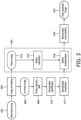
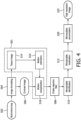
- FIGS. 3 and 4 are flow charts 400, 500 that illustrate steps of methods performed by an image processor, such as image processor 236 shown in FIG. 1 , to perform methods in accordance with examples of the present disclosure.
- the steps in both flow charts 400, 500 are the same, but may be performed in different orders as will be described in detail below.
- a multi-frame loop (formats can be DICOM, AVI, WMV, JPEG, etc.) of conventional side-by-side contrast and tissue images may be used as inputs to the signal processor as indicated by blocks 402 and 502.
- the image-domain-based processing may be implemented as an off-line processing feature in some examples.
- the images may be log-compressed with a limited dynamic range, thus, the image-domain implementation of enhanced CAI may have limited performance.
- enhanced CAI may also be implemented at IQ-domain (input is IQ data) or RF-domain (input is RF data) rather than a multi-frame loop as shown in FIGS. 3 and 4 .
- IQ data and/or RF data may provide better performance of microbubble localization and clutter rejection.
- the image processor may receive data from a signal processor and/or beamformer, such as signal processor 226 and/or beamformer 222 shown in FIG. 1 .
- the steps shown in FIGS. 3 and 4 may be performed by the signal processor.
- the image processor may perform image formatting.
- the multi-frame loops are processed to separate the tissue and contrast images so that they can be processed independently as indicated by blocks 406 and 506 and blocks 414 and 514.
- the tissue and contrast images may be properly formatted for following processing blocks.
- red-green-blue (RGB) images may be converted to gray-scale images (or indexed images) with a desired dynamic range (e.g., normalized from 0 to 1).
- image formatting may include separating signals resultant from the contrast agent and signals resultant from the tissue.
- clutter rejection filtering may be performed on contrast images prior to temporal accumulation, which may reduce the effect of stationary echoes (especially in the near field), reverbs, etc.
- Clutter rejection filters can be implemented as finite impulse response (FIR), infinite impulse response (IIR)-based high-pass filters with sufficient numbers of coefficient delay pairs (e.g., taps), a polynomial least-squares curve fitting filter, and/or singular value decomposition (SVD)-based high-pass filter. Filter parameters may be optimized to suppress most of the residual clutter but preserve most of the contrast signals.
- blocks 408 and 508 may be omitted.
- microbubble identification is performed. Separable individual microbubbles may be identified in this step.
- An optional interpolation step can be performed to bring the image pixel size to a desired resolution (e.g. 50 ⁇ m ⁇ 50 ⁇ m) in some examples.
- an intensity-based thresholding may be performed to remove background noise. For example, normalized intensities less than the threshold (e.g. 35% of maximum intensity) may be considered background noise and set to zero. Additionally, a local maxima search may be performed to find the locations of microbubbles.
- microbubbles may be identified by methods similar to those described above with reference to generating SRI images.
- microbubble localization may be performed. Localization refers to generating the visual representation of each identified microbubble (e.g., multi-pixel spot), which may be established in this step.
- the identified microbubbles are passed through a filter that applies a threshold value or other algorithm for selecting which pixels of the microbubbles to visualize.
- a threshold value e.g. 70%, 80%, 90% of maximum intensity of the microbubble
- a threshold may be pre-defined based on different imaging settings or exam-type based presets. Typically, the threshold is less than 100% and greater than 50% of the maximum intensity of the microbubble. This threshold can be used to adjust the spatial resolution.
- the pixels may be defined as the representation of the microbubble.
- the filter may include other algorithms or operators for selecting pixels for visualization. For example, the filter may select a certain percentage of pixels whose intensity is greater than a mean signal intensity of the microbubble, all microbubbles, or image.
- different intensity values may be assigned to different pixels of the microbubble representation (e.g., visualization).
- the pixel intensities within the microbubble representation remain unchanged and the rest of the microbubble pixel intensities (e.g., the portions of the microbubbles not visualized) may be set to zero.
- Different algorithms for value assignment may be implemented in other examples.
- all of the pixels of the microbubble above the threshold value may be set to a uniform intensity value in some examples.
- the uniform intensity may be based on an average intensity of the pixels above the threshold value or a maximum intensity of the pixels above the threshold value in some examples.
- Motion compensation may be performed before microbubble accumulation. As shown by dashed boxes 401 and 501, motion compensation may be provided at different points in the process of enhanced CAI in various examples of the present disclosure.
- the tissue images 414 and 514 may be used for motion compensation. That is, movement of tissue structures in the tissue images 414 and 514 may be used to estimate displacements due to motion.
- the motion compensation on contrast images alone may be used. If there is not much motion in the multi-frame loop 402, contrast images may be used alone for enhanced CAI, bypassing the tissue image pathway in box 401 as shown in FIG. 3 . However, in some applications, using only the contrast images may be less reliable.
- motion compensation is performed after microbubble localization.
- estimated displacements from the tissue images 414 are performed.
- the estimated displacements calculated at block 416 may be used to compensate for motion in the outputs of the microbubble localization step shown in block 412.
- motion compensation may be performed prior to microbubble identification.
- the dashed box 501 of FIG. 4 shows the estimated displacements from the tissue images 514 calculated at block 516 are used to compensate for motion on the contrast images at block 518 before microbubble localization is performed at block 510.
- the method shown in FIG. 4 may allow for motion compensated contrast images for display.
- the method shown in FIG. 3 may reduce the computational cost of motion compensation, but may come at the expense of not providing motion compensated contrast images for display.
- microbubble accumulation is performed at blocks 410 and 520.
- a high-resolution image 422 and 522 is output from the accumulation step.
- accumulation may be performed by summing multiple image frames from the multi-frame loop, for example, sequential image frames.
- multiple frames may be summed followed by a normalization step.
- multiple frames may be analyzed to determine the maximum pixel intensity for each location in the image may be determined and the maximum pixel intensity values may be used to generate the final image 522.
- the processed ultrasound signals from multiple transmit/receive events may be summed or otherwise combined. The combined ultrasound signals may then be provided to other processing components (e.g., B-mode processor, scan converter) for generating a final image.
- FIG. 5 shows example CAI, enhanced CAI, and SRI images of a flow phantom.
- the conventional CAI image is shown in pane (a).
- the enhanced CAI image in accordance with examples of the present disclosure is shown in pane (b), and the SRI is shown in pane (c).
- the data acquisition time was 180s and the frame rate was 12Hz.
- the enhanced CAI image in pane (b) shows better spatial resolution and better CTR compared to conventional CAI in pane (a).
- SRI image shown in pane (c) has many "holes" in visualizing the phantom vessels and the phantom vessels are not completely filled.
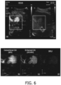
- FIG. 6 shows example in vivo images of a human liver.
- Pane (a) shows side-by-side contrast (left side) and tissue images (right side).
- Pane (b) shows a conventional CAI image
- pane (c) shows an enhanced CAI image in accordance with examples described herein
- pane (d) shows an SRI image.
- the data acquisition time was 17s and the frame rate was 17Hz. There was significant respiratory motion of the liver in this example.
- enhanced CAI image shows better spatial resolution compared to conventional CAI shown in pane (b).
- SRI image shown in pane (d) is not properly formed due to bad filling with many "holes”.
- FIGS. 5 and 6 demonstrate the potential advantages of the proposed systems and methods described herein (e.g., enhanced CAI): better spatial resolution compared to conventional CAI, ability to use regular CEUS frame rates, and/or shorter data acquisition time relative to SRI. Furthermore, the systems and methods described herein allow uses to adjust the representation of the microbubbles (e.g., the number of pixels) to control the spatial resolution of the images. This may give users more control over the trade-offs between resolution and acquisition time.
- the representation of the microbubbles e.g., the number of pixels
- a programmable device such as a computer-based system or programmable logic
- the above-described systems and methods can be implemented using any of various known or later developed programming languages, such as "C”, “C++”, “FORTRAN”, “Pascal”, “VHDL” and the like.
- various storage media such as magnetic computer disks, optical disks, electronic memories and the like, can be prepared that can contain information that can direct a device, such as a computer, to implement the above-described systems and/or methods.
- the storage media can provide the information and programs to the device, thus enabling the device to perform functions of the systems and/or methods described herein.
- the computer could receive the information, appropriately configure itself and perform the functions of the various systems and methods outlined in the diagrams and flowcharts above to implement the various functions. That is, the computer could receive various portions of information from the disk relating to different elements of the above-described systems and/or methods, implement the individual systems and/or methods and coordinate the functions of the individual systems and/or methods described above.
- processors described herein can be implemented in hardware, software, and/or firmware. Further, the various methods and parameters are included by way of example only and not in any limiting sense. In view of this disclosure, those of ordinary skill in the art can implement the present teachings in determining their own techniques and needed equipment to affect these techniques, while remaining within the scope of the invention.
- the functionality of one or more of the processors described herein may be incorporated into a fewer number or a single processing unit (e.g., a CPU) and may be implemented using application specific integrated circuits (ASICs) or general-purpose processing circuits which are programmed responsive to executable instructions to perform the functions described herein.
- ASICs application specific integrated circuits
- the present system may have been described with particular reference to an ultrasound imaging system, it is also envisioned that the present system can be extended to other medical imaging systems where one or more images are obtained in a systematic manner. Accordingly, the present system may be used to obtain and/or record image information related to, but not limited to renal, testicular, breast, ovarian, uterine, thyroid, hepatic, lung, musculoskeletal, splenic, cardiac, arterial and vascular systems, as well as other imaging applications related to ultrasound-guided interventions. Further, the present system may also include one or more programs which may be used with conventional imaging systems so that they may provide features and advantages of the present system.
Landscapes
- Health & Medical Sciences (AREA)
- Life Sciences & Earth Sciences (AREA)
- Engineering & Computer Science (AREA)
- Physics & Mathematics (AREA)
- Surgery (AREA)
- Animal Behavior & Ethology (AREA)
- Radiology & Medical Imaging (AREA)
- Nuclear Medicine, Radiotherapy & Molecular Imaging (AREA)
- Biomedical Technology (AREA)
- Heart & Thoracic Surgery (AREA)
- Medical Informatics (AREA)
- Molecular Biology (AREA)
- Biophysics (AREA)
- Pathology (AREA)
- General Health & Medical Sciences (AREA)
- Public Health (AREA)
- Veterinary Medicine (AREA)
- Computer Vision & Pattern Recognition (AREA)
- General Physics & Mathematics (AREA)
- Theoretical Computer Science (AREA)
- Hematology (AREA)
- Vascular Medicine (AREA)
- Multimedia (AREA)
- Ultra Sonic Daignosis Equipment (AREA)
Claims (15)
- Ultraschallbildgebungssystem (200), umfassend:eine Ultraschallsonde (212) zum Empfangen von Ultraschallsignalen für eine Vielzahl von Sende-/Empfangsereignissen; undmindestens einen Prozessor in Kommunikation mit der Ultraschallsonde, wobei der mindestens eine Prozessor konfiguriert ist, um:Mikrobläschen in den Ultraschallsignalen für die Vielzahl von Sende-/Empfangsereignissen zu identifizieren;einzelne der identifizierten Mikrobläschen als einen Mehrpixelpunkt darzustellen, welcher eine Vielzahl von Pixeln umfasst, wobei die Anzahl der Vielzahl von Pixeln für einzelne der identifizierten Mikrobläschen kleiner als eine Anzahl von Pixeln repräsentativ für die gesamte Ausdehnung des identifizierten Mikrobläschens gemäß einer Punktstreufunktion des Ultraschallbildgebungssystems, und größer als ein einzelnes Pixel ist; unddie Ultraschallsignale, welche die dargestellten Mikrobläschen für die Vielzahl von Sende-/Empfangsereignissen beinhalten, zu kombinieren, um ein Ansammlungsbild mit verstärktem Kontrast zu erzeugen, und dadurch gekennzeichnet, dass:der Prozessor konfiguriert ist, um die einzelnen der identifizierten Mikrobläschen durch Durchleiten der identifizierten Mikrobläschen durch einen Filter, welcher einen Intensitätsschwellenwert zum Auswählen anwendet, welche Pixel der Mikrobläschen zu visualisieren sind, als Mehrpixelpunkte darzustellen, wobei der Filter auf dem Bereich von Intensitäten basiert, welche in jedem identifizierten Mikrobläschen präsentiert sind, und wobei nur Pixel der identifizierten Mikrobläschen über dem Schwellenwert in den einzelnen der Vielzahl von Ultraschallbildern dargestellt werden.
- Ultraschallsystem (200) nach Anspruch 1, wobei die Anzahl der Vielzahl von Pixeln mindestens teilweise auf einem auf die Ultraschallsignale angewendeten Filter basiert.
- Ultraschallbildgebungssystem (200) nach Anspruch 2, welches weiter eine Benutzerschnittstelle umfasst, welche konfiguriert ist, um eine Benutzereingabe zu empfangen, wobei die Benutzereingabe den Schwellenwert beinhaltet.
- Ultraschallbildgebungssystem (200) nach Anspruch 1, wobei der mindestens eine Prozessor konfiguriert ist, um eine Vielzahl von Ultraschallbildern zu bilden, welche den Ultraschallsignalen der Vielzahl von Sende-/Empfangsereignissen entsprechen,
wobei der mindestens eine Prozessor konfiguriert ist, um Mikrobläschen in den Ultraschallsignalen zu identifizieren, nachdem die Ultraschallsignale zum Bilden der Vielzahl von Ultraschallbildern verwendet worden sind. - Ultraschallbildgebungssystem (200) nach Anspruch 4, wobei der mindestens eine Prozessor konfiguriert ist, um die Vielzahl von Ultraschallbildern zu analysieren, um Ultraschallsignale, welche aus Gewebestrukturen resultieren, und Ultraschallsignale, welche aus den Mikrobläschen resultieren, zu trennen, bevor Mikrobläschen identifiziert werden.
- Ultraschallbildgebungssystem (200) nach Anspruch 1, wobei der mindestens eine Prozessor weiter konfiguriert ist, um einen Störsignalunterdrückungsfilter auf die Ultraschallsignale anzuwenden, wobei der Störsignalunterdrückungsfilter mindestens einen von einem Hochpassfilter mit endlicher Impulsantwort, einem Hochpassfilter mit unendlicher Impulsantwort, einem polynomischen Kurvenanpassungsfilter mit kleinsten Quadraten oder einem Hochpassfilter mit Singulärwertzerlegung beinhaltet.
- Ultraschallbildgebungssystem nach Anspruch 1, wobei der mindestens eine Prozessor konfiguriert ist, um Bewegungskompensation durchzuführen.
- Ultraschallbildgebungssystem nach Anspruch 7, wobei die Bewegungskompensation an den dargestellten Mikrobläschen durchgeführt wird.
- Ultraschallbildgebungssystem nach Anspruch 7, wobei der mindestens eine Prozessor konfiguriert ist, um eine Vielzahl von Ultraschallbildern zu bilden, welche den Ultraschallsignalen der Vielzahl von Sende-/Empfangsereignissen entsprechen, und wobei die Bewegungsschätzung und -kompensation an der Vielzahl von Ultraschallbildern durchgeführt wird.
- Ultraschallbildgebungsverfahren, umfassend:Empfangen (402, 502) einer Vielzahl von Ultraschallbildern;Identifizieren (410, 510) von Mikrobläschen in einzelnen der Vielzahl von Ultraschallbildern;Darstellen (412, 512) der identifizierten Mikrobläschen als einen Mehrpixelpunkt, welcher eine Vielzahl von Pixeln umfasst, wobei die Anzahl der Vielzahl von Pixeln von einzelnen der identifizierten Mikrobläschen kleiner als eine Anzahl von Pixeln repräsentativ für die gesamte Ausdehnung des identifizierten Mikrobläschens gemäß einer Punktstreufunktion, und größer als ein einzelnes Pixel ist; undKombinieren von mindestens zwei der einzelnen der Vielzahl von Ultraschallbildern, um ein Ansammlungsbild mit verstärktem Kontrast bereitzustellen, und dadurch gekennzeichnet, dass:
der Schritt des Darstellens Durchleiten der identifizierten Mikrobläschen durch einen Filter umfasst, welcher einen Intensitätsschwellenwert zum Auswählen anwendet, welche Pixel der Mikrobläschen zu visualisieren sind, wobei der Filter auf dem in jedem identifizierten Mikrobläschen präsentierten Bereich von Intensitäten basiert und, wobei nur Pixel der identifizierten Mikrobläschen über dem Schwellenwert in den einzelnen der Vielzahl von Ultraschallbildern dargestellt werden. - Verfahren nach Anspruch 10, wobei Identifizieren der Mikrobläschen Durchführen einer lokalen Maximasuche an einzelnen der Vielzahl von Ultraschallbildern umfasst.
- Verfahren nach Anspruch 11, wobei innerhalb eines durch die Punktstreufunktion definierten Bereichs nur ein lokales Maximum gefunden werden kann.
- Verfahren nach Anspruch 10, weiter umfassend:Schätzen von Verschiebungen aufgrund von Bewegung nach Darstellen der identifizierten Mikrobläschen; undAnpassen von Stellen der dargestellten Mikrobläschen basierend auf den geschätzten Verschiebungen.
- Verfahren nach Anspruch 10, weiter umfassend:Schätzen von Verschiebungen aufgrund von Bewegung vor Identifizieren der Mikrobläschen in den einzelnen der Vielzahl von Ultraschallbildern; undAnpassen der einzelnen der Vielzahl von Ultraschallbildern basierend auf den geschätzten Verschiebungen.
- Verfahren nach Anspruch 14, wobei Bewegung von Gewebestrukturen in den einzelnen der Vielzahl von Ultraschallbildern verwendet wird, um die Verschiebungen zu schätzen.
Applications Claiming Priority (3)
| Application Number | Priority Date | Filing Date | Title |
|---|---|---|---|
| US201962787860P | 2019-01-03 | 2019-01-03 | |
| US201962880107P | 2019-07-30 | 2019-07-30 | |
| PCT/EP2019/086894 WO2020141127A1 (en) | 2019-01-03 | 2019-12-23 | Systems and methods for contrast enhanced imaging |
Publications (2)
| Publication Number | Publication Date |
|---|---|
| EP3905960A1 EP3905960A1 (de) | 2021-11-10 |
| EP3905960B1 true EP3905960B1 (de) | 2024-09-25 |
Family
ID=69063796
Family Applications (1)
| Application Number | Title | Priority Date | Filing Date |
|---|---|---|---|
| EP19829620.4A Active EP3905960B1 (de) | 2019-01-03 | 2019-12-23 | Systeme und verfahren zur kontrastverstärkten bildgebung |
Country Status (5)
| Country | Link |
|---|---|
| US (1) | US12564381B2 (de) |
| EP (1) | EP3905960B1 (de) |
| JP (1) | JP7606662B2 (de) |
| CN (1) | CN113260314B (de) |
| WO (1) | WO2020141127A1 (de) |
Families Citing this family (14)
| Publication number | Priority date | Publication date | Assignee | Title |
|---|---|---|---|---|
| WO2021084060A1 (en) | 2019-11-01 | 2021-05-06 | Koninklijke Philips N.V. | Systems and methods for vascular imaging |
| CN111588409B (zh) * | 2020-05-18 | 2023-04-07 | 南京超维景生物科技有限公司 | 三维超声造影图像的超分辨重建方法及装置 |
| CN111598965B (zh) * | 2020-05-18 | 2023-07-14 | 南京超维景生物科技有限公司 | 超声造影图像的超分辨重建预处理方法和超分辨重建方法 |
| US11403732B2 (en) * | 2020-06-25 | 2022-08-02 | B-K Medical Aps | Ultrasound super resolution imaging |
| US20220211352A1 (en) * | 2021-01-06 | 2022-07-07 | GE Precision Healthcare LLC | System and method for utilizing deep learning techniques to enhance color doppler signals |
| JP2024519328A (ja) * | 2021-06-02 | 2024-05-10 | デンマークス テクニスク ユニヴェルジテイト | 超解像度超音波イメージング |
| US20240268793A1 (en) * | 2021-06-02 | 2024-08-15 | Danmarks Tekniske Universitet | Super resolution ultrasound imaging |
| CN113842130B (zh) * | 2021-09-24 | 2022-03-25 | 刘明明 | 一种生物组织微循环功能参数数据的同步处理及协同分析方法 |
| CN218186818U (zh) * | 2022-04-08 | 2023-01-03 | 深圳迈瑞生物医疗电子股份有限公司 | 一种超声成像系统 |
| CN114463653B (zh) * | 2022-04-12 | 2022-06-28 | 浙江大学 | 一种高浓度微群泡形态识别及轨迹追踪测速方法 |
| CN114903519B (zh) * | 2022-04-19 | 2026-03-24 | 深圳迈瑞生物医疗电子股份有限公司 | 超声波成像方法、超声成像设备及图像显示装置 |
| CN116115268B (zh) * | 2023-02-14 | 2025-09-16 | 西安交通大学 | 一种新型的快速超声超分辨成像方法、系统、设备及介质 |
| US20240350115A1 (en) * | 2023-04-21 | 2024-10-24 | Iconeus | Method and apparatus for backscattering imaging vascular activity at a microscopic scale |
| CN120392162B (zh) * | 2025-07-01 | 2025-09-23 | 合肥综合性国家科学中心人工智能研究院(安徽省人工智能实验室) | 通用的b超成像空间分辨率建模方法和系统 |
Family Cites Families (19)
| Publication number | Priority date | Publication date | Assignee | Title |
|---|---|---|---|---|
| US6210332B1 (en) * | 1998-03-31 | 2001-04-03 | General Electric Company | Method and apparatus for flow imaging using coded excitation |
| US6530885B1 (en) | 2000-03-17 | 2003-03-11 | Atl Ultrasound, Inc. | Spatially compounded three dimensional ultrasonic images |
| US6368277B1 (en) * | 2000-04-05 | 2002-04-09 | Siemens Medical Solutions Usa, Inc. | Dynamic measurement of parameters within a sequence of images |
| US6443896B1 (en) | 2000-08-17 | 2002-09-03 | Koninklijke Philips Electronics N.V. | Method for creating multiplanar ultrasonic images of a three dimensional object |
| EP2208182B1 (de) * | 2007-11-14 | 2011-06-08 | Koninklijke Philips Electronics N.V. | System und verfahren für 3d-ceus-analysen |
| WO2009130647A1 (en) * | 2008-04-24 | 2009-10-29 | Koninklijke Philips Electronics N.V. | Motion compensated micro-vasculature imaging |
| FR2969350B1 (fr) | 2010-12-16 | 2013-01-11 | Centre Nat Rech Scient | Procede et dispositif d'imagerie sonore. |
| US10258314B2 (en) | 2013-05-03 | 2019-04-16 | Sunnybrook Research Institute | Systems and methods for super-resolution ultrasound imaging |
| JP6382995B2 (ja) * | 2014-01-23 | 2018-08-29 | コーニンクレッカ フィリップス エヌ ヴェKoninklijke Philips N.V. | コントラスト強調超音波撮像を用いた頸動脈プラークの評価 |
| GB2551376A (en) | 2016-06-16 | 2017-12-20 | Imperial Innovations Ltd | Acoustic sub-aperture processing for ultrasound imaging |
| JP6866080B2 (ja) * | 2016-07-26 | 2021-04-28 | キヤノンメディカルシステムズ株式会社 | 医用画像処理装置及び医用画像処理プログラム |
| GB201614950D0 (en) * | 2016-09-02 | 2016-10-19 | Ntnu Tech Transfer As | Enhanced-resolution ultrasound imaging of fluid paths |
| WO2018134729A1 (en) | 2017-01-18 | 2018-07-26 | Technion Research & Development Foundation Ltd. | Sparsity-based ultrasound super-resolution imaging |
| US10702245B2 (en) * | 2017-05-04 | 2020-07-07 | National Tsing Hua University | Method of detecting microbubbles in a vessel |
| US11589840B2 (en) * | 2017-05-31 | 2023-02-28 | Mayo Foundation For Medical Education And Research | Methods for super-resolution ultrasound imaging of microvessels |
| CN107361791B (zh) * | 2017-07-21 | 2020-10-09 | 北京大学 | 一种快速超分辨血流成像方法 |
| GB201716606D0 (en) * | 2017-10-10 | 2017-11-22 | Heriot-Watt Univ | Tracking in ultrasound imaging |
| KR20200043048A (ko) * | 2018-10-17 | 2020-04-27 | 삼성메디슨 주식회사 | 초음파 영상 장치 및 그 제어 방법 |
| US11639897B2 (en) * | 2019-03-29 | 2023-05-02 | Vyv, Inc. | Contamination load sensing device |
-
2019
- 2019-12-23 EP EP19829620.4A patent/EP3905960B1/de active Active
- 2019-12-23 US US17/417,137 patent/US12564381B2/en active Active
- 2019-12-23 JP JP2021537105A patent/JP7606662B2/ja active Active
- 2019-12-23 CN CN201980087675.5A patent/CN113260314B/zh active Active
- 2019-12-23 WO PCT/EP2019/086894 patent/WO2020141127A1/en not_active Ceased
Also Published As
| Publication number | Publication date |
|---|---|
| JP2022515810A (ja) | 2022-02-22 |
| US12564381B2 (en) | 2026-03-03 |
| WO2020141127A1 (en) | 2020-07-09 |
| CN113260314A (zh) | 2021-08-13 |
| US20220071596A1 (en) | 2022-03-10 |
| EP3905960A1 (de) | 2021-11-10 |
| CN113260314B (zh) | 2024-10-01 |
| JP7606662B2 (ja) | 2024-12-26 |
Similar Documents
| Publication | Publication Date | Title |
|---|---|---|
| EP3905960B1 (de) | Systeme und verfahren zur kontrastverstärkten bildgebung | |
| EP4051126B1 (de) | Systeme und verfahren zur vaskulären bildgebung | |
| JP7232195B2 (ja) | 血管内の壁せん断応力の同時視覚化及び定量化のためのシステム及び方法 | |
| US20230329669A1 (en) | System and method for concurrent visualization and quantification of blood flow using ultrasound vector flow imaging | |
| EP4061235B1 (de) | Systeme und verfahren für adaptive kontrastbildgebung | |
| EP3615958B1 (de) | Leistungsdoppler-bildgebungssystem und -verfahren mit verbesserter störechounterdrückung | |
| US11529118B2 (en) | Ultrasound system and method for detection of kidney stones using twinkling artifact | |
| US12462381B2 (en) | Systems and methods for color mappings of contrast images | |
| US12201481B2 (en) | Methods and systems for speckle reduction in ultrasound images by compounding sub-images associated with different receive angles | |
| EP4260276B1 (de) | Vorrichtung und verfahren zur kontrastbildgebung | |
| US20250208277A1 (en) | Systems and methods for color mapping for contrast enhanced ultrasound parametric imaging |
Legal Events
| Date | Code | Title | Description |
|---|---|---|---|
| STAA | Information on the status of an ep patent application or granted ep patent |
Free format text: STATUS: UNKNOWN |
|
| STAA | Information on the status of an ep patent application or granted ep patent |
Free format text: STATUS: THE INTERNATIONAL PUBLICATION HAS BEEN MADE |
|
| PUAI | Public reference made under article 153(3) epc to a published international application that has entered the european phase |
Free format text: ORIGINAL CODE: 0009012 |
|
| STAA | Information on the status of an ep patent application or granted ep patent |
Free format text: STATUS: REQUEST FOR EXAMINATION WAS MADE |
|
| 17P | Request for examination filed |
Effective date: 20210803 |
|
| AK | Designated contracting states |
Kind code of ref document: A1 Designated state(s): AL AT BE BG CH CY CZ DE DK EE ES FI FR GB GR HR HU IE IS IT LI LT LU LV MC MK MT NL NO PL PT RO RS SE SI SK SM TR |
|
| DAV | Request for validation of the european patent (deleted) | ||
| DAX | Request for extension of the european patent (deleted) | ||
| STAA | Information on the status of an ep patent application or granted ep patent |
Free format text: STATUS: EXAMINATION IS IN PROGRESS |
|
| 17Q | First examination report despatched |
Effective date: 20230331 |
|
| GRAP | Despatch of communication of intention to grant a patent |
Free format text: ORIGINAL CODE: EPIDOSNIGR1 |
|
| STAA | Information on the status of an ep patent application or granted ep patent |
Free format text: STATUS: GRANT OF PATENT IS INTENDED |
|
| INTG | Intention to grant announced |
Effective date: 20240426 |
|
| GRAS | Grant fee paid |
Free format text: ORIGINAL CODE: EPIDOSNIGR3 |
|
| GRAA | (expected) grant |
Free format text: ORIGINAL CODE: 0009210 |
|
| STAA | Information on the status of an ep patent application or granted ep patent |
Free format text: STATUS: THE PATENT HAS BEEN GRANTED |
|
| AK | Designated contracting states |
Kind code of ref document: B1 Designated state(s): AL AT BE BG CH CY CZ DE DK EE ES FI FR GB GR HR HU IE IS IT LI LT LU LV MC MK MT NL NO PL PT RO RS SE SI SK SM TR |
|
| REG | Reference to a national code |
Ref country code: GB Ref legal event code: FG4D |
|
| REG | Reference to a national code |
Ref country code: CH Ref legal event code: EP |
|
| REG | Reference to a national code |
Ref country code: DE Ref legal event code: R096 Ref document number: 602019059517 Country of ref document: DE |
|
| REG | Reference to a national code |
Ref country code: IE Ref legal event code: FG4D |
|
| REG | Reference to a national code |
Ref country code: DE Ref legal event code: R084 Ref document number: 602019059517 Country of ref document: DE |
|
| REG | Reference to a national code |
Ref country code: LT Ref legal event code: MG9D |
|
| PG25 | Lapsed in a contracting state [announced via postgrant information from national office to epo] |
Ref country code: NO Free format text: LAPSE BECAUSE OF FAILURE TO SUBMIT A TRANSLATION OF THE DESCRIPTION OR TO PAY THE FEE WITHIN THE PRESCRIBED TIME-LIMIT Effective date: 20241225 |
|
| PG25 | Lapsed in a contracting state [announced via postgrant information from national office to epo] |
Ref country code: GR Free format text: LAPSE BECAUSE OF FAILURE TO SUBMIT A TRANSLATION OF THE DESCRIPTION OR TO PAY THE FEE WITHIN THE PRESCRIBED TIME-LIMIT Effective date: 20241226 Ref country code: FI Free format text: LAPSE BECAUSE OF FAILURE TO SUBMIT A TRANSLATION OF THE DESCRIPTION OR TO PAY THE FEE WITHIN THE PRESCRIBED TIME-LIMIT Effective date: 20240925 |
|
| PG25 | Lapsed in a contracting state [announced via postgrant information from national office to epo] |
Ref country code: BG Free format text: LAPSE BECAUSE OF FAILURE TO SUBMIT A TRANSLATION OF THE DESCRIPTION OR TO PAY THE FEE WITHIN THE PRESCRIBED TIME-LIMIT Effective date: 20240925 |
|
| PG25 | Lapsed in a contracting state [announced via postgrant information from national office to epo] |
Ref country code: LV Free format text: LAPSE BECAUSE OF FAILURE TO SUBMIT A TRANSLATION OF THE DESCRIPTION OR TO PAY THE FEE WITHIN THE PRESCRIBED TIME-LIMIT Effective date: 20240925 |
|
| PG25 | Lapsed in a contracting state [announced via postgrant information from national office to epo] |
Ref country code: RS Free format text: LAPSE BECAUSE OF FAILURE TO SUBMIT A TRANSLATION OF THE DESCRIPTION OR TO PAY THE FEE WITHIN THE PRESCRIBED TIME-LIMIT Effective date: 20241225 |
|
| REG | Reference to a national code |
Ref country code: NL Ref legal event code: MP Effective date: 20240925 |
|
| PG25 | Lapsed in a contracting state [announced via postgrant information from national office to epo] |
Ref country code: RS Free format text: LAPSE BECAUSE OF FAILURE TO SUBMIT A TRANSLATION OF THE DESCRIPTION OR TO PAY THE FEE WITHIN THE PRESCRIBED TIME-LIMIT Effective date: 20241225 Ref country code: NO Free format text: LAPSE BECAUSE OF FAILURE TO SUBMIT A TRANSLATION OF THE DESCRIPTION OR TO PAY THE FEE WITHIN THE PRESCRIBED TIME-LIMIT Effective date: 20241225 Ref country code: LV Free format text: LAPSE BECAUSE OF FAILURE TO SUBMIT A TRANSLATION OF THE DESCRIPTION OR TO PAY THE FEE WITHIN THE PRESCRIBED TIME-LIMIT Effective date: 20240925 Ref country code: GR Free format text: LAPSE BECAUSE OF FAILURE TO SUBMIT A TRANSLATION OF THE DESCRIPTION OR TO PAY THE FEE WITHIN THE PRESCRIBED TIME-LIMIT Effective date: 20241226 Ref country code: FI Free format text: LAPSE BECAUSE OF FAILURE TO SUBMIT A TRANSLATION OF THE DESCRIPTION OR TO PAY THE FEE WITHIN THE PRESCRIBED TIME-LIMIT Effective date: 20240925 Ref country code: BG Free format text: LAPSE BECAUSE OF FAILURE TO SUBMIT A TRANSLATION OF THE DESCRIPTION OR TO PAY THE FEE WITHIN THE PRESCRIBED TIME-LIMIT Effective date: 20240925 |
|
| REG | Reference to a national code |
Ref country code: AT Ref legal event code: MK05 Ref document number: 1725982 Country of ref document: AT Kind code of ref document: T Effective date: 20240925 |
|
| PG25 | Lapsed in a contracting state [announced via postgrant information from national office to epo] |
Ref country code: NL Free format text: LAPSE BECAUSE OF FAILURE TO SUBMIT A TRANSLATION OF THE DESCRIPTION OR TO PAY THE FEE WITHIN THE PRESCRIBED TIME-LIMIT Effective date: 20240925 |
|
| PG25 | Lapsed in a contracting state [announced via postgrant information from national office to epo] |
Ref country code: PT Free format text: LAPSE BECAUSE OF FAILURE TO SUBMIT A TRANSLATION OF THE DESCRIPTION OR TO PAY THE FEE WITHIN THE PRESCRIBED TIME-LIMIT Effective date: 20250127 Ref country code: IS Free format text: LAPSE BECAUSE OF FAILURE TO SUBMIT A TRANSLATION OF THE DESCRIPTION OR TO PAY THE FEE WITHIN THE PRESCRIBED TIME-LIMIT Effective date: 20250125 |
|
| PG25 | Lapsed in a contracting state [announced via postgrant information from national office to epo] |
Ref country code: RO Free format text: LAPSE BECAUSE OF FAILURE TO SUBMIT A TRANSLATION OF THE DESCRIPTION OR TO PAY THE FEE WITHIN THE PRESCRIBED TIME-LIMIT Effective date: 20240925 Ref country code: SM Free format text: LAPSE BECAUSE OF FAILURE TO SUBMIT A TRANSLATION OF THE DESCRIPTION OR TO PAY THE FEE WITHIN THE PRESCRIBED TIME-LIMIT Effective date: 20240925 |
|
| PG25 | Lapsed in a contracting state [announced via postgrant information from national office to epo] |
Ref country code: ES Free format text: LAPSE BECAUSE OF FAILURE TO SUBMIT A TRANSLATION OF THE DESCRIPTION OR TO PAY THE FEE WITHIN THE PRESCRIBED TIME-LIMIT Effective date: 20240925 |
|
| PG25 | Lapsed in a contracting state [announced via postgrant information from national office to epo] |
Ref country code: EE Free format text: LAPSE BECAUSE OF FAILURE TO SUBMIT A TRANSLATION OF THE DESCRIPTION OR TO PAY THE FEE WITHIN THE PRESCRIBED TIME-LIMIT Effective date: 20240925 Ref country code: AT Free format text: LAPSE BECAUSE OF FAILURE TO SUBMIT A TRANSLATION OF THE DESCRIPTION OR TO PAY THE FEE WITHIN THE PRESCRIBED TIME-LIMIT Effective date: 20240925 |
|
| PG25 | Lapsed in a contracting state [announced via postgrant information from national office to epo] |
Ref country code: PL Free format text: LAPSE BECAUSE OF FAILURE TO SUBMIT A TRANSLATION OF THE DESCRIPTION OR TO PAY THE FEE WITHIN THE PRESCRIBED TIME-LIMIT Effective date: 20240925 Ref country code: CZ Free format text: LAPSE BECAUSE OF FAILURE TO SUBMIT A TRANSLATION OF THE DESCRIPTION OR TO PAY THE FEE WITHIN THE PRESCRIBED TIME-LIMIT Effective date: 20240925 |
|
| PG25 | Lapsed in a contracting state [announced via postgrant information from national office to epo] |
Ref country code: IT Free format text: LAPSE BECAUSE OF FAILURE TO SUBMIT A TRANSLATION OF THE DESCRIPTION OR TO PAY THE FEE WITHIN THE PRESCRIBED TIME-LIMIT Effective date: 20240925 Ref country code: SK Free format text: LAPSE BECAUSE OF FAILURE TO SUBMIT A TRANSLATION OF THE DESCRIPTION OR TO PAY THE FEE WITHIN THE PRESCRIBED TIME-LIMIT Effective date: 20240925 |
|
| REG | Reference to a national code |
Ref country code: DE Ref legal event code: R097 Ref document number: 602019059517 Country of ref document: DE |
|
| PG25 | Lapsed in a contracting state [announced via postgrant information from national office to epo] |
Ref country code: MC Free format text: LAPSE BECAUSE OF FAILURE TO SUBMIT A TRANSLATION OF THE DESCRIPTION OR TO PAY THE FEE WITHIN THE PRESCRIBED TIME-LIMIT Effective date: 20240925 |
|
| PG25 | Lapsed in a contracting state [announced via postgrant information from national office to epo] |
Ref country code: DK Free format text: LAPSE BECAUSE OF FAILURE TO SUBMIT A TRANSLATION OF THE DESCRIPTION OR TO PAY THE FEE WITHIN THE PRESCRIBED TIME-LIMIT Effective date: 20240925 |
|
| REG | Reference to a national code |
Ref country code: CH Ref legal event code: PL |
|
| PLBE | No opposition filed within time limit |
Free format text: ORIGINAL CODE: 0009261 |
|
| STAA | Information on the status of an ep patent application or granted ep patent |
Free format text: STATUS: NO OPPOSITION FILED WITHIN TIME LIMIT |
|
| PG25 | Lapsed in a contracting state [announced via postgrant information from national office to epo] |
Ref country code: LU Free format text: LAPSE BECAUSE OF NON-PAYMENT OF DUE FEES Effective date: 20241223 |
|
| 26N | No opposition filed |
Effective date: 20250626 |
|
| PG25 | Lapsed in a contracting state [announced via postgrant information from national office to epo] |
Ref country code: SE Free format text: LAPSE BECAUSE OF FAILURE TO SUBMIT A TRANSLATION OF THE DESCRIPTION OR TO PAY THE FEE WITHIN THE PRESCRIBED TIME-LIMIT Effective date: 20240925 |
|
| REG | Reference to a national code |
Ref country code: BE Ref legal event code: MM Effective date: 20241231 |
|
| PG25 | Lapsed in a contracting state [announced via postgrant information from national office to epo] |
Ref country code: BE Free format text: LAPSE BECAUSE OF NON-PAYMENT OF DUE FEES Effective date: 20241231 |
|
| PG25 | Lapsed in a contracting state [announced via postgrant information from national office to epo] |
Ref country code: FR Free format text: LAPSE BECAUSE OF NON-PAYMENT OF DUE FEES Effective date: 20241231 |
|
| PG25 | Lapsed in a contracting state [announced via postgrant information from national office to epo] |
Ref country code: CH Free format text: LAPSE BECAUSE OF NON-PAYMENT OF DUE FEES Effective date: 20241231 |
|
| PG25 | Lapsed in a contracting state [announced via postgrant information from national office to epo] |
Ref country code: IE Free format text: LAPSE BECAUSE OF NON-PAYMENT OF DUE FEES Effective date: 20241223 |
|
| PGFP | Annual fee paid to national office [announced via postgrant information from national office to epo] |
Ref country code: GB Payment date: 20251223 Year of fee payment: 7 |
|
| PG25 | Lapsed in a contracting state [announced via postgrant information from national office to epo] |
Ref country code: HR Free format text: LAPSE BECAUSE OF FAILURE TO SUBMIT A TRANSLATION OF THE DESCRIPTION OR TO PAY THE FEE WITHIN THE PRESCRIBED TIME-LIMIT Effective date: 20240925 |
|
| PGFP | Annual fee paid to national office [announced via postgrant information from national office to epo] |
Ref country code: DE Payment date: 20251229 Year of fee payment: 7 |