EP3907162B1 - Anlage zur verarbeitung von behältern - Google Patents
Anlage zur verarbeitung von behältern Download PDFInfo
- Publication number
- EP3907162B1 EP3907162B1 EP21166055.0A EP21166055A EP3907162B1 EP 3907162 B1 EP3907162 B1 EP 3907162B1 EP 21166055 A EP21166055 A EP 21166055A EP 3907162 B1 EP3907162 B1 EP 3907162B1
- Authority
- EP
- European Patent Office
- Prior art keywords
- operating portion
- retaining element
- containers
- container
- operating
- Prior art date
- Legal status (The legal status is an assumption and is not a legal conclusion. Google has not performed a legal analysis and makes no representation as to the accuracy of the status listed.)
- Active
Links
Images




Classifications
-
- B—PERFORMING OPERATIONS; TRANSPORTING
- B65—CONVEYING; PACKING; STORING; HANDLING THIN OR FILAMENTARY MATERIAL
- B65G—TRANSPORT OR STORAGE DEVICES, e.g. CONVEYORS FOR LOADING OR TIPPING, SHOP CONVEYOR SYSTEMS OR PNEUMATIC TUBE CONVEYORS
- B65G54/00—Non-mechanical conveyors not otherwise provided for
- B65G54/02—Non-mechanical conveyors not otherwise provided for electrostatic, electric, or magnetic
-
- B—PERFORMING OPERATIONS; TRANSPORTING
- B65—CONVEYING; PACKING; STORING; HANDLING THIN OR FILAMENTARY MATERIAL
- B65G—TRANSPORT OR STORAGE DEVICES, e.g. CONVEYORS FOR LOADING OR TIPPING, SHOP CONVEYOR SYSTEMS OR PNEUMATIC TUBE CONVEYORS
- B65G47/00—Article or material-handling devices associated with conveyors; Methods employing such devices
- B65G47/02—Devices for feeding articles or materials to conveyors
- B65G47/04—Devices for feeding articles or materials to conveyors for feeding articles
-
- B—PERFORMING OPERATIONS; TRANSPORTING
- B65—CONVEYING; PACKING; STORING; HANDLING THIN OR FILAMENTARY MATERIAL
- B65G—TRANSPORT OR STORAGE DEVICES, e.g. CONVEYORS FOR LOADING OR TIPPING, SHOP CONVEYOR SYSTEMS OR PNEUMATIC TUBE CONVEYORS
- B65G47/00—Article or material-handling devices associated with conveyors; Methods employing such devices
- B65G47/74—Feeding, transfer, or discharging devices of particular kinds or types
- B65G47/90—Devices for picking-up and depositing articles or materials
- B65G47/901—Devices for picking-up and depositing articles or materials provided with drive systems with rectilinear movements only
-
- B—PERFORMING OPERATIONS; TRANSPORTING
- B65—CONVEYING; PACKING; STORING; HANDLING THIN OR FILAMENTARY MATERIAL
- B65G—TRANSPORT OR STORAGE DEVICES, e.g. CONVEYORS FOR LOADING OR TIPPING, SHOP CONVEYOR SYSTEMS OR PNEUMATIC TUBE CONVEYORS
- B65G29/00—Rotary conveyors, e.g. rotating discs, arms, star-wheels or cones
-
- B—PERFORMING OPERATIONS; TRANSPORTING
- B65—CONVEYING; PACKING; STORING; HANDLING THIN OR FILAMENTARY MATERIAL
- B65G—TRANSPORT OR STORAGE DEVICES, e.g. CONVEYORS FOR LOADING OR TIPPING, SHOP CONVEYOR SYSTEMS OR PNEUMATIC TUBE CONVEYORS
- B65G47/00—Article or material-handling devices associated with conveyors; Methods employing such devices
- B65G47/22—Devices influencing the relative position or the attitude of articles during transit by conveyors
- B65G47/26—Devices influencing the relative position or the attitude of articles during transit by conveyors arranging the articles, e.g. varying spacing between individual articles
- B65G47/28—Devices influencing the relative position or the attitude of articles during transit by conveyors arranging the articles, e.g. varying spacing between individual articles during transit by a single conveyor
-
- B—PERFORMING OPERATIONS; TRANSPORTING
- B65—CONVEYING; PACKING; STORING; HANDLING THIN OR FILAMENTARY MATERIAL
- B65G—TRANSPORT OR STORAGE DEVICES, e.g. CONVEYORS FOR LOADING OR TIPPING, SHOP CONVEYOR SYSTEMS OR PNEUMATIC TUBE CONVEYORS
- B65G47/00—Article or material-handling devices associated with conveyors; Methods employing such devices
- B65G47/74—Feeding, transfer, or discharging devices of particular kinds or types
- B65G47/84—Star-shaped wheels or devices having endless travelling belts or chains, the wheels or devices being equipped with article-engaging elements
- B65G47/841—Devices having endless travelling belts or chains equipped with article-engaging elements
- B65G47/842—Devices having endless travelling belts or chains equipped with article-engaging elements the article-engaging elements being grippers
-
- B—PERFORMING OPERATIONS; TRANSPORTING
- B65—CONVEYING; PACKING; STORING; HANDLING THIN OR FILAMENTARY MATERIAL
- B65G—TRANSPORT OR STORAGE DEVICES, e.g. CONVEYORS FOR LOADING OR TIPPING, SHOP CONVEYOR SYSTEMS OR PNEUMATIC TUBE CONVEYORS
- B65G2201/00—Indexing codes relating to handling devices, e.g. conveyors, characterised by the type of product or load being conveyed or handled
- B65G2201/02—Articles
- B65G2201/0235—Containers
- B65G2201/0244—Bottles
Definitions
- This invention relates to a plant for processing containers equipped with a conveying device for conveying containers along a movement path between a feeding device for feeding the containers and a pick-up device for picking up the containers.
- the containers to which this invention refers may be of any type and made of any material, such as for example glass bottles, plastic bottles, tins, vials, etc.
- the definition plant for processing containers means any plant intended to perform operations on containers, such as for example washing plants, filling plants, labelling plants, capping plants, boxing plants, packaging plants, etc.
- Each gripping unit is generally configured to retain the container while it moves forward along a movement path.
- the technical purpose which forms the basis of this invention is to make a plant for processing containers, which overcomes the above-mentioned disadvantages.
- the technical purpose of this invention is to make a plant for processing containers which is equipped with a conveying device for conveying containers which at least in its general structure can be easily adapted to containers of any type and size.
- a further technical purpose of this invention is to make a conveying device for conveying containers, which can easily be used in plants for processing containers, for transferring the containers from a first device to a second device.
- the reference numeral 1 denotes in its entirety a conveying device according to this invention, configured to convey containers 2 along a movement path.
- This invention relates to a plant for processing containers 2 which comprises not just the feeding device 1 for feeding the containers 2, but also a pick-up device 3 for picking up the containers 2 and a conveying device 1.
- the appended figures only show the final stretch of the movement path, that is to say, the stretch which ends at the containers pick-up device 3 (arrival station 4), whilst it does not show the initial stretch, that is to say, the one at the feeding device for feeding containers 2 (starting station).
- the conveying device 1 comprises a fixed supporting unit 5, which extends along a trajectory of extension, and which, along part of its length, extends parallel to the movement path.
- the fixed supporting unit 5 defines a sliding rail 6.
- the trajectory of extension is closed.
- At least one gripping unit 7 is slidably associated with the fixed supporting unit 5, for moving along the trajectory of extension.
- the gripping unit 7 moves cyclically along the trajectory of extension, in particular when the latter is closed.
- the conveying device 1 according to this invention comprises a plurality of gripping units 7 mounted one after another on the fixed supporting unit 5.
- each gripping unit 7 is movable independently of the others along the fixed supporting unit 5, meaning, for example, that each unit can move while one or more of the others are stationary, and/or can move with different instantaneous speeds relative to the others.
- the fixed supporting unit 5 is specially configured with multiple parallel paths which allow the gripping units 7 to "overtake” each other, the fact that the gripping units 7 move independently of each other does not mean that they are capable of changing their position relative to each other along the trajectory of extension.
- Each gripping unit 7 is configured to retain and move a container 2 along the movement path.
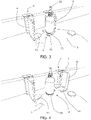
- the gripping unit 7 comprises a first retaining element 8, slidably coupled to the fixed supporting unit 5 and comprising a first operating portion 9, and a second retaining element 10, slidably coupled to the fixed supporting unit 5 and comprising a second operating portion 11.
- each gripping unit 7 is constituted of the assembly consisting of the first retaining element 8 and the second retaining element 10.
- the first operating portion 9 and the second operating portion 11 are configured to define between them a housing 12 for a container 2 to be moved along the movement path, according to the methods explained in detail below.
- the second retaining element 10 is alongside the first retaining element 8, in such a way that the first retaining element 8 and the second retaining element 10 are placed one upstream (after) and one downstream (before) relative to the direction of forward movement along the movement path.
- an operating stretch and a return stretch are identified in it.
- the operating stretch is that in which the gripping unit 7 is located while it moves forward a container 2 along the movement path
- the return stretch is that along which the gripping unit 7 is located while it returns from the end to the start of the operating stretch.
- the first retaining element 8 and the second retaining element 10 are also independently movable along the fixed supporting unit 5. In particular each of them is movable by means of respective linear motor actuators which are part of the conveying device 1.
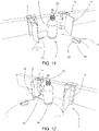
- the first retaining element 8 and the second retaining element 10 are coordinated with each other and, by means of their reciprocal movement, independent but appropriately managed, they can switch their reciprocal configuration between an operating configuration, and a home configuration.
- the first operating portion 9 and the second operating portion 11 are close together and between them define a housing 12 for a container 2
- the first operating portion 9 and the second operating portion 11 are at a distance from each other in such a way as to allow the positioning of a container 2 between them (so that the next switch to the operating configuration can "shut" the container 2 in the housing 12) or to allow a container 2 previously contained in the housing 12 to come out.
- the first operating portion 9 and the second operating portion 11 are positioned alongside the fixed supporting unit 5, below the fixed supporting unit 5, or above it but at a distance from it, in any case sufficient for the space below the housing 12 to remain free.
- the movement path extends between the starting station and the arrival station 4, and at least at the starting station and/or the arrival station 4, the device defines an empty space below the first operating portion 9, the second operating portion 11 (and the supporting portion described below), for allowing the positioning below the gripping unit 7, respectively, of the containers feeding device and/or of the containers pick-up device 3.
- the first operating portion 9 and the second operating portion 11 switch from the home position, to the operating position, at the starting station of the movement path, remain in the operating configuration when the first retaining element 8 and the second retaining element 10 move along the operating stretch of the trajectory of extension, to move forward the container 2 along the movement path, and they switch to the home configuration when at the arrival station 4 of the movement path.
- the first operating portion 9 and the second operating portion 11 are jointly configured in such a way that, when they are in the operating configuration, they at least partly enclose the container 2 preventing it from coming out of the housing 12 sideways.
- both the first operating portion 9 and the second operating portion 11 may have a C, U, L or V shape
- first operating portion 9 and the second operating portion 11 are configured to lock between them the container 2 to be moved, when they are in the operating configuration, preventing movements of the container 2 relative to the housing 12.
- first operating portion 9 and the second operating portion 11 may be configured not to lock between them the container 2 to be moved, when they are in the operating configuration, but to retain it while allowing it the possibility of performing movements relative to the housing 12 (for example rotations about itself).
- first operating portion 9 and the second operating portion 11 may be able to adopt different positions on the respective retaining element 8, 10, and/or for them to be able to change their shape, in order to adapt to containers 2 of different type and size.
- they can adopt different positions, in such a way as to vary their distance from each other in the operating configuration, and/or that the one with the C, U or V shape may change its shape by increasing or reducing the inclination of the inclined zones.
- first retaining element 8 and the second retaining element 10 comprise a plurality of interchangeable operating portions 9, 11, for allowing the management of a plurality of containers 2 having different shape and/or size.
- At least one of the first operating portion 9 or the second operating portion 11 also comprises a supporting portion 13 which, in the operating configuration, constitutes a lower support for a container 2 placed in the housing 12 formed between the first operating portion 9 and the second operating portion 11.
- the supporting portion 13 constitutes at least part of a bottom wall for the housing 12.
- only one of the operating portions 9, 11 comprises the supporting portion 13. In other embodiments, both of the operating portions 9, 11 comprise the supporting portion 13.
- the supporting portions 13 may have complementary shapes and, jointly, at least partly constitute the bottom wall of the housing 12.
- the supporting portion 13 (or each supporting portion 13) may adopt different shapes.
- the supporting portion 13 comprises one or more projections 14 which extend cantilever-style mainly along a direction parallel to the movement path.
- those projections 14, seen in plan view have the appearance of fingers with a cross-section which is constant or decreasing away from the rest of the operating portion to which they are fixed. If both operating portions 9, 11 comprise a supporting portion 13 which has the projections 14, the two supporting portions 13 are advantageously shaped to match each other.
- the supporting portion 13 is also U- or C-shaped and defines a perimetric portion of the bottom wall of the housing 12, intended to support the container 2 at an outer part of the bottom of it. As illustrated for example in Figure 4 and 5 , depending on the embodiments the U or the C may have different dimensions.
- the supporting portion 13 is rigidly connected to the rest of the first operating portion 9 or of the second operating portion 11 of which it is a part.
- the supporting portion 13 is connected to the rest of the first operating portion 9 or of the second operating portion 11 of which it is a part, with one or more degrees of freedom.
- the supporting portion 13 may be movable relative to the rest of the first operating portion 9 or of the second operating portion 11 of which it is a part, around a vertical axis of rotation and/or along a horizontal direction of translation transversal or perpendicular to the movement path.
- Providing a movable supporting portion 13 is particularly advantageous when the movement path follows a curved trajectory, especially if both the first operating portion 9 and the second operating portion 11 comprise a supporting portion 13 and the two supporting portions 13 are coupled to each other.
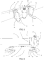
- the supporting portion 13 only partly closes the bottom of the housing 12, that is to say, defining a bottom wall which is incomplete or which has openings 15. That is advantageously implemented in such a way that, in the operating configuration, the housing 12 is partly open at the bottom, to allow the insertion into the housing 12 from below, of units suitable for interacting with the container 2 contained in the housing 12 itself; moreover, preferably, the supporting portion 13 is shaped in such a way that the respective operating portion 9, 11 can be switched between the operating configuration and the home configuration, while those units are inserted into the housing 12 from below and interact with the container 2; for that purpose it is necessary that the open spaces 15 into which those units are inserted are not completely surrounded by the supporting portion 13, instead being laterally open at least at the side directed towards the other operating portion.
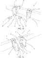
- This embodiment is particularly preferred when such units are units for loading or unloading the container 2 into/from the housing 12, for example as in the embodiment of Figures 6 to 13 .
- the supporting portion 13 is configured to couple to the containers feeding device at the starting station of the movement path, and to the containers pick-up device 3 at the arrival station 4 of the movement path.
- the supporting portion 13, if present, allows respectively the feeding device and/or the pick-up device 3 to interact with the bottom of the container 2, to support it from below respectively during the feeding to the housing 12 and/or during the pick-up from the housing 12.
- the supporting portion 13 is part of the retaining element 8, 10 which is placed after, relative to the direction of forward movement of the container 2 along the movement path.
- the housing 12 is completely open at the bottom and the first operating portion 9 and the second operating portion 11 are configured to lock between them the container 2 to be moved by acting exclusively on a lateral surface of the container 2.
- An example of this type is shown in Figures 15 to 17 , which illustrate two adjacent gripping units 7.
- the first retaining element 8 and the second retaining element 10 of each gripping unit 7 are illustrated clamped on a container 12, whose outer dimensions are the only part of it shown.
- the clamping is caused only by the force that each retaining element 8, 10 applies on the container by means of the first and second operating portions 9, 11.
- a gap will always be present, if necessary even just a few millimetres.
- the conveying device 1 is interposed between the containers feeding device and the containers pick-up device 3, and the movement path extends between a starting station, at the containers feeding device, and an arrival station 4, at the containers pick-up device 3.
- the containers feeding device is coupled to the conveying device 1, in order to position a container 2 between the first operating portion 9 and the second operating portion 11.
- the container 2 is fed directly into the housing 12 formed by the first operating portion 9 and by the second operating portion 11 in the operating configuration (this is possible when the first operating portion 9 and the second operating portion 11 are not configured to lock the container 2 when they are in the operating configuration).
- the conveying device 1 is coupled to the containers pick-up device 3 in order to release, to the pick-up device 3 for picking up containers 2, the container 2 contained in the housing 12.
- the release occurs when the first retaining element 8 and the second retaining element 10 switch from the operating configuration to the home configuration.
- Both the feeding device, and the pick-up device 3 may adopt the most suitable structure depending on requirements. Furthermore, each type of pick-up device 3 may also be used as a feeding device: it is sufficient that in the two cases operation is inverted.
- the feeding device may be constituted of a robotic arm suitable for positioning the container 2 in the correct position, between the first operating portion 9 and the second operating portion 11
- the conveying device 1 is configured to switch the first retaining element 8 and the second retaining element 10 to the operating configuration, while the first operating portion 9 and the second operating portion 11 are still at the starting station, and after the containers feeding device has positioned the container 2 between the first operating portion 9 and the second operating portion 11.
- the switching may occur by adopting specific methods, which allow unwanted movements by the container 2 to be avoided.
- the switching from the home configuration to the operating configuration may advantageously occur by bringing the operating portion 9, 11 without supporting portions 13, to rest on or near to the container 2, and then moving the other operating portion 11, 9 until it reaches the operating configuration, thereby forcing insertion of the supporting portion 13 below the container 2.
- This method of proceeding may be particularly useful if the supporting portion 13 must be forcibly inserted below the container 2.
- the conveying device 1 is in contrast configured to switch the first retaining element 8 and the second retaining element 10 from the operating configuration to the home configuration.
- the containers feeding device and/or the containers pick-up device 3 may comprise a lifting element for lifting the container 2, shaped in such a way that it can be inserted into the housing 12 from below through the spaces left free by the supporting portion 13.
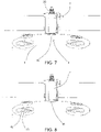
- the feeding device and/or the pick-up device 3 may comprise a supporting plate 16 couplable at the bottom to the gripping unit 7 (respectively in the starting station and/or in the arrival station 4).
- the supporting plate 16 comprises one or more raised or raisable portions, which can be inserted into the housing 12 from below in order to support the container 2 independently of the gripping unit 7.
- the pick-up device 3 is constituted of a plate carrousel 17, in which each supporting plate 16 is vertically movable relative to the carrousel 17, can rotate relative to the carrousel 17 around its own central axis, and can rotated together with the carrousel 17 around the central axis of the carrousel 17.
- the supporting portion 13 has a rectangular plan with the long side significantly larger than the short side, whilst the supporting plate 16 has a circular plan as a whole with a diameter such that it can be inscribed in the housing 12 formed between the first operating portion 9 and the second operating portion 11.
- the supporting plate 16 has a central diametral channel 18 (which seen in plan view has the shape of a circular segment with two bases) which separates two specular contact portions 19, each with a plan having the shape of a circular segment with one base.
- the channel 18 has a depth equal to or greater than the thickness of the supporting portion 13, in such a way that the supporting portion 13 can be completely contained in the channel 18.
- the supporting plate 16 is vertically movable between a lowered position in which the contact portions 19 are placed at a height lower than the supporting portion 13 and the operating portions 9, 11 ( Figure 7 ), and a raised position in which the supporting portion 13 is inserted into the channel 18 and the contact portions 19 project inside the housing 12 ( Figure 8 ).
- the containers feeding device and/or the containers pick-up device 3 (the one equipped with the supporting plate 16), to also comprise an upper retaining unit 20 vertically aligned with the supporting plate 16 and movable between its own raised position wherein it is placed outside the movement path, and its own lowered position wherein it is partly inserted into the movement path in order to retain an upper part of the container 2 (for example the head of a bottle).
- This invention brings important advantages.
Landscapes
- Engineering & Computer Science (AREA)
- Mechanical Engineering (AREA)
- Specific Conveyance Elements (AREA)
- Branching, Merging, And Special Transfer Between Conveyors (AREA)
- Warehouses Or Storage Devices (AREA)
- Supplying Of Containers To The Packaging Station (AREA)
- Control And Other Processes For Unpacking Of Materials (AREA)
Claims (14)
- Eine Anlage zur Verarbeitung von Behältern (2), eine Behälterzuführungsvorrichtung, eine Behälteraufnahmevorrichtung (3) und eine Fördervorrichtung (1), die sich zwischen der Behälterzuführvorrichtung und der Behälteraufnahmevorrichtung (3) befindet, beinhaltend, um Behälter (2) auf einer Bewegungsbahn, die sich zwischen einer Ausgangsstation und einer Ankunftsstation (4) der Anlage befindet, zu befördern, wobei die Fördervorrichtung Folgendes beinhaltet:eine feststehende Trägereinheit (5), die sich auf einer Erstreckungsbahn erstreckt, und die sich auf einem Teil ihrer Länge parallel zur Bewegungsbahn erstreckt;mindestens eine Greifeinheit (7), die verschiebbar mit der feststehenden Trägereinheit (5) verbunden ist, um sich zyklisch auf der Erstreckungsbahn zu bewegen, und die angeordnet ist, um einen Behälter (2) auf der Bewegungsbahn zu halten und zu bewegen;wobei darüber hinaus:die Greifeinheit (7) ein erstes Halteelement (8) beinhaltet, das verschiebbar mit der feststehenden Trägereinheit (5) verbunden ist und dabei einen ersten Arbeitsabschnitt (9) beinhaltet;die Greifeinheit (7) ein zweites Halteelement (10) beinhaltet, das verschiebbar mit der feststehenden Trägereinheit (5) verbunden ist, Seite an Seite mit dem ersten Halteelement (8) und dabei einen zweiten Arbeitsabschnitt (11) beinhaltet;die Fördereinheit jeweils lineare Stellantriebe für das erste Halteelement (8) und für das zweite Halteelement (10) beinhaltet;wenn sich das erste Halteelement (8) und das zweite Halteelement (10) auf einer Arbeitsstrecke der Erstreckungsbahn bewegen, sich der erste Arbeitsabschnitt (9) und der zweite Arbeitsabschnitt (11) auf der Bewegungsbahn bewegen;sich das erste Halteelement (8) und das zweite Halteelement (10) unabhängig auf der feststehenden Trägereinheit (5) bewegen, mittels der jeweiligen linearen Stellantriebe, und sie mittels dieser unabhängigen Bewegung ihre gegenseitige Anordnung zwischen einer Arbeitsanordnung, in der sich der erste Arbeitsabschnitt (9) und der zweite Arbeitsabschnitt (11) nahe aneinander befinden und zwischeneinander ein Gehäuse (12) für einen Behälter (2) definieren, und einer Ausgangsanordnung, in der sich der erste Arbeitsabschnitt (9) und der zweite Arbeitsabschnitt (11) in einem Abstand voneinander befinden, wechseln können;der erste Arbeitsabschnitt (9) und der zweite Arbeitsabschnitt (11) in der Arbeitsanordnung sind, wenn sich das erste Halteelement (8) und das zweite Halteelement (10) auf der Arbeitsstrecke der Erstreckungsbahn bewegen, um den Behälter (2) auf der Bewegungsbahn vorwärts zu bewegen;und wobei:an der Ausgangsstation die Behälterzuführungsvorrichtung mit der Fördervorrichtung (1) verbunden ist, um einen Behälter (2) zwischen dem ersten Arbeitsabschnitt (9) und dem zweiten Arbeitsabschnitt (11) zu platzieren, während das erste Halteelement (8) und das zweite Halteelement (10) in der Ausgangsanordnung sind;die Fördervorrichtung (1) angeordnet ist, um das erste Halteelement (8) und das zweite Halteelement (10) in die Arbeitsanordnung zu wechseln, während der erste Arbeitsabschnitt (9) und der zweite Arbeitsabschnitt (11) immer noch in der Ausgangsstation sind und nachdem die Behälterzuführungsvorrichtung den Behälter (2) zwischen dem ersten Arbeitsabschnitt (9) und dem zweiten Arbeitsabschnitt (11) platziert hat;an der Ankunftsstation (4) die Fördervorrichtung (1) ausgeordnet ist, um das erste Halteelement (8) und das zweite Halteelement (10) in die Ausgangsanordnung zu wechseln;an der Ankunftsstation (4) die Fördervorrichtung (1) mit der Behälteraufnahmevorrichtung (3) verbunden ist, um den Behälter (2), der in dem Gehäuse (12) enthalten ist, an die Behälteraufnahmevorrichtung (3) freizugeben, wenn das erste Halteelement (8) und das zweite Halteelement (10) von der Arbeitsanordnung in die Ausgangsanordnung wechseln, die Anlage ist dabei dadurch gekennzeichnet, dassin der Arbeitsanordnung das Gehäuse (12) zumindest teilweise am Boden offen ist, um die Einfügung von unten von Einheiten in das Gehäuse (12) zu erlauben, die sich dazu eignen, mit dem Behälter (2), der im Gehäuse (12) enthalten ist, zu interagieren;und wobei jeweils die Behälterzuführungsvorrichtung und/oder die Behälteraufnahmevorrichtung (3) eine Trägerplatte (16) beinhaltet, die am Boden mit der Greifeinheit (7) verbindbar ist, jeweils in der Ausgangsstation und/oder in der Ankunftsstation (4), und wobei die Trägerplatte (16) einen oder mehrere erhobene oder anhebbare Abschnitte beinhaltet, die jeweils an der Ausgangsstation und/oder an der Ankunftsstation (4) von unten in das Gehäuse (12) eingeführt werden, um den Behälter (2) unabhängig von der Greifeinheit (7) zu stützen.
- Die Anlage zur Verarbeitung von Behältern nach dem Patentanspruch 1, wobei jeweils die Behälterzuführungsvorrichtung und/oder die Behälterentnahmevorrichtung (3) auch eine obere Halteeinheit (20) beinhaltet, die vertikal an der Trägerplatte (16) ausgerichtet ist und zwischen einer erhobenen Position, in der sie außerhalb der Bewegungsbahn platziert ist, und einer gesenkten Position, in der sie teilweise in die Bewegungsbahn eingeführt ist, beweglich ist, um einen oberen Teil des Behälters (2) festzuhalten.
- Die Anlage zur Verarbeitung von Behältern nach dem Patentanspruch 1 oder 2, wobei der erste Arbeitsabschnitt (9) und der zweite Arbeitsabschnitt (11) angeordnet sind, um zwischeneinander den zu bewegenden Behälter (2) zu blockieren, wenn sie sich in der Arbeitsanordnung befinden.
- Die Anlage zur Verarbeitung von Behältern nach dem Patentanspruch 1, 2 oder 3, wobei mindestens einer, der erste Arbeitsabschnitt (9) oder der zweite Arbeitsabschnitt (11), einen Trägerabschnitt (13) beinhaltet, der in der Arbeitsanordnung eine untere Stütze für einen Behälter (2), der im Gehäuse (12) zwischen dem ersten Arbeitsabschnitt (9) und dem zweiten Arbeitsabschnitt (11) platziert ist, darstellt.
- Die Anlage zur Verarbeitung von Behältern nach dem Patentanspruch 4, wobei der Trägerabschnitt (13) einen oder mehrere Vorsprünge (14) beinhaltet, die sich in der Art eines Auslegers hauptsächlich in einer Richtung parallel zur Bewegungsbahn erstrecken.
- Die Anlage zur Verarbeitung von Behältern nach dem Patentanspruch 4, wobei der Trägerabschnitt (13) die Form eines "U" oder eines "C" hat.
- Die Anlage zur Verarbeitung von Behältern nach jedem der Patentansprüche 4 bis 6, wobei der Trägerabschnitt (13) den Boden des Gehäuses (12) nur teilweise schließt.
- Die Anlage zur Verarbeitung von Behältern nach jedem der Patentansprüche 4 bis 6, wobei der Trägerabschnitt (13) angeordnet ist, um sich jeweils mit der Behälterzuführungsvorrichtung zu verbinden, an der Ausgangsstation, und/oder mit der Behälteraufnahmevorrichtung (3), an der Ankunftsstation (4), dabei jeweils der Zuführungsvorrichtung und/oder der Entnahmevorrichtung (3) erlaubend, mit dem Boden des Behälters (2) zu interagieren, jeweils, um ihn in das Gehäuse (12) zuzuführen und/oder ihn aus dem Gehäuse (12) aufzunehmen.
- Die Anlage zur Verarbeitung von Behältern nach jedem der Patentansprüche 4 bis 8, wobei sowohl der erste Arbeitsabschnitt (9) als auch der zweite Arbeitsabschnitt (11) einen Trägerabschnitt (13) beinhalten, der in der Arbeitsanordnung eine untere Stütze für einen Behälter (2), der zwischen dem ersten Arbeitsabschnitt (9) und dem zweiten Arbeitsabschnitt (11) platziert ist, darstellt.
- Die Anlage zur Verarbeitung von Behältern nach jedem der Patentansprüche 4 bis 9, wobei das zweite Halteelement (10) nach dem ersten Halteelement (8) platziert ist, in Bezug auf eine Richtung der Vorwärtsbewegung des Behälters (2) auf der Bewegungsbahn, und wobei das zweite Halteelement (10) den Trägerabschnitt (13) beinhaltet.
- Die Anlage zur Verarbeitung von Behältern nach dem Patentanspruch 1, 2 oder 3, wobei das Gehäuse (12) am Boden vollständig offen ist und der erste Arbeitsabschnitt (9) und der zweite Arbeitsabschnitt (11) angeordnet sind, um den zu bewegenden Behälter (2) zwischeneinander zu blockieren, indem sie ausschließlich auf eine Seitenfläche des Behälters (2) einwirken.
- Die Anlage zur Verarbeitung von Behältern nach jedem der Patentansprüche 1 bis 11, wobei der erste Arbeitsabschnitt (9) und der zweite Arbeitsabschnitt (11) Seite an Seite zur feststehenden Trägereinheit (5) positioniert sind.
- Die Anlage zur Verarbeitung von Behältern nach jedem der Patentansprüche 1 bis 12, wobei, zumindest in der Ausgangsstation und/oder in der Ankunftsstation (4) die Fördervorrichtung einen Leerraum unter dem ersten Arbeitsabschnitt (9) und dem zweiten Arbeitsabschnitt (11) definiert, um die Platzierung unter der Greifeinheit (7) jeweils der Behälterzuführungsvorrichtung und/oder der Behälteraufnahmevorrichtung (3) zu erlauben.
- Die Anlage zur Verarbeitung von Behältern nach jedem der Patentansprüche 1 bis 13, eine Mehrzahl von Greifeinheiten (7) beinhaltend, die eine nach der anderen an der feststehenden Trägereinheit (5) montiert sind, und unabhängig voneinander auf der feststehenden Trägereinheit beweglich sind.
Applications Claiming Priority (1)
| Application Number | Priority Date | Filing Date | Title |
|---|---|---|---|
| IT102020000008479A IT202000008479A1 (it) | 2020-04-21 | 2020-04-21 | Dispositivo di trasporto per il trasporto di contenitori |
Publications (2)
| Publication Number | Publication Date |
|---|---|
| EP3907162A1 EP3907162A1 (de) | 2021-11-10 |
| EP3907162B1 true EP3907162B1 (de) | 2022-09-28 |
Family
ID=71452639
Family Applications (1)
| Application Number | Title | Priority Date | Filing Date |
|---|---|---|---|
| EP21166055.0A Active EP3907162B1 (de) | 2020-04-21 | 2021-03-30 | Anlage zur verarbeitung von behältern |
Country Status (9)
| Country | Link |
|---|---|
| US (1) | US11186443B2 (de) |
| EP (1) | EP3907162B1 (de) |
| JP (1) | JP7657086B2 (de) |
| CN (1) | CN113526110B (de) |
| ES (1) | ES2929011T3 (de) |
| IT (1) | IT202000008479A1 (de) |
| PL (1) | PL3907162T3 (de) |
| PT (1) | PT3907162T (de) |
| TW (1) | TWI889792B (de) |
Families Citing this family (16)
| Publication number | Priority date | Publication date | Assignee | Title |
|---|---|---|---|---|
| ES2725300B2 (es) * | 2018-03-21 | 2021-12-16 | Valles Tomas Mulet | Maquina y procedimiento para posicionar objetos. |
| IT201900022404A1 (it) * | 2019-11-28 | 2021-05-28 | Ct Pack Srl | Sistema di trasferimento articoli per macchina confezionatrice, macchina confezionatrice, procedimento e prodotto informatico corrispondenti. |
| WO2022010678A2 (en) * | 2020-07-09 | 2022-01-13 | Laitram, L.L.C. | Apparatus and methods for dynamically controlling the spacing of conveyed objects |
| EP3943424A1 (de) * | 2020-07-24 | 2022-01-26 | WestRock Packaging Systems, LLC | Sanfte weiterreiche von behältern mithilfe mehrerer greifer |
| ES1255327Y (es) * | 2020-08-12 | 2021-01-19 | Valles Tomas Mulet | Maquina para posicionar objetos |
| EP4259559A1 (de) | 2020-12-11 | 2023-10-18 | Laitram, L.L.C. | Förderertransfersystem |
| JP7636232B2 (ja) * | 2021-03-29 | 2025-02-26 | 株式会社京都製作所 | リニア搬送装置及びリニア搬送装置の制御方法 |
| FR3121921B1 (fr) * | 2021-04-16 | 2023-03-31 | Synerlink | Système de chargement et déchargement de plaques dans une machine traitant des récipients |
| IT202100009941A1 (it) * | 2021-04-20 | 2022-10-20 | Pe Labellers Spa | Macchina a giostra per il trattamento di contenitori. |
| EP4186833A1 (de) * | 2021-09-28 | 2023-05-31 | Unilogo Robotics Spolka Z Ograniczona Odpowiedzialnoscia | Handgriff für einen transportwagen für eine produktionslinie, verfahren zum umbau des handgriffes |
| CN113895972B (zh) * | 2021-10-25 | 2023-04-28 | 上海沿辉自动化科技有限公司 | 一种可防止产品倾斜的自动通检机用分张器 |
| DE102021129702A1 (de) * | 2021-11-15 | 2023-05-17 | Krones Aktiengesellschaft | Transport von Gegenständen mit unterschiedlichen Formaten |
| JP7739185B2 (ja) * | 2022-01-11 | 2025-09-16 | 株式会社京都製作所 | リニア搬送装置 |
| DE102022106160A1 (de) | 2022-03-16 | 2023-09-21 | Krones Aktiengesellschaft | Identifikation von Bewegungsvorrichtungen eines Linearelektroantrieb-Förderers |
| JP7850430B2 (ja) * | 2022-05-06 | 2026-04-23 | 靜甲株式会社 | ワーク搬送装置 |
| IT202200021870A1 (it) | 2022-10-24 | 2024-04-24 | Kosme Srl Unipersonale | Organo di trattenimento per il trattenimento di un contenitore e dispositivo di trattenimento e apparecchiatura comprendenti tale organo di trattenimento |
Family Cites Families (56)
| Publication number | Priority date | Publication date | Assignee | Title |
|---|---|---|---|---|
| JPS60142225U (ja) * | 1984-02-27 | 1985-09-20 | エヌオーケー株式会社 | 供給装置 |
| JP2609588B2 (ja) * | 1986-05-14 | 1997-05-14 | 株式会社東芝 | 浮上式搬送装置 |
| US4893707A (en) * | 1988-11-16 | 1990-01-16 | H. J. Langen & Sons Limited | Chain conveyors |
| DE4133114C2 (de) | 1991-10-05 | 1996-11-21 | Michael Rupp | Fördersystem für Stückgut |
| US5261520A (en) * | 1992-11-04 | 1993-11-16 | Am International, Inc. | Custodial book transfer system |
| WO1996027544A1 (de) | 1995-03-06 | 1996-09-12 | Sig Schweizerische Industrie-Gesellschaft | Vorrichtung zum transportieren von produkten zwischen verschiedenen stationen |
| IT1294101B1 (it) | 1997-07-18 | 1999-03-22 | Sasib Beverage S P A Ora Sasib | Procedimento e dispositivo di arresto ammortizzato ed accompagnamento di contenitori, in linea di trasporto per contenitori. |
| US6523874B1 (en) * | 2000-10-09 | 2003-02-25 | Edmeyer, Inc. | Packaging apparatus and method |
| ITBO20000685A1 (it) * | 2000-11-23 | 2002-05-23 | Gianluigi Gamberini | Dispositivo di traino per macchine per il confezionamento di articoliin rotoli e simili |
| DE10112169B4 (de) * | 2001-03-12 | 2006-08-17 | Felsomat Gmbh & Co. Kg | Verkettetes Fertigungssystem zur Durchführung von Bearbeitungsoperationen an Teilen |
| GB2394931B (en) * | 2001-07-24 | 2005-05-11 | Honda Motor Co Ltd | Workpiece feeding apparatus |
| US7134258B2 (en) | 2001-12-05 | 2006-11-14 | R.A. Jones & Co. Inc. | Packaging apparatus and methods |
| FR2834707B1 (fr) | 2002-01-14 | 2004-03-12 | Didier Butor | Convoyeur de recipients a moteur lineaire |
| DE102004048515A1 (de) | 2004-10-06 | 2006-04-13 | Krones Ag | Sortiervorrichtung und Fördervorrichtung für Stückgut sowie Verfahren zum Sortieren oder Fördern von Stückgut |
| DE102005002715A1 (de) * | 2005-01-20 | 2006-08-03 | Krones Ag | Verfahren und Vorrichtung zum Halten von Gefäßen |
| US7954307B2 (en) * | 2006-01-31 | 2011-06-07 | R. A. Jones & Co. Inc. | Adjustable pouch forming, filling and sealing apparatus and methods |
| FR2915475B1 (fr) * | 2007-04-30 | 2009-07-31 | Sidel Participations | Dispositif de transfert et installation de type lineaire pour la fabrication de recipients |
| DE102010018153B4 (de) | 2010-04-22 | 2023-11-02 | Krones Aktiengesellschaft | Transporteinrichtung und Transportverfahren für Behälterbehandlungsanlage sowie Behälterbehandlungsanlage mit solcher Transporteinrichtung |
| DE102011007280A1 (de) | 2011-04-13 | 2012-10-18 | Krones Aktiengesellschaft | Behälterbehandlungsmaschine und Verfahren zur Behälterbehandlung |
| DE102011016855B4 (de) | 2011-04-13 | 2023-05-04 | Krones Aktiengesellschaft | Verfahren und Vorrichtung zum Transportieren von Behältnissen oder Behältnisgebinden |
| DE102011075176A1 (de) * | 2011-05-03 | 2012-11-08 | Robert Bosch Gmbh | Verfahren zum Betreiben eines elektromagnetischen Transfersystems und Transfersystem |
| DE102011075178A1 (de) * | 2011-05-03 | 2012-11-08 | Robert Bosch Gmbh | Elektromagnetisches Transfersystem |
| DE102012209978A1 (de) | 2012-06-14 | 2013-12-19 | Robert Bosch Gmbh | Vorrichtung zum Transport von Gegenständen, insbesondere von Packmitteln |
| DE102012210329A1 (de) * | 2012-06-19 | 2013-12-19 | Robert Bosch Gmbh | Zufuhrvorrichtung |
| JP5928716B2 (ja) | 2012-07-30 | 2016-06-01 | 澁谷工業株式会社 | 物品受け渡し装置 |
| EP2743192B1 (de) | 2012-12-12 | 2016-09-14 | Tetra Laval Holdings & Finance S.A. | Einheit zur sequenzierung und führung von elementen |
| DE102013100627A1 (de) * | 2013-01-22 | 2014-07-24 | Krones Aktiengesellschaft | Verfahren zum betreiben einer behälterbehandlungsanlage und behälterbehandlungsanlage |
| DE102013218403A1 (de) | 2013-09-13 | 2015-03-19 | Krones Ag | Vorrichtung und Verfahren zum Transport von Behältern in einer Behälterbehandlungsanlage |
| DE102013218397B4 (de) | 2013-09-13 | 2024-07-04 | Krones Ag | Vorrichtung und Verfahren zum Gruppieren von Behältern |
| CN106416027B (zh) * | 2014-06-02 | 2019-11-01 | Ats自动化加工系统公司 | 具有动力曲线轨道区段的线性马达系统 |
| BR112017001057B1 (pt) | 2014-07-25 | 2022-02-15 | Syntegon Packaging Systems Ag | Dispositivo para transferência e/ou agrupamento de produtos |
| DE102014117150A1 (de) * | 2014-11-24 | 2016-05-25 | Beckhoff Automation Gmbh | XY-Tisch für ein lineares Transportsystem |
| DE102014225529A1 (de) * | 2014-12-11 | 2016-06-16 | Robert Bosch Gmbh | Transportvorrichtung für eine Verpackungsmaschine |
| EP3034441B1 (de) * | 2014-12-17 | 2017-04-19 | UHLMANN PAC-SYSTEME GmbH & Co. KG | Transportvorrichtung zum Fördern von Produkten |
| DE102014226965A1 (de) | 2014-12-23 | 2016-06-23 | Krones Ag | Vorrichtung und Verfahren zur fortlaufenden Inspektion von Behältern |
| DE102015100444B4 (de) * | 2015-01-13 | 2023-02-16 | Pester Pac Automation Gmbh | Transportvorrichtung |
| EP3045399B1 (de) | 2015-01-19 | 2017-06-28 | Cama1 S.p.A. | Eine Verpackungsmaschine mit einem magnetischen Förderband |
| EP3109189B1 (de) * | 2015-06-25 | 2018-10-31 | Sidel Participations | Übertragungsvorrichtung zum fördern von verpackungseinheiten |
| ITUA20161750A1 (it) * | 2016-03-17 | 2017-09-17 | I M A Industria Macch Automatiche S P A In Sigla Ima S P A | Gruppo di fornitura/prelievo di contenitori per macchine di lavaggio e macchina di lavaggio |
| ITUA20162626A1 (it) * | 2016-04-15 | 2017-10-15 | Sipa Progettazione Automaz | Sistema di trasferimento per contenitori |
| CN106144576A (zh) * | 2016-08-12 | 2016-11-23 | 橙果信息技术有限公司 | 一种横移装置 |
| EP3376233B1 (de) * | 2017-03-16 | 2021-04-21 | Beckman Coulter Inc. | Fördersystem zum fördern von objektträgern |
| JP7007104B2 (ja) | 2017-04-27 | 2022-01-24 | 三菱重工機械システム株式会社 | 搬送方法 |
| US10479609B2 (en) * | 2017-06-08 | 2019-11-19 | Khs Usa, Inc. | Conveyor system with selective carriage vacuum supply |
| IT201700100503A1 (it) | 2017-09-07 | 2019-03-07 | Makro Labelling Srl | Macchina per il convogliamento di contenitori |
| IT201700100513A1 (it) | 2017-09-07 | 2019-03-07 | Makro Labelling Srl | Macchina per il convogliamento di contenitori |
| WO2019082112A1 (en) | 2017-10-27 | 2019-05-02 | Ronchi Mario S.P.A. | APPARATUS FOR ALIGNING RANDOMIZED CONTAINERS COMPRISING INDEPENDENT EXTRACTION MEANS EACH OF OTHERS |
| US11097908B2 (en) * | 2017-12-06 | 2021-08-24 | Kyoto Seisakusho Co., Ltd. | Linear conveyor |
| JP7082749B2 (ja) | 2018-01-10 | 2022-06-09 | 澁谷工業株式会社 | 物品搬送装置 |
| DE102018102612A1 (de) | 2018-02-06 | 2019-08-08 | Krones Aktiengesellschaft | Transportvorrichtung und Verfahren zum Anpassen einer Transportvorrichtung |
| IT201800002805A1 (it) | 2018-02-19 | 2019-08-19 | Makro Labelling Srl | Macchina per il trattamento di contenitori |
| BR112020019434B1 (pt) * | 2018-03-28 | 2023-04-25 | Transitions Optical, Ltd | Veículo de transporte de artigo |
| DE102018209722A1 (de) * | 2018-06-15 | 2019-12-19 | Krones Ag | Vorrichtung zur Unterstützung von Transportelementen an Linearmotoren |
| FR3083532B1 (fr) * | 2018-07-03 | 2021-10-22 | Prodel Tech | Dispositif de transfert perfectionne |
| EP3718913A1 (de) * | 2019-04-04 | 2020-10-07 | Sidel Participations | Etikettiermaschine zum aufbringen von etiketten auf artikel zur aufnahme eines rieselfähigen produkts |
| JP6888645B2 (ja) * | 2019-05-08 | 2021-06-16 | トヨタ自動車株式会社 | 移載装置及び移載方法 |
-
2020
- 2020-04-21 IT IT102020000008479A patent/IT202000008479A1/it unknown
-
2021
- 2021-03-30 JP JP2021056496A patent/JP7657086B2/ja active Active
- 2021-03-30 ES ES21166055T patent/ES2929011T3/es active Active
- 2021-03-30 PL PL21166055.0T patent/PL3907162T3/pl unknown
- 2021-03-30 EP EP21166055.0A patent/EP3907162B1/de active Active
- 2021-03-30 PT PT211660550T patent/PT3907162T/pt unknown
- 2021-04-01 TW TW110112182A patent/TWI889792B/zh active
- 2021-04-08 US US17/225,265 patent/US11186443B2/en active Active
- 2021-04-20 CN CN202110421605.8A patent/CN113526110B/zh active Active
Also Published As
| Publication number | Publication date |
|---|---|
| TW202140335A (zh) | 2021-11-01 |
| US20210323773A1 (en) | 2021-10-21 |
| JP7657086B2 (ja) | 2025-04-04 |
| CN113526110A (zh) | 2021-10-22 |
| PT3907162T (pt) | 2022-10-11 |
| IT202000008479A1 (it) | 2021-10-21 |
| EP3907162A1 (de) | 2021-11-10 |
| CN113526110B (zh) | 2022-12-30 |
| TWI889792B (zh) | 2025-07-11 |
| US11186443B2 (en) | 2021-11-30 |
| JP2021172523A (ja) | 2021-11-01 |
| ES2929011T3 (es) | 2022-11-24 |
| PL3907162T3 (pl) | 2022-11-21 |
Similar Documents
| Publication | Publication Date | Title |
|---|---|---|
| US11186443B2 (en) | Plant for processing containers | |
| EP3442887B1 (de) | Transportsystem für behälter und verfahren | |
| US7661522B2 (en) | Container processing machine, and method for loading and unloading a container processing machine | |
| US6748725B2 (en) | Continuous circular motion case packing and depacking apparatus and method | |
| US8781616B2 (en) | Robotic unscrambler and method | |
| US10106388B2 (en) | Container processing machine and method for delivering containers to and/or removing them from a container processing machine | |
| US7748518B2 (en) | Container-gripping device | |
| WO2001028856A1 (en) | Continuous circular motion case packing and depacking apparatus and method | |
| EP1864942A1 (de) | Behältertransportband für Abfüllanlagen | |
| EP1028075B1 (de) | Automatische Maschine zum wenden von Behältern | |
| EP4183724B1 (de) | Maschine zum positionieren von gegenständen | |
| WO2020126424A1 (en) | Assembly and method for transferring and orienting containers | |
| EP3971130A1 (de) | Maschine zum füllen von behältern mit flüssigkeit und entsprechendes füllverfahren | |
| EP1464597A1 (de) | Kopf zum Umsetzen von Behältern, insbesondere Flaschen, in einem Palettierer | |
| US20030168873A1 (en) | Head for transferring containers, in particular bottles, within a palletiser | |
| US6401905B1 (en) | Device for orientating bottles in labeling, filling, capping machines and the like | |
| CN213473635U (zh) | 用于制造包装单元的包装系统 | |
| WO2015055390A1 (en) | Arrangement for a packaging-container handover | |
| CA3020662C (en) | System and method for transferring thermoplastic containers from a linear operating machine to a rotary operating machine | |
| WO2025017756A1 (en) | Apparatus and method for applying closure elements |
Legal Events
| Date | Code | Title | Description |
|---|---|---|---|
| PUAI | Public reference made under article 153(3) epc to a published international application that has entered the european phase |
Free format text: ORIGINAL CODE: 0009012 |
|
| STAA | Information on the status of an ep patent application or granted ep patent |
Free format text: STATUS: THE APPLICATION HAS BEEN PUBLISHED |
|
| AK | Designated contracting states |
Kind code of ref document: A1 Designated state(s): AL AT BE BG CH CY CZ DE DK EE ES FI FR GB GR HR HU IE IS IT LI LT LU LV MC MK MT NL NO PL PT RO RS SE SI SK SM TR |
|
| B565 | Issuance of search results under rule 164(2) epc |
Effective date: 20211008 |
|
| STAA | Information on the status of an ep patent application or granted ep patent |
Free format text: STATUS: REQUEST FOR EXAMINATION WAS MADE |
|
| 17P | Request for examination filed |
Effective date: 20211124 |
|
| RBV | Designated contracting states (corrected) |
Designated state(s): AL AT BE BG CH CY CZ DE DK EE ES FI FR GB GR HR HU IE IS IT LI LT LU LV MC MK MT NL NO PL PT RO RS SE SI SK SM TR |
|
| GRAP | Despatch of communication of intention to grant a patent |
Free format text: ORIGINAL CODE: EPIDOSNIGR1 |
|
| STAA | Information on the status of an ep patent application or granted ep patent |
Free format text: STATUS: GRANT OF PATENT IS INTENDED |
|
| RIC1 | Information provided on ipc code assigned before grant |
Ipc: B65G 54/02 20060101AFI20220310BHEP |
|
| INTG | Intention to grant announced |
Effective date: 20220412 |
|
| GRAS | Grant fee paid |
Free format text: ORIGINAL CODE: EPIDOSNIGR3 |
|
| GRAA | (expected) grant |
Free format text: ORIGINAL CODE: 0009210 |
|
| STAA | Information on the status of an ep patent application or granted ep patent |
Free format text: STATUS: THE PATENT HAS BEEN GRANTED |
|
| AK | Designated contracting states |
Kind code of ref document: B1 Designated state(s): AL AT BE BG CH CY CZ DE DK EE ES FI FR GB GR HR HU IE IS IT LI LT LU LV MC MK MT NL NO PL PT RO RS SE SI SK SM TR |
|
| REG | Reference to a national code |
Ref country code: GB Ref legal event code: FG4D |
|
| REG | Reference to a national code |
Ref country code: CH Ref legal event code: EP |
|
| REG | Reference to a national code |
Ref country code: PT Ref legal event code: SC4A Ref document number: 3907162 Country of ref document: PT Date of ref document: 20221011 Kind code of ref document: T Free format text: AVAILABILITY OF NATIONAL TRANSLATION Effective date: 20221004 |
|
| REG | Reference to a national code |
Ref country code: AT Ref legal event code: REF Ref document number: 1521125 Country of ref document: AT Kind code of ref document: T Effective date: 20221015 |
|
| REG | Reference to a national code |
Ref country code: DE Ref legal event code: R096 Ref document number: 602021000468 Country of ref document: DE |
|
| REG | Reference to a national code |
Ref country code: IE Ref legal event code: FG4D |
|
| REG | Reference to a national code |
Ref country code: NL Ref legal event code: FP |
|
| REG | Reference to a national code |
Ref country code: GR Ref legal event code: EP Ref document number: 20220402098 Country of ref document: GR Effective date: 20221109 |
|
| REG | Reference to a national code |
Ref country code: ES Ref legal event code: FG2A Ref document number: 2929011 Country of ref document: ES Kind code of ref document: T3 Effective date: 20221124 |
|
| REG | Reference to a national code |
Ref country code: LT Ref legal event code: MG9D |
|
| PG25 | Lapsed in a contracting state [announced via postgrant information from national office to epo] |
Ref country code: SE Free format text: LAPSE BECAUSE OF FAILURE TO SUBMIT A TRANSLATION OF THE DESCRIPTION OR TO PAY THE FEE WITHIN THE PRESCRIBED TIME-LIMIT Effective date: 20220928 Ref country code: RS Free format text: LAPSE BECAUSE OF FAILURE TO SUBMIT A TRANSLATION OF THE DESCRIPTION OR TO PAY THE FEE WITHIN THE PRESCRIBED TIME-LIMIT Effective date: 20220928 Ref country code: NO Free format text: LAPSE BECAUSE OF FAILURE TO SUBMIT A TRANSLATION OF THE DESCRIPTION OR TO PAY THE FEE WITHIN THE PRESCRIBED TIME-LIMIT Effective date: 20221228 Ref country code: LV Free format text: LAPSE BECAUSE OF FAILURE TO SUBMIT A TRANSLATION OF THE DESCRIPTION OR TO PAY THE FEE WITHIN THE PRESCRIBED TIME-LIMIT Effective date: 20220928 Ref country code: LT Free format text: LAPSE BECAUSE OF FAILURE TO SUBMIT A TRANSLATION OF THE DESCRIPTION OR TO PAY THE FEE WITHIN THE PRESCRIBED TIME-LIMIT Effective date: 20220928 Ref country code: FI Free format text: LAPSE BECAUSE OF FAILURE TO SUBMIT A TRANSLATION OF THE DESCRIPTION OR TO PAY THE FEE WITHIN THE PRESCRIBED TIME-LIMIT Effective date: 20220928 |
|
| PG25 | Lapsed in a contracting state [announced via postgrant information from national office to epo] |
Ref country code: HR Free format text: LAPSE BECAUSE OF FAILURE TO SUBMIT A TRANSLATION OF THE DESCRIPTION OR TO PAY THE FEE WITHIN THE PRESCRIBED TIME-LIMIT Effective date: 20220928 |
|
| PG25 | Lapsed in a contracting state [announced via postgrant information from national office to epo] |
Ref country code: SM Free format text: LAPSE BECAUSE OF FAILURE TO SUBMIT A TRANSLATION OF THE DESCRIPTION OR TO PAY THE FEE WITHIN THE PRESCRIBED TIME-LIMIT Effective date: 20220928 Ref country code: RO Free format text: LAPSE BECAUSE OF FAILURE TO SUBMIT A TRANSLATION OF THE DESCRIPTION OR TO PAY THE FEE WITHIN THE PRESCRIBED TIME-LIMIT Effective date: 20220928 Ref country code: CZ Free format text: LAPSE BECAUSE OF FAILURE TO SUBMIT A TRANSLATION OF THE DESCRIPTION OR TO PAY THE FEE WITHIN THE PRESCRIBED TIME-LIMIT Effective date: 20220928 |
|
| PG25 | Lapsed in a contracting state [announced via postgrant information from national office to epo] |
Ref country code: SK Free format text: LAPSE BECAUSE OF FAILURE TO SUBMIT A TRANSLATION OF THE DESCRIPTION OR TO PAY THE FEE WITHIN THE PRESCRIBED TIME-LIMIT Effective date: 20220928 Ref country code: IS Free format text: LAPSE BECAUSE OF FAILURE TO SUBMIT A TRANSLATION OF THE DESCRIPTION OR TO PAY THE FEE WITHIN THE PRESCRIBED TIME-LIMIT Effective date: 20230128 Ref country code: EE Free format text: LAPSE BECAUSE OF FAILURE TO SUBMIT A TRANSLATION OF THE DESCRIPTION OR TO PAY THE FEE WITHIN THE PRESCRIBED TIME-LIMIT Effective date: 20220928 |
|
| P01 | Opt-out of the competence of the unified patent court (upc) registered |
Effective date: 20230518 |
|
| REG | Reference to a national code |
Ref country code: DE Ref legal event code: R097 Ref document number: 602021000468 Country of ref document: DE |
|
| PG25 | Lapsed in a contracting state [announced via postgrant information from national office to epo] |
Ref country code: AL Free format text: LAPSE BECAUSE OF FAILURE TO SUBMIT A TRANSLATION OF THE DESCRIPTION OR TO PAY THE FEE WITHIN THE PRESCRIBED TIME-LIMIT Effective date: 20220928 |
|
| PG25 | Lapsed in a contracting state [announced via postgrant information from national office to epo] |
Ref country code: DK Free format text: LAPSE BECAUSE OF FAILURE TO SUBMIT A TRANSLATION OF THE DESCRIPTION OR TO PAY THE FEE WITHIN THE PRESCRIBED TIME-LIMIT Effective date: 20220928 |
|
| PLBE | No opposition filed within time limit |
Free format text: ORIGINAL CODE: 0009261 |
|
| STAA | Information on the status of an ep patent application or granted ep patent |
Free format text: STATUS: NO OPPOSITION FILED WITHIN TIME LIMIT |
|
| 26N | No opposition filed |
Effective date: 20230629 |
|
| PG25 | Lapsed in a contracting state [announced via postgrant information from national office to epo] |
Ref country code: MC Free format text: LAPSE BECAUSE OF FAILURE TO SUBMIT A TRANSLATION OF THE DESCRIPTION OR TO PAY THE FEE WITHIN THE PRESCRIBED TIME-LIMIT Effective date: 20220928 |
|
| PG25 | Lapsed in a contracting state [announced via postgrant information from national office to epo] |
Ref country code: SI Free format text: LAPSE BECAUSE OF FAILURE TO SUBMIT A TRANSLATION OF THE DESCRIPTION OR TO PAY THE FEE WITHIN THE PRESCRIBED TIME-LIMIT Effective date: 20220928 |
|
| REG | Reference to a national code |
Ref country code: AT Ref legal event code: UEP Ref document number: 1521125 Country of ref document: AT Kind code of ref document: T Effective date: 20220928 |
|
| PG25 | Lapsed in a contracting state [announced via postgrant information from national office to epo] |
Ref country code: LU Free format text: LAPSE BECAUSE OF NON-PAYMENT OF DUE FEES Effective date: 20230330 |
|
| PG25 | Lapsed in a contracting state [announced via postgrant information from national office to epo] |
Ref country code: BG Free format text: LAPSE BECAUSE OF FAILURE TO SUBMIT A TRANSLATION OF THE DESCRIPTION OR TO PAY THE FEE WITHIN THE PRESCRIBED TIME-LIMIT Effective date: 20220928 |
|
| PG25 | Lapsed in a contracting state [announced via postgrant information from national office to epo] |
Ref country code: BG Free format text: LAPSE BECAUSE OF FAILURE TO SUBMIT A TRANSLATION OF THE DESCRIPTION OR TO PAY THE FEE WITHIN THE PRESCRIBED TIME-LIMIT Effective date: 20220928 |
|
| PGFP | Annual fee paid to national office [announced via postgrant information from national office to epo] |
Ref country code: ES Payment date: 20250417 Year of fee payment: 5 |
|
| PGFP | Annual fee paid to national office [announced via postgrant information from national office to epo] |
Ref country code: CH Payment date: 20250401 Year of fee payment: 5 |
|
| PG25 | Lapsed in a contracting state [announced via postgrant information from national office to epo] |
Ref country code: CY Free format text: LAPSE BECAUSE OF FAILURE TO SUBMIT A TRANSLATION OF THE DESCRIPTION OR TO PAY THE FEE WITHIN THE PRESCRIBED TIME-LIMIT; INVALID AB INITIO Effective date: 20210330 |
|
| PG25 | Lapsed in a contracting state [announced via postgrant information from national office to epo] |
Ref country code: HU Free format text: LAPSE BECAUSE OF FAILURE TO SUBMIT A TRANSLATION OF THE DESCRIPTION OR TO PAY THE FEE WITHIN THE PRESCRIBED TIME-LIMIT; INVALID AB INITIO Effective date: 20210330 |
|
| REG | Reference to a national code |
Ref country code: CH Ref legal event code: U11 Free format text: ST27 STATUS EVENT CODE: U-0-0-U10-U11 (AS PROVIDED BY THE NATIONAL OFFICE) Effective date: 20260401 |
|
| PGFP | Annual fee paid to national office [announced via postgrant information from national office to epo] |
Ref country code: GB Payment date: 20260304 Year of fee payment: 6 |
|
| PGFP | Annual fee paid to national office [announced via postgrant information from national office to epo] |
Ref country code: IE Payment date: 20260318 Year of fee payment: 6 Ref country code: DE Payment date: 20260320 Year of fee payment: 6 |
|
| PGFP | Annual fee paid to national office [announced via postgrant information from national office to epo] |
Ref country code: AT Payment date: 20260318 Year of fee payment: 6 |
|
| PGFP | Annual fee paid to national office [announced via postgrant information from national office to epo] |
Ref country code: BE Payment date: 20260323 Year of fee payment: 6 Ref country code: IT Payment date: 20260320 Year of fee payment: 6 |
|
| PGFP | Annual fee paid to national office [announced via postgrant information from national office to epo] |
Ref country code: NL Payment date: 20260323 Year of fee payment: 6 |
|
| PGFP | Annual fee paid to national office [announced via postgrant information from national office to epo] |
Ref country code: FR Payment date: 20260323 Year of fee payment: 6 |
|
| PGFP | Annual fee paid to national office [announced via postgrant information from national office to epo] |
Ref country code: TR Payment date: 20260312 Year of fee payment: 6 |
|
| PGFP | Annual fee paid to national office [announced via postgrant information from national office to epo] |
Ref country code: PT Payment date: 20260309 Year of fee payment: 6 |
|
| PGFP | Annual fee paid to national office [announced via postgrant information from national office to epo] |
Ref country code: GR Payment date: 20260320 Year of fee payment: 6 Ref country code: PL Payment date: 20260305 Year of fee payment: 6 |