EP3907341A1 - Corps acoustique pour éléments de plafond permettant de réduire le temps de réverbération du son - Google Patents
Corps acoustique pour éléments de plafond permettant de réduire le temps de réverbération du son Download PDFInfo
- Publication number
- EP3907341A1 EP3907341A1 EP21167192.0A EP21167192A EP3907341A1 EP 3907341 A1 EP3907341 A1 EP 3907341A1 EP 21167192 A EP21167192 A EP 21167192A EP 3907341 A1 EP3907341 A1 EP 3907341A1
- Authority
- EP
- European Patent Office
- Prior art keywords
- acoustic
- acoustic element
- recess
- sound
- ceiling
- Prior art date
- Legal status (The legal status is an assumption and is not a legal conclusion. Google has not performed a legal analysis and makes no representation as to the accuracy of the status listed.)
- Granted
Links
Images


Classifications
-
- E—FIXED CONSTRUCTIONS
- E04—BUILDING
- E04B—GENERAL BUILDING CONSTRUCTIONS; WALLS, e.g. PARTITIONS; ROOFS; FLOORS; CEILINGS; INSULATION OR OTHER PROTECTION OF BUILDINGS
- E04B1/00—Constructions in general; Structures which are not restricted either to walls, e.g. partitions, or floors or ceilings or roofs
- E04B1/62—Insulation or other protection; Elements or use of specified material therefor
- E04B1/74—Heat, sound or noise insulation, absorption, or reflection; Other building methods affording favourable thermal or acoustical conditions, e.g. accumulating of heat within walls
- E04B1/82—Heat, sound or noise insulation, absorption, or reflection; Other building methods affording favourable thermal or acoustical conditions, e.g. accumulating of heat within walls specifically with respect to sound only
- E04B1/84—Sound-absorbing elements
-
- E—FIXED CONSTRUCTIONS
- E04—BUILDING
- E04B—GENERAL BUILDING CONSTRUCTIONS; WALLS, e.g. PARTITIONS; ROOFS; FLOORS; CEILINGS; INSULATION OR OTHER PROTECTION OF BUILDINGS
- E04B5/00—Floors; Floor construction with regard to insulation; Connections specially adapted therefor
- E04B5/16—Load-carrying floor structures wholly or partly cast or similarly formed in situ
- E04B5/32—Floor structures wholly cast in situ with or without form units or reinforcements
- E04B5/326—Floor structures wholly cast in situ with or without form units or reinforcements with hollow filling elements
-
- E—FIXED CONSTRUCTIONS
- E04—BUILDING
- E04B—GENERAL BUILDING CONSTRUCTIONS; WALLS, e.g. PARTITIONS; ROOFS; FLOORS; CEILINGS; INSULATION OR OTHER PROTECTION OF BUILDINGS
- E04B5/00—Floors; Floor construction with regard to insulation; Connections specially adapted therefor
- E04B5/48—Special adaptations of floors for incorporating ducts, e.g. for heating or ventilating
-
- E—FIXED CONSTRUCTIONS
- E04—BUILDING
- E04B—GENERAL BUILDING CONSTRUCTIONS; WALLS, e.g. PARTITIONS; ROOFS; FLOORS; CEILINGS; INSULATION OR OTHER PROTECTION OF BUILDINGS
- E04B1/00—Constructions in general; Structures which are not restricted either to walls, e.g. partitions, or floors or ceilings or roofs
- E04B1/62—Insulation or other protection; Elements or use of specified material therefor
- E04B1/74—Heat, sound or noise insulation, absorption, or reflection; Other building methods affording favourable thermal or acoustical conditions, e.g. accumulating of heat within walls
- E04B1/82—Heat, sound or noise insulation, absorption, or reflection; Other building methods affording favourable thermal or acoustical conditions, e.g. accumulating of heat within walls specifically with respect to sound only
- E04B1/84—Sound-absorbing elements
- E04B2001/8457—Solid slabs or blocks
- E04B2001/8476—Solid slabs or blocks with acoustical cavities, with or without acoustical filling
- E04B2001/848—Solid slabs or blocks with acoustical cavities, with or without acoustical filling the cavities opening onto the face of the element
- E04B2001/8485—Solid slabs or blocks with acoustical cavities, with or without acoustical filling the cavities opening onto the face of the element the opening being restricted, e.g. forming Helmoltz resonators
Definitions
- the invention relates to an acoustic body for ceiling elements to reduce the reverberation time of sound. Furthermore, the invention relates to an acoustic ceiling, comprising a first cover surface, a second cover surface spaced therefrom and at least one acoustic body arranged between the two cover surfaces. The invention also relates to a method for producing such an acoustic ceiling.
- an acoustic body can locally modify the parameters absorption, diffusion and / or reflection in such a way that the propagation behavior, amplitude and / or frequency distribution of sound in the room is changed.
- porous materials such as fleece or ceiling cladding are known as acoustic bodies, which, however, reduce usable space, are associated with additional costs, make the installation of temperature control devices and / or loudspeakers difficult, reduce the aesthetic appearance of the room and have a limited service life.
- acoustic ceiling with an acoustic body is already out of writing WO 2011/098156 A1 known, in which a brick or a ceiling element represents a spatial boundary, wherein the acoustic body in the form of a porous material is used in the spatial boundary.
- the disadvantage of the prior art is that the acoustic bodies with their structural design generate sound only through interaction with damping materials, with an effective reduction in the reverberation time only being able to be achieved to a limited extent.
- the acoustic bodies are subsequently stored in an acoustic ceiling that has already been manufactured, since the acoustic bodies would otherwise absorb water and / or concrete.
- there is a Inserting the acoustic bodies in the spatial delimitation no possibility of connecting the acoustic bodies with one another or with piping, since the acoustic bodies are tied to the conditions of the spatial delimitation.
- the objectively technical object of the present invention is therefore to provide an acoustic body that is improved over the prior art, as well as an acoustic ceiling and a method for producing an acoustic ceiling, in which the disadvantages of the prior art are at least partially eliminated, and which are in particular due to a offer effective reduction of the reverberation time of sound and flexible and convenient integration into installation activities in a coherent assembly process.
- the acoustic body has at least one first acoustic element and at least one second acoustic element, at least one connection device being provided with which the two acoustic elements can be detachably connected to one another, the first acoustic element has at least one sound inlet opening and at least one sound outlet opening spaced therefrom , the second acoustic element has at least one sound inlet opening and a cover surface spaced therefrom, and the two acoustic elements can be connected to one another by means of the at least one connecting device in such a way that the at least one sound outlet opening of the at least one first acoustic element overlaps at least in some areas with the at least one sound inlet opening of the at least a second acoustic element can be brought.
- the at least one acoustic element can be connected to a first concrete layer, with insulating elements, connections and / or piping then being able to be installed in a particularly convenient manner.
- a fitter can step onto the unfinished acoustic ceiling and carry out the installation work flexibly and without time pressure.
- the at least one first acoustic element can be adapted to a large number of geometric configurations of the at least one second acoustic element, so that if the requirements for the acoustic ceiling change, only a modified second acoustic element has to be placed on the already present first acoustic element.
- the acoustic body is therefore versatile and flexible in use.
- a reduction in the sound in the room by the acoustic body is beneficial for the well-being of people in the room and increases both the psychological well-being and the quality of communication due to the lower decibel level.
- a noise level can be reduced by the acoustic body in such a way that a hearing hazard - in particular at a workplace where people are exposed to increased noise exposure - is effectively reduced. Both the reverberation time of sound and an amplitude of the Sound can be reduced to a great extent by sound absorption generated by the acoustic body.
- an acoustic ceiling comprising a first cover surface, a second cover surface spaced therefrom and at least one acoustic body made of plastic, which is arranged between the two cover surfaces and which has at least one sound inlet opening and which is in particular designed as such an acoustic body, the at least one sound inlet opening is connected to the first cover surface via at least one sound-conducting recess arranged in the acoustic ceiling.
- the acoustic bodies are also conceivable for installation in wall or floor elements, with the acoustic ceiling being given accordingly by an acoustic wall or an acoustic floor.
- the acoustic body is made of plastic, the risk is prevented that concrete and / or splash water undesirably penetrates the at least one acoustic body and / or the acoustic body bursts due to the concreting pressure.
- the sound-conducting recess in combination with the acoustic body, forms a Helmholtz resonator, in particular short and medium-wave frequencies up to 2000 Hz being absorbed particularly favorably by a formed cavity.
- a recess with a smaller cross section than the acoustic body enables particularly effective filtering of sound frequencies in the Helmholtz resonator thus formed.
- the at least regional overlapping ensures that sound entering the acoustic ceiling from the room via the sound-conducting recess is passed on to the at least one acoustic body, with the sound being attenuated in the acoustic body and only a fraction of the sound being reflected back into the room.
- the at least one second acoustic element has at least one latching device, preferably in the form of a knob, on the at least one inner side surface, and the at least one first acoustic element on the at least one outer side surface has at least one receiving means, preferably corresponding to the at least one latching device , preferably in the form of a groove, into which the at least one latching device can be latched or latched.
- the arrangement of the latching device in the receiving means requires an acoustic body which is splash-proof, and results in a fixed positioning of the two acoustic elements, which can be released in a user-friendly manner if required. This prevents concrete from entering the acoustic body.
- the at least one first acoustic element can be or is connected to the at least one second acoustic element in a watertight, form-fitting and / or force-fitting manner.
- the acoustic body can also be water-repellent and / or designed in such a way that at least splash water does not enter the acoustic body.
- At least one stacking device preferably in the form of a vertical strut, is arranged on the at least one inner side surface of the at least one second acoustic element, via which at least two second acoustic elements can be stacked or stacked.
- At least one stacking device preferably in the form of a vertical strut, is arranged on at least one inner side surface of the at least one first acoustic element, via which at least two first acoustic elements can be stacked or stacked.
- the at least one stacking device enables efficient transport of a large number of first acoustic elements and / or second acoustic elements, which can be arranged one above the other in a space-saving manner via the stacking device, and / or a secure arrangement of several acoustic elements during transport.
- the at least one stacking device prevents wedging of the second acoustic elements and / or enables the stacking to be detached in a way that conserves force, since the formation of a negative pressure between the second acoustic elements is reduced.
- the at least one stacking device prevents the formation of negative pressure or suction between the first acoustic elements and / or the second acoustic elements, the acoustic elements being able to be removed individually from a stack.
- An advantageous variant consists in that the at least one second acoustic element has at least one indentation, an underside of the at least one indentation on the at least one first acoustic element, in particular when the two are connected Acoustic elements on the connecting device, can be arranged or arranged.
- Stacking a plurality of second acoustic elements is facilitated by the at least one indentation, since the at least one indentation acts as a guide.
- the underside of the at least one indentation offers a defined storage position of the at least one second acoustic element on the at least one first acoustic element, in particular in the case of a connection via the at least one connection device.
- manufacturing inaccuracies in the manufacture of the two acoustic elements can be compensated for by the at least one indentation.
- a snug resting of the at least one second acoustic element on the at least one first acoustic element is promoted by the at least one indentation.
- the at least one bulge serves as a saponification element, the strength and / or rigidity of the acoustic body being increased, and greater loads - for example through a concrete layer located on the acoustic body - being able to be absorbed and / or transmitted by the acoustic body.
- At least one spacer device preferably completely encircling the at least one outer side surface, is arranged on the at least one outer side surface of the at least one first acoustic element, the at least one spacer device being spaced from an underside of the at least one first acoustic element.
- the at least one spacer device produces a resistance when it is inserted into the concrete layer, which means that the acoustic body is more conveniently installed and / or the at least one first acoustic element is enclosed in a defined manner with concrete.
- the at least one outer side surface of the at least one first acoustic element and / or the at least one inner side surface of the at least one second acoustic element form an angle in the range from 2 ° to 15 °, particularly preferably between 6 ° and 10 °, includes.
- At least one positioning means preferably in the form of a magnet, a metal plate, a nail plate and / or a tool holder, is arranged on the at least one first acoustic element and / or the at least one second acoustic element.
- the positioning can be done manually or, for example, using a robot.
- the at least one first acoustic element and / or the at least one second acoustic element has an essentially rectangular cross-sectional shape.
- an arrangement of the acoustic bodies is particularly favored in acoustic ceilings with rectangular cutouts.
- cross-sectional shape can also be circular, oval, or polygonal.
- a side length of the at least one first acoustic element is at least 250 mm, preferably at least 350 mm.
- the at least one first acoustic element has proven to be particularly advantageous when used in particularly spacious acoustic ceilings.
- the at least one second acoustic element particularly preferably also has a side length of at least 250 mm.
- At least one bulge preferably in the form of a stiffening strut, and / or at least one pipe connection, preferably in the form of a predetermined breaking point, is arranged on the top surface and / or an possibly existing outer side surface 9.
- the technical effect of the at least one bulge is increased rigidity and / or strength of the acoustic body.
- a reinforcement on the acoustic body favors, since the at least one bulge can serve as a guide for an orientation of the reinforcement.
- piping is to be connected to the acoustic body, for example an area within the predetermined breaking point can be detached and a pipe inserted into the pipe connection.
- the lateral play can be in the range from 0.1 mm to 0.5 mm, particularly preferably in the range from 0.2 mm to 0.3 mm.
- This lateral play has proven to be an optimal compromise between effective watertightness and comfortable assembly of the acoustic body.
- the at least one first acoustic element and / or the at least one second acoustic element is formed, preferably completely, from plastic, preferably made by injection molding, 3D printing or vacuum drawing.
- a particularly light and / or splash-proof acoustic body with sufficient rigidity and / or strength can be provided.
- complex geometries can be integrated into the acoustic body in a cost-saving and / or material-saving manner.
- the acoustic bodies made of plastic particularly preferably have a load-bearing capacity of 200 kg.
- acoustic bodies made of chipboard or wood are also conceivable.
- reinforcement elements can be manufactured in a particularly time-saving manner, with a concreting pressure of over 50 kN / m 2 at a Plastic wall thickness of essentially 3 mm of the acoustic body can be compensated.
- At least one insulating element preferably in the form of fleece, foamed plastic, inorganic porous materials and / or organic porous materials, within the acoustic body and / or at least partially, preferably completely, within the at least one inner side surface of the at least one first acoustic element is arranged.
- Sound can be reduced particularly effectively - in particular through absorption - by at least one insulating element in the acoustic body.
- a material of the at least one insulating element is generally arbitrary. Porous materials have proven to be particularly beneficial in terms of noise reduction. In addition, porous materials have a lower specific density.
- the at least one insulating element is particularly preferably formed from non-combustible fibers made from mineral substances. Furthermore, with the at least one insulating element, classic insulation of the acoustic ceiling in the area of the acoustic body can be dispensed with, since heat conduction through the acoustic body is effectively reduced by the at least one insulating element.
- the at least one acoustic body is formed separately from the acoustic ceiling.
- the requirements of the acoustic ceiling can be addressed in a particularly favored manner through a structural design of the acoustic body and / or an adaptation to existing requirements can take place.
- the at least one acoustic body encloses at least one cutout, preferably precisely two cutouts, particularly preferably precisely four cutouts.
- the acoustic ceiling includes reinforcement, preferably in the form of cross reinforcement, and / or an air conditioning device.
- the acoustic bodies are designed in such a way that the acoustic bodies can be integrated into any ceiling element.
- a stable acoustic ceiling is provided, which enables a pleasant sense of space.
- the air conditioning device is to be understood as any heating system and / or cooling system which can lower and / or increase a temperature of a room and / or a ceiling element, in particular regulating.
- the reinforcement comprises cross struts and longitudinal struts, the at least one recess being arranged between the cross struts and longitudinal struts and / or the air conditioning device comprising pipe sections, the at least one recess being arranged between the pipe sections.
- the reinforcement creates a stable acoustic ceiling. If the recesses are arranged between the transverse and longitudinal struts, there is sound transmitted from the room directly into the acoustic body without a reflection being generated on the transverse and longitudinal struts back into the room.
- acoustic ceiling comprises lattice girders with lower chords and upper chords, the at least one acoustic body being arranged between the upper chords.
- the two-part embodiment has the positive effect that the acoustic ceiling can be prefabricated in the factory and then the partially produced acoustic ceiling can be delivered to a construction site with at least one first acoustic element already integrated, which saves time resources on the construction site and / or installation work, which can only be done on site on the construction site, can be carried out for the production of the acoustic ceiling on the construction site.
- the at least one recess body is arranged on the concreting platform via at least one magnet, preferably via at least one jig and / or at least one robot.
- the magnet can be designed as a permanent magnet or as an electromagnet, which can preferably be activated via a button.
- the electromagnet can comprise an actuating element accessible from an upper side of the electromagnet, wherein the electromagnet can be arranged in two operating positions, the electromagnet being a first distance from the concreting platform in a first operating position and a different distance from the concreting platform in a second operating position Has concreting platform.
- the actuating element is provided for moving the electromagnet from the first to the second operating position or vice versa.
- the at least one recess body is particularly preferably laterally enclosed with 8 cm to 15 cm concrete before the at least one first acoustic element is inserted into the concrete.
- the at least one magnet is particularly preferably arranged between the concreting platform and the recess body.
- a magnet can also be arranged as a receiving aid on an upper side of the recess body for positioning the recess body.
- the at least one magnet prevents undesired slipping of the at least one recess body. If the acoustic ceiling is lifted from the concreting platform to form the recesses, the recess bodies remain in place on the concreting platform due to the magnetic connection with the concreting platform.
- a lighting element or a ventilation device is arranged instead of a recess body on the concreting platform and / or a line connection, a ceiling box, a lattice girder or reinforcement is arranged on or next to the recess bodies and / or acoustic bodies.
- further elements such as a loudspeaker, a smoke alarm, electronic equipment, ventilation outlets, etc. can also be arranged instead of the lighting element and / or above the at least one recess element.
- the at least one recess thus formed in the acoustic ceiling can therefore be equipped with a large number of modes of operation.
- the line connection can, for example, connect the acoustic bodies in series and comprise an electronics line and / or a ventilation pipe for connection to a vent.
- At least one insulating element is introduced into the at least one first acoustic element before the at least one second acoustic element is placed on.
- the at least one insulation element can be flexibly adapted to the conditions such as piping between the acoustic bodies - especially after the installation work has been completed on site at the construction site.
- At least one line connection preferably in the form of a power connection, a pipe connection and / or a ventilation connection, is arranged between two second acoustic elements and / or between an acoustic body and a ventilation device or ceiling box.
- the arrangement of the at least one line connection, the pipe connection between the two second acoustic elements and / or between the acoustic body and the ventilation device or ceiling box can also take place before the at least one second acoustic element is put on.
- At least one further reinforcement is arranged above the at least one second acoustic element before enclosing the at least one second acoustic element.
- the at least one further reinforcement enables a particularly stable acoustic ceiling, with a load on the acoustic ceiling - in particular via stiffening struts - being able to be distributed to a large number of acoustic bodies.
- the at least one recess body is removed, preferably before enclosing the at least one second acoustic element with concrete, in order to form the at least one sound-conducting recess, whereby it is preferably provided that in a subsequent process step at least one cover body, preferably in the form of plastic, coarse-grained acoustic paint and / or open-pored outer cladding, in an area around the at least one sound-conducting recess and / or in which at least one sound-conducting recess is arranged.
- the at least one recess body can have a dent on the upper side in order to facilitate detachment - in particular with compressed air - from the acoustic ceiling.
- the at least one cover body gives an acoustic ceiling with an aesthetically pleasing appearance.
- the cover bodies can reduce sound before entering the acoustic body and / or before re-entering the room, as a result of which the reverberation time is reduced.
- Figures 1a to 1c show three ceiling elements 26a from the prior art.
- the acoustic bodies 1 in question can be used as acoustic ceiling 26 according to the invention in each of these ceiling elements 26a.
- Fig. 1a shows a ceiling element 26a with a reinforcement 30 with transverse struts 32a and longitudinal struts 32b as well as lattice girders 34 with upper chords 36 and lower chords 35.
- Figure 1b shows a ceiling element 26a with a cross reinforcement, the transverse struts 32a and longitudinal struts 32b of the reinforcement 30 having an increased thickness and a changed positioning relative to one another to increase the stability of the ceiling element 26a.
- Figure 1c shows a ceiling element 26a with a reinforcement 30 and an air-conditioning device 31 with pipe sections 33.
- the air-conditioning device 31 integrates a heating and cooling system in the ceiling element 26a, with the pipe sections 33 rapidly emitting heat or cold to a room via the ceiling element 26 can.
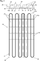
- Fig. 2 shows an acoustic ceiling 26 with a reinforcement 30 in the form of a cross reinforcement, lattice girders 34, an air conditioning device 31 and a large number of acoustic bodies 1.
- a reinforcement 30 in the form of a cross reinforcement
- lattice girders 34 lattice girders 34
- an air conditioning device 31 a large number of acoustic bodies 1.
- the acoustic bodies 1 are shown in the side view located above and not shown in the plan view located below.
- the acoustic ceiling 26 comprises a first top surface 27, a second top surface 28 spaced therefrom, and acoustic bodies 1 made of plastic 24 arranged between the two top surfaces 27, 28 arranged sound-conducting recesses 29 is connected to the first top surface 27.
- the acoustic bodies 1 are formed separately from the acoustic ceiling 26 and the acoustic bodies 1 each enclose two recesses 29.
- a number of recesses 29 enclosed by the acoustic body 1 is generally any.
- the acoustic body 1 can, for example, also enclose exactly four cutouts 29.
- the reinforcement 30 comprises transverse struts 32a and longitudinal struts 32b, the recesses 29 being arranged between the transverse struts 31 and longitudinal struts 32.
- the air conditioning device 31 comprises pipe sections 33, the recesses 29 being arranged between the pipe sections 33.
- the lattice girders 34 comprise lower chords 35 and upper chords 36, the acoustic bodies 1 being arranged between the upper chords 36 and the lower chords 35 of separate lattice girders 34.
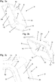
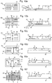
- Fig. 3a shows a first acoustic element 2, stacking devices 14 in the form of a vertical strut being arranged on inner side surfaces 10 of the first acoustic element 2, via which a plurality of first acoustic elements 2 can be stacked.
- the first acoustic element 2 has a rectangular cross-sectional shape 20.
- Figure 3c shows an enlarged detail from Figure 3b It can be seen that a region of the outer side surfaces 9 of the first acoustic element 2 can be inserted in concrete via the spacer device 17 and a second acoustic element 3 can be connected to the first acoustic element 2 via receiving means 13 of the first acoustic element 2.
- Figure 4a shows a second acoustic element 3, the second acoustic element 3 having indentations 15, with an underside 16 of the indentations 15 a first acoustic element 2 can be arranged when the two acoustic elements 2, 3 are connected via the connecting device 4.
- a bulge 22 in the form of a stiffening strut is arranged on a top surface 7.
- pipe connections 23 are arranged in the form of a predetermined breaking point, at which line connections 44 can be arranged by breaking out the predetermined breaking points on the second acoustic element 3.
- Figure 4b shows the second acoustic element 3 from an underside in a perspective view, with stacking devices 14 in the form of a vertical strut being arranged on the inner side surfaces 10 of the second acoustic element 3, via which a plurality of second acoustic elements 3 can be stacked.
- Figure 4c shows an enlarged detail from Figure 4b It can be seen that a connection to a first acoustic element 2 can be established via latching devices 12.
- Fig. 5 shows two second acoustic elements 3 stacked on top of each other in a side view located above in a sectional view in the direction of the arrow of the top view of the second acoustic element 3 located below essentially no negative pressure between the two second acoustic elements 3 when the stacking is dissolved.
- Fig. 6 shows the second acoustic element with a rectangular cross-sectional shape 20 in a plan view located on the left and a sectional view located on the right in the direction of the arrow.
- the inner side surfaces 10 of the second acoustic element 3 enclose an angle 18 of essentially 18 °.
- the outer side surfaces 9 of the first acoustic element 2 generally have an identical angle 18 as the inner side surfaces 19 of the second acoustic element 3.
- a latching device 12 in the form of a nub can be seen, which is firmly connected to the inner side surface 19 of the second acoustic element 3.
- the latching device 12 can also be applied to the inner side surface 19 in some other way.
- Figure 7a shows a second acoustic element 3 in a higher embodiment than Figure 4a .
- Both embodiments of the second acoustic element 3 can with the first acoustic element 2 according to Fig. 3a be connected to form an acoustic body 1.
- Figure 7b differs from Figure 7a only to the effect that the second acoustic element is shown in a plan view.
- the bulge 22 is formed in a cross shape for reasons of strength.
- the indentations 15 are arranged below the indentation 22 and extend as far as the top surface 7.
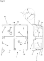
- Fig. 8 shows an acoustic body 1 for ceiling elements 26a to reduce the reverberation time of sound, the acoustic body 1 having a first acoustic element 2 and a second acoustic element 3, a connecting device 4 being provided with which the two acoustic elements 2, 3 can be detachably connected to one another.
- the side view can be seen in a sectional view in the direction of the arrow.
- the first acoustic element 2 has a sound inlet opening 5 and a sound outlet opening 6 spaced therefrom.
- the second acoustic element 3 has a sound inlet opening 5 and a cover surface 7 spaced therefrom.
- the two acoustic elements 2, 3 are connected to one another by means of the connecting device 4 in such a way that the sound outlet opening 6 of the first acoustic element 2 overlaps 8 with the sound inlet opening 5 of the second acoustic element 3. Sound is conducted from the first acoustic element 2 into the second acoustic element 3 up to the top surface 7.
- the two acoustic elements 2, 3 have outer side surfaces 9 and inner side surfaces 10, the second acoustic element 3 with the inner side surfaces 10 of the second acoustic element 3 being slipped over the outer side surfaces 9 of the first acoustic element 2 with a lateral clearance 11 of essentially 0.2 mm.
- first acoustic element 2 with the inner side surfaces 10 of the first acoustic element 2 can also be slipped over the outer side surfaces 9 of the second acoustic element 3 or slipped over it without play.
- the first acoustic element 2 and the second acoustic element 3 are made entirely of plastic 24.
- the two acoustic elements 2, 3 are made by injection molding. In general, the two acoustic elements 2, 3 can also be produced by 3D printing or vacuum drawing.
- the second acoustic element 3 has locking devices 12 in the form of a knob on the inner side surfaces 10 and the first acoustic element 2 has receiving means 13 corresponding to the locking devices 12 on the outer side surfaces 9 in the form of a groove into which the locking devices 12 are locked.
- the first acoustic element 2 is connected to the second acoustic element 3 in a form-fitting and force-fitting manner.
- a side length 21 of the first acoustic element 2 is essentially 350 mm.
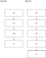
- Figures 10a-10f Explicit in the side views, which are located schematically on the right, a method for producing an acoustic ceiling 26, a schematic plan view located on the left being shown to illustrate the method steps.
- Figure 10a shows that the recess bodies 37 are arranged on the concreting platform 38 by a robot 41 via two magnets 40.
- the recess bodies 37 have positioning means 19 in the form of a metal plate.
- a lighting element 42 and a ventilation device 43 are arranged on the concreting platform 38 instead of a recess body 37.
- Figure 10b shows that the lattice girder 34 and a reinforcement 30 are arranged next to the recess bodies 37.
- Figure 10c shows that concrete 39 encloses the recess body 37 and the ventilation device 43 in areas and the lighting element 42 at least in areas.
- Fig. 10d shows that first acoustic elements 2 are inserted in some areas into the not yet hardened concrete 39 (can be seen on the right). The concrete 39 is then hardened. In this state, the ceiling element 26a can be transported to the construction site, for example, with the recess bodies being removed. The recess bodies 1 are generally removed before the second acoustic elements 3 are enclosed with concrete 39 in order to form the sound-conducting recesses 29.
- a line connection 44 in the form of piping is arranged on the ventilation device 43 and Insulating elements 25 inserted into the first acoustic elements 2 (visible on the left).
- the recess bodies 37 have already been removed, sound-conducting recesses 29 and the ventilation device 43 being visible in a plan view.
- the lighting device 42 has also been indicated; however, the lighting device 42 can generally be covered with concrete 39 at least in some areas.
- another line connection 44 such as a power connection to the lighting device 42 can also be arranged.
- the insulating element 25 in the form of fleece is arranged within the acoustic body 1 completely within the inner side surfaces 10 of the first acoustic element 2.
- the insulating element 25 has a heat-insulating effect and can reinforce a reduction in sound.
- a cover body 45 in the form of plastic has already been arranged in a sound-conducting recess 29.
- coarse-grain acoustic paint and / or open-pored outer cladding can also be arranged in a region around the at least one sound-conducting recess 29 in a subsequent process step.
- Figure 10e shows that second acoustic elements 3 are slipped onto the first acoustic elements 2, a connection being established between the two acoustic elements 2, 3 via a connecting device 4 to form the acoustic body 1.
- Positioning means 19 in the form of a metal plate are on the second acoustic elements 3 for positioning the second acoustic elements 3 arranged.
- the first acoustic elements 2 can also have positioning means 19 - for example in the form of a magnet 30 or a tool holder.
- line connections 44 in the form of a power connection, a pipe connection and a ventilation connection are arranged between two second acoustic elements 3 and between an acoustic body 1 and the ventilation device 43.
- a ceiling box can be integrated via the line connection 44.
- Fig. 10f shows that before enclosing the second acoustic elements 3 with concrete 39, a further reinforcement 30 is arranged on the acoustic bodies 1 and the reinforcement 30 together with the acoustic bodies 1 is enclosed with concrete 39 to form the acoustic ceiling 26, the not yet hardened concrete being shaken and is cured.
Landscapes
- Engineering & Computer Science (AREA)
- Architecture (AREA)
- Physics & Mathematics (AREA)
- Electromagnetism (AREA)
- Civil Engineering (AREA)
- Structural Engineering (AREA)
- Acoustics & Sound (AREA)
- Building Environments (AREA)
Applications Claiming Priority (1)
| Application Number | Priority Date | Filing Date | Title |
|---|---|---|---|
| ATA50377/2020A AT522885B1 (de) | 2020-05-04 | 2020-05-04 | Akustikkörper, insbesondere für Deckenelemente, zur Reduktion einer Nachhallzeit von Schall |
Publications (3)
| Publication Number | Publication Date |
|---|---|
| EP3907341A1 true EP3907341A1 (fr) | 2021-11-10 |
| EP3907341C0 EP3907341C0 (fr) | 2023-11-22 |
| EP3907341B1 EP3907341B1 (fr) | 2023-11-22 |
Family
ID=74859606
Family Applications (1)
| Application Number | Title | Priority Date | Filing Date |
|---|---|---|---|
| EP21167192.0A Active EP3907341B1 (fr) | 2020-05-04 | 2021-04-07 | Corps acoustique pour éléments de plafond permettant de réduire le temps de réverbération du son |
Country Status (4)
| Country | Link |
|---|---|
| EP (1) | EP3907341B1 (fr) |
| AT (1) | AT522885B1 (fr) |
| HU (1) | HUE065404T2 (fr) |
| PL (1) | PL3907341T3 (fr) |
Cited By (1)
| Publication number | Priority date | Publication date | Assignee | Title |
|---|---|---|---|---|
| EP4223951A1 (fr) * | 2022-02-03 | 2023-08-09 | Saqib Hashim Aziz | Système multifonctionel et procédé de réalisation d'éléments structuraux, ainsi que leur procédé d'optimisation |
Citations (4)
| Publication number | Priority date | Publication date | Assignee | Title |
|---|---|---|---|---|
| US3442058A (en) * | 1968-05-31 | 1969-05-06 | Eng Collaborative Ltd The | Concrete floor construction with duct-forming voids |
| FR2395366A1 (fr) * | 1977-06-22 | 1979-01-19 | Babu Jean Pierre | Element prefabrique double de coffrage et parement pour la construction de dalles de plafond en beton |
| WO2011098156A1 (fr) | 2010-02-13 | 2011-08-18 | Klimatop Gmbh | Module de construction à composant acoustique incorporé |
| EP2589719A1 (fr) * | 2010-06-28 | 2013-05-08 | Alberto Alarcon Garcia | Coffrage ou élément de structure similaire allégé dans lequel peuvent passer des conduits repérables |
Family Cites Families (6)
| Publication number | Priority date | Publication date | Assignee | Title |
|---|---|---|---|---|
| JP2004100383A (ja) * | 2002-09-12 | 2004-04-02 | Yoshida Komuten:Kk | 型枠合板残材を有効利用したボイドスラブの構築方法 |
| BE1015117A5 (nl) * | 2002-09-23 | 2004-10-05 | Belvi Nv | Prefabelement en werkwijze voor het vervaardigen ervan. |
| IT201600083287A1 (it) * | 2016-08-08 | 2018-02-08 | T P S S R L | Elemento di alleggerimento per l'edilizia. |
| DE102016118298B8 (de) * | 2016-09-28 | 2018-01-18 | Heinze Gruppe Verwaltungs Gmbh | Betondecke, Bausatz zur Herstellung einer Betondecke und Verfahren zur Herstellung einer Betondecke |
| CN107268990A (zh) * | 2017-06-27 | 2017-10-20 | 徐焱 | 一种加底盖的塑料模壳 |
| AU2019101738B4 (en) * | 2018-07-02 | 2021-02-11 | Neumann Steel Pty Ltd | A void forming module and system therefor |
-
2020
- 2020-05-04 AT ATA50377/2020A patent/AT522885B1/de active
-
2021
- 2021-04-07 HU HUE21167192A patent/HUE065404T2/hu unknown
- 2021-04-07 EP EP21167192.0A patent/EP3907341B1/fr active Active
- 2021-04-07 PL PL21167192.0T patent/PL3907341T3/pl unknown
Patent Citations (4)
| Publication number | Priority date | Publication date | Assignee | Title |
|---|---|---|---|---|
| US3442058A (en) * | 1968-05-31 | 1969-05-06 | Eng Collaborative Ltd The | Concrete floor construction with duct-forming voids |
| FR2395366A1 (fr) * | 1977-06-22 | 1979-01-19 | Babu Jean Pierre | Element prefabrique double de coffrage et parement pour la construction de dalles de plafond en beton |
| WO2011098156A1 (fr) | 2010-02-13 | 2011-08-18 | Klimatop Gmbh | Module de construction à composant acoustique incorporé |
| EP2589719A1 (fr) * | 2010-06-28 | 2013-05-08 | Alberto Alarcon Garcia | Coffrage ou élément de structure similaire allégé dans lequel peuvent passer des conduits repérables |
Cited By (1)
| Publication number | Priority date | Publication date | Assignee | Title |
|---|---|---|---|---|
| EP4223951A1 (fr) * | 2022-02-03 | 2023-08-09 | Saqib Hashim Aziz | Système multifonctionel et procédé de réalisation d'éléments structuraux, ainsi que leur procédé d'optimisation |
Also Published As
| Publication number | Publication date |
|---|---|
| AT522885A4 (de) | 2021-03-15 |
| HUE065404T2 (hu) | 2024-05-28 |
| AT522885B1 (de) | 2021-03-15 |
| EP3907341C0 (fr) | 2023-11-22 |
| EP3907341B1 (fr) | 2023-11-22 |
| PL3907341T3 (pl) | 2024-04-22 |
Similar Documents
| Publication | Publication Date | Title |
|---|---|---|
| DE69433730T2 (de) | Befestigung einer Wandverkleidung | |
| EP1038073B1 (fr) | Delimitation spatiale constituee d'elements prefabriques, telle que parois exterieures, cloisons et plafonds ou similaire, et leur procede d'installation | |
| EP2925938B1 (fr) | Élément de revêtement pour un bâtiment | |
| WO1996036777A1 (fr) | Element de paroi finie a conduits integres | |
| AT522885B1 (de) | Akustikkörper, insbesondere für Deckenelemente, zur Reduktion einer Nachhallzeit von Schall | |
| EP4223951A1 (fr) | Système multifonctionel et procédé de réalisation d'éléments structuraux, ainsi que leur procédé d'optimisation | |
| EP1892350A2 (fr) | Panneau préfabriqué pour la réalisation d'un mur à double couche d'un bâtiment | |
| DE69205965T2 (de) | Verfahren zur Herstellung eines Deckenelementes oder einer Rippedecken und Wärmedämmplatte für Deckenelementen. | |
| DE2500256A1 (de) | Mauerwerk und verfahren zu seiner herstellung | |
| EP1187281A2 (fr) | Canalisation antifeu pour câble et méthode de fabrication | |
| DE102020113406A1 (de) | Raummodul | |
| DE19637379A1 (de) | Verfahren und Vorrichtung zum Herstellen von Bauelementen sowie danach hergestellte Bauelemente | |
| EP3315682B1 (fr) | Élément de coffrage et procédé de fabrication d'un plafond de bâtiment | |
| DE29922263U1 (de) | Aussparungskörper für Betondecken | |
| DE102011114684B4 (de) | Rohrträger für ein Flächentemperiersystem in Betonböden, -wänden und -decken | |
| DE202021101571U1 (de) | Einsatzmodul für ein Wandelement und Wandelement mit Einsatzmodul | |
| DE2322920C3 (de) | Fertigbauteil für die Herstellung von Gebäuden | |
| DE102007030339A1 (de) | Gebäudebauelement und Verfahren zum Herstellen | |
| EP1662059B1 (fr) | Panneau de plancher pour un système de plancher creux, procédé de production d'un panneau de plancher et un sytème de plancher creux avec un panneau de plancher | |
| EP1094169B1 (fr) | Elément préfabriqué pour des maisons préfabriquées | |
| DE20112669U1 (de) | Schallabsorbierendes Paneel | |
| DE202010004816U1 (de) | Vorrichtung zum Herstellen eines Skelettbausegments, ein Skelettbausegment, das mittels dieser Vorrichtung hergestellt wurde und ein Gebäude, das dieses Skelettbausegment umfasst | |
| DE102022209734A1 (de) | Verfahren zur Herstellung einer Raumzelle und eines Raumzellenteils | |
| EP0634130B1 (fr) | Support pour bac de douche | |
| DE856350C (de) | Tragendes Bauelement, insbesondere fuer Zwischenwaende |
Legal Events
| Date | Code | Title | Description |
|---|---|---|---|
| PUAI | Public reference made under article 153(3) epc to a published international application that has entered the european phase |
Free format text: ORIGINAL CODE: 0009012 |
|
| STAA | Information on the status of an ep patent application or granted ep patent |
Free format text: STATUS: THE APPLICATION HAS BEEN PUBLISHED |
|
| AK | Designated contracting states |
Kind code of ref document: A1 Designated state(s): AL AT BE BG CH CY CZ DE DK EE ES FI FR GB GR HR HU IE IS IT LI LT LU LV MC MK MT NL NO PL PT RO RS SE SI SK SM TR |
|
| B565 | Issuance of search results under rule 164(2) epc |
Effective date: 20210914 |
|
| STAA | Information on the status of an ep patent application or granted ep patent |
Free format text: STATUS: REQUEST FOR EXAMINATION WAS MADE |
|
| 17P | Request for examination filed |
Effective date: 20220421 |
|
| RBV | Designated contracting states (corrected) |
Designated state(s): AL AT BE BG CH CY CZ DE DK EE ES FI FR GB GR HR HU IE IS IT LI LT LU LV MC MK MT NL NO PL PT RO RS SE SI SK SM TR |
|
| STAA | Information on the status of an ep patent application or granted ep patent |
Free format text: STATUS: EXAMINATION IS IN PROGRESS |
|
| 17Q | First examination report despatched |
Effective date: 20230313 |
|
| P01 | Opt-out of the competence of the unified patent court (upc) registered |
Effective date: 20230512 |
|
| GRAP | Despatch of communication of intention to grant a patent |
Free format text: ORIGINAL CODE: EPIDOSNIGR1 |
|
| STAA | Information on the status of an ep patent application or granted ep patent |
Free format text: STATUS: GRANT OF PATENT IS INTENDED |
|
| INTG | Intention to grant announced |
Effective date: 20230712 |
|
| GRAS | Grant fee paid |
Free format text: ORIGINAL CODE: EPIDOSNIGR3 |
|
| GRAA | (expected) grant |
Free format text: ORIGINAL CODE: 0009210 |
|
| STAA | Information on the status of an ep patent application or granted ep patent |
Free format text: STATUS: THE PATENT HAS BEEN GRANTED |
|
| AK | Designated contracting states |
Kind code of ref document: B1 Designated state(s): AL AT BE BG CH CY CZ DE DK EE ES FI FR GB GR HR HU IE IS IT LI LT LU LV MC MK MT NL NO PL PT RO RS SE SI SK SM TR |
|
| RAP3 | Party data changed (applicant data changed or rights of an application transferred) |
Owner name: GREEN CODE GMBH |
|
| REG | Reference to a national code |
Ref country code: GB Ref legal event code: FG4D Free format text: NOT ENGLISH |
|
| REG | Reference to a national code |
Ref country code: CH Ref legal event code: EP |
|
| REG | Reference to a national code |
Ref country code: DE Ref legal event code: R096 Ref document number: 502021001997 Country of ref document: DE |
|
| REG | Reference to a national code |
Ref country code: IE Ref legal event code: FG4D Free format text: LANGUAGE OF EP DOCUMENT: GERMAN |
|
| U01 | Request for unitary effect filed |
Effective date: 20231219 |
|
| U07 | Unitary effect registered |
Designated state(s): AT BE BG DE DK EE FI FR IT LT LU LV MT NL PT SE SI Effective date: 20240103 |
|
| P04 | Withdrawal of opt-out of the competence of the unified patent court (upc) registered |
Effective date: 20231222 |
|
| PG25 | Lapsed in a contracting state [announced via postgrant information from national office to epo] |
Ref country code: GR Free format text: LAPSE BECAUSE OF FAILURE TO SUBMIT A TRANSLATION OF THE DESCRIPTION OR TO PAY THE FEE WITHIN THE PRESCRIBED TIME-LIMIT Effective date: 20240223 |
|
| PG25 | Lapsed in a contracting state [announced via postgrant information from national office to epo] |
Ref country code: IS Free format text: LAPSE BECAUSE OF FAILURE TO SUBMIT A TRANSLATION OF THE DESCRIPTION OR TO PAY THE FEE WITHIN THE PRESCRIBED TIME-LIMIT Effective date: 20240322 |
|
| PG25 | Lapsed in a contracting state [announced via postgrant information from national office to epo] |
Ref country code: ES Free format text: LAPSE BECAUSE OF FAILURE TO SUBMIT A TRANSLATION OF THE DESCRIPTION OR TO PAY THE FEE WITHIN THE PRESCRIBED TIME-LIMIT Effective date: 20231122 |
|
| PG25 | Lapsed in a contracting state [announced via postgrant information from national office to epo] |
Ref country code: IS Free format text: LAPSE BECAUSE OF FAILURE TO SUBMIT A TRANSLATION OF THE DESCRIPTION OR TO PAY THE FEE WITHIN THE PRESCRIBED TIME-LIMIT Effective date: 20240322 Ref country code: GR Free format text: LAPSE BECAUSE OF FAILURE TO SUBMIT A TRANSLATION OF THE DESCRIPTION OR TO PAY THE FEE WITHIN THE PRESCRIBED TIME-LIMIT Effective date: 20240223 Ref country code: ES Free format text: LAPSE BECAUSE OF FAILURE TO SUBMIT A TRANSLATION OF THE DESCRIPTION OR TO PAY THE FEE WITHIN THE PRESCRIBED TIME-LIMIT Effective date: 20231122 |
|
| REG | Reference to a national code |
Ref country code: HU Ref legal event code: AG4A Ref document number: E065404 Country of ref document: HU |
|
| U20 | Renewal fee for the european patent with unitary effect paid |
Year of fee payment: 4 Effective date: 20240423 |
|
| PG25 | Lapsed in a contracting state [announced via postgrant information from national office to epo] |
Ref country code: RS Free format text: LAPSE BECAUSE OF FAILURE TO SUBMIT A TRANSLATION OF THE DESCRIPTION OR TO PAY THE FEE WITHIN THE PRESCRIBED TIME-LIMIT Effective date: 20231122 Ref country code: NO Free format text: LAPSE BECAUSE OF FAILURE TO SUBMIT A TRANSLATION OF THE DESCRIPTION OR TO PAY THE FEE WITHIN THE PRESCRIBED TIME-LIMIT Effective date: 20240222 Ref country code: HR Free format text: LAPSE BECAUSE OF FAILURE TO SUBMIT A TRANSLATION OF THE DESCRIPTION OR TO PAY THE FEE WITHIN THE PRESCRIBED TIME-LIMIT Effective date: 20231122 |
|
| PG25 | Lapsed in a contracting state [announced via postgrant information from national office to epo] |
Ref country code: CZ Free format text: LAPSE BECAUSE OF FAILURE TO SUBMIT A TRANSLATION OF THE DESCRIPTION OR TO PAY THE FEE WITHIN THE PRESCRIBED TIME-LIMIT Effective date: 20231122 |
|
| PG25 | Lapsed in a contracting state [announced via postgrant information from national office to epo] |
Ref country code: SK Free format text: LAPSE BECAUSE OF FAILURE TO SUBMIT A TRANSLATION OF THE DESCRIPTION OR TO PAY THE FEE WITHIN THE PRESCRIBED TIME-LIMIT Effective date: 20231122 |
|
| PG25 | Lapsed in a contracting state [announced via postgrant information from national office to epo] |
Ref country code: SM Free format text: LAPSE BECAUSE OF FAILURE TO SUBMIT A TRANSLATION OF THE DESCRIPTION OR TO PAY THE FEE WITHIN THE PRESCRIBED TIME-LIMIT Effective date: 20231122 Ref country code: SK Free format text: LAPSE BECAUSE OF FAILURE TO SUBMIT A TRANSLATION OF THE DESCRIPTION OR TO PAY THE FEE WITHIN THE PRESCRIBED TIME-LIMIT Effective date: 20231122 Ref country code: RO Free format text: LAPSE BECAUSE OF FAILURE TO SUBMIT A TRANSLATION OF THE DESCRIPTION OR TO PAY THE FEE WITHIN THE PRESCRIBED TIME-LIMIT Effective date: 20231122 Ref country code: CZ Free format text: LAPSE BECAUSE OF FAILURE TO SUBMIT A TRANSLATION OF THE DESCRIPTION OR TO PAY THE FEE WITHIN THE PRESCRIBED TIME-LIMIT Effective date: 20231122 |
|
| REG | Reference to a national code |
Ref country code: DE Ref legal event code: R097 Ref document number: 502021001997 Country of ref document: DE |
|
| PLBE | No opposition filed within time limit |
Free format text: ORIGINAL CODE: 0009261 |
|
| STAA | Information on the status of an ep patent application or granted ep patent |
Free format text: STATUS: NO OPPOSITION FILED WITHIN TIME LIMIT |
|
| 26N | No opposition filed |
Effective date: 20240823 |
|
| PG25 | Lapsed in a contracting state [announced via postgrant information from national office to epo] |
Ref country code: MC Free format text: LAPSE BECAUSE OF FAILURE TO SUBMIT A TRANSLATION OF THE DESCRIPTION OR TO PAY THE FEE WITHIN THE PRESCRIBED TIME-LIMIT Effective date: 20231122 |
|
| PG25 | Lapsed in a contracting state [announced via postgrant information from national office to epo] |
Ref country code: MC Free format text: LAPSE BECAUSE OF FAILURE TO SUBMIT A TRANSLATION OF THE DESCRIPTION OR TO PAY THE FEE WITHIN THE PRESCRIBED TIME-LIMIT Effective date: 20231122 |
|
| REG | Reference to a national code |
Ref country code: CH Ref legal event code: PL |
|
| P05 | Withdrawal of opt-out of the competence of the unified patent court (upc) changed |
Free format text: CASE NUMBER: APP_597261/2023 Effective date: 20240103 |
|
| PG25 | Lapsed in a contracting state [announced via postgrant information from national office to epo] |
Ref country code: CH Free format text: LAPSE BECAUSE OF NON-PAYMENT OF DUE FEES Effective date: 20240430 |
|
| PG25 | Lapsed in a contracting state [announced via postgrant information from national office to epo] |
Ref country code: IE Free format text: LAPSE BECAUSE OF NON-PAYMENT OF DUE FEES Effective date: 20240407 |
|
| PGFP | Annual fee paid to national office [announced via postgrant information from national office to epo] |
Ref country code: PL Payment date: 20250310 Year of fee payment: 5 |
|
| U20 | Renewal fee for the european patent with unitary effect paid |
Year of fee payment: 5 Effective date: 20250428 |
|
| PGFP | Annual fee paid to national office [announced via postgrant information from national office to epo] |
Ref country code: HU Payment date: 20250320 Year of fee payment: 5 |
|
| PG25 | Lapsed in a contracting state [announced via postgrant information from national office to epo] |
Ref country code: CY Free format text: LAPSE BECAUSE OF FAILURE TO SUBMIT A TRANSLATION OF THE DESCRIPTION OR TO PAY THE FEE WITHIN THE PRESCRIBED TIME-LIMIT; INVALID AB INITIO Effective date: 20210407 |
|
| GBPC | Gb: european patent ceased through non-payment of renewal fee |
Effective date: 20250407 |
|
| PG25 | Lapsed in a contracting state [announced via postgrant information from national office to epo] |
Ref country code: GB Free format text: LAPSE BECAUSE OF NON-PAYMENT OF DUE FEES Effective date: 20250407 |