EP3907342A1 - Élément de renfort et système de renfort pour l'absorption des forces dans des panneaux en béton - Google Patents
Élément de renfort et système de renfort pour l'absorption des forces dans des panneaux en béton Download PDFInfo
- Publication number
- EP3907342A1 EP3907342A1 EP20173598.2A EP20173598A EP3907342A1 EP 3907342 A1 EP3907342 A1 EP 3907342A1 EP 20173598 A EP20173598 A EP 20173598A EP 3907342 A1 EP3907342 A1 EP 3907342A1
- Authority
- EP
- European Patent Office
- Prior art keywords
- reinforcement
- elements
- carrier element
- carrier
- rod
- Prior art date
- Legal status (The legal status is an assumption and is not a legal conclusion. Google has not performed a legal analysis and makes no representation as to the accuracy of the status listed.)
- Pending
Links
Images

Classifications
-
- E—FIXED CONSTRUCTIONS
- E04—BUILDING
- E04C—STRUCTURAL ELEMENTS; BUILDING MATERIALS
- E04C5/00—Reinforcing elements, e.g. for concrete; Auxiliary elements therefor
- E04C5/01—Reinforcing elements of metal, e.g. with non-structural coatings
- E04C5/06—Reinforcing elements of metal, e.g. with non-structural coatings of high bending resistance, i.e. of essentially three-dimensional [3D] extent, e.g. lattice girders
- E04C5/0645—Shear reinforcements, e.g. shearheads for floor slabs
-
- E—FIXED CONSTRUCTIONS
- E04—BUILDING
- E04B—GENERAL BUILDING CONSTRUCTIONS; WALLS, e.g. PARTITIONS; ROOFS; FLOORS; CEILINGS; INSULATION OR OTHER PROTECTION OF BUILDINGS
- E04B5/00—Floors; Floor construction with regard to insulation; Connections specially adapted therefor
- E04B5/16—Load-carrying floor structures wholly or partly cast or similarly formed in situ
- E04B5/17—Floor structures partly formed in situ
- E04B5/23—Floor structures partly formed in situ with stiffening ribs or other beam-like formations wholly or partly prefabricated
- E04B5/29—Floor structures partly formed in situ with stiffening ribs or other beam-like formations wholly or partly prefabricated the prefabricated parts of the beams consisting wholly of metal
-
- E—FIXED CONSTRUCTIONS
- E04—BUILDING
- E04B—GENERAL BUILDING CONSTRUCTIONS; WALLS, e.g. PARTITIONS; ROOFS; FLOORS; CEILINGS; INSULATION OR OTHER PROTECTION OF BUILDINGS
- E04B5/00—Floors; Floor construction with regard to insulation; Connections specially adapted therefor
- E04B5/43—Floor structures of extraordinary design; Features relating to the elastic stability; Floor structures specially designed for resting on columns only, e.g. mushroom floors
Definitions
- the present invention relates to a reinforcement element for absorbing forces in concreted slabs, in particular in the area of support elements of concreted slabs, the reinforcement element being essentially formed from steel.
- the invention also relates to a reinforcement system for absorbing forces in concrete slabs, which system is formed from several reinforcement elements.
- Concrete ceilings and floor or foundation slabs which are supported by support elements, i.e. supports or bearing walls, must be designed in these areas in such a way that supporting forces can be optimally introduced into the concrete ceiling or foundation slab.
- support elements i.e. supports or bearing walls
- shear forces and punching shear forces occurring at the head of a slab prop are to be absorbed into the concrete slab in the support area, which is reinforced by inserting reinforcing steel.
- so-called steel mushrooms are used.
- This mushroom-like steel construction can be used in the form of a cross, the ends of the four legs being connected by means of one or more edge supports and thus forming the shape of a ring or a rectangle. Due to the larger contact or support surface of an inserted steel mushroom, the punching shear resistance in the area of the support element is increased.
- the integration of such compact steel mushrooms into a reinforcing steel structure proves to be problematic, in particular with regard to the implementation of bending reinforcement and due to the low design flexibility of the steel mushroom in relation to the local conditions.
- double-headed dowel strips are also known in the area of floor or ceiling panels that are at risk of being punched through. These double-headed dowel strips are arranged in a star shape around the support element, this arrangement leading to spatial problems with orthogonally laid reinforcement or making it more difficult to insert the reinforcement.
- stirrup cages which are formed from a plurality of right-angled or U-shaped push stirrups, which are connected to one another by means of straight bars extending transversely to their longitudinal direction.
- the stirrup cage also referred to as a push cage, can be placed on a lowermost reinforcement layer in the area of the support element. It is designed in such a way that it extends from the lower reinforcement layer into an upper reinforcement layer. An inner layer of the upper reinforcement can be inserted into the ends of the push handle bent in the shape of a hook and aligned with one another.
- push baskets are extremely material and labor intensive to manufacture and their load is limited.
- a reinforcement element in which at least one stirrup-shaped stirrup rod is welded with its end regions at a connection point on a base rod.
- the stirrup bar comprises an inclined area each, which form an angle with the base bar and a central area connecting the inclined areas, which is arranged above the support element and whose width corresponds approximately to the width of the support element.
- two such reinforcement elements are used crosswise, which are designed to be inserted into one another.
- a support head reinforcement in which opposing support elements are connected by a transmission member.
- the transmission member has a flat bow shape with end regions which are inclined towards a lower delimiting plane and on which anchor elements are provided.
- Each support element is formed by a horizontal plate and a web extending vertically upward therefrom and accordingly shows an inverse T shape. To connect to the transmission link, the respective webs can penetrate it.
- Several such elements can be arranged in a cross or star shape in the area of a support element.
- this type of support head reinforcement is complex and therefore associated with high costs in terms of production. Furthermore, the compressive forces that arise on the underside of the elements have to be taken over by the concrete, which limits the performance of the element.
- the object of the present invention is to create a reinforcement element for absorbing forces in areas of concrete slabs subject to shear forces, in particular in the area of support elements, which can absorb large loads and which can be produced simply and inexpensively.
- this object is achieved in that a first carrier element and a second carrier element arranged at a distance from it are connected by at least one rod-shaped connecting element, which rod-shaped connecting element has a first end region and a second end region for connection to the first carrier element and the second carrier element, respectively .
- the reinforcement element accordingly forms an elongated component, comprising a limited number of standard elements, which can be combined with one another with a certain variance.
- a reinforcement element that can be produced very easily and inexpensively is obtained, which can introduce the supporting forces in an optimal manner into the concrete ceiling or into the foundation slab.
- standard elements such as profile girders and reinforcing steel, for example made of ribbed steel, are used for the carrier elements and the at least one rod-shaped connecting element.
- the distance to be selected between the first carrier element and the second carrier element corresponds approximately to the width of the support element.
- the width is chosen in such a way that that the carrier elements still rest on an edge region of the support element.
- This construction of the reinforcement element defines an area between the carrier elements which essentially corresponds to the cross section of the support element.
- a construction of the support element, for example by casting, is only insignificantly affected by a positioned reinforcement element.
- the vertically extending reinforcement rods used in a support element designed as a concrete column can extend largely unimpaired through the free area between the carrier elements of the reinforcement element.
- At least one of the carrier elements of the reinforcement element is formed by a horizontal plate, also referred to as a flange, and a vertical web or middle part extending therefrom.
- the carrier element can have the shape of a T-profile, with a transverse part or flange and a central part or web.
- the carrier element (s) designed in this way with a flange arranged at the bottom are preferably provided in the reinforcement element.
- At least one of the carrier elements is designed in the form of an I-profile, with transverse parts or flanges, which can also be designed differently, being arranged on a web at the top and bottom.
- an I-profile can have parallel or at least one inclined inner surface of the flanges, depending on the design.
- Other cross-sectional shapes or profile shapes of the carrier elements are also conceivable for use in the reinforcement element according to the invention, which furthermore can also be different.
- Suitable profiles can be rolled or assembled by means of welding, screwing or riveting, and also be designed as hollow profiles.
- the at least one rod-shaped connecting element can be a rod or a bracket.
- An advantageous embodiment of the invention consists in that the first end region of the at least one rod-shaped connecting element is in an upper region of the first carrier element and the second end region of the rod-shaped connecting element in an upper region of the second carrier element are connected to the latter by welding.
- the lengths of the rod-shaped connecting element and the end regions via which the rod-shaped connecting element can be connected to the carrier elements can vary depending on the spatial conditions of the use of the reinforcement element.
- the end regions of the rod-shaped connecting element are connected to an outer surface or, in a further embodiment, to an inner surface of the flanges of the first carrier element and the second carrier element by welding.
- two straight bars parallel to one another are provided, which are each connected to the carrier elements in an upper region.
- these are welded to the outer surface or to the inner surface of the upper flange of the profile support element.
- the parallel straight bars can have a distance from one another, which can be selected so that any vertical bars of the support element that may be present can be guided unhindered.
- one of the two rod-shaped connecting elements with the upper flange and a further rod-shaped connecting element with the underside of the carrier elements, in particular with an inner surface or an outer surface of the lower flanges in the case of the I-profiles formed support elements are connected.
- the first and the second carrier element are connected in their upper area and their lower area by at least three rod-shaped connecting elements that are largely parallel to one another.
- a preferred embodiment comprises two upper rod-shaped connecting elements and at least one, preferably two, lower rod-shaped connecting elements.
- the carrier elements can in particular be designed as an inverted T-profile, as an I-profile and can be combined with one another in a variety of ways.
- the number and / or the arrangement of the rod-shaped connecting elements, as well as their shape, material and dimensions, can also be varied.
- the reinforcement elements are designed in such a way that a reinforcement system for absorbing forces in concrete ceilings or foundation slabs in the area of support elements can be assembled from several reinforcement elements.
- a reinforcement system for absorbing forces in concrete ceilings or foundation slabs in the area of support elements can be assembled from several reinforcement elements.
- several reinforcement elements can be used crosswise.
- reinforcement elements with two different heights are advantageously used, so that the reinforcement elements with a lower height can be pushed into the reinforcement elements with a greater height.
- these reinforcement elements can be put together in an optimal way for a wide variety of fields of application.
- reinforcement elements can be used in an advantageous manner, which are aligned parallel to each other and transversely to the longitudinal direction of the support element, whereby an optimal reinforcement system can be achieved, for example for supporting walls.
- the reinforcement element 1 consists of a first carrier element 10 and a second carrier element 12.
- the carrier elements 10, 12 are connected to one another via a vertical axis 2 by means of at least one rod-shaped connecting element 20.
- the first carrier element 10 and the second carrier element 12 are connected by a plurality of rod-shaped connecting elements 20 and 20 ′ on an upper side 24 and a lower side 22, respectively.
- Rod-shaped connecting elements 20, 20 ' can be designed as rods, but can also have a curved shape.
- Each of the rod-shaped connecting elements 20, 20 ' comprises a first end region 21 and a second end region 21 ', which are each connected to the first carrier element 10 and the second carrier element 12 by welding.
- additional reinforcing elements can also be used, which are not shown.
- the end Figure 1 it can be seen how the reinforcement element 1 can be used.
- a support element 30 is shown schematically, which is intended to support a concreted slab 40.
- the reinforcement element 1 is used in such a way that it comes to lie above the width of the support element 30.
- the reinforcement element 1 can come to rest with its underside 22 during installation, for example, on a first lower bending reinforcement layer of the plate 40.
- the upper side 24 of the reinforcement element 1 can come to lie at the level of an uppermost of several reinforcement layers of the plate 40.
- the reinforcement element 1 is thus optimally integrated into the reinforcement layers of the plate 40.
- the first carrier element 10 is spaced apart from the second carrier element 12 by a distance 26, the length of which is matched to a width of the support element 30, so that the carrier elements 10, 12 or the lower rod-shaped connection element (s) 20 'on an edge region of the support element 30 rest. In this way, a largely free volume is formed above the support element 30, which is suitable both for producing a support element and, in particular, for passing through any vertical support rods of the support element 30.
- Figure 2 shows a side view of the reinforcement element 1 according to the first embodiment, from which the cross-sectional profile of the carrier elements 10, 12 is visible.
- the first carrier element 10 and the second carrier element are each designed in the form of an I-profile.
- Such a profile comprises a middle part 51, an upper flange 50 and a lower flange 52.
- the upper flange 50 and the lower flange 52 each have outer surfaces 53 and 53 'and inner surfaces directed towards one another 54 or 54 '.
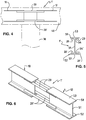
- the Figures 4 to 6 show a second embodiment of a reinforcement element 1, here designated 1 ', which is also formed from a first carrier element 10, a second carrier element 12 and rod-shaped connecting elements 20, 20'.
- the reinforcement element 1 ' is arranged in a region of the support element 30 which supports the plate 40 or a concrete ceiling.
- the second embodiment of the reinforcement element 1 ' differs from the first embodiment in that the rod-shaped connecting elements 20, 20' are each arranged on the inner surface 54 of the upper flange 50 and the inner surface 54 'of the lower flange 52, which are connected to the central part or Web 51 form the I-profile of the carrier elements 10, 12.
- a reinforcement element 1 ' is formed which, in contrast to the ones shown in FIGS Figures 1 to 3 illustrated embodiments of the reinforcement element 1 has a lower overall height.
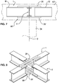
- the Figures 7 and 8 show an embodiment of a reinforcement system 60, which on the one hand consists of a first reinforcement element 1, according to the first embodiment of FIG Figures 1 to 3 and on the other hand from a second reinforcement element 1 ', according to the second embodiment of FIG Figures 4 to 6 , is composed.
- the first reinforcement element 1 is arranged crosswise to the second reinforcement element 1 '.
- the second reinforcement element 1 ' has a different arrangement of the rod-shaped connecting elements 20, 20' compared to the first reinforcing element 1, ie the rod-shaped connecting elements 20, 20 'are in the second reinforcing element 1' with the inner surfaces 54, 54 'of the upper flange 50 or . of the lower flange 52 is welded.
- the second reinforcement element 1 ′ accordingly has a lower height than the first reinforcement element 1 and can thus be pushed into the first reinforcement element 1.
- This reinforcement system 60 is used in the slab 40 or the concrete ceiling, as shown in FIG Figure 7 is shown.
- the reinforcement system 60 can be arranged between a lower and an upper reinforcement layer of the plate 40, more specifically to a second lower reinforcement layer and a third reinforcement layer, which forms the upper reinforcement layer with a fourth reinforcement layer. Accordingly, the reinforcement system 60 can be optimally integrated into the bending movement positions of the slab 40 or concrete ceiling.
Landscapes
- Engineering & Computer Science (AREA)
- Architecture (AREA)
- Civil Engineering (AREA)
- Structural Engineering (AREA)
- Physics & Mathematics (AREA)
- Electromagnetism (AREA)
- Reinforcement Elements For Buildings (AREA)
Priority Applications (1)
| Application Number | Priority Date | Filing Date | Title |
|---|---|---|---|
| EP20173598.2A EP3907342A1 (fr) | 2020-05-07 | 2020-05-07 | Élément de renfort et système de renfort pour l'absorption des forces dans des panneaux en béton |
Applications Claiming Priority (1)
| Application Number | Priority Date | Filing Date | Title |
|---|---|---|---|
| EP20173598.2A EP3907342A1 (fr) | 2020-05-07 | 2020-05-07 | Élément de renfort et système de renfort pour l'absorption des forces dans des panneaux en béton |
Publications (1)
| Publication Number | Publication Date |
|---|---|
| EP3907342A1 true EP3907342A1 (fr) | 2021-11-10 |
Family
ID=70617053
Family Applications (1)
| Application Number | Title | Priority Date | Filing Date |
|---|---|---|---|
| EP20173598.2A Pending EP3907342A1 (fr) | 2020-05-07 | 2020-05-07 | Élément de renfort et système de renfort pour l'absorption des forces dans des panneaux en béton |
Country Status (1)
| Country | Link |
|---|---|
| EP (1) | EP3907342A1 (fr) |
Citations (5)
| Publication number | Priority date | Publication date | Assignee | Title |
|---|---|---|---|---|
| US1461891A (en) * | 1922-02-11 | 1923-07-17 | Franklin H Coney | Concrete building |
| US4476662A (en) * | 1981-10-28 | 1984-10-16 | Fisher James M | Joist girder building construction |
| CH686686A5 (de) | 1993-03-26 | 1996-05-31 | Tobler Stahlbau Ag | Stuetzenkopfverstaerkung. |
| EP1932978A1 (fr) | 2006-12-14 | 2008-06-18 | Nivo AG | Elément d'armature pour l'absorption de forces dans des plaques de béton dans la zone d'éléments d'appui |
| US20180127966A1 (en) * | 2016-11-04 | 2018-05-10 | Kurosawa Construction Co., Ltd. | Method for jointing concrete column and iron beam |
-
2020
- 2020-05-07 EP EP20173598.2A patent/EP3907342A1/fr active Pending
Patent Citations (5)
| Publication number | Priority date | Publication date | Assignee | Title |
|---|---|---|---|---|
| US1461891A (en) * | 1922-02-11 | 1923-07-17 | Franklin H Coney | Concrete building |
| US4476662A (en) * | 1981-10-28 | 1984-10-16 | Fisher James M | Joist girder building construction |
| CH686686A5 (de) | 1993-03-26 | 1996-05-31 | Tobler Stahlbau Ag | Stuetzenkopfverstaerkung. |
| EP1932978A1 (fr) | 2006-12-14 | 2008-06-18 | Nivo AG | Elément d'armature pour l'absorption de forces dans des plaques de béton dans la zone d'éléments d'appui |
| US20180127966A1 (en) * | 2016-11-04 | 2018-05-10 | Kurosawa Construction Co., Ltd. | Method for jointing concrete column and iron beam |
Similar Documents
| Publication | Publication Date | Title |
|---|---|---|
| WO2004079127A1 (fr) | Dispositif pour fixer des plaques contre les murs exterieurs d'edifices | |
| DE19756358A1 (de) | Schubbewehrung für Flachdecken und Dübelleiste hierfür | |
| EP2281959B1 (fr) | Elément de connexion pour dalle en porte-à-faux | |
| WO1981000272A1 (fr) | Element de couverture prefabrique pour la couverture de toits | |
| DE602005004450T2 (de) | Bewehrte verlorene Schalung, insbesondere für kreuzförmig bewehrte Böden, und damit hergestellter Boden | |
| EP3907342A1 (fr) | Élément de renfort et système de renfort pour l'absorption des forces dans des panneaux en béton | |
| EP2166171B1 (fr) | Armature de poinçonnement d'une structure en béton armé contre le poinçonnement aux alentours de la zone d'appui d'une dalle | |
| EP1932978B1 (fr) | Elément d'armature pour l'absorption de forces dans des plaques de béton dans la zone d'éléments d'appui | |
| DE9401717U1 (de) | Stützenkopfverstärkung | |
| EP3617415B1 (fr) | Élément d'armature de poinçonnement et construction dotée d'une plaque dotée d'un élément d'armature de poinçonnement | |
| EP3346058A1 (fr) | Module de mur en gabions et procédé de fabrication d'un mur en gabions pourvu d'au moins un module de mur en gabions | |
| DE10350082B4 (de) | Vorgespannte Flachdecke mit Hohldeckenplatten | |
| EP4116516A1 (fr) | Insert de coffrage en béton | |
| DE102004040584A1 (de) | Bauelement zur Schubbewehrung | |
| EP0353560A1 (fr) | Espaceur pour armatures de béton | |
| DE29808491U1 (de) | Bewehrungselement für Schubbewehrungen | |
| AT411652B (de) | Verfahren zur herstellung einer schubarmierung in gestützten betondecken | |
| EP4050170B1 (fr) | Construction pourvue d'élément thermoisolant | |
| DE202008010535U1 (de) | Schalungselement | |
| WO2000005461A1 (fr) | Dalle en beton arme et element d'armature de cisaillement pour l'armature de cisaillement de dalles en beton arme | |
| EP2143851B1 (fr) | Elément d'armature pour l'absorption de forces dans les bords latéraux de plaques en béton aux alentours d'éléments d'appui | |
| EP4299861A1 (fr) | Dispositif et procédé de renforcement ultérieur d'un composant doté d'au moins une zone de discontinuité | |
| CH720665A2 (de) | Verstärkungselement für ein Durchstanz- und Schubbewehrungssystem für ein Betonbauelement | |
| DE102021117719A1 (de) | Betonformungseinlage | |
| EP4112833A1 (fr) | Agencement de renfort permettant d'augmenter la résistance au poinçonnage, ainsi que procédé associé |
Legal Events
| Date | Code | Title | Description |
|---|---|---|---|
| PUAI | Public reference made under article 153(3) epc to a published international application that has entered the european phase |
Free format text: ORIGINAL CODE: 0009012 |
|
| STAA | Information on the status of an ep patent application or granted ep patent |
Free format text: STATUS: THE APPLICATION HAS BEEN PUBLISHED |
|
| AK | Designated contracting states |
Kind code of ref document: A1 Designated state(s): AL AT BE BG CH CY CZ DE DK EE ES FI FR GB GR HR HU IE IS IT LI LT LU LV MC MK MT NL NO PL PT RO RS SE SI SK SM TR |
|
| B565 | Issuance of search results under rule 164(2) epc |
Effective date: 20200930 |
|
| RAP3 | Party data changed (applicant data changed or rights of an application transferred) |
Owner name: LEVIAT AG |
|
| STAA | Information on the status of an ep patent application or granted ep patent |
Free format text: STATUS: REQUEST FOR EXAMINATION WAS MADE |
|
| 17P | Request for examination filed |
Effective date: 20220131 |
|
| RBV | Designated contracting states (corrected) |
Designated state(s): AL AT BE BG CH CY CZ DE DK EE ES FI FR GB GR HR HU IE IS IT LI LT LU LV MC MK MT NL NO PL PT RO RS SE SI SK SM TR |
|
| STAA | Information on the status of an ep patent application or granted ep patent |
Free format text: STATUS: EXAMINATION IS IN PROGRESS |
|
| 17Q | First examination report despatched |
Effective date: 20231005 |