EP3907433B1 - Procédé de mise en place d'un chauffage au sol et chauffage au sol - Google Patents
Procédé de mise en place d'un chauffage au sol et chauffage au sol Download PDFInfo
- Publication number
- EP3907433B1 EP3907433B1 EP21170058.8A EP21170058A EP3907433B1 EP 3907433 B1 EP3907433 B1 EP 3907433B1 EP 21170058 A EP21170058 A EP 21170058A EP 3907433 B1 EP3907433 B1 EP 3907433B1
- Authority
- EP
- European Patent Office
- Prior art keywords
- pipe system
- intermediate product
- screed
- underfloor heating
- support plate
- Prior art date
- Legal status (The legal status is an assumption and is not a legal conclusion. Google has not performed a legal analysis and makes no representation as to the accuracy of the status listed.)
- Active
Links
Images


Classifications
-
- F—MECHANICAL ENGINEERING; LIGHTING; HEATING; WEAPONS; BLASTING
- F24—HEATING; RANGES; VENTILATING
- F24D—DOMESTIC- OR SPACE-HEATING SYSTEMS, e.g. CENTRAL HEATING SYSTEMS; DOMESTIC HOT-WATER SUPPLY SYSTEMS; ELEMENTS OR COMPONENTS THEREFOR
- F24D3/00—Hot-water central heating systems
- F24D3/12—Tube and panel arrangements for ceiling, wall, or underfloor heating
- F24D3/14—Tube and panel arrangements for ceiling, wall, or underfloor heating incorporated in a ceiling, wall or floor
- F24D3/148—Tube and panel arrangements for ceiling, wall, or underfloor heating incorporated in a ceiling, wall or floor with heat spreading plates
-
- Y—GENERAL TAGGING OF NEW TECHNOLOGICAL DEVELOPMENTS; GENERAL TAGGING OF CROSS-SECTIONAL TECHNOLOGIES SPANNING OVER SEVERAL SECTIONS OF THE IPC; TECHNICAL SUBJECTS COVERED BY FORMER USPC CROSS-REFERENCE ART COLLECTIONS [XRACs] AND DIGESTS
- Y02—TECHNOLOGIES OR APPLICATIONS FOR MITIGATION OR ADAPTATION AGAINST CLIMATE CHANGE
- Y02B—CLIMATE CHANGE MITIGATION TECHNOLOGIES RELATED TO BUILDINGS, e.g. HOUSING, HOUSE APPLIANCES OR RELATED END-USER APPLICATIONS
- Y02B30/00—Energy efficient heating, ventilation or air conditioning [HVAC]
Definitions
- the present invention relates firstly to a method for installing underfloor heating.
- Underfloor heating systems are also known as dry systems, in which the pipe systems - in contrast to the wet system described above - are not cast with screed at all, but are, for example, covered with screed.
- the object of the present invention is therefore to provide a method which enables a simplified installation of underfloor heating despite the use of pourable screed.
- the method according to the invention provides a manageable unit with a pipe system arranged on a metal support plate, which is easy to install and connect. This can also be referred to as “partially installable.”
- an intermediate product is initially produced at one location, which is particularly designed to be manageable or compact, manageable and/or easily transportable.
- This intermediate product can then be transported to another location,
- the underfloor heating system is to be installed on the subfloor (or on a layer above it, such as a foil or similar), and then simply needs to be laid on-site, for example, like tiling.
- This intermediate product can be installed very quickly and is therefore extremely convenient.
- the pipe system is made of metal, it can have thinner walls than a plastic pipe system, resulting in a smaller pipe diameter. This, in turn, results in a thinner overall floor thickness, as only one pipe with a smaller diameter needs to be covered by screed, allowing the overall screed layer to be thinner (leading to lower screed consumption). A thinner screed layer also heats up faster.
- the intermediate product can be transported more easily, for example, because it can be stacked.
- an intermediate product according to the invention can also be handled more easily, because the support plate prevents it from simply slipping into each other and jamming.
- the logistical effort can be minimized, unlike a state-of-the-art process: For example, the state-of-the-art process roughly estimates the number of plastic pipe coils required. This can result in either insufficient material being available when the underfloor heating is actually installed (resulting in waiting times for the procurement of additional coils) or in excess coils being available (which then have to be removed at a cost).
- the present method can include the step of underfloor heating room planning. This allows you to precisely determine how many intermediate products are needed to install underfloor heating, and a precise number of intermediate products (e.g., from a warehouse at a second location) can be transported to the first location. Returning superfluous intermediate products or reordering is therefore unnecessary.
- the carrier plate can typically be designed in the manner of a tile.
- the carrier plate is therefore usually rectangular and/or flat or planar on one side. For example, it can be essentially square.
- the aspect ratio is less than 5:1, advantageously less than 4:1, further advantageously less than 2:1.
- the carrier plate - in contrast to, for example, a purely strip-like element - can be spoken of as a (full-)surface plate.
- the shorter side of the support plate has a length of at least 30 cm, more advantageously at least 40 cm, even more advantageously at least 50 cm (the same applies to the other side, which is of course longer if the shape deviates from a square shape).
- the support plate is made of metal to enable optimized heat transfer. This allows the heat of a medium conveyed through the pipe system to be transferred to the upper surface of the floor even more effectively than if only a metal pipe system (without a support plate) were used. This was demonstrated by extensive measurements by the applicant and is justified by the fact that the support plate achieves improved transverse heat distribution (the transverse distribution resistance is reduced).
- this method can be used to thermally bridge the area between individual pipe sections of the pipe system.
- the support plate can be used to optimally conduct heat into the area between individual pipe sections of the pipe system.
- the transfer plate/carrier plate improves heat distribution (perpendicular to the straight sections or longitudinally). This increases the average surface temperature of the underfloor heating system. Compared to conventional state-of-the-art underfloor heating, the flow temperature can be reduced, resulting in lower energy consumption at a comparable output due to the lower flow temperature.
- the area between two adjacent (straight) sections of the pipe system can be thermally bridged.
- the pipe spacing i.e. the distance between two parallel (straight) sections of a meandering or harp-shaped pipe system, should be between 100 and 400 mm, preferably between 200 and 270 mm, and more preferably between 240 and 260 mm. It has been found that, for example, a pipe spacing of 250 mm results in only a negligibly poorer heat distribution than a pipe spacing of 150 mm, although the wider pipe spacing is naturally more economically viable, as more material can be saved.
- an aluminum sheet with a thickness of 0.6 mm as a carrier plate does not perform significantly worse in terms of thermal performance than an aluminum carrier plate with a thickness of 1 mm. Therefore, an aluminum carrier plate of between 0.4 and 0.8 mm can be used, in particular between 0.5 and 0.7 mm thick.
- the carrier plate is made of aluminum (or has a very high aluminum content). It is therefore an aluminum carrier plate.
- the metal carrier plate typically has a minimum thickness of 0.3 mm, more advantageously a thickness of at least 0.5 mm, and even more preferably of at least 0.6 mm.
- the carrier plate is mathematically convex, which means that every point on the carrier plate can be connected to every other point using a straight line without this line leaving the carrier plate.
- the pipe system attached to the support plate is typically designed in a meandering shape, as already described.
- it can be a one-piece (material-bonded) meander that is attached to the support plate.
- the pipe system comprises several (at least two) parallel, straight sections. These sections are both/all fixed, directly or indirectly, to the support plate. In particular, these sections typically do not protrude beyond the contour of the support plate.
- the pipe system is formed in one piece, which simplifies assembly on the support plate.
- the intermediate product can also comprise, for example, connecting pieces or similar elements on the pipe system, which do not necessarily have to be formed of a uniform material bond, but can simply be attached to the pipe system.
- the medium carried in the pipe system is typically heated water.
- copper is used as the pipe material. This typically involves a copper pipe system.
- the pipe system is arranged on one side of the support plate, i.e., with a substantially horizontal orientation of the support plate (as is typically found in floor areas), either on the top side of the support plate or on the underside of the support plate.
- the heat-conducting element is therefore arranged on the same side of the support plate, and the medium conveyed in the pipe system is also guided along the same side.
- the pipe system is attached to the support plate with heat-conducting elements.
- Heat-conducting elements are typically assigned to the straight sections of a pipe system.
- a heat conducting element usually overlaps the pipe system in sections and is typically attached to a support plate on both sides of the pipe (but solutions are also conceivable in which the heat conducting element is only attached to one side of the support plate and/or has an insertion slot for the pipe system in the central area or similar).
- Heat-conducting elements are typically attached to the carrier plate either by adhesive bonding or by other, particularly mechanical, means (e.g., by form-fitting). In particular, several strip-like heat-conducting elements can be provided.
- the element can in particular be a heat conducting plate, which in principle has greater stability than, for example, a heat conducting foil, which (in particular in a self-adhesive embodiment) can in principle also be used as a heat conducting element according to the invention.
- the heat conducting element has good thermal conduction properties in order to optimize the heat transfer of the entire intermediate product and at the same time is suitable for fixing the pipe system to the carrier plate.
- An advantageously used heat conducting plate can in particular have spring-elastic properties, which further optimizes the attachment of the pipe system to the carrier plate.
- the heat conducting element preferably consists of metal or contains it (e.g. it is formed from a metal sheet or a metal foil or similar).
- At least one intermediate space of the pipe system is filled with screed.
- the intermediate space refers to the areas between the sections of the pipe system.
- This gap (like the two surrounding sections of the pipe system) is then typically located (directly) on or above the support plate.
- the entire area around the pipe system is filled with screed.
- the screed may also extend into the area between the heat-conducting element and the pipe system (depending on the design of the heat-conducting element and the method of securing the pipe system via the heat-conducting element).
- Poured screed is typically understood to mean a layer or layers (particularly of screed mortar) that are poured on site directly onto the subfloor, with or without bonding, or onto an intermediate separating or insulating layer, in order to achieve a uniform base for a floor covering or immediate usability or a specified height.
- screeds include cement screed, mastic asphalt screed, calcium sulphate screed, magnesia screed, or synthetic resin screed, although this is only a small sample.
- the screed is poured, which is intended to distinguish it from so-called dry screed, in which the screed consists of prefabricated parts that are force-fitted together on the construction site.
- the method according to the invention is a method for producing a wet system type underfloor heating system, in which the pipe system is more or less completely enclosed by the screed (e.g. in comparison to a dry system in which the pipes are located below the floor covering in the insulation layer).
- any pourable material is to be understood as screed which is suitable for forming or (co-)forming a floor area, particularly after a certain degree of hardening.
- the screed is poured after or before the intermediate product is placed on the floor is not important for the present invention. Later explanations will clarify that the intermediate product can either be poured over the screed or immersed in it.
- the screed is typically poured at a first location, which is the location where the underfloor heating is to be installed.
- the screed can therefore be sourced locally, for example, and does not need to be transported from the (second) location where the intermediate product is completed to the first remote location. Screed is therefore a common, widely available consumable material. Unlike the highly specific intermediate product, which is typically only manufactured by a few specialist companies at a second location.
- filling the gap(s) can be done by pouring screed over the intermediate product.
- One intermediate product (or typically several) can be laid on a floor area where the underfloor heating is to be installed.
- the intermediate product can usually be placed with the side facing away from the pipe system, particularly the underside, on a subfloor or on a layer lying on top of it (insulating layer, foil, or similar). Fixing is not mandatory.
- fixation can also be provided, e.g. with separate clamps or by gluing the intermediate product to the subfloor.
- the intermediate product can also have a separate adhesive layer on its underside, which can be activated by peeling off a film.
- a separate adhesive layer is first applied to the side of the carrier plate facing away from the pipe system, and further outward, a (removable) protective film or similar is applied.
- the screed is poured after one or more intermediate products have been laid on the floor at designated locations.
- the pipe system is located on top of the installed support plate and is surrounded by the screed.
- the poured screed is typically level and evenly distributed, so that the cured screed forms a usable surface.
- the top of the pipe system is typically completely covered by the screed.
- a corresponding process can also be carried out in reverse:
- the screed can first be poured or cast onto a subfloor, and then the intermediate product(s) can be inserted into the screed from above.
- the pipe system is typically located on the underside of the support plate (although a reversed application is also conceivable, with the pipe system located on the top). It is thus immersed in the screed. This can, in particular, be a so-called "immersion screed.”
- the screed layer is particularly thick enough to allow at least the entire pipe system to be submerged in the screed.
- the entire support plate is also submerged in the screed layer.
- an alternative design can also avoid this, so that the top of the support plate still protrudes from the screed or is flush with it.
- the pipe system is arranged substantially within the contour of the support plate. This means that when viewed from the side of the support plate on which the pipe system is not currently arranged, almost nothing, if any, of the pipe system is visible. However, this formulation excludes minor overhangs, for example, if the pipe system slightly protrudes beyond the contour of the support plate in the area of its connections or slightly projects beyond one side of the support plate in its curved areas.
- "essentially” should mean, in particular, that at least 75% of the pipe system is located within the contour of the support plate, i.e., when viewed from the other side of the support plate (on which the pipe system is not currently located), a maximum of 25% of the pipe system is visible. Furthermore, in particular, at least 90% of the pipe is concealed, i.e., is located within the contour of the support plate.
- the pipe system has at least one straight section.
- the pipe system has several straight sections.
- this straight section should rest on the carrier plate or be in contact with it essentially over its entire length, i.e., be in contact with it.
- this is achieved by the heat-conducting elements, which can span or overlap such a section essentially over its entire length.
- the contact area between such a section and the carrier plate therefore essentially consists, in the mathematical sense, of a straight line or a straight segment.
- the straight sections can typically be arranged in parallel, for example in a meander shape of the pipe system or a harp-shaped pipe system.
- At least two straight sections are provided, more preferably at least three, and even more preferably four or more.
- these straight sections are typically thermally connected by the support plate, thus enabling faster heating of the entire floor.
- the pipe system preferably consists of copper or one or more copper pipes.
- the carrier plate is preferably made of aluminum and/or has a thickness of at least 0.3 mm. It is preferably rigid, i.e., not completely flexible (like a foil, for example), and may, but need not, exhibit a certain degree of elasticity.
- the present method provides for the underfloor heating to be installed or completed at a first location, with the intermediate product being completed at a second, remote location.
- the screed is poured at the first location.
- the invention includes a method step of transporting the intermediate product from the second location to the first location, e.g., a transport.
- the distance between the two locations can typically be several kilometers, in particular even several hundred.
- the intermediate product can therefore be transported to the first location, which can be the assembly site, i.e. the location where the building space to be heated is located.
- place can refer to a location, such as a city or a building or even an environment.
- Screed material may already be present at the installation site.
- the underfloor heating can then be completed directly at the installation site, for example, by a local craftsman or a specialized company located further in particular, one does not need to have any knowledge of the production of intermediate products.
- the intermediate product is manageable and transportable.
- One or more of these intermediate products can then be transported together to the (first) installation site.
- one or more intermediate products can be used or deployed to complete the underfloor heating system.
- the method according to the invention can also include a work step involving underfloor heating room planning.
- a work step involving underfloor heating room planning For example, the distribution of corresponding intermediate products in the building space to be heated can be (virtually) determined (computer-aided).
- (electronic) plans can be created, on the basis of which a subsequent assembly or arrangement of the intermediate products in the building space (or on its (unfinished) floor) can be carried out.
- the underfloor heating can be software-based and/or configurable online.
- This pipe system which is not attached to a carrier plate, can preferably be provided by the same supplier as the intermediate product and transported together with it between the second and first location or alternatively can be provided separately, e.g. by a local dealer or the installer himself or similar.
- This separate pipe system can preferably be a meander pipe, which is typically also made of copper. Unlike an intermediate product, more flexible adaptation to the conditions on site is possible. For example, a straight pipe with a round cross-section can be bent into a desired meander shape and installed on site.
- This other pipe system (without a support plate) is typically surrounded by screed in the conventional way (i.e., poured over or embedded in screed).
- auxiliary pipe system Even if such an auxiliary pipe system does not have the particularly good thermal conductivity properties of the intermediate product, it can be used to install it in places or areas of the floor that would not necessarily be accessible for a typically rectangular support plate (e.g. because the shape of the floor area does not allow this or the size of the floor area).
- This auxiliary pipe system can therefore be part of the same underfloor heating system as the supporting element(s).
- the auxiliary pipe system and the intermediate product(s) can also be connected to each other via piping.
- Such an auxiliary pipe system can also be taken into account in the context of the above-mentioned planning, particularly software-supported planning.
- the invention also provides for several intermediate products to be connected (by means of pipes) to create the underfloor heating system, particularly during heating installation. This allows particularly large floor areas to be covered without compromising the handling or transportability of a single intermediate product.
- the object underlying the invention is achieved by an underfloor heating system according to claim 10. It should be noted at this point that all advantages and embodiments described with regard to the method should also apply to the underfloor heating system or the intermediate product of the underfloor heating system.
- Fig. 1 shows here first an oblique view of an intermediate product 10 according to the invention for setting up an underfloor heating system.
- the intermediate product 10 is shown as it is produced at its manufacturing location 23, before it is transported to the location where the underfloor heating is to be installed.
- the intermediate product 10 initially comprises a carrier plate 11, which can typically be made of aluminum and is, for example, more than 0.3 mm thick.
- the carrier plate is in the embodiment according to Fig. 1 roughly square in shape, so that their extension in the longitudinal direction L approximately corresponds to their extension in the transverse direction Q.
- the extension in the longitudinal direction L is, for example, between 40 and 100 cm.
- the support plate 11 supports a pipe system 13, which in the present embodiments is designed in a meandering shape.
- the meander here comprises, for example, a loop with two straight sections 14 and 14'.
- the straight sections 14 and 14' are connected via a substantially curved section 15, with the entire pipe system 13 being formed essentially in one piece, with a material-to-material bond.
- heated water can be carried inside the pipe system 13 for later use in an underfloor heating system.
- the two straight sections 14 and 14' of the pipe system 13 are Fig. 1 Each of them is secured to the carrier plate by a heat-conducting element 16, in the illustrated embodiment, a heat-conducting plate.
- the heat-conducting plates 16 can be glued to the carrier plate 11, for example, or alternatively or additionally, riveted or similarly.
- the heat conducting elements 16 form a central bead 17 which overlaps the straight sections 14 and 14' of the pipe system 13 in a substantially congruent manner.
- a heat conducting element 16 forms fastening sections 18 on the side of the pipe sections 14 and 14', which serve to fix the heat conducting elements 16 (and thus also the pipe system 13) to the carrier plate 11.
- the straight sections 14 and 14' of the pipe system 13 typically lie directly on the upper side 12 of the carrier plate 11.
- the two ends 19 of the pipe system 13 are then arranged in such a way that they lead to the edge 20 of the carrier plate 11, so that a connection of the intermediate product to another, in Fig. 1 not shown intermediate product 10 is easily possible.
- connecting pieces or the like can also be provided at the ends 19 (not shown).
- Fig. 1 A special feature according to Fig. 1 Furthermore, the pipe system 13 is Fig. 1 is arranged completely within the contour of the support plate 11. This means that the pipe system 13 does not protrude beyond the edge 20 of the support plate 11, not even with its ends 19.
- Fig. 1 On the side 32 opposite the side 12, in the present embodiment also referred to as the underside 32, is, however, in Fig. 1 It is not visible, no pipe system is specified. Rather, side 32 is smooth and can therefore be laid flat on a subfloor, for example.
- the underside 32 has an adhesive layer, which is protected by a release film for transport.
- an adhesive layer which is not shown, can optionally be
- the underfloor heating installation location can be activated by removing the corresponding protective film.
- an adhesive layer is not necessary, so an intermediate product such as in Fig. 1 with only a smooth, unoccupied underside 13 is completely sufficient.
- Fig. 1 shows in particular the great advantage of the intermediate product according to the invention:
- the two straight pipe sections 14 and 14' are connected to one another in terms of pipework, as known from the prior art, via the pipe system 13.
- these two pipe sections 14 and 14' are also connected to one another via the carrier plate 11, namely via the connecting region 21 arranged between them, which is part of the carrier plate 11.
- the connecting region 21 thermally connects the two straight sections 14, a rapid, homogeneous heating of the entire intermediate product is possible during later use. This occurs, in particular, more quickly than if one were to use only a pipe system without a carrier plate for heating construction.
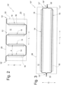
- Fig. 2 shows a top view, approximately according to view arrow II in Fig. 1 , to a slightly modified embodiment of an intermediate product 10', in which the pipe system 13' is also meander-shaped, but provides more than two straight sections 14, namely four.
- each of the straight sections 14 is overlapped by a heat-conducting element 16, e.g., in the form of a heat-conducting plate.
- a heat-conducting element 16 e.g., in the form of a heat-conducting plate.
- the pipe system 13' is secured to the support plate 11'.
- the extension of the support plate 11' in the longitudinal direction L is naturally larger than in Fig. 1 , while, for example, the extension in the transverse direction Q corresponds to that according to the embodiment according to Fig. 1 identical.
- FIG. 2 Another difference of the intermediate 10' compared to the intermediate 10 according to Fig. 1 is that, as in Fig. 2 As shown, the ends 19' of the pipe system 13' slightly protrude beyond the edge 20 of the support plate 11'. Nevertheless, the pipe system 13' is also essentially located within the contour of the support plate 11'.
- Fig. 2 It should be noted that the pipe spacing a, i.e. the distance between two parallel, straight pipe sections 14, is basically the same as that of Fig. 1 In the illustrated embodiment, however, this distance a is slightly larger - purely for exemplary reasons - in order to illustrate the variability of the different intermediate products.
- FIG. 3 shows a further embodiment of an intermediate product 10" according to the invention, in which the pipe system 13" is not designed in a meandering shape, but rather “harp-like".
- the illustrated "harp shape” also looks (as Fig. 1 ) two straight pipe sections 14. However, these do not extend in the transverse direction Q, but rather in the longitudinal direction L, so that, especially with long carrier plates 11", form particularly long straight sections 14.
- Fig. 3 is to be understood as merely exemplary. If, for example, a carrier plate wider in the transverse direction Q were used, then typically more than two parallel sections 14 would be provided, namely, for example, three or more. All straight sections 14 in a harp shape typically end in a common end region 19" (or in two of them), and are thus joined. The end 19" can in particular be Fig. 3
- the attachment element 22 shown as an example can be assigned for further connection of the system to a (particularly single) guide pipe.
- the connecting piece 22 can be considered either as part of the pipe system 13" or not. Regardless of this, Fig. 3 that part of the 13" pipe system also protrudes beyond the contour of the 11" support plate.
- a production site 23 which may be, for example, a production building or a factory or similar
- it is typically not installed there, but is transported to another location 24 for the purpose of installing the underfloor heating and there, according to the Fig. 4 or 5 used.
- This location 24 can, for example, be a building or a room that is to be equipped with underfloor heating (although, of course, open spaces to be heated, such as terraces or similar, are also possible).
- This first location 24 is typically located away from the production site or second location 23. Therefore, a distance of several (hundreds) kilometers must typically be bridged.
- the intermediate products 10 can be Fig. 1 to 3 in particular by means of transport, such as vehicles or similar, from the second place to the first place.
- the underfloor heating to be installed at the first location 24 can first be planned (in a manner to be described in more detail later), and specific intermediate products 10 can be requested from the first location 24.
- the underfloor heating can be switched on, for example as shown in the Fig. 4a and 4b shown, set up.
- Fig. 4a and 4b show a cross-section through an intermediate product 10 placed on a raw floor 25.
- the intermediate product 10 can be (only as an example) the intermediate product 10 from Fig. 1 (naturally, however, all other intermediates according to the invention, in particular those according to Fig. 2 and 3 , can be used in an identical process).
- the sectional view of the intermediate product 10 corresponds approximately to the section line IV in Fig. 1 .
- FIG. 4a Also in the cross section according to Fig. 4a
- the pipe system 13 can be seen, namely as a section through the straight sections 14' and 14.
- the sections 14 and 14' are shown Fig. 4a each arranged with a heat conducting element 16 on the carrier plate 11.
- the support plate 11 rests with its underside 32 on the upper side 26 of the raw floor 25.
- the raw floor can include the pure concrete floor and possibly other elements such as insulation materials, protective foils or similar, which, for the sake of clarity, are all included in the Figs. 4 and 5 are not shown.
- the intermediate product 10 is essentially secured against slipping due to its greater weight (compared to a plastic pipe and due to the carrier plate), whereby the intermediate product 10 is fixed in its position at the latest when connected to further pipes and/or intermediate products.
- intermediate product 10 After the intermediate product 10 has been placed, further intermediate products 10 are laid in the space to be equipped, if necessary, and these intermediate products are then connected, for example via separate pipes or connecting pieces or the like.
- the intermediate product 10 can be poured with a flowable screed in a further step, which is already done in Fig. 4a indicated by arrow 27.
- the underfloor heating is shown by the Fig. 4 (but also the one described below Fig. 5 ) is produced in a wet process, in which the intermediate product 10 comes into contact with still liquid, at least flowable, screed material and according to Fig. 4a is poured over.
- the screed 28 then surrounds the intermediate product 10, and in particular the pipe system 13.
- the upper surface 29 of the screed layer can be walked on directly after drying, and a floor covering or an insulating layer, particularly for acoustic insulation, or similar, can then be applied to it.
- Walkable (exposed) screed can also be used, which is used directly as a room floor without a floor covering.
- Fig. 4b shows that the layer thickness of the screed has a height of l, while the intermediate product 10 has a height h, where h ⁇ l.
- the screed layer thickness l is chosen such that the intermediate product 10 "sinks" completely into the screed.
- Fig. 4b recognize that the screed 28 also reaches the intermediate space 30 between the two straight pipe sections 14 and 14', which is in particular assigned to the connecting area 21 of the support plate 11.
- FIG. 5 Another example of how to install underfloor heating is shown Fig. 5 : This is how Fig. 5a a so-called immersion screed 31, which can be a conventional screed 28 with more or less special properties, freshly poured, which can be seen on the wavy surface in Fig. 5a can be seen.
- the intermediate product 10 can be introduced into this immersion screed 31, typically with the underside 32, on which the pipe system 13 is arranged in this example, facing forward.
- the intermediate product is, like the figure transition from Fig. 5a to Fig. 5b points, along the arrow in Fig. 5a immersed in the immersion screed 31, in particular until a predetermined immersion depth is reached or until the heat-conducting element 16 abuts the upper side 26 of the subfloor 25 (this is not shown in the figures solely for the sake of clarity).
- a smooth floor surface 29 is also obtained, which completely covers the intermediate product 10, so that the intermediate product 10 is completely surrounded by screed 31.
- Fig. 5b shows an alternative.
- an alternative top surface 29' of the finished floor is indicated by dashed lines, which runs flush with the top surface 12 of the intermediate product 10, which in this example would also form part of the walkable floor (although this variant is likely only considered if an additional floor covering is used).
- the pipe system 13 is completely laid in the screed 31.
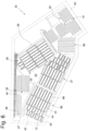
- Fig. 6 an exemplary first location 24, i.e. a place of installation for the underfloor heating 33.
- the exemplary place of installation 24 is therefore, for example, a building floor or a building room 24, which is in Fig. 6 with outer walls 34 and dividing walls 35.
- Fig. 6 shows the underfloor heating system 33 according to the invention without the screed layer (and any elements attached thereto such as floor covering or acoustic insulation or the like), in particular in order to demonstrate the use of intermediate products according to the invention and other pipe systems in the underfloor heating system 33 according to the invention.
- the living space 24 shown can be divided into different sections 36 to 41, which are divided in particular by the partition walls 35 or whose division is subject to other considerations.
- a first region 36 is provided, by way of example, with several intermediate products according to the invention of different longitudinal and/or transverse extensions.
- this region 36 comprises the intermediate product 10 according to the invention according to Fig. 1
- This intermediate product 42 is adjacent in the longitudinal direction L to another intermediate product 42 (of identical transverse length or width but different length).
- Intermediate product 42 for example, has five straight sections.
- the two intermediate products 10 and 42 are directly connected to each other in terms of flow, for example by means of an intermediate piece or similar (not shown in detail).
- intermediate product 10 is also connected via an additional line section 43 to another intermediate product 44, which also has the same transverse length but is even longer in the longitudinal direction (with the same pipe spacing, in particular with seven straight sections).
- This intermediate product 44 is then connected to a further intermediate product 45, which, while having the same length in the longitudinal direction, differs from the intermediate product 44 in its transverse length and is approximately twice as wide (the carrier plate of the intermediate product 45 thus has approximately twice the area of the intermediate product 44).
- the area 36 is then completed by a final intermediate product 46, which is essentially identical to the intermediate product 45.
- All intermediate products of area 36 are connected to a pipe system of the underfloor heating system 33 (not shown) via a common supply line or discharge line 47 and 48.
- Comparable intermediate products and a comparable structure can also be found for areas 37 (two intermediate products 10' are installed here) and 39 of location 24.
- Areas 38, 40 and 41 differ from the other areas in that the prefabricated intermediate products cannot be used here without further ado, for example because the areas are too narrow, sloping wall surfaces are provided or similar.
- auxiliary pipe systems 49 which do not have a support plate.
- auxiliary pipe systems 49 can in particular be connected to the intermediate products and/or independently to the central supply and discharge lines of the underfloor heating system 33.
- the auxiliary pipe systems 49 have in the embodiment according to Fig. 6 all also have a meander shape and may, for example, have been prefabricated at the second location 23 and/or delivered together with the intermediate products to the first location 24. Alternatively, they may also have been manufactured on site, i.e., at location 24, and, for example, bent into the required shape.
- Such a use case can arise, for example, if, for a location 24, it was initially planned that certain areas 36, 37, and 39 should be provided with underfloor heating, the corresponding intermediate products were ordered, and then it is discovered that other areas 38, 40, and 41 should also be covered by the underfloor heating, whereby a short-term order for further intermediate products may not even be possible.
- the Fig. 6 Use the process described, in which prefabricated intermediate products are supplemented by carrier plate-free pipe systems.
- the screed can then be poured at the location 24.
- the underfloor heating 33 is Fig. 6 in particular a system which was manufactured approximately according to the process described in Fig. 4 is shown.
- Both the intermediate products and the auxiliary pipe systems 49 are typically completely embedded in the screed.
- a method according to the invention can also include the step of planning the underfloor heating system:
- a map of the location 24 can first be created, optionally including the marking of external walls and/or partition walls. This map can then be used to create a plan indicating which intermediate products are required and/or where they are to be located. Finally, this plan can also be used to identify areas in which auxiliary piping systems are to be used.
- Such planning can be carried out using a software program (e.g., an app), which gives the user access to prefabricated intermediate products.
- a software program e.g., an app
- the user can, for example, virtually position these intermediate products on the plan within the software and thus identify areas suitable for intermediate products (and those in which auxiliary piping systems should be used).
- Such software can then also be connected to an e-commerce system of the intermediate product manufacturer, so that intermediate products required for a planned underfloor heating system can be ordered directly online.
Landscapes
- Engineering & Computer Science (AREA)
- Physics & Mathematics (AREA)
- Thermal Sciences (AREA)
- Chemical & Material Sciences (AREA)
- Combustion & Propulsion (AREA)
- Mechanical Engineering (AREA)
- General Engineering & Computer Science (AREA)
- Floor Finish (AREA)
- Steam Or Hot-Water Central Heating Systems (AREA)
Claims (11)
- Procédé destiné à mettre en place un chauffage au sol (33), comprenant les étapes :• finaliser un produit intermédiaire (10), comprenant une plaque de support (11) en métal, en particulier rectangulaire, sur un côté (12, 32) de laquelle est fixé un système de tuyaux (13) en métal, pour guider un milieu d'au moins un élément conducteur de chaleur (16),caractérisé en ce que le procédé comprend l'étape suivante :• remplir avec une chape coulée (28, 31) un espace intermédiaire (30) formé par le système de tuyaux (13).
- Procédé selon la revendication 1, caractérisé en ce que le remplissage s'effectue par la coulée (27) de la chape (28) sur le produit intermédiaire (10), dans lequel le système de tuyaux (13) est disposé en particulier sur la face supérieure (12) de la plaque de support en métal (11).
- Procédé selon la revendication 1, caractérisé en ce que le remplissage s'effectue par l'immersion du produit intermédiaire (10) dans la chape coulée (31), dans lequel le système de tuyaux (13) est disposé en particulier sur la face inférieure (32) de la plaque de support en métal.
- Procédé selon une des revendications précédentes, caractérisé en ce que le système de tuyaux (13) du produit intermédiaire est disposé sensiblement à l'intérieur du contour de la plaque de support (11), en particulier sur au moins 75 %, encore plus particulièrement sur au moins 90 %.
- Procédé selon une des revendications précédentes, caractérisé en ce que le système de tuyaux (13) présente au moins une section droite (14) qui repose sensiblement sur toute sa longueur sur la plaque de support (11), de préférence même au moins deux de telles sections (14).
- Procédé selon une des revendications précédentes, caractérisé en ce que la plaque de support (11) est composée en (tôle) aluminium et/ou présente une épaisseur d'au moins 0,3 mm, en particulier d'au moins 0,4 mm ou d'au moins 0,5 mm, et/ou le système de tuyaux (13) est composé en cuivre.
- Procédé selon une des revendications précédentes, caractérisé en ce que le chauffage au sol (33) est installé respectivement finalisé au niveau d'un premier emplacement (24), au niveau duquel en particulier s'effectue le remplissage de l'espace intermédiaire (30), dans lequel la finalisation du produit intermédiaire (10) s'effectue au niveau d'un second emplacement distant (23), en particulier comprenant une étape de procédé destinée à transférer le produit intermédiaire (10) du second emplacement (23) vers le premier (24).
- Procédé selon une des revendications précédentes, caractérisé en ce que, dans une zone (38, 40, 41) de la surface à desservir par le chauffage au sol (33) où aucun produit intermédiaire (10) n'est prévu, un système de tuyaux (49) en métal, en particulier sinueux, est posé, lequel n'est pas disposé sur une plaque de support (11).
- Procédé selon une des revendications précédentes, caractérisé par l'étape de procédé :• relier le produit intermédiaire (10) en tant que partie du montage de chauffage avec au moins un autre produit intermédiaire (42, 44) fabriqué sensiblement de manière identique.
- Chauffage au sol (33), comprenant au moins un produit intermédiaire (10) pour la mise en place d'un chauffage au sol (33), en particulier destiné à une utilisation selon un des procédés précédents, dans lequel le produit intermédiaire (10) comprend un système de tuyaux (13) en métal, au moins un élément conducteur de chaleur (16) et une plaque de support (11) en métal, dans lequel sur un côté (12, 32) de la plaque de support (11) est fixé le système de tuyaux (13) en métal, pour guider un milieu de l'au moins un élément conducteur de chaleur (16),caractérisé en ce qu'un espace intermédiaire (30) du système de tuyaux (13) du produit intermédiaire (10) est rempli d'une chape coulée (28, 31).
- Chauffage au sol (33) selon la revendication 10, caractérisé en ce que, dans une zone (38, 40, 41) du chauffage au sol (33) où aucun produit intermédiaire (10) n'est prévu, un système de tuyaux (49) en métal, en particulier sinueux, est posé, lequel n'est pas disposé sur une plaque de support (11).
Applications Claiming Priority (1)
| Application Number | Priority Date | Filing Date | Title |
|---|---|---|---|
| DE102020112309.4A DE102020112309A1 (de) | 2020-05-06 | 2020-05-06 | Verfahren zur Einrichtung einer Fußbodenheizung, selbige und Zwischenprodukt hierfür |
Publications (2)
| Publication Number | Publication Date |
|---|---|
| EP3907433A1 EP3907433A1 (fr) | 2021-11-10 |
| EP3907433B1 true EP3907433B1 (fr) | 2025-04-16 |
Family
ID=75659856
Family Applications (1)
| Application Number | Title | Priority Date | Filing Date |
|---|---|---|---|
| EP21170058.8A Active EP3907433B1 (fr) | 2020-05-06 | 2021-04-23 | Procédé de mise en place d'un chauffage au sol et chauffage au sol |
Country Status (2)
| Country | Link |
|---|---|
| EP (1) | EP3907433B1 (fr) |
| DE (1) | DE102020112309A1 (fr) |
Citations (1)
| Publication number | Priority date | Publication date | Assignee | Title |
|---|---|---|---|---|
| EP1512933A2 (fr) * | 2003-09-04 | 2005-03-09 | Sgl Carbon Ag | Plate conductrice de chaleur en graphite expansé et sa méthode de fabrication |
Family Cites Families (6)
| Publication number | Priority date | Publication date | Assignee | Title |
|---|---|---|---|---|
| FR2483593A1 (fr) * | 1980-05-28 | 1981-12-04 | Sodeba Sarl | Elements-diffuseurs pour dispositifs climatiseurs par surfaces |
| DE3203964C2 (de) | 1982-02-05 | 1985-10-17 | Wilhelm Friedrich 7900 Ulm Korner | Abzweigeeinheit für eine Heizungs- oder Kühlanlage |
| DE29723649U1 (de) | 1997-08-19 | 1998-11-19 | Hewing GmbH, 48607 Ochtrup | Rohrverlegeelement insbesondere für Flächenheizungen, wie beispielweise Fußbodenheizungen |
| DE29715643U1 (de) * | 1997-08-30 | 1999-01-07 | Reckzeh, Manfred, 63457 Hanau | Baueinheit zur Erstellung einer Raumheizungs- bzw. Kühlungsanlage |
| KR100523690B1 (ko) * | 2002-10-08 | 2005-10-25 | 정영숙 | 온수배관에 설치되는 콘크리트보강용 열전달판 |
| DE102004014468B4 (de) * | 2004-03-24 | 2008-05-29 | Mi-Heiztechnik Gmbh | Fußbodenheizung |
-
2020
- 2020-05-06 DE DE102020112309.4A patent/DE102020112309A1/de not_active Ceased
-
2021
- 2021-04-23 EP EP21170058.8A patent/EP3907433B1/fr active Active
Patent Citations (1)
| Publication number | Priority date | Publication date | Assignee | Title |
|---|---|---|---|---|
| EP1512933A2 (fr) * | 2003-09-04 | 2005-03-09 | Sgl Carbon Ag | Plate conductrice de chaleur en graphite expansé et sa méthode de fabrication |
Also Published As
| Publication number | Publication date |
|---|---|
| EP3907433A1 (fr) | 2021-11-10 |
| DE102020112309A1 (de) | 2021-11-11 |
Similar Documents
| Publication | Publication Date | Title |
|---|---|---|
| DE202010016878U1 (de) | Aufbau eines Wärme leitenden Flächenelementes | |
| AT414000B (de) | Auflageleiste, heiz- bzw. kühlregister sowie flächiger bauteil aus aushärtbarem werkstoff | |
| DE102008005491A1 (de) | Verfahren zur Herstellung eines transportablen vorgefertigten Verbundwandelements aus Schalungssteinen | |
| DE19950356C2 (de) | Mehrschichtige Bauplatte, sowie Verfahren zu ihrer Herstellung | |
| EP3907433A1 (fr) | Procédé de mise en place d'un chauffage au sol, chauffage au sol et produit intermédiaire correspondant | |
| DE19930693C1 (de) | Verfahren zur Herstellung einer Betondecke | |
| DE102005005755A1 (de) | Einrichtung zum Temperieren von Räumen | |
| EP1302604B1 (fr) | Element de plafond et de mur | |
| EP1006318A1 (fr) | Installation pour chauffer et/ou réfrigérer des locaux | |
| EP2574852B1 (fr) | Procédé de fabrication de chauffages au sol de grande taille et chauffage au sol fabriqué selon ce procédé | |
| DE10253867B4 (de) | Vorrichtung zum Austausch von Wärme und/oder Kälte mit Feststoffen oder Feststoffgemischen | |
| DE20221176U1 (de) | Decken- und Wandelement | |
| DE202008000239U1 (de) | Wärmetauschersystem für ein Gebäude | |
| DE202008002169U1 (de) | Einbauverbundsystem | |
| EP0028840A2 (fr) | Disposition pour l'admission de chaleur au circuit primaire d'une installation de chauffage à pompe à chaleur | |
| DE202016005254U1 (de) | Vorgefertigtes Deckenelement | |
| EP0770827B1 (fr) | Paroi thermo-réglable et méthode de fabrication de la paroi | |
| EP2479358B1 (fr) | Procédé destiné à la fabrication d'un sol en préfabriqué | |
| DE20315885U1 (de) | Klima-Filigrandeckenplatte | |
| EP4063589B1 (fr) | Élément de coffrage pour une construction en béton, procede de production un tel coffrage et un procede de coffrage | |
| EP2450636A2 (fr) | Elément de support de revêtement de sol et agencement de revêtement de sol doté d'un élément de support de revêtement de sol | |
| EP3832045B1 (fr) | Procédé de fabrication d'un raccordement d'un élément composite bois-béton plan avec au moins une partie d'une structure en bois | |
| DE102016112459A1 (de) | Baukastensystem zur Erstellung eines Fertighauses und Verfahren zu dessen Herstellung | |
| CH721096A2 (de) | Unterlagsboden, insbesondere mit einer Bodenheizung | |
| EP3315682A1 (fr) | Élément de coffrage et procédé de fabrication d'un plafond de bâtiment |
Legal Events
| Date | Code | Title | Description |
|---|---|---|---|
| PUAI | Public reference made under article 153(3) epc to a published international application that has entered the european phase |
Free format text: ORIGINAL CODE: 0009012 |
|
| STAA | Information on the status of an ep patent application or granted ep patent |
Free format text: STATUS: THE APPLICATION HAS BEEN PUBLISHED |
|
| AK | Designated contracting states |
Kind code of ref document: A1 Designated state(s): AL AT BE BG CH CY CZ DE DK EE ES FI FR GB GR HR HU IE IS IT LI LT LU LV MC MK MT NL NO PL PT RO RS SE SI SK SM TR |
|
| B565 | Issuance of search results under rule 164(2) epc |
Effective date: 20211007 |
|
| STAA | Information on the status of an ep patent application or granted ep patent |
Free format text: STATUS: REQUEST FOR EXAMINATION WAS MADE |
|
| 17P | Request for examination filed |
Effective date: 20220505 |
|
| RBV | Designated contracting states (corrected) |
Designated state(s): AL AT BE BG CH CY CZ DE DK EE ES FI FR GB GR HR HU IE IS IT LI LT LU LV MC MK MT NL NO PL PT RO RS SE SI SK SM TR |
|
| STAA | Information on the status of an ep patent application or granted ep patent |
Free format text: STATUS: EXAMINATION IS IN PROGRESS |
|
| 17Q | First examination report despatched |
Effective date: 20240612 |
|
| GRAP | Despatch of communication of intention to grant a patent |
Free format text: ORIGINAL CODE: EPIDOSNIGR1 |
|
| STAA | Information on the status of an ep patent application or granted ep patent |
Free format text: STATUS: GRANT OF PATENT IS INTENDED |
|
| INTG | Intention to grant announced |
Effective date: 20241211 |
|
| GRAS | Grant fee paid |
Free format text: ORIGINAL CODE: EPIDOSNIGR3 |
|
| GRAA | (expected) grant |
Free format text: ORIGINAL CODE: 0009210 |
|
| STAA | Information on the status of an ep patent application or granted ep patent |
Free format text: STATUS: THE PATENT HAS BEEN GRANTED |
|
| AK | Designated contracting states |
Kind code of ref document: B1 Designated state(s): AL AT BE BG CH CY CZ DE DK EE ES FI FR GB GR HR HU IE IS IT LI LT LU LV MC MK MT NL NO PL PT RO RS SE SI SK SM TR |
|
| REG | Reference to a national code |
Ref country code: GB Ref legal event code: FG4D Free format text: NOT ENGLISH |
|
| REG | Reference to a national code |
Ref country code: CH Ref legal event code: EP Ref country code: DE Ref legal event code: R096 Ref document number: 502021007202 Country of ref document: DE |
|
| REG | Reference to a national code |
Ref country code: IE Ref legal event code: FG4D Free format text: LANGUAGE OF EP DOCUMENT: GERMAN |
|
| PGFP | Annual fee paid to national office [announced via postgrant information from national office to epo] |
Ref country code: DE Payment date: 20250429 Year of fee payment: 5 |
|
| PGFP | Annual fee paid to national office [announced via postgrant information from national office to epo] |
Ref country code: AT Payment date: 20250721 Year of fee payment: 5 |
|
| REG | Reference to a national code |
Ref country code: NL Ref legal event code: MP Effective date: 20250416 |
|
| PG25 | Lapsed in a contracting state [announced via postgrant information from national office to epo] |
Ref country code: NL Free format text: LAPSE BECAUSE OF FAILURE TO SUBMIT A TRANSLATION OF THE DESCRIPTION OR TO PAY THE FEE WITHIN THE PRESCRIBED TIME-LIMIT Effective date: 20250416 |
|
| PG25 | Lapsed in a contracting state [announced via postgrant information from national office to epo] |
Ref country code: ES Free format text: LAPSE BECAUSE OF FAILURE TO SUBMIT A TRANSLATION OF THE DESCRIPTION OR TO PAY THE FEE WITHIN THE PRESCRIBED TIME-LIMIT Effective date: 20250416 Ref country code: FI Free format text: LAPSE BECAUSE OF FAILURE TO SUBMIT A TRANSLATION OF THE DESCRIPTION OR TO PAY THE FEE WITHIN THE PRESCRIBED TIME-LIMIT Effective date: 20250416 Ref country code: PT Free format text: LAPSE BECAUSE OF FAILURE TO SUBMIT A TRANSLATION OF THE DESCRIPTION OR TO PAY THE FEE WITHIN THE PRESCRIBED TIME-LIMIT Effective date: 20250818 |
|
| REG | Reference to a national code |
Ref country code: LT Ref legal event code: MG9D |
|
| PG25 | Lapsed in a contracting state [announced via postgrant information from national office to epo] |
Ref country code: NO Free format text: LAPSE BECAUSE OF FAILURE TO SUBMIT A TRANSLATION OF THE DESCRIPTION OR TO PAY THE FEE WITHIN THE PRESCRIBED TIME-LIMIT Effective date: 20250716 Ref country code: GR Free format text: LAPSE BECAUSE OF FAILURE TO SUBMIT A TRANSLATION OF THE DESCRIPTION OR TO PAY THE FEE WITHIN THE PRESCRIBED TIME-LIMIT Effective date: 20250717 |
|
| PG25 | Lapsed in a contracting state [announced via postgrant information from national office to epo] |
Ref country code: PL Free format text: LAPSE BECAUSE OF FAILURE TO SUBMIT A TRANSLATION OF THE DESCRIPTION OR TO PAY THE FEE WITHIN THE PRESCRIBED TIME-LIMIT Effective date: 20250416 |
|
| PG25 | Lapsed in a contracting state [announced via postgrant information from national office to epo] |
Ref country code: BG Free format text: LAPSE BECAUSE OF FAILURE TO SUBMIT A TRANSLATION OF THE DESCRIPTION OR TO PAY THE FEE WITHIN THE PRESCRIBED TIME-LIMIT Effective date: 20250416 |
|
| PG25 | Lapsed in a contracting state [announced via postgrant information from national office to epo] |
Ref country code: HR Free format text: LAPSE BECAUSE OF FAILURE TO SUBMIT A TRANSLATION OF THE DESCRIPTION OR TO PAY THE FEE WITHIN THE PRESCRIBED TIME-LIMIT Effective date: 20250416 |
|
| PG25 | Lapsed in a contracting state [announced via postgrant information from national office to epo] |
Ref country code: RS Free format text: LAPSE BECAUSE OF FAILURE TO SUBMIT A TRANSLATION OF THE DESCRIPTION OR TO PAY THE FEE WITHIN THE PRESCRIBED TIME-LIMIT Effective date: 20250716 |
|
| PG25 | Lapsed in a contracting state [announced via postgrant information from national office to epo] |
Ref country code: IS Free format text: LAPSE BECAUSE OF FAILURE TO SUBMIT A TRANSLATION OF THE DESCRIPTION OR TO PAY THE FEE WITHIN THE PRESCRIBED TIME-LIMIT Effective date: 20250816 |
|
| PG25 | Lapsed in a contracting state [announced via postgrant information from national office to epo] |
Ref country code: LV Free format text: LAPSE BECAUSE OF FAILURE TO SUBMIT A TRANSLATION OF THE DESCRIPTION OR TO PAY THE FEE WITHIN THE PRESCRIBED TIME-LIMIT Effective date: 20250416 |
|
| REG | Reference to a national code |
Ref country code: CH Ref legal event code: H13 Free format text: ST27 STATUS EVENT CODE: U-0-0-H10-H13 (AS PROVIDED BY THE NATIONAL OFFICE) Effective date: 20251125 |
|
| PG25 | Lapsed in a contracting state [announced via postgrant information from national office to epo] |
Ref country code: LU Free format text: LAPSE BECAUSE OF NON-PAYMENT OF DUE FEES Effective date: 20250423 |
|
| REG | Reference to a national code |
Ref country code: BE Ref legal event code: MM Effective date: 20250430 |
|
| PG25 | Lapsed in a contracting state [announced via postgrant information from national office to epo] |
Ref country code: SM Free format text: LAPSE BECAUSE OF FAILURE TO SUBMIT A TRANSLATION OF THE DESCRIPTION OR TO PAY THE FEE WITHIN THE PRESCRIBED TIME-LIMIT Effective date: 20250416 Ref country code: DK Free format text: LAPSE BECAUSE OF FAILURE TO SUBMIT A TRANSLATION OF THE DESCRIPTION OR TO PAY THE FEE WITHIN THE PRESCRIBED TIME-LIMIT Effective date: 20250416 |
|
| PG25 | Lapsed in a contracting state [announced via postgrant information from national office to epo] |
Ref country code: BE Free format text: LAPSE BECAUSE OF NON-PAYMENT OF DUE FEES Effective date: 20250430 |
|
| PG25 | Lapsed in a contracting state [announced via postgrant information from national office to epo] |
Ref country code: CH Free format text: LAPSE BECAUSE OF NON-PAYMENT OF DUE FEES Effective date: 20250430 |
|
| REG | Reference to a national code |
Ref country code: DE Ref legal event code: R097 Ref document number: 502021007202 Country of ref document: DE |
|
| PG25 | Lapsed in a contracting state [announced via postgrant information from national office to epo] |
Ref country code: CZ Free format text: LAPSE BECAUSE OF FAILURE TO SUBMIT A TRANSLATION OF THE DESCRIPTION OR TO PAY THE FEE WITHIN THE PRESCRIBED TIME-LIMIT Effective date: 20250416 |
|
| PG25 | Lapsed in a contracting state [announced via postgrant information from national office to epo] |
Ref country code: EE Free format text: LAPSE BECAUSE OF FAILURE TO SUBMIT A TRANSLATION OF THE DESCRIPTION OR TO PAY THE FEE WITHIN THE PRESCRIBED TIME-LIMIT Effective date: 20250416 |
|
| PG25 | Lapsed in a contracting state [announced via postgrant information from national office to epo] |
Ref country code: SK Free format text: LAPSE BECAUSE OF FAILURE TO SUBMIT A TRANSLATION OF THE DESCRIPTION OR TO PAY THE FEE WITHIN THE PRESCRIBED TIME-LIMIT Effective date: 20250416 Ref country code: RO Free format text: LAPSE BECAUSE OF FAILURE TO SUBMIT A TRANSLATION OF THE DESCRIPTION OR TO PAY THE FEE WITHIN THE PRESCRIBED TIME-LIMIT Effective date: 20250416 |
|
| PG25 | Lapsed in a contracting state [announced via postgrant information from national office to epo] |
Ref country code: IT Free format text: LAPSE BECAUSE OF FAILURE TO SUBMIT A TRANSLATION OF THE DESCRIPTION OR TO PAY THE FEE WITHIN THE PRESCRIBED TIME-LIMIT Effective date: 20250416 |
|
| PG25 | Lapsed in a contracting state [announced via postgrant information from national office to epo] |
Ref country code: MC Free format text: LAPSE BECAUSE OF FAILURE TO SUBMIT A TRANSLATION OF THE DESCRIPTION OR TO PAY THE FEE WITHIN THE PRESCRIBED TIME-LIMIT Effective date: 20250416 |
|
| PLBE | No opposition filed within time limit |
Free format text: ORIGINAL CODE: 0009261 |
|
| STAA | Information on the status of an ep patent application or granted ep patent |
Free format text: STATUS: NO OPPOSITION FILED WITHIN TIME LIMIT |
|
| REG | Reference to a national code |
Ref country code: CH Ref legal event code: L10 Free format text: ST27 STATUS EVENT CODE: U-0-0-L10-L00 (AS PROVIDED BY THE NATIONAL OFFICE) Effective date: 20260225 |
|
| 26N | No opposition filed |
Effective date: 20260119 |
|
| GBPC | Gb: european patent ceased through non-payment of renewal fee |
Effective date: 20250716 |
|
| PG25 | Lapsed in a contracting state [announced via postgrant information from national office to epo] |
Ref country code: GB Free format text: LAPSE BECAUSE OF NON-PAYMENT OF DUE FEES Effective date: 20250716 |
|
| PG25 | Lapsed in a contracting state [announced via postgrant information from national office to epo] |
Ref country code: IE Free format text: LAPSE BECAUSE OF NON-PAYMENT OF DUE FEES Effective date: 20250423 |
|
| PG25 | Lapsed in a contracting state [announced via postgrant information from national office to epo] |
Ref country code: FR Free format text: LAPSE BECAUSE OF NON-PAYMENT OF DUE FEES Effective date: 20250616 |
|
| PG25 | Lapsed in a contracting state [announced via postgrant information from national office to epo] |
Ref country code: CY Free format text: LAPSE BECAUSE OF FAILURE TO SUBMIT A TRANSLATION OF THE DESCRIPTION OR TO PAY THE FEE WITHIN THE PRESCRIBED TIME-LIMIT Effective date: 20250416 |
|
| PG25 | Lapsed in a contracting state [announced via postgrant information from national office to epo] |
Ref country code: LT Free format text: LAPSE BECAUSE OF FAILURE TO SUBMIT A TRANSLATION OF THE DESCRIPTION OR TO PAY THE FEE WITHIN THE PRESCRIBED TIME-LIMIT Effective date: 20250416 |
|
| PG25 | Lapsed in a contracting state [announced via postgrant information from national office to epo] |
Ref country code: SE Free format text: LAPSE BECAUSE OF FAILURE TO SUBMIT A TRANSLATION OF THE DESCRIPTION OR TO PAY THE FEE WITHIN THE PRESCRIBED TIME-LIMIT Effective date: 20250416 |