EP3907812A1 - Sekundärbatterie, herstellungsverfahren für sekundärbatterie, und batteriemodul mit sekundärbatterie - Google Patents
Sekundärbatterie, herstellungsverfahren für sekundärbatterie, und batteriemodul mit sekundärbatterie Download PDFInfo
- Publication number
- EP3907812A1 EP3907812A1 EP20835100.7A EP20835100A EP3907812A1 EP 3907812 A1 EP3907812 A1 EP 3907812A1 EP 20835100 A EP20835100 A EP 20835100A EP 3907812 A1 EP3907812 A1 EP 3907812A1
- Authority
- EP
- European Patent Office
- Prior art keywords
- temperature sensing
- sensing units
- insulating film
- circuit unit
- secondary battery
- Prior art date
- Legal status (The legal status is an assumption and is not a legal conclusion. Google has not performed a legal analysis and makes no representation as to the accuracy of the status listed.)
- Pending
Links
Images


Classifications
-
- H—ELECTRICITY
- H01—ELECTRIC ELEMENTS
- H01M—PROCESSES OR MEANS, e.g. BATTERIES, FOR THE DIRECT CONVERSION OF CHEMICAL ENERGY INTO ELECTRICAL ENERGY
- H01M50/00—Constructional details or processes of manufacture of the non-active parts of electrochemical cells other than fuel cells, e.g. hybrid cells
- H01M50/50—Current conducting connections for cells or batteries
- H01M50/572—Means for preventing undesired use or discharge
- H01M50/574—Devices or arrangements for the interruption of current
- H01M50/581—Devices or arrangements for the interruption of current in response to temperature
-
- G—PHYSICS
- G01—MEASURING; TESTING
- G01R—MEASURING ELECTRIC VARIABLES; MEASURING MAGNETIC VARIABLES
- G01R31/00—Arrangements for testing electric properties; Arrangements for locating electric faults; Arrangements for electrical testing characterised by what is being tested not provided for elsewhere
- G01R31/36—Arrangements for testing, measuring or monitoring the electrical condition of accumulators or electric batteries, e.g. capacity or state of charge [SoC]
-
- H—ELECTRICITY
- H01—ELECTRIC ELEMENTS
- H01M—PROCESSES OR MEANS, e.g. BATTERIES, FOR THE DIRECT CONVERSION OF CHEMICAL ENERGY INTO ELECTRICAL ENERGY
- H01M10/00—Secondary cells; Manufacture thereof
- H01M10/04—Construction or manufacture in general
- H01M10/0404—Machines for assembling batteries
-
- H—ELECTRICITY
- H01—ELECTRIC ELEMENTS
- H01M—PROCESSES OR MEANS, e.g. BATTERIES, FOR THE DIRECT CONVERSION OF CHEMICAL ENERGY INTO ELECTRICAL ENERGY
- H01M10/00—Secondary cells; Manufacture thereof
- H01M10/42—Methods or arrangements for servicing or maintenance of secondary cells or secondary half-cells
- H01M10/425—Structural combination with electronic components, e.g. electronic circuits integrated to the outside of the casing
-
- H—ELECTRICITY
- H01—ELECTRIC ELEMENTS
- H01M—PROCESSES OR MEANS, e.g. BATTERIES, FOR THE DIRECT CONVERSION OF CHEMICAL ENERGY INTO ELECTRICAL ENERGY
- H01M10/00—Secondary cells; Manufacture thereof
- H01M10/42—Methods or arrangements for servicing or maintenance of secondary cells or secondary half-cells
- H01M10/425—Structural combination with electronic components, e.g. electronic circuits integrated to the outside of the casing
- H01M10/4257—Smart batteries, e.g. electronic circuits inside the housing of the cells or batteries
-
- H—ELECTRICITY
- H01—ELECTRIC ELEMENTS
- H01M—PROCESSES OR MEANS, e.g. BATTERIES, FOR THE DIRECT CONVERSION OF CHEMICAL ENERGY INTO ELECTRICAL ENERGY
- H01M10/00—Secondary cells; Manufacture thereof
- H01M10/42—Methods or arrangements for servicing or maintenance of secondary cells or secondary half-cells
- H01M10/48—Accumulators combined with arrangements for measuring, testing or indicating the condition of cells, e.g. the level or density of the electrolyte
- H01M10/486—Accumulators combined with arrangements for measuring, testing or indicating the condition of cells, e.g. the level or density of the electrolyte for measuring temperature
-
- H—ELECTRICITY
- H01—ELECTRIC ELEMENTS
- H01M—PROCESSES OR MEANS, e.g. BATTERIES, FOR THE DIRECT CONVERSION OF CHEMICAL ENERGY INTO ELECTRICAL ENERGY
- H01M10/00—Secondary cells; Manufacture thereof
- H01M10/60—Heating or cooling; Temperature control
- H01M10/65—Means for temperature control structurally associated with the cells
- H01M10/658—Means for temperature control structurally associated with the cells by thermal insulation or shielding
-
- H—ELECTRICITY
- H01—ELECTRIC ELEMENTS
- H01M—PROCESSES OR MEANS, e.g. BATTERIES, FOR THE DIRECT CONVERSION OF CHEMICAL ENERGY INTO ELECTRICAL ENERGY
- H01M50/00—Constructional details or processes of manufacture of the non-active parts of electrochemical cells other than fuel cells, e.g. hybrid cells
- H01M50/10—Primary casings; Jackets or wrappings
- H01M50/102—Primary casings; Jackets or wrappings characterised by their shape or physical structure
- H01M50/105—Pouches or flexible bags
-
- H—ELECTRICITY
- H01—ELECTRIC ELEMENTS
- H01M—PROCESSES OR MEANS, e.g. BATTERIES, FOR THE DIRECT CONVERSION OF CHEMICAL ENERGY INTO ELECTRICAL ENERGY
- H01M50/00—Constructional details or processes of manufacture of the non-active parts of electrochemical cells other than fuel cells, e.g. hybrid cells
- H01M50/10—Primary casings; Jackets or wrappings
- H01M50/116—Primary casings; Jackets or wrappings characterised by the material
-
- H—ELECTRICITY
- H01—ELECTRIC ELEMENTS
- H01M—PROCESSES OR MEANS, e.g. BATTERIES, FOR THE DIRECT CONVERSION OF CHEMICAL ENERGY INTO ELECTRICAL ENERGY
- H01M50/00—Constructional details or processes of manufacture of the non-active parts of electrochemical cells other than fuel cells, e.g. hybrid cells
- H01M50/10—Primary casings; Jackets or wrappings
- H01M50/116—Primary casings; Jackets or wrappings characterised by the material
- H01M50/124—Primary casings; Jackets or wrappings characterised by the material having a layered structure
-
- H—ELECTRICITY
- H01—ELECTRIC ELEMENTS
- H01M—PROCESSES OR MEANS, e.g. BATTERIES, FOR THE DIRECT CONVERSION OF CHEMICAL ENERGY INTO ELECTRICAL ENERGY
- H01M50/00—Constructional details or processes of manufacture of the non-active parts of electrochemical cells other than fuel cells, e.g. hybrid cells
- H01M50/50—Current conducting connections for cells or batteries
- H01M50/531—Electrode connections inside a battery casing
-
- H—ELECTRICITY
- H01—ELECTRIC ELEMENTS
- H01M—PROCESSES OR MEANS, e.g. BATTERIES, FOR THE DIRECT CONVERSION OF CHEMICAL ENERGY INTO ELECTRICAL ENERGY
- H01M50/00—Constructional details or processes of manufacture of the non-active parts of electrochemical cells other than fuel cells, e.g. hybrid cells
- H01M50/50—Current conducting connections for cells or batteries
- H01M50/572—Means for preventing undesired use or discharge
- H01M50/584—Means for preventing undesired use or discharge for preventing incorrect connections inside or outside the batteries
- H01M50/59—Means for preventing undesired use or discharge for preventing incorrect connections inside or outside the batteries characterised by the protection means
-
- H—ELECTRICITY
- H01—ELECTRIC ELEMENTS
- H01M—PROCESSES OR MEANS, e.g. BATTERIES, FOR THE DIRECT CONVERSION OF CHEMICAL ENERGY INTO ELECTRICAL ENERGY
- H01M10/00—Secondary cells; Manufacture thereof
- H01M10/42—Methods or arrangements for servicing or maintenance of secondary cells or secondary half-cells
- H01M10/425—Structural combination with electronic components, e.g. electronic circuits integrated to the outside of the casing
- H01M2010/4271—Battery management systems including electronic circuits, e.g. control of current or voltage to keep battery in healthy state, cell balancing
-
- H—ELECTRICITY
- H01—ELECTRIC ELEMENTS
- H01M—PROCESSES OR MEANS, e.g. BATTERIES, FOR THE DIRECT CONVERSION OF CHEMICAL ENERGY INTO ELECTRICAL ENERGY
- H01M10/00—Secondary cells; Manufacture thereof
- H01M10/42—Methods or arrangements for servicing or maintenance of secondary cells or secondary half-cells
- H01M10/425—Structural combination with electronic components, e.g. electronic circuits integrated to the outside of the casing
- H01M2010/4278—Systems for data transfer from batteries, e.g. transfer of battery parameters to a controller, data transferred between battery controller and main controller
-
- H—ELECTRICITY
- H01—ELECTRIC ELEMENTS
- H01M—PROCESSES OR MEANS, e.g. BATTERIES, FOR THE DIRECT CONVERSION OF CHEMICAL ENERGY INTO ELECTRICAL ENERGY
- H01M2200/00—Safety devices for primary or secondary batteries
- H01M2200/10—Temperature sensitive devices
- H01M2200/105—NTC
-
- H—ELECTRICITY
- H01—ELECTRIC ELEMENTS
- H01M—PROCESSES OR MEANS, e.g. BATTERIES, FOR THE DIRECT CONVERSION OF CHEMICAL ENERGY INTO ELECTRICAL ENERGY
- H01M2200/00—Safety devices for primary or secondary batteries
- H01M2200/10—Temperature sensitive devices
- H01M2200/106—PTC
-
- Y—GENERAL TAGGING OF NEW TECHNOLOGICAL DEVELOPMENTS; GENERAL TAGGING OF CROSS-SECTIONAL TECHNOLOGIES SPANNING OVER SEVERAL SECTIONS OF THE IPC; TECHNICAL SUBJECTS COVERED BY FORMER USPC CROSS-REFERENCE ART COLLECTIONS [XRACs] AND DIGESTS
- Y02—TECHNOLOGIES OR APPLICATIONS FOR MITIGATION OR ADAPTATION AGAINST CLIMATE CHANGE
- Y02E—REDUCTION OF GREENHOUSE GAS [GHG] EMISSIONS, RELATED TO ENERGY GENERATION, TRANSMISSION OR DISTRIBUTION
- Y02E60/00—Enabling technologies; Technologies with a potential or indirect contribution to GHG emissions mitigation
- Y02E60/10—Energy storage using batteries
-
- Y—GENERAL TAGGING OF NEW TECHNOLOGICAL DEVELOPMENTS; GENERAL TAGGING OF CROSS-SECTIONAL TECHNOLOGIES SPANNING OVER SEVERAL SECTIONS OF THE IPC; TECHNICAL SUBJECTS COVERED BY FORMER USPC CROSS-REFERENCE ART COLLECTIONS [XRACs] AND DIGESTS
- Y02—TECHNOLOGIES OR APPLICATIONS FOR MITIGATION OR ADAPTATION AGAINST CLIMATE CHANGE
- Y02P—CLIMATE CHANGE MITIGATION TECHNOLOGIES IN THE PRODUCTION OR PROCESSING OF GOODS
- Y02P70/00—Climate change mitigation technologies in the production process for final industrial or consumer products
- Y02P70/50—Manufacturing or production processes characterised by the final manufactured product
Definitions
- the present invention relates to a secondary battery, a method for manufacturing the secondary battery, and a battery module including the secondary battery, and more particularly, to a secondary battery having a structure which is capable of interrupting current when a temperature of the secondary battery exceeds a predetermined value, and a battery module including the secondary battery.
- Batteries storing electrical energy may be generally classified into primary batteries and a secondary batteries.
- Secondary batteries capable of being repeatedly chargeable and dischargeable need to be secured so that ignition or explosion does not occur when abnormal operation occurs. For example, when a temperature within a secondary battery exceeds a predetermined value due to short circuit or the like of the secondary battery, it is necessary to interrupt current from flowing through the secondary battery.
- the secondary battery may be classified into a cylindrical type secondary battery, a prismatic type battery secondary battery, a pouch type secondary battery, and the like according to its structure or manufacturing method.
- the pouch type secondary battery has a structure in which an electrode assembly having a structure in which electrodes and separators are alternately disposed in a sheet-shaped pouch exterior is accommodated.
- the pouch type secondary battery has been widely used due to its relatively simple process and low manufacturing cost.
- the pouch type secondary battery is not provided with a constitute that is capable of interrupting current when a temperature within the secondary battery abnormally increases.
- a secondary battery includes: an electrode assembly; a sheet-like exterior configured to accommodate the electrode assembly; and a plurality of temperature sensing units provided to be inserted into the exterior and configured to sense a temperature of one area of the exterior, wherein the exterior includes: an inner body part configured to define an inner body of the exterior; an insulating film attached on the inner body part to define an outer surface of the exterior, the insulating film having electrical insulation, wherein one or more of the plurality of temperature sensing units include: a positive temperature coefficient (PTC) element; and a negative temperature coefficient (NTC) element, wherein the plurality of temperature sensing units are attached to the inner body part, and the plurality of temperature sensing units are covered by the insulating film.
- PTC positive temperature coefficient
- NTC negative temperature coefficient
- the secondary battery may further include a circuit unit configured to electrically connect the plurality of temperature sensing units to each other, wherein the circuit unit may be attached on the inner body part, and the circuit may be covered by the insulating film.
- a recess part that is recessed upward may be defined in a bottom surface of the insulating film so that the plurality of temperature sensing units and the circuit unit are disposed, and distances between the inner body part of the exterior and an outer surface of the insulating film may be the same on (i) an area on which the plurality of temperature sensing units are disposed, (ii) an area on which the circuit unit is disposed, and (iii) an area on which the plurality of temperature sensing units and the circuit unit are not disposed.
- the secondary battery may further include an electrode lead having a shape that protrudes outward, wherein the NTC element may be provided in the temperature sensing unit, which is adjacent to the electrode lead, among the plurality of temperature sensing units.
- the electrode lead may include a positive electrode lead and a negative electrode lead, and the NTC element may be provided in the temperature sensing unit, which is adjacent to the negative electrode lead, among the plurality of temperature sensing units.
- the circuit unit may be configured to connect the plurality of temperature sensing units to each other in a zigzag shape.
- the insulating film may include: a first insulating film attached on the inner body part of the exterior, configured to wrap circumferences of the temperature sensing units and the circuit unit, and having a through-hole defined in a position at which the temperature sensing units and the circuit unit are disposed; and a second insulating film attached to a surface of an upper of the first insulating film to cover the temperature sensing units and the circuit unit.
- a battery module includes: the secondary battery; and a control unit configured to receive temperature information of the exterior on an area to which the temperature sensing units of the secondary battery are attached, wherein, when a temperature on a portion of the area to which the temperature sensing units are attached exceeds a predetermined value, the control unit (i) interrupts current of the secondary battery or (ii) transmits a warning signal to the outside.
- a method for manufacturing a secondary battery includes: an inner body part preparation step of preparing an inner body part forming an inner body of a sheet-like exterior; a sensing unit disposition step of disposing a plurality of temperature sensing units on the inner body part; and a film attachment step of attaching an insulating film on the inner body part to cover the plurality of temperature sensing units while wrapping circumferences of the plurality of temperature sensing units.
- One or more of the temperature sensing units may include: a PCT element; and an NTC element.
- the method may further include a circuit unit disposition step of disposing a circuit unit that electrically connects the plurality of temperature sensing units to each other on the inner body part, wherein the circuit unit disposition step may be performed after the sensing unit disposition step.
- the circuit unit may be disposed on the inner body part of the exterior in a deposition or printing manner.
- the insulating film may include a first insulating film and a second insulating film
- the film attachment step may include: a first film attachment step which is performed before the sensing unit disposition step and the circuit unit disposition step and in which the first insulating film having the through-hole is attached on the inner body part of the exterior; and a second film attachment step which is performed after the sensing unit disposition step and the circuit unit disposition step and in which the second insulating film is attached on a surface of an upper portion of the first insulating film to cover the plurality of temperature sensing units and the circuit unit, and in the sensing unit disposition step and the circuit unit disposition step, since the temperature sensing units and the circuit unit are disposed in the through-hole formed in the first insulating film, the first insulting film may wrap the circumferences of the temperature sensing units and the circuit unit.
- the current when the temperature within the pouch type secondary battery abnormally increases, the current may be interrupted to improve the safety.
- FIG. 1 is a plan view illustrating a structure of a secondary battery according to a first embodiment of the present invention
- FIG. 2 is a vertical cross-sectional view illustrating a structure of a surface of the secondary battery according to the present invention
- FIG. 3 is a plan view illustrating a structure of a secondary battery according to a second embodiment of the present invention
- FIG. 4 is a plan view illustrating a structure of a secondary battery according to a third embodiment of the present invention.
- a secondary battery 10 according to the present invention may include an electrode assembly and a sheet type exterior 200 (hereinafter, referred to as an 'exterior') that accommodates the electrode assembly.
- the electrode assembly may have a structure in which electrodes and separators are alternately arranged.
- the exterior 200 may include a body part 210, in which an internal space in which the electrode assembly is accommodated is defined, and a sealing part 220 that seals the internal space of the body part 210 from the outside.
- the sealing part 220 may have a structure in which two sheets are bonded to each other.
- a surface having a large area among surfaces of the body part 210 of the exterior 200 is referred to as a 'top surface' or a bottom surface', and a surface formed around the top surface or the bottom surface is referred to as a 'side surface'.
- an area of the body part 210 of the exterior 200 which is illustrated in FIGS. 1 and 3 , may be a top surface
- an area of the body part 210 of the exterior 200 which is illustrated in FIG. 4
- the secondary battery 10 may include an electrode lead 100 having a shape protruding to the outside.
- the electrode lead 100 may include a positive electrode lead 100a and a negative electrode lead 100b.
- the positive electrode lead 100a and the negative electrode lead 100b may be provided at one side of the exterior 200 to protrude in the same direction.
- the positive electrode lead 100a and the negative electrode lead 100b may be respectively provided at one side of the exterior 200 and the other side opposite to the one side to protrude in opposite directions.
- the secondary battery 10 may include a plurality of temperature sensing units 300 provided adjacent to the exterior 200.
- the temperature sensing units 300 may be provided in close contact with the exterior 200.
- each of the temperature sensing units 300 may be inserted into the exterior 200.
- the temperature sensing unit 300 may be configured to sense a temperature in one region of the exterior 200. As described below, information about a temperature in one region of the exterior 200 sensed by the temperature sensing units 300 may be provided to a control unit 20 (see FIG. 5 ).
- the plurality of temperature sensing units 300 may be disposed on a top or bottom surface of the exterior 200.
- the plurality of temperature sensing units 300 may be disposed on a side surface of the exterior 200.
- the secondary battery 10 may further include a circuit unit that electrically connects the plurality of temperature sensing units 300 to each other.
- the circuit unit 350 may connect the plurality of temperature sensing units 300 to each other in a zigzag shape.
- the circuit unit 350 may connect the plurality of temperature sensing units 300 in parallel to each other.
- the circuit unit 350 may also be inserted into the exterior 200.
- the secondary battery 10 may further include a terminal unit 400 disposed on a surface of the exterior 200 and connected to one of the plurality of temperature sensing units 300 by the circuit unit 350.
- FIGS. 1 , 3 , and 4 illustrate a case in which the terminal unit 400 is provided at one side of the exterior 200 on which the electrode lead 100 is disposed.
- each of the plurality of temperature sensing units 300 provided in the secondary battery 10 may include a positive temperature coefficient (PTC) element. Also, at least one of the plurality of temperature sensing units 300 may include a negative temperature coefficient (NTC) element. At least one of the plurality of temperature sensing units 300 may include the PTC element and the NTC element.
- PTC positive temperature coefficient
- NTC negative temperature coefficient
- the PTC element represents an element in which electrical resistance increases rapidly when the temperature increases
- the NTC element represents an element in which electrical resistance increases when the temperature decreases.
- the plurality of temperature sensing units since at least one of the plurality of temperature sensing units includes all the PTC element and the NTC element, more reliable information with respect to the temperature in a specific region of the exterior may be obtained.
- the temperature information in the specific region of the exterior is limited to information obtained from only one type of temperature measurement element.
- the temperature information obtained from one type of temperature measurement element is wrong, it is not known that the information is wrong, thereby deteriorating the reliability of the temperature information in the specific region of the exterior.
- At least one temperature sensing unit includes two types of temperature measurement elements (i.e., a PTC element and an NTC element)
- the temperature information in the specific region of the exterior may also be obtained through the two channels. If the temperature information obtained from one type of temperature measurement element is wrong, the error of the temperature information may be revealed through cross-checking of the information by using the temperature information obtained from the different type of temperature measurement elements.
- the reliability of information on the temperature in the specific region of the exterior may be improved.
- each of the plurality of temperature sensing units includes the NTC element, and at least one of the plurality of temperature sensing units includes the PTC element.
- the NTC element since the NTC element is more expensive than the PTC element, it may not be desirable in terms of economics when the temperature sensing units are configured in the above-described structure.
- the temperature sensing unit provided with two kinds of temperature measurement elements among the plurality of temperature sensing units is provided in a region in which the temperature is usually high in the secondary battery. This is because there is also high possibility of abnormal temperature increase at the position at which an amount of heat is large.
- a region in which the electrode assembly and the electrode lead are connected to each other generally has a relatively high temperature.
- a welding process is performed.
- a large amount of heat may be generated on an area on which materials different from each other are bonded to each other through the welding. This is because, when current flowing through the electrode assembly having a relatively large width flows through the electrode lead having a relatively narrow width, a large amount of heat is generated in the electrode lead due to an increase in electrical resistance due to the narrow width of the electrode lead.
- the NTC element may be provided in the temperature sensing unit adjacent to the electrode lead among the plurality of temperature sensing units 300.
- the NTC element may be provided in at least one of the upper temperature sensing units that are closest to the electrode lead 100 among the plurality of temperature sensing units 300.
- thermal conductivity of a material (for example, copper) used for the negative electrode lead is greater than that of a material (for example, aluminum) used for the positive electrode lead, it is common that a large amount of heat is generated in the negative electrode lead. Also, when the secondary battery is discharged, since charges flow from the negative electrode lead to the positive electrode lead, it is common that a relatively high temperature is generated on the area on which the negative electrode lead and the electrode assembly are electrically connected to each other.
- the NTC element may be provided in the temperature sensing unit adjacent to the negative electrode lead 100b among the plurality of temperature sensing units 300.
- the NTC element may be provided in the temperature sensing unit that is provided at a central portion in the upper temperature sensing units 300, which are closest to the negative electrode lead 100b, among the plurality of temperature sensing units 300.
- the secondary battery 10 may further include an insulating film 200a having electrical insulation.
- the insulating film 200a may form an outer surface of the exterior 200 on at least a partial area.
- the insulating film 200a may be a portion of the exterior 200.
- the exterior 200 may have a layered structure including an insulating film 200a and an inner body part 200b defining an inner body of the exterior 200, and the insulating film 200a may be attached on the inner body part 200b.
- the temperature sensing unit 300 and the circuit unit 350 may also be attached on the inner body part 200b of the exterior 200.
- the insulating film 200a may be provided to cover the plurality of temperature sensing units 300. That is, the plurality of temperature sensing units 300 may be covered by the insulating film 200a. Also, the insulating film 200a may be provided to cover the circuit unit 350. That is, the circuit unit 350 may also be covered by the insulating film 200a.
- the temperature sensing unit 300 and the circuit unit 350 may be attached to the inner body part 200b of the exterior 200. Since the insulating film 200a is provided to cover the plurality of temperature sensing units 300 and the circuit unit 350, an empty space in which the plurality of temperature sensing units 300 and the circuit unit 350 are provided may be defined inside the insulating film 200a.
- a recess part C that is recessed upward may be defined in a bottom surface of the insulating film 200a so that the plurality of temperature sensing units 300 and the circuit unit 350 are disposed.
- the recess part C may have a stepped shape corresponding to a difference in thickness between the temperature sensing unit 300 and the circuit unit 350.
- an area of the exterior 200, on which the insulating film 200a is disposed may be largely divided into (i) an area A1 on which the plurality of temperature sensing units are disposed, (ii) an area A2 on which the circuit unit 350 is disposed, and (iii) an area A3 on which the plurality of temperature sensing units 300 and the circuit unit 350 are not disposed.
- the areas A1 to A3 distances between the inner body part 200b of the exterior 200 and an outer surface of the insulating film 200a may be the same.
- the present invention even if the plurality of temperature sensing units 300 and the circuit unit 350 are attached to the secondary battery 10, it is possible to prevent the outer surface of the exterior 200 from being unevenly formed on the area on which the temperature sensing units 300 and the circuit unit 350 are attached.
- the insulating film 200a may have a layered structure. That is, as illustrated in FIG. 2 , the insulating film 200a may include a first insulating film 202a and a second insulating film 204a.
- the first insulating film 202a may be attached on the inner body part 200b of the exterior 200.
- the first insulating film 202a wraps circumferences of the temperature sensing units 300 and the circuit units 350.
- a through-hole may be defined in a position at which the temperature sensing units 300 and the circuit unit 350 are disposed so that the temperature sensing units 300 and the circuit unit 350 are attached to the inner body part 200b.
- the second insulting film 202b may be attached to a surface of an upper portion of the first insulating film 202a and may cover the temperature sensing units 300 and the circuit unit 350.
- the first insulating film 202a and the second insulating film 202b may be made of the same material.
- the insulating film 200a may include nylon.
- the insulating film 200a may further include PET, PCT, or PEN.
- a thickness of nylon may be about 15 ⁇ m
- the thickness of PET, PCT or PEN may be about 12 ⁇ m.
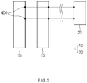
- FIG. 5 is a plan view illustrating a structure of a battery module according to the present invention.
- the battery module 1 may include a secondary battery 10.
- the secondary battery 10 may be provided in plurality, and descriptions of a structure of the secondary battery 10 will be cited from the above descriptions.
- the battery module 1 may include a control unit 20 receiving information with respect to a temperature of an exterior 200 (see FIG. 1 ) on areas on which temperature sensing units 300 (see FIG. 1 ) of the secondary batteries 10 are attached.
- the temperature sensing units mounted on the plurality of secondary batteries 10 sense the temperature of the exterior on the area to which the temperature sensing units are attached to transmit the sensed temperature information to the control unit 20. Thereafter, when a temperature on a portion of the areas to which the temperature sensing units attached to the plurality of secondary batteries 10 are attached exceeds a predetermined value, the control unit 20 may (i) interrupt current of the secondary batteries to which the temperature sensing units, which transmit information on the temperature that exceeds the predetermined value, are attached or may (ii) transmit a warning signal to the outside.
- a control method of the control unit in the battery module according to the present invention will be described in more detail as follows.
- the control unit 20 of the battery module 1 receives information on a temperature from each of the PTC element and the NTC element, which are provided in the temperature sensing unit of the secondary battery 10.
- control unit may determine whether the temperature provided from the NTC element (i) is equal to or less than a first reference temperature, (ii) is equal to or less than a second reference temperature that exceeds the first reference temperature and is greater than the first reference temperature, or (iii) exceeds the second reference temperature.
- control unit determines whether the temperature provided from the PTC element (i) is equal to or less than a third reference temperature or (ii) exceeds the third reference temperature.
- the control unit transmits a first warning signal to the outside. Thereafter, when it is determined that the temperature provided from the NTC element exceeds the second reference temperature, the control unit operates as follows according to the temperature provided from the PTC element of the temperature sensing unit provided with the NTC element.
- the control unit interrupts the current of the secondary battery provided with the temperature sensing unit including the NTC element and the PTC element.
- the control unit transmits a second warning signal to the outside.
- the second reference temperature and the third reference temperature may be the same as each other.
- the second reference temperature and the third reference temperature are the same as each other, since a temperature that serves as a reference for interrupting the current of the secondary battery is provided in a single, stable control and simplified control of the control unit may be enabled.
- the fact that the second reference temperature and the third reference temperature are 'the same' as each other means that the second reference temperature is not only numerically exactly the same as the third reference temperature, but also a difference between the second reference temperature and the third reference temperature is insignificant. Thus, it should be interpreted to include a case in which a person skilled in the art may determine that the two temperatures are substantially the same.
- the second reference temperature may be greater than the third reference temperature.
- an operation of the above-described control unit relates to a case in which information on the temperatures is provided from the temperature sensing unit including the PTC element and the NTC element.
- the control unit may operate as follows.
- the control unit may interrupt current of the secondary battery provided with the temperature sensing unit including the PTC element.
- the control unit may transmit a warning signal to the outside.
- the interruption may be performed permanently or temporarily.
- the permanent interruption of the current of the secondary battery may mean that the current is still interrupted even when the temperature of the secondary battery returns to a normal temperature.
- the current of the secondary battery is performed temporarily, it may mean that the current of the secondary battery flows again when the temperature of the secondary battery returns to the normal temperature.
- each of the plurality of secondary batteries constituting the battery module is provided with at least one temperature sensing unit provided with the PTC element and NTC element, the reliable of the control of the secondary battery may be improved based on the information on the temperature provided from the PTC element and the NTC element.
- a method for manufacturing a secondary battery according to the present invention may include an inner body part preparation step of preparing an inner body part 200b forming an inner body of a sheet-like exterior 200, a sensing unit disposition step of disposing a plurality of temperature sensing units 300 that sense a temperature of one area of the exterior 200 on the inner body part 200b, a circuit unit disposition step of disposing a circuit unit 350 that electrically connects the plurality of temperature sensing units 300 to each other on the inner body part 200b, and a film attachment step of attaching an insulating film 200a on the inner body part 200b of the exterior 200 so that the insulating film 200a is attached on the inner body part 200b to cover the plurality of temperature sensing units 300 while wrapping circumferences of the plurality of temperature sensing units 300.
- the circuit unit 350 may be disposed on the inner body part 200b of the exterior 200 in a deposition or printing manner. Also, the circuit unit disposition step may be performed after the sensing unit disposition step.
- the insulating film 200a may include a first insulating film 202a and a second insulating film 204a.
- the film attachment step of the method for manufacturing the secondary battery according to the present invention may include a first film attachment step which is performed before the sensing unit disposition step and the circuit unit disposition step and in which the first insulating film 202a having the through-hole is attached to the inner body part 200b of the exterior 200.
- the film attachment step may further include a second film attachment step which is performed after the sensing unit disposition step and the circuit unit disposition step and in which the second insulating film 204a is attached to a surface of an upper portion of the first insulating film 202a to cover the plurality of temperature sensing units 300 and the circuit unit 350.
- a through-hole may be formed in the first insulating film 202a.
- the plurality of temperature sensing units 300 may be disposed on an area of the surface of the inner body part 20b of the exterior 200, on which the first insulating film 202a is not attached in the first film attachment step (that is, an area in which the through-hole is formed).
- the circuit unit 350 may be disposed on the area of the surface of the inner body part 20b of the exterior 200, on which the first insulating film 202a is not attached in the first film attachment step (that is, the area in which the through-hole is formed).
- the first insulting film 202a may wrap the circumferences of the temperature sensing units 300 and the circuit unit 350.
Landscapes
- Chemical & Material Sciences (AREA)
- Chemical Kinetics & Catalysis (AREA)
- Electrochemistry (AREA)
- General Chemical & Material Sciences (AREA)
- Engineering & Computer Science (AREA)
- Manufacturing & Machinery (AREA)
- Microelectronics & Electronic Packaging (AREA)
- General Physics & Mathematics (AREA)
- Physics & Mathematics (AREA)
- Secondary Cells (AREA)
- Connection Of Batteries Or Terminals (AREA)
- Battery Mounting, Suspending (AREA)
- Sealing Battery Cases Or Jackets (AREA)
Applications Claiming Priority (2)
| Application Number | Priority Date | Filing Date | Title |
|---|---|---|---|
| KR1020190080175A KR102779080B1 (ko) | 2019-07-03 | 2019-07-03 | 이차전지, 그 이차전지의 제조방법 및 그 이차전지를 포함하는 전지모듈 |
| PCT/KR2020/008324 WO2021002635A1 (ko) | 2019-07-03 | 2020-06-26 | 이차전지, 그 이차전지의 제조방법 및 그 이차전지를 포함하는 전지모듈 |
Publications (2)
| Publication Number | Publication Date |
|---|---|
| EP3907812A1 true EP3907812A1 (de) | 2021-11-10 |
| EP3907812A4 EP3907812A4 (de) | 2022-03-30 |
Family
ID=74100901
Family Applications (1)
| Application Number | Title | Priority Date | Filing Date |
|---|---|---|---|
| EP20835100.7A Pending EP3907812A4 (de) | 2019-07-03 | 2020-06-26 | Sekundärbatterie, herstellungsverfahren für sekundärbatterie, und batteriemodul mit sekundärbatterie |
Country Status (6)
| Country | Link |
|---|---|
| US (1) | US12003001B2 (de) |
| EP (1) | EP3907812A4 (de) |
| JP (1) | JP7200382B2 (de) |
| KR (1) | KR102779080B1 (de) |
| CN (1) | CN113728511B (de) |
| WO (1) | WO2021002635A1 (de) |
Families Citing this family (5)
| Publication number | Priority date | Publication date | Assignee | Title |
|---|---|---|---|---|
| CN214505584U (zh) * | 2021-04-02 | 2021-10-26 | 泰科电子(上海)有限公司 | 电池包温度采集模块和系统 |
| KR20230071656A (ko) | 2021-11-16 | 2023-05-23 | 주식회사 엘지에너지솔루션 | 이차 전지 및 감지 시스템 |
| KR102790200B1 (ko) * | 2022-01-28 | 2025-04-03 | 주식회사 엘지에너지솔루션 | 온도 측정이 가능한 전지팩용 인쇄회로기판 및 그 제조방법 |
| JP2023150126A (ja) * | 2022-03-31 | 2023-10-16 | 本田技研工業株式会社 | 固体電池、保護システム及び保護方法 |
| KR20240011041A (ko) * | 2022-07-18 | 2024-01-25 | 주식회사 엘지에너지솔루션 | 온도센서, 그를 포함하는 이차전지 및 이차전지 제조방법 |
Family Cites Families (33)
| Publication number | Priority date | Publication date | Assignee | Title |
|---|---|---|---|---|
| JPS5786265U (de) | 1980-11-14 | 1982-05-27 | ||
| JPH08128901A (ja) * | 1994-10-31 | 1996-05-21 | Sanyo Electric Co Ltd | 温度センサーとパック電池 |
| JP3705079B2 (ja) | 2000-05-23 | 2005-10-12 | 株式会社村田製作所 | 二次電池パックの温度検知装置及び二次電池パック |
| JP4363092B2 (ja) | 2003-06-13 | 2009-11-11 | 日産自動車株式会社 | 組電池用電池セルユニット、電池セルユニットを用いた組電池および電池セルユニットの製造方法 |
| WO2006121067A1 (ja) | 2005-05-10 | 2006-11-16 | Matsushita Electric Industrial Co., Ltd. | 保護回路、及び電池パック |
| JP4886212B2 (ja) | 2005-05-11 | 2012-02-29 | パナソニック株式会社 | 保護回路 |
| KR20090098522A (ko) | 2008-03-14 | 2009-09-17 | 삼성에스디아이 주식회사 | 이차 전지 |
| JP2010073847A (ja) * | 2008-09-18 | 2010-04-02 | Sony Corp | Ptcサーミスタ素子及びその製造方法、並びに2次電池セル及びその製造方法 |
| KR101132166B1 (ko) * | 2008-10-14 | 2012-04-05 | 주식회사 엘지화학 | 제조 공정성이 향상된 이차전지 팩 및 ptc 소자 |
| US8794827B2 (en) | 2009-02-02 | 2014-08-05 | Yazaki Corporation | Thermal sensing structure and insulating structure of thermal sensing circuit |
| JP5303302B2 (ja) * | 2009-02-10 | 2013-10-02 | 矢崎総業株式会社 | 温度検出用回路体の絶縁構造 |
| JP2010244844A (ja) | 2009-04-06 | 2010-10-28 | Nec Energy Devices Ltd | 電池パック |
| DE102010026435B4 (de) | 2010-07-08 | 2023-01-26 | Vitesco Technologies Germany Gmbh | Vorrichtung zur Klassifizierung einer elektrischen Kontaktierung zwischen zwei Anschlusselementen |
| JP2012227983A (ja) | 2011-04-15 | 2012-11-15 | Konica Minolta Medical & Graphic Inc | 充電システム、電子機器および充電装置 |
| KR101907211B1 (ko) | 2012-01-03 | 2018-10-11 | 삼성에스디아이 주식회사 | 파우치형 배터리 |
| KR20130089376A (ko) * | 2012-02-02 | 2013-08-12 | 주식회사 엘지화학 | 온도 센서를 포함하는 이차전지 |
| JP5978718B2 (ja) | 2012-03-30 | 2016-08-24 | 三菱マテリアル株式会社 | 温度調節機能付き電池 |
| WO2014003085A1 (en) * | 2012-06-27 | 2014-01-03 | Semiconductor Energy Laboratory Co., Ltd. | Power storage unit and solar power generation unit |
| KR101287632B1 (ko) * | 2012-06-27 | 2013-07-24 | 세향산업 주식회사 | 리튬폴리머 전지용 리드 필름 가열 접착 장치 및 그 방법 |
| KR101631124B1 (ko) | 2012-11-13 | 2016-06-17 | 주식회사 엘지화학 | 온도 측정 부재를 포함하는 이차전지 |
| JP2014103055A (ja) | 2012-11-22 | 2014-06-05 | Nissan Motor Co Ltd | 電池パック |
| KR101577387B1 (ko) * | 2013-05-06 | 2015-12-16 | 주식회사 엘지화학 | 이차전지, 이를 포함하는 이차전지 모듈 및 이차전지 팩 |
| US9389279B2 (en) | 2013-10-02 | 2016-07-12 | Lg Chem, Ltd. | Battery cell assembly with a thin profile sensor |
| US9972869B2 (en) | 2014-01-31 | 2018-05-15 | Lg Chem, Ltd. | Battery cell assembly having improved thermal sensing capability |
| CN106133980B (zh) * | 2014-04-03 | 2019-03-08 | 株式会社村田制作所 | 二次电池、电池组、电子装置、电动车辆、电力存储装置及电力系统 |
| TWI509862B (zh) * | 2014-09-12 | 2015-11-21 | Polytronics Technology Corp | 二次電池 |
| KR101750488B1 (ko) | 2014-11-24 | 2017-06-23 | 주식회사 엘지화학 | 직렬 연결된 ptc 서미스터들을 포함하는 이상온도 센싱 어셈블리 및 이를 포함하는 전지팩 |
| KR102347801B1 (ko) | 2015-06-08 | 2022-01-07 | 에스케이온 주식회사 | 온도측정 소자를 포함한 이차 전지 |
| JP2017084647A (ja) | 2015-10-29 | 2017-05-18 | パナソニックIpマネジメント株式会社 | 電池システム |
| JP6612720B2 (ja) | 2016-11-28 | 2019-11-27 | 本田技研工業株式会社 | 二次電池 |
| KR101849763B1 (ko) | 2017-01-02 | 2018-04-17 | 세방전지(주) | 일체형 온도센서를 구비한 리튬 전지 |
| KR102357835B1 (ko) | 2017-01-26 | 2022-02-04 | 삼성에스디아이 주식회사 | 배터리 팩 |
| CN109425440A (zh) * | 2017-09-05 | 2019-03-05 | 力特有限公司 | 温度感测带 |
-
2019
- 2019-07-03 KR KR1020190080175A patent/KR102779080B1/ko active Active
-
2020
- 2020-06-26 US US17/424,386 patent/US12003001B2/en active Active
- 2020-06-26 WO PCT/KR2020/008324 patent/WO2021002635A1/ko not_active Ceased
- 2020-06-26 CN CN202080009583.8A patent/CN113728511B/zh active Active
- 2020-06-26 EP EP20835100.7A patent/EP3907812A4/de active Pending
- 2020-06-26 JP JP2021536824A patent/JP7200382B2/ja active Active
Also Published As
| Publication number | Publication date |
|---|---|
| CN113728511B (zh) | 2023-08-22 |
| JP2022515429A (ja) | 2022-02-18 |
| CN113728511A (zh) | 2021-11-30 |
| WO2021002635A1 (ko) | 2021-01-07 |
| EP3907812A4 (de) | 2022-03-30 |
| US12003001B2 (en) | 2024-06-04 |
| KR20210004179A (ko) | 2021-01-13 |
| JP7200382B2 (ja) | 2023-01-06 |
| US20220102822A1 (en) | 2022-03-31 |
| KR102779080B1 (ko) | 2025-03-11 |
Similar Documents
| Publication | Publication Date | Title |
|---|---|---|
| US12003001B2 (en) | Secondary battery, method for manufacturing the secondary battery, and battery module including the secondary battery | |
| US12469894B2 (en) | Secondary battery and battery module having the same | |
| US6444350B1 (en) | Battery unit which can detect an abnormal temperature rise of at least one of a plurality of cells | |
| EP2533326B1 (de) | Wiederaufladbare Batterie | |
| JP5401512B2 (ja) | 二次電池 | |
| EP2736092A1 (de) | Batteriepack | |
| EP2581959A2 (de) | Sekundärbatterie | |
| US8580424B2 (en) | Rechargeable battery | |
| US12051822B2 (en) | Secondary battery and battery pack including the same | |
| EP3723184B1 (de) | Batteriepack | |
| CN107871840B (zh) | 电池单元 | |
| KR20110088348A (ko) | 배터리 어셈블리 | |
| KR20120111267A (ko) | 배터리 팩 | |
| US11271275B2 (en) | Battery pack | |
| KR101147203B1 (ko) | 이차 전지 팩 및 그 제조 방법 | |
| JP4692030B2 (ja) | 電池用温度検出装置 | |
| US20220367967A1 (en) | Power storage module | |
| KR102234289B1 (ko) | 배터리 팩 | |
| EP4113734B1 (de) | Beutelförmige sekundärbatterie mit verbesserter sicherheit und batteriemodul damit | |
| CN121713310A (zh) | 能够检测电解液泄漏的电池单元及包括电池单元的电池模块 | |
| KR20170022176A (ko) | 이차전지 |
Legal Events
| Date | Code | Title | Description |
|---|---|---|---|
| STAA | Information on the status of an ep patent application or granted ep patent |
Free format text: STATUS: THE INTERNATIONAL PUBLICATION HAS BEEN MADE |
|
| PUAI | Public reference made under article 153(3) epc to a published international application that has entered the european phase |
Free format text: ORIGINAL CODE: 0009012 |
|
| STAA | Information on the status of an ep patent application or granted ep patent |
Free format text: STATUS: REQUEST FOR EXAMINATION WAS MADE |
|
| 17P | Request for examination filed |
Effective date: 20210806 |
|
| AK | Designated contracting states |
Kind code of ref document: A1 Designated state(s): AL AT BE BG CH CY CZ DE DK EE ES FI FR GB GR HR HU IE IS IT LI LT LU LV MC MK MT NL NO PL PT RO RS SE SI SK SM TR |
|
| A4 | Supplementary search report drawn up and despatched |
Effective date: 20220301 |
|
| RAP3 | Party data changed (applicant data changed or rights of an application transferred) |
Owner name: LG ENERGY SOLUTION, LTD. |
|
| RIC1 | Information provided on ipc code assigned before grant |
Ipc: H01M 50/581 20210101ALI20220223BHEP Ipc: H01M 50/124 20210101ALI20220223BHEP Ipc: H01M 50/116 20210101ALI20220223BHEP Ipc: H01M 50/105 20210101ALI20220223BHEP Ipc: H01M 50/10 20210101ALI20220223BHEP Ipc: H01M 10/42 20060101ALI20220223BHEP Ipc: H01M 50/572 20210101ALI20220223BHEP Ipc: H01M 10/48 20060101AFI20220223BHEP |
|
| DAV | Request for validation of the european patent (deleted) | ||
| DAX | Request for extension of the european patent (deleted) |