EP3908710B1 - Strangpressprofil - Google Patents
Strangpressprofil Download PDFInfo
- Publication number
- EP3908710B1 EP3908710B1 EP19836590.0A EP19836590A EP3908710B1 EP 3908710 B1 EP3908710 B1 EP 3908710B1 EP 19836590 A EP19836590 A EP 19836590A EP 3908710 B1 EP3908710 B1 EP 3908710B1
- Authority
- EP
- European Patent Office
- Prior art keywords
- arms
- cores
- junction elements
- profile
- bar according
- Prior art date
- Legal status (The legal status is an assumption and is not a legal conclusion. Google has not performed a legal analysis and makes no representation as to the accuracy of the status listed.)
- Active
Links
Images






Classifications
-
- E—FIXED CONSTRUCTIONS
- E04—BUILDING
- E04B—GENERAL BUILDING CONSTRUCTIONS; WALLS, e.g. PARTITIONS; ROOFS; FLOORS; CEILINGS; INSULATION OR OTHER PROTECTION OF BUILDINGS
- E04B1/00—Constructions in general; Structures which are not restricted either to walls, e.g. partitions, or floors or ceilings or roofs
- E04B1/38—Connections for building structures in general
- E04B1/58—Connections for building structures in general of bar-shaped building elements
- E04B1/5806—Connections for building structures in general of bar-shaped building elements with a cross-section having an open profile
-
- E—FIXED CONSTRUCTIONS
- E04—BUILDING
- E04C—STRUCTURAL ELEMENTS; BUILDING MATERIALS
- E04C3/00—Structural elongated elements designed for load-supporting
- E04C3/02—Joists; Girders, trusses, or trusslike structures, e.g. prefabricated; Lintels; Transoms; Braces
- E04C3/04—Joists; Girders, trusses, or trusslike structures, e.g. prefabricated; Lintels; Transoms; Braces of metal
- E04C3/06—Joists; Girders, trusses, or trusslike structures, e.g. prefabricated; Lintels; Transoms; Braces of metal with substantially solid, i.e. unapertured, web
-
- E—FIXED CONSTRUCTIONS
- E04—BUILDING
- E04C—STRUCTURAL ELEMENTS; BUILDING MATERIALS
- E04C3/00—Structural elongated elements designed for load-supporting
- E04C3/02—Joists; Girders, trusses, or trusslike structures, e.g. prefabricated; Lintels; Transoms; Braces
- E04C3/28—Joists; Girders, trusses, or trusslike structures, e.g. prefabricated; Lintels; Transoms; Braces of materials not covered by groups E04C3/04 - E04C3/20
-
- F—MECHANICAL ENGINEERING; LIGHTING; HEATING; WEAPONS; BLASTING
- F16—ENGINEERING ELEMENTS AND UNITS; GENERAL MEASURES FOR PRODUCING AND MAINTAINING EFFECTIVE FUNCTIONING OF MACHINES OR INSTALLATIONS; THERMAL INSULATION IN GENERAL
- F16B—DEVICES FOR FASTENING OR SECURING CONSTRUCTIONAL ELEMENTS OR MACHINE PARTS TOGETHER, e.g. NAILS, BOLTS, CIRCLIPS, CLAMPS, CLIPS OR WEDGES; JOINTS OR JOINTING
- F16B7/00—Connections of rods or tubes, e.g. of non-circular section, mutually, including resilient connections
- F16B7/18—Connections of rods or tubes, e.g. of non-circular section, mutually, including resilient connections using screw-thread elements
- F16B7/185—Connections of rods or tubes, e.g. of non-circular section, mutually, including resilient connections using screw-thread elements with a node element
-
- F—MECHANICAL ENGINEERING; LIGHTING; HEATING; WEAPONS; BLASTING
- F16—ENGINEERING ELEMENTS AND UNITS; GENERAL MEASURES FOR PRODUCING AND MAINTAINING EFFECTIVE FUNCTIONING OF MACHINES OR INSTALLATIONS; THERMAL INSULATION IN GENERAL
- F16B—DEVICES FOR FASTENING OR SECURING CONSTRUCTIONAL ELEMENTS OR MACHINE PARTS TOGETHER, e.g. NAILS, BOLTS, CIRCLIPS, CLAMPS, CLIPS OR WEDGES; JOINTS OR JOINTING
- F16B7/00—Connections of rods or tubes, e.g. of non-circular section, mutually, including resilient connections
- F16B7/18—Connections of rods or tubes, e.g. of non-circular section, mutually, including resilient connections using screw-thread elements
- F16B7/187—Connections of rods or tubes, e.g. of non-circular section, mutually, including resilient connections using screw-thread elements with sliding nuts or other additional connecting members for joining profiles provided with grooves or channels
-
- E—FIXED CONSTRUCTIONS
- E04—BUILDING
- E04B—GENERAL BUILDING CONSTRUCTIONS; WALLS, e.g. PARTITIONS; ROOFS; FLOORS; CEILINGS; INSULATION OR OTHER PROTECTION OF BUILDINGS
- E04B1/00—Constructions in general; Structures which are not restricted either to walls, e.g. partitions, or floors or ceilings or roofs
- E04B1/38—Connections for building structures in general
- E04B1/58—Connections for building structures in general of bar-shaped building elements
- E04B1/5825—Connections for building structures in general of bar-shaped building elements with a closed cross-section
-
- E—FIXED CONSTRUCTIONS
- E04—BUILDING
- E04C—STRUCTURAL ELEMENTS; BUILDING MATERIALS
- E04C3/00—Structural elongated elements designed for load-supporting
- E04C3/02—Joists; Girders, trusses, or trusslike structures, e.g. prefabricated; Lintels; Transoms; Braces
- E04C3/04—Joists; Girders, trusses, or trusslike structures, e.g. prefabricated; Lintels; Transoms; Braces of metal
- E04C2003/0404—Joists; Girders, trusses, or trusslike structures, e.g. prefabricated; Lintels; Transoms; Braces of metal beams, girders, or joists characterised by cross-sectional aspects
- E04C2003/0426—Joists; Girders, trusses, or trusslike structures, e.g. prefabricated; Lintels; Transoms; Braces of metal beams, girders, or joists characterised by cross-sectional aspects characterised by material distribution in cross section
- E04C2003/0439—Joists; Girders, trusses, or trusslike structures, e.g. prefabricated; Lintels; Transoms; Braces of metal beams, girders, or joists characterised by cross-sectional aspects characterised by material distribution in cross section the cross-section comprising open parts and hollow parts
-
- E—FIXED CONSTRUCTIONS
- E04—BUILDING
- E04C—STRUCTURAL ELEMENTS; BUILDING MATERIALS
- E04C3/00—Structural elongated elements designed for load-supporting
- E04C3/02—Joists; Girders, trusses, or trusslike structures, e.g. prefabricated; Lintels; Transoms; Braces
- E04C3/04—Joists; Girders, trusses, or trusslike structures, e.g. prefabricated; Lintels; Transoms; Braces of metal
- E04C2003/0404—Joists; Girders, trusses, or trusslike structures, e.g. prefabricated; Lintels; Transoms; Braces of metal beams, girders, or joists characterised by cross-sectional aspects
- E04C2003/0443—Joists; Girders, trusses, or trusslike structures, e.g. prefabricated; Lintels; Transoms; Braces of metal beams, girders, or joists characterised by cross-sectional aspects characterised by substantial shape of the cross-section
- E04C2003/0447—Joists; Girders, trusses, or trusslike structures, e.g. prefabricated; Lintels; Transoms; Braces of metal beams, girders, or joists characterised by cross-sectional aspects characterised by substantial shape of the cross-section circular- or oval-shaped
-
- E—FIXED CONSTRUCTIONS
- E04—BUILDING
- E04C—STRUCTURAL ELEMENTS; BUILDING MATERIALS
- E04C3/00—Structural elongated elements designed for load-supporting
- E04C3/02—Joists; Girders, trusses, or trusslike structures, e.g. prefabricated; Lintels; Transoms; Braces
- E04C3/04—Joists; Girders, trusses, or trusslike structures, e.g. prefabricated; Lintels; Transoms; Braces of metal
- E04C2003/0404—Joists; Girders, trusses, or trusslike structures, e.g. prefabricated; Lintels; Transoms; Braces of metal beams, girders, or joists characterised by cross-sectional aspects
- E04C2003/0443—Joists; Girders, trusses, or trusslike structures, e.g. prefabricated; Lintels; Transoms; Braces of metal beams, girders, or joists characterised by cross-sectional aspects characterised by substantial shape of the cross-section
- E04C2003/0465—Joists; Girders, trusses, or trusslike structures, e.g. prefabricated; Lintels; Transoms; Braces of metal beams, girders, or joists characterised by cross-sectional aspects characterised by substantial shape of the cross-section square- or rectangular-shaped
-
- E—FIXED CONSTRUCTIONS
- E04—BUILDING
- E04C—STRUCTURAL ELEMENTS; BUILDING MATERIALS
- E04C3/00—Structural elongated elements designed for load-supporting
- E04C3/02—Joists; Girders, trusses, or trusslike structures, e.g. prefabricated; Lintels; Transoms; Braces
- E04C3/04—Joists; Girders, trusses, or trusslike structures, e.g. prefabricated; Lintels; Transoms; Braces of metal
- E04C2003/0404—Joists; Girders, trusses, or trusslike structures, e.g. prefabricated; Lintels; Transoms; Braces of metal beams, girders, or joists characterised by cross-sectional aspects
- E04C2003/0443—Joists; Girders, trusses, or trusslike structures, e.g. prefabricated; Lintels; Transoms; Braces of metal beams, girders, or joists characterised by cross-sectional aspects characterised by substantial shape of the cross-section
- E04C2003/0469—Joists; Girders, trusses, or trusslike structures, e.g. prefabricated; Lintels; Transoms; Braces of metal beams, girders, or joists characterised by cross-sectional aspects characterised by substantial shape of the cross-section triangular-shaped
-
- E—FIXED CONSTRUCTIONS
- E04—BUILDING
- E04C—STRUCTURAL ELEMENTS; BUILDING MATERIALS
- E04C3/00—Structural elongated elements designed for load-supporting
- E04C3/02—Joists; Girders, trusses, or trusslike structures, e.g. prefabricated; Lintels; Transoms; Braces
- E04C3/04—Joists; Girders, trusses, or trusslike structures, e.g. prefabricated; Lintels; Transoms; Braces of metal
- E04C2003/0404—Joists; Girders, trusses, or trusslike structures, e.g. prefabricated; Lintels; Transoms; Braces of metal beams, girders, or joists characterised by cross-sectional aspects
- E04C2003/0443—Joists; Girders, trusses, or trusslike structures, e.g. prefabricated; Lintels; Transoms; Braces of metal beams, girders, or joists characterised by cross-sectional aspects characterised by substantial shape of the cross-section
- E04C2003/0478—X-shaped
Definitions
- the present invention relates to a structural bar of the type as recited in the preamble of the first claim.
- the present invention relates to a structural bar of the type suitable for use in the construction of frames or modular structures in which a plurality of extruded profiles are positioned and connected in an ordinate manner.
- extrusion is an industrial production process of plastic deformation allowing the production of objects with a constant cross-section, such as pipes, bars, sections and sheets. It is used for metal materials, such as steel, aluminium, lead or copper, plastics, such as rubber or thermoplastics, and in general for materials with a high degree of plasticity.
- extruded profiles can be simply L or T-shaped or have much more complex shapes. Profiles of this type can be used to make frames for window frames or other frames predisposed for the construction of structures subject to loads or otherwise.
- extruded profiles used for structural purposes have a basic quadrangular shape, typically describing a square perimeter.
- the locking nuts which are usually inserted by sliding into the lateral interstices, must be inserted beforehand as none of the profiles described allows insertion after the profile has been closed at the ends, for example with interface portions.
- the extruded profile has a cross section wherein the arms include T-shaped elements with side chamfers.
- This profile also has significant drawbacks.
- the nuts must be inserted in advance inside the section defined by the profile.
- the interface elements must be modified and made differently depending on the type of connection desired, for example in the case in which the interface element is the junction of a structure where three or four bars meet, compared to an angular joint.
- the profile itself although of different shape, works by compression like all conventional profiles and, therefore, is always normally coupled to the other profiles.
- the technical purpose of the present invention is to devise an extruded profile able to substantially overcome at least some of the drawbacks mentioned.
- one important aim of the invention is to obtain an extruded profile that allows different types of couplings to be made, compared to known profiles, in such a way as to distribute the loads in a different way.
- Another important aim of the invention is to create a profile that allows the coupling nuts to be inserted even when the extruded profile is connected to the ends and it is no longer possible to fit the sliding nuts inside the side slots of the profile.
- the measures, values, shapes, and geometric references when associated with words like “about” or other similar terms such as “approximately” or “substantially”, are to be understood as except for measurement errors or inaccuracies owing to production and/or manufacturing errors and, above all, except for a slight divergence from the value, measure, shape, or geometric reference with which it is associated.
- said terms, if associated with a value preferably indicate a divergence of not more than 10% of said value.
- reference numeral 1 globally denotes the extruded profile according to the invention.
- the profile 1 is for the construction of real structural bars and/or frames, comprising a plurality of structural bars and/or frames.
- the structural bars provide for the assembly of the profile 1 with joining means for extruded profiles.
- the profile 1 is coupled to a joining device for extruded profiles 100, as described below.
- the profile 1 defines a surface with a normal section 10.
- the normal section surface 10 is therefore the area described by the profile 1.
- the extruded profile 1 is substantially a beam having a prevailing extension axis and the sections of which, normal to the prevailing extension axis, identify said profile or, in particular, the normal section surface 10.
- the prevailing extension axis may be straight or curved.
- the profile 1 creates the beam when extruded along its prevailing extension axis.
- extruded profile 1 is understood to means that the profile is geometrically extruded, it is therefore a profile, and the term extrusion has, in this meaning, no reference to the type of processing.
- extruded profiles 1 of this type are, however, commonly obtained by industrial extrusion methods or by other methods such as, for example, pultrusion or yet others.
- the profile 1 defines then a horizontal load direction 1a and a vertical load direction 1b.
- the horizontal 1a and vertical load directions 1b create with the prevailing extension axis a substantially ordered triple.
- the three directions may identify the barycentric axes of the extruded profile 1, or at least part of it.
- the load directions 1a, 1b preferably define the directions along which, in use, the stresses to which the extruded profile is subjected in the plane defined by the normal section surface 10 lie.
- the extruded profile 1 may be subject, in use, to other loads such as, for example, typically eulerian normal loads, i.e. tip loads oriented integrally with the prevailing extension axis, or other loads.
- the loads themselves may subject the entire extruded profile 1, or the structural bar made with it, to derived stresses, e.g. flexural stresses, or others yet.
- the horizontal load direction 1a lies along the normal section surface 10
- the vertical load direction1b lies along the normal section surface 10 perpendicular to the horizontal load direction 1a.
- the profile 1 is therefore described below in two-dimensional terms, i.e. referring to what is defined along the plane of the normal section surface 10.
- the profile 1 includes a core 2 and a plurality of arms 3.
- the core 2 is arranged in a central position at the intersection of the directions 1a, 1b. Substantially, it defines the centre or fulcrum of the profile 1.
- the core 2 may be of various shapes and sizes. Preferably, the core 2 is a regular shape, for example substantially square.
- substantially referring to geometric shapes, hereinafter shall be taken to mean that the shape is not strictly and precisely as described, but that it defines roughly a similar shape. This, therefore, does not prevent the corners from being rounded or the sides from, for example, presenting curved, slightly curved or serrated portions.
- the arms 3 are connected to the core 2 starting from at least part of the vertices of the square shape. Even more preferably, but not necessarily, the arms 3 are four in number and each connected to a vertex of the square in such a way as to complete all the vertices.
- the core 2 may also comprise a connection hole 20.
- connection hole 20 is preferably arranged at the centre of the profile 1 and, therefore, at the meeting point of the load axes 1a, 1b.
- connection hole 20 is preferably suitable to allow the connection with other elements.
- connection hole 20 is, in particular, suitable to allow the connection of the profile 1 and of the device 100 in such a way as to create a structural bar.
- connection hole 20 preferably includes internal threaded portions so that at least one screw can be trapped.
- the core 2 may, therefore, be in one piece with the arms 3, and preferably it is, or it can be separate from them, as long as it can be conveniently attached to them, so that the profile 1 can be easily created.
- Each of the arms 3 includes a radial segment 30 and a tangential segment 31.
- the radial segment 30 is preferably a section of the normal section surface 10 extending along a prevailing direction of its own, for example straight and possibly curved.
- the radial segment 30 is also radially connected to the core 2.
- the radial segment 30 can be connected in specific points of the core 2 if the core is a regular shape, for example square.
- the tangential segment 31 is, instead, connected perpendicularly to the radial segment 30. More in detail, preferably, the tangential segment 31 is connected to the free end of the radial segment 30.
- the tangential segment 31, like the radial segment 30 is preferably a section of the normal section surface 10 extending along a prevailing direction of its own, for example straight, and possibly curved.
- It may therefore be the same size as the radial segment 30, or it may also be different lengths.
- the tangential segment 31 can be connected to the radial segment 30 at a midpoint thereof, for example the midpoint creating a substantially T-shape especially if segments 30, 31 are straight, or at an end.
- the segments 30, 31 can also be in one piece or can be connectable to make the arms 3.
- the segments 30, 31 may have a regular or substantially rectangular shape, as shown in Fig. 1 and Figs. 6-8 , or they may have substantially pointed ends, for example at right angles, as shown in Figs. 2-5 .
- the segments 30, 31 are rectangular in shape.
- the shape of the substantially rectangular segments 30, 31 should not be understood in the literal restrictive sense, but may be taken to mean a predominantly rectangular shape in which, however, some edges may also be chamfered or rounded.
- the radial segments 30 of the adjacent arms 3 are preferably perpendicular to each other.
- the adjacent arms 3 are the arms 3 arranged adjacent or proximal to each other around the core 2.
- the arms 3 have the above characteristic, but not all the adjacent arms 3 need to be absolutely perpendicular to each other.
- the two facing arms which could potentially be considered adjacent in the absence of the fourth arm 3, need not be and are not perpendicular to each other.
- the adjacent arms 3 are the arms 3 that can be reasonably considered, in a structural sense, as the actually contiguous and subsequent arms 3.
- the radial segments 30 are each oriented at 45° with respect to the horizontal load direction 1a and/or the vertical load direction 1b. Consequently, the tangential segments 31 of the adjacent arms 3 are configured to simultaneously support the same load C along the horizontal load direction 1a and/or the vertical load direction 1b.
- the load C is preferably a single load oriented along the horizontal load direction 1a and/or the vertical load direction 1b.
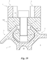
- a load C could consist, for example, of a device 100 resting on the tangential segments 31 or an internal structural bar resting on segments 31 of the profile, as shown in Figs. 16-21 .
- the tangential segments 31 distribute the stress resulting from the load C preferably tangentially or, in structural terms, shear.
- the profile 1 can be made in different forms.
- the profile 1 preferably comprises a core 2 and four arms 3.
- each of the arms 3 creates a T-structure by means of the radial 30 and tangential 31 segments.
- the profile 1 creates a normal section surface 10 the perimeter of which is substantially octagonal and defined by alternate tangential 31 and empty segments.
- Each empty segment is, preferably, identified by the rectilinear conjunction of two ends respectively facing each other of adjacent tangential segments 31.
- the profile 1 may also comprise a plurality of cores 2.
- the profile 1 preferably also comprises junction elements 4.
- junction elements 4 preferably connect two separate arms 3 each connected to a separate core 2.
- the junction elements 4 connect the arms 3 starting from their respective ends spaced from the cores 2.
- junction elements 4 can be portions of normal section surface 10 extending along their own prevailing direction, for example straight and possibly curved.
- the cores 2 and the junction elements 4 are two in number and the arms 3 are four in number for each of the cores 2.
- junction elements 4 and arms 3 in particular those interconnected via junction elements 4, define a separator 5.
- the separator 5 is substantially a closed portion of the normal section surface 10.
- the separator 5 is arranged between the cores 2 and defines a substantially hexagonal shape.
- the adjacent arms 3 and the portion of the core 2 between the adjacent arms 3, i.e. included therein, preferably define a substantially octagonal shape accessible at the empty segment defined between the arms 3.
- the cores 2 are three in number and aligned along the same direction. Consequently, the junction elements 4 are four in number and the arms 3 are four in number for each of the cores 2.
- junction elements 4 and arms 3 interconnected via junction elements 4, define two separators 5.
- both are arranged between the cores 2 and define a substantially hexagonal shape.
- the adjacent arms 3 and the portion of the core 2 between the adjacent arms 3, i.e. included therein preferably define a substantially octagonal shape accessible at the empty segment defined between the arms 3.
- the configuration of the profile 1 is conceptually similar to the third embodiment with the difference that the three cores 2 are arranged in an L instead of being aligned.
- the separators 5 are therefore preferably in contact with each other, while the other characteristics have already been described and are in any case visible in Fig. 4 .
- the cores 2 are four in number and are arranged in a square.
- the junction elements 4 are four in number and the arms 3 are three in number for each of the cores 2.
- the cores 2, junction elements 4 and arms 3 are interconnected via junction elements 4, so as define a single separator 5.
- junction elements 4 are delimited by the cores 2, junction elements 4 and arms 3 interconnected by junction elements 4 defining a substantially octagonal shape.
- the fifth embodiment could also be made in an alternative configuration, as shown in fig. 6 .
- the cores 2 are four in number and arranged in a square
- the junction elements 4 are eight in number
- the arms 3 are four in number for each of the cores 2.
- junction elements 4 and arms 3 interconnected via junction elements 4, define four separators 5.
- junction elements 4 in turn create a central separator 5.
- the cores 2 are six in number and are arranged in a rectangle.
- junction elements 4 are therefore fourteen in number and the arms 3 are four in number for each of the cores 2.
- junction elements 4 and arms 3, interconnected via junction elements 4, define seven separators 5.
- junction elements 4 four by four, create two central separators 5.
- the device 100 comprises at least one support 101 and teeth 102.
- the support 101 is substantially a plate suitable to be arranged in adhesion to one end of an extruded profile and preferably to the profile 1.
- the support 101 therefore, defines a connection surface 11.
- connection surface 11 is flat and is suitable to allow interfacing with an extruded profile.
- connection surface 11 thus also defines a second horizontal load direction 11a and a second vertical load direction 11b.
- the second horizontal load direction 11a is arranged along the connection surface 11.
- the second vertical load direction 11b is also arranged along the connection surface 11 and is perpendicular to the second horizontal load direction 11a.
- the second directions 11a and 11b define a centre for the connection surface 11.
- the second directions 11a and 11b may coincide with the barycentric axes of the device 100, or with the barycentric axes of part of it.
- the device 100 comprises, as mentioned, a plurality of teeth 102. The latter protrude from the support 101 preferably perpendicularly to the connection surface 11.
- the teeth 102 and part of the support 101 create at least two grooves 200.
- the grooves 200 are preferably cavities delimited by the teeth 102 and by the support 101, which therefore assume a modelled shape compared to the teeth 102 and to the support 101.
- the grooves 200 are convex. In addition, they extend along the second horizontal load direction 11a and the second vertical load direction 11b respectively. Substantially, therefore, the second load directions 11a and 11b define the directions with respect to which the connection is defined.
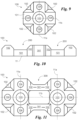
- the grooves 200 each define a section perpendicular to the connection surface 11 of a trapezoidal shape diverging from the support 101 outwards, as shown in figs. 10 and 19 .
- the teeth 102 may, for example, define a substantially truncated pyramidal shape with a triangular base.
- the support 101 can be modelled into various shapes, for example, compatible with the extruded profiles for which it is intended.
- the teeth 102 are arranged at non-adjacent sides of the octagonal shape so that the grooves 200 made by the teeth 102 and by the support 101 intersect perpendicularly, as shown in Fig. 9 .
- the grooves 200 intersect in such a way that the cross is substantially centred with respect to the intersection of the second load directions 11a, 11b.
- the device 100 comprises a plurality of supports 101.
- the supports 101 could be two in number. However, they may also be in greater numbers, as shown in figs. 12-15 .
- the supports 101 are mutually connected by means of an extension 300.
- the extension 300 may be a plate suitable to connect the support 101 or other connection elements, known in the prior art, suitable to connect the parts at a distance.
- the extension 300 comprises at least two connectors 301.
- the connectors 301 are preferably suitable to connect two teeth 102 each arranged on a different support 101. Substantially, the connectors 301 are, for the device 100, conceptually similar to the joining elements 4 of the profile 1.
- the connectors 301 can, in fact, be superposed on the said joining elements 4.
- the device 100 comprises a connection opening 103.
- connection opening 103 is preferably arranged in the centre of the support 101, consequently, it is preferably arranged at the intersection of the second directions 11a, 11b.
- connection opening 103 is suitable to allow the connection of the device 100 to other external elements.
- the external elements may be extruded profiles of any shape and, preferably, the profile 1.
- connection opening 103 is, preferably, a threaded hole into which a screw can be inserted.
- connection opening 103 could also be of a size compatible with the connection hole 20.
- the device 100 and the profile 1 are connected to each other in such a way as to create a structural bar.
- the device 100 and the extruded profile 1 are connected to each other in such a way that the normal section surface 10 and the connection surface 11 are opposite each other and the horizontal 1a and vertical 1b load directions are respectively aligned with the second horizontal 11a and vertical 11b load directions.
- the profile 1 and the device 100 are connected by conventional means of attachment, such as screws, which are partially arranged inside the connection hole 20 and the connection opening 103 and compatible therewith.
- the design of the device 100 makes it possible to use a device 100 with single support 101 also for profiles 1 according to multi-core 2 embodiments.
- a structural bar for example, it is possible to make a structural bar, according to the invention, either with a device 100 with double support 101, shown in figs. 10-11 , and a double core profile 2, shown in Fig. 2 , or with two single support devices 100, shown in Fig. 9 , mounted on the double core 2 profile 1 in such a way that the supports 101 are respectively centred with the cores 2.
- the device 100 lastly, also includes at least one coupling cavity 104 for each of the grooves 200.
- the coupling cavity 104 may have the same characteristics as the connection hole 20 and/or the connection opening 103.
- the coupling cavity 104 is, in fact, suitable to allow the connection of the device with external elements.
- the coupling cavity 104 is arranged in a decentralized position inside the device 100 and preferably in proximity of the outer perimeter thereof.
- the nut 400 may be a conventional nut, known in the prior art, and already used in the industry to connect profiles to joining elements.
- the nut 400 is, in this case, available inside the space between adjacent arms 3 which substantially form a guide for the nut 400.
- the arms 3 and core 2 define an octagonal shape
- the nut 400 may also be octagonal or, in any case, be compatible with the shape of the cavity.
- the nut 400 may thus be in one piece, as known, or it may assume an advantageous configuration.
- the nut 400 can, in fact, preferably be disassembled and includes a locking base 401 and a locking cover 402.
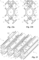
- the locking base 401 is preferably the portion of the nut suitable to adhere to the core 2 of the profile 1. Consequently, preferably, the locking base 401 is substantially at least counter-shaped to the portion of profile 1 defined by the radial segments 30 of two adjacent arms 3 and to the portion of core 2 enclosed by said radial segments 30, as shown in Fig. 22a .
- the locking cover 402 is instead preferably suitable to adhere to at least part of the tangential segments 31 of the adjacent arms 3 of the profile, as shown in Fig. 22b , and is accessible from the empty segment of the profile 1.
- the locking base 401 and the cover 402 are two complementary elements configured to make the nut 400. They are at least mutually counter-shaped, but they may also be interlocking elements.
- the nut 400 has a substantially octagonal profile and therefore the locking base 401 and the locking cover 402 define profiles that are fragments of the octagonal profile of the assembled nut 400.
- the locking cover 402 includes two straight sections arranged along the perimeter portion of the octagonal profile and extending at two adjacent sides of the octagon.
- the locking base 401 corresponds to the remaining portion of the profile. In this way, it is possible to insert the nuts 400 inside the guide defined by the adjacent arms 3 of the profiles 1 even when the extruded profiles 1 are not accessible from their ends, for example because they are assembled on both sides with joining devices 100 to create a structural bar.
- the procedure for the insertion of the nuts 400 envisages a first insertion phase, a second insertion phase and an assembly phase. These phases are highlighted, in sequence, in Fig. 23 .
- the locking base 401 is inserted askew between two adjacent arms 3 so that it can pass through the empty segment.
- the locking base 401 once placed in the guide, is rested on the core 2 so that it is substantially counter-shaped to the radial segments 30 and the portion of the core included therein.
- the locking cover 402 is inserted in the guide made by said adjacent arms 3 but spaced from the locking base 401 along the prevailing extension axis of the extruded profile 1.
- the locking cover 402 is also inserted askew and then straightened so that it is counter-shaped to at least part of the tangential segments 31 of the adjacent arms 3.
- the locking cover 402 is made to slide on the locking base 401 in such a way as to form a real nut 400.
- the locking base 401 and the locking cover 402 are secured using the locking screws used for coupling with another profile 1.
- the invention also makes it possible to make frames.
- a frame is understood as a structure inside which the profiles 1 are ordinate and mutually connected by means of devices 100.
- the frame includes at least one structural bar and an extruded profile 1 wherein the tangential segments 31 of the adjacent arms 3 create a substantially trapezoidal shape counter-shaped to the groove 200.
- the extruded profile 1 is arranged in contact with the device 100 of the structural bar so that the tangential segments 31 rest on the teeth 102.
- the extruded profile 1 and the structural bar are secured to each other by conventional coupling means, e.g. screws, which are partially arranged inside the coupling cavity 104 and connected to the nut 400.
- the coupling cavity(ies) 104 are configured in such a way that each allows access to the space and to the spaces between the adjacent arms 3 of the profile 1. In this way, access to the cavities 104 can be performed using the guides defined by the adjacent arms 3 inside the extruded profile 1 wherein, inside each, the nut 400 can be housed.
- the coupling cavity 104 faces the space between two adjacent arms 3.
- the nut 400 may therefore also conventionally have a hole for the arrangement of the screw inside it.
- the invention comprises a new use of an extruded profile 1 defining a normal section surface 10 and a substantially octagonal perimeter defined by tangential segments 31 and alternating empty segments to support at least a load C.
- the novelty of use lies in the fact that the profile 1 is used in such a way that the load C is oriented perpendicularly to at least one of the empty segments.
- This new method of use allows the shear load to be transmitted and differs from all profiles of the prior art that work under normal or perpendicular loads to the tangential segments 31.
- the profile 1 according to the invention achieves important advantages.
- the extruded profile 1 allows different types of couplings to be made, compared to known profiles, and loads to be distributed differently, as has been pointed out several times.
- a further advantage of profile 1 is that it is easy to machine and to make.
- a further advantage is that the geometrical conformation of the profile 1, and in particular of the arms 3, makes it possible to create octagonal cavities between adjacent arms 3 such that the nuts can be inserted starting from the empty segment.
- the shape of the guide made by the profiles 1 allows the nuts 400 or other compatible nuts to be inserted, even when the profile 1 has been connected to a device 100, for example to make a structural bar and thus a connection.
- the device 100 could be in one piece and/or part of the profile 1 itself.
- the teeth 102 may correspond to portions of arms 3 cut in such a way that the core forms the support 101.
Landscapes
- Engineering & Computer Science (AREA)
- Architecture (AREA)
- General Engineering & Computer Science (AREA)
- Civil Engineering (AREA)
- Structural Engineering (AREA)
- Mechanical Engineering (AREA)
- Physics & Mathematics (AREA)
- Electromagnetism (AREA)
- Bridges Or Land Bridges (AREA)
- Mutual Connection Of Rods And Tubes (AREA)
- Extrusion Moulding Of Plastics Or The Like (AREA)
Claims (13)
- Strukturstange umfassend:- ein extrudiertes Profil (1), das eine normale Schnittfläche (10) definiert, eine horizontale Belastungsrichtung (1a) entlang der normalen Schnittfläche (10) und eine vertikale Belastungsrichtung (1b) entlang der normalen Schnittfläche (10), die senkrecht zur horizontalen Belastungsrichtung (1a) steht, wobei das Profil (1) umfasst:- einen Kern (2), der in einer Zentralposition an der Kreuzung dieser Richtungen (1a, 1b) angeordnet ist,- eine Mehrzahl von Armen (3), die jeweils umfassen:- ein Radialsegment (30), das radial mit dem Kern (2) verbunden ist und zueinander senkrecht steht und jeweils um 45° zur horizontalen Belastungsrichtung (1a) und/oder zur vertikalen Belastungsrichtung (1b) orientiert ist, und- ein Tangentialsegment (31), das senkrecht mit dem Radialsegment (30) verbunden ist und so konfiguriert ist, bei Ausübung einer einzigen Belastung (C) auf das extrudierte Profil (1) entlang der horizontalen Belastungsrichtung (1a) und/oder der vertikalen Belastungsrichtung (1b), gleichzeitig die Belastung (C) gemeinsam zu tragen, um die aus der Belastung (C) resultierende Beanspruchung als Scherbeanspruchung zu verteilen;- eine Verbindungsvorrichtung (100) für extrudierte Profile umfassend eine Stütze (101), die eine flache Verbindungsfläche (11) definiert, die geeignet ist, den Kontakt mit dem extrudierten Profil (1) zu ermöglichen, eine zweite horizontale Belastungsrichtung (11a) entlang der Verbindungsfläche (11) und eine zweite vertikale Belastungsrichtung (11b) entlang der Verbindungsfläche (11), die senkrecht zur zweiten horizontalen Belastungsrichtung (11a) steht, wobei die Vorrichtung (100) eine Mehrzahl von Zähnen (102) umfasst, die senkrecht zur Verbindungsfläche (11) von der Stütze (101) hervorstehen;und dadurch gekennzeichnet, dass:- die Zähne (102) mit Teil der Stütze (101) mindestens zwei konvexe Nuten (200) bilden, die sich jeweils entlang der zweiten horizontalen Belastungsrichtung (11a) und entlang der zweiten vertikalen Belastungsrichtung (11b) erstrecken,- die Vorrichtung (100) und das extrudierte Profil (1) so miteinander verbunden sind, dass die normale Schnittfläche (10) und die Verbindungsfläche (11) einander gegenüberliegen und die horizontale Belastungsrichtung (1a) und die vertikale (1b) Belastungsrichtung jeweils mit den zweiten horizontalen (11a) und vertikalen (11b) Belastungsrichtungen ausgerichtet sind.
- Strukturstange nach Anspruch 1 umfassend vier der Arme (3) und wobei jeder der Arme (3) eine T-Struktur mittels des radialen (30) und des tangentialen (31) Segments bildet.
- Strukturstange nach Anspruch 1 umfassend eine Mehrzahl der Kerne (2) und eine Mehrzahl von Verbindungselementen (4), die zwei verschiedene Arme (3) verbinden, die jeweils mit einem unterschiedlichen Kern (2) verbunden sind, beginnend von ihren jeweiligen Enden, die von den Kernen (2) beabstandet sind.
- Strukturstange nach Anspruch 3, wobei die Kerne (2) und die Verbindungselemente (4) jeweils zwei an der Zahl sind und die Arme (3) vier an der Zahl für jeden der Kerne (2) sind, wobei die Kerne (2), die Verbindungselemente (4) und die Arme (3), die durch die Verbindungselemente (4) verbunden sind, ein Trennelement (5) definieren, das zwischen den Kernen (2) angeordnet ist und eine im Wesentlichen sechseckige Form definiert.
- Strukturstange nach Anspruch 3, wobei die Kerne (2) drei an der Zahl sind und entlang derselben Richtung ausgerichtet sind, die Verbindungselemente (4) vier an der Zahl sind und die Arme (3) vier an der Zahl für jeden der Kerne (2) sind, wobei die Kerne (2), die Verbindungselemente (4) und die Arme (3), die durch die Verbindungselemente (4) verbunden sind, zwei Trennelemente (5) definieren, die zwischen den Kernen (2) angeordnet sind und eine im Wesentlichen sechseckige Form definieren.
- Strukturstange nach Anspruch 3, wobei die Kerne (2) drei an der Zahl sind und in einer L-Form (Figur 4) angeordnet sind, die Verbindungselemente (4) vier an der Zahl sind und die Arme (3) vier an der Zahl für jeden der Kerne (2) sind, wobei die Kerne (2), die Verbindungselemente (4) und die Arme (3), die durch die Verbindungselemente (4) verbunden sind, zwei Trennelemente (5) definieren, die zwischen den Kernen (2) angeordnet sind und eine im Wesentlichen sechseckige Form definieren.
- Strukturstange nach Anspruch 3, wobei die Kerne (2) vier an der Zahl sind und in einem Quadrat (Figur 5) angeordnet sind, die Verbindungselemente (4) vier an der Zahl sind und die Arme (3) drei an der Zahl für jeden der Kerne (2) sind, wobei die Kerne (2), die Verbindungselemente (4) und die Arme (3), die durch die Verbindungselemente (4) verbunden sind, ein Trennelement (5) definieren, der durch die Kerne (2), die Verbindungselemente (4) und die Arme (3), die durch die Verbindungselemente (4) verbunden sind, begrenzt wird und eine im Wesentlichen achteckige Form definiert.
- Strukturstange nach mindestens Anspruch 1, wobei der Kern (2) eine im Wesentlichen quadratische Form definiert, die Arme (3) mit dem Kern (2), beginnend von mindestens einem Teil der Eckpunkte der quadratischen Form, verbunden sind und der Kern (2) eine Verbindungsbohrung (20) umfasst, die geeignet ist, die Verbindung mit anderen Elementen zu ermöglichen.
- Strukturstange nach mindestens Anspruch 1, wobei die angrenzenden Arme (3) und der Abschnitt des Kerns (2) zwischen den angrenzenden Armen (3) eine im Wesentlichen achteckige Form definieren, die für das leere zwischen den Armen (3) definierte Segment zugänglich ist.
- Strukturstange nach Anspruch 1, wobei jede der Nuten (200) einen Schnitt definiert, der senkrecht zur Verbindungsfläche (11) mit einer trapezförmigen Form steht, die von der Stütze (101) nach außen abweicht.
- Strukturstange nach mindestens einem vorhergehenden Anspruch, wobei die Stütze (101) eine achteckige Form entlang der Verbindungsfläche (11) definiert und die Zähne (102) an nicht benachbarten Seiten der achteckigen Form angeordnet sind, so dass die Nuten (200), die durch die Zähne (102) und die Stütze (101) gebildet werden, sich senkrecht kreuzen.
- Strukturstange nach mindestens Anspruch 1 umfassend eine Mehrzahl der Stützen (101), wobei die Stützen (101) durch eine Verlängerung (300) miteinander verbunden sind, wobei die Verlängerung (300) mindestens zwei Verbinder (301) umfasst, die geeignet sind, zwei Zähne (102) zu verbinden, die jeweils auf einer unterschiedlichen Stütze (101) angeordnet sind.
- Strukturstange nach mindestens Anspruch 1 umfassend mindestens eine Verbindungsöffnung (103), die sich in der Mitte der Stütze (101) befindet und geeignet ist, die Verbindung zwischen der Vorrichtung (100) und dem extrudierten Profil (1) zu ermöglichen.
Applications Claiming Priority (2)
| Application Number | Priority Date | Filing Date | Title |
|---|---|---|---|
| IT102019000000127A IT201900000127A1 (it) | 2019-01-07 | 2019-01-07 | Profilo estruso |
| PCT/IB2019/061212 WO2020144523A1 (en) | 2019-01-07 | 2019-12-20 | An extruded profile |
Publications (3)
| Publication Number | Publication Date |
|---|---|
| EP3908710A1 EP3908710A1 (de) | 2021-11-17 |
| EP3908710C0 EP3908710C0 (de) | 2024-07-24 |
| EP3908710B1 true EP3908710B1 (de) | 2024-07-24 |
Family
ID=66166362
Family Applications (1)
| Application Number | Title | Priority Date | Filing Date |
|---|---|---|---|
| EP19836590.0A Active EP3908710B1 (de) | 2019-01-07 | 2019-12-20 | Strangpressprofil |
Country Status (5)
| Country | Link |
|---|---|
| US (1) | US12060711B2 (de) |
| EP (1) | EP3908710B1 (de) |
| ES (1) | ES2989417T3 (de) |
| IT (1) | IT201900000127A1 (de) |
| WO (1) | WO2020144523A1 (de) |
Families Citing this family (5)
| Publication number | Priority date | Publication date | Assignee | Title |
|---|---|---|---|---|
| DE102019115548A1 (de) * | 2019-05-07 | 2020-11-12 | Carl Zeiss Fixture Systems Gmbh | Profilstrang für die Errichtung von Trägervorrichtungen |
| US11629495B2 (en) * | 2020-09-18 | 2023-04-18 | Wei-Jan Lin | Modular framing structure design and a method of using the same |
| IT202100007130A1 (it) | 2021-03-24 | 2022-09-24 | Cerloj Ema | Struttura componibile e procedimento di realizzazione di detta struttura componibile |
| DE102022212544A1 (de) * | 2022-11-24 | 2024-05-29 | Robert Bosch Gesellschaft mit beschränkter Haftung | Trennwand mit zweiteiligen Säulen |
| US20240336308A1 (en) * | 2023-04-04 | 2024-10-10 | Sterling Petersen | Load bearing vehicle attachment series |
Citations (3)
| Publication number | Priority date | Publication date | Assignee | Title |
|---|---|---|---|---|
| US4017199A (en) * | 1974-12-09 | 1977-04-12 | Syma Intercontinental S.A. | Elastically-deformed adjustable T-joint |
| US4583359A (en) * | 1983-11-25 | 1986-04-22 | Octanorm-Vertriebs-Gesellschaft Mit Beschrankter Haftung Fur Bauelemente | Profile tubes for the production of readily assembled and dismantled structures |
| DE10156220C1 (de) * | 2001-11-15 | 2003-05-08 | Domo Architektursysteme Logist | Profilträgersystem, insbesondere für den Messe- und Ausstellungsbau |
Family Cites Families (45)
| Publication number | Priority date | Publication date | Assignee | Title |
|---|---|---|---|---|
| GB1497068A (en) * | 1974-11-29 | 1978-01-05 | Sharp & Law Ltd | Support systems |
| DK146578C (da) * | 1980-04-02 | 1984-04-24 | Voss Unical As | Byggesaet til fremstilling af et panel, f.eks. et skilt |
| DE3128595C2 (de) * | 1981-07-20 | 1990-12-06 | Gebrüder Vieler GmbH, 5860 Iserlohn | Gestell aus lösbar verbindbaren Profilstangen |
| US4544300A (en) * | 1983-04-07 | 1985-10-01 | Lew Hyok S | Slide connectors with locking means |
| DE9006344U1 (de) * | 1990-06-05 | 1990-09-06 | Bahr, Frank, 4952 Porta Westfalica | Vorrichtung zum lösbaren Verbinden von zwei Profilstäben |
| DE9100099U1 (de) * | 1991-01-07 | 1991-06-13 | Bahr, Frank, 4952 Porta Westfalica | Durch Schrauben mit einem Profilstab verbundener Tragstab |
| US5263296A (en) * | 1991-07-17 | 1993-11-23 | Speral Aluminium Inc. | Modular scaffolding assembly |
| DE9200645U1 (de) * | 1992-01-21 | 1992-04-16 | Festo KG, 7300 Esslingen | Profilteil |
| US5429438A (en) * | 1993-07-12 | 1995-07-04 | 80/20 Inc. | Mechanical structure and guide block |
| JPH08159119A (ja) * | 1994-12-07 | 1996-06-18 | N I Shi Auto Tec Kk | 連結材 |
| US5647650A (en) * | 1995-04-21 | 1997-07-15 | Metro Industries, Inc. | Modular storage and support assembly |
| DE19520892A1 (de) * | 1995-06-08 | 1996-12-12 | Heron Sondermaschinen Und Steu | Plattenverbinder |
| DE19815474A1 (de) * | 1998-04-07 | 1999-10-21 | Bosch Gmbh Robert | Lineareinheit mit einer Gleitführung für einen Schlitten |
| US6712543B1 (en) * | 1999-07-21 | 2004-03-30 | Fms Forder-Und Montage-Systeme Schmalzhofer Gmbh | Connecting device for profiled bars with grooves |
| EP1259738B1 (de) * | 2000-01-28 | 2004-03-24 | FMS Förder- und Montage-Systeme Schmalzhofer GmbH | Profilverbindungseinrichtung |
| FI108571B (fi) | 2000-03-02 | 2002-02-15 | Fennotek Oy | Profiilikiskojärjestelmä |
| DE10012729B4 (de) * | 2000-03-16 | 2007-06-14 | Kahl, Helmuth, Dipl.-Ing. | Vorrichtung zum stirnseitigen Verbinden von Profilstäben |
| JP3484150B2 (ja) * | 2000-09-06 | 2004-01-06 | スガツネ工業株式会社 | 直交状角材の連結固定装置 |
| US6682255B2 (en) * | 2000-10-05 | 2004-01-27 | Universal Display & Fixtures Company | Modular merchandising display connector |
| DE20102661U1 (de) * | 2001-02-15 | 2001-04-05 | FMS Förder- und Montage-Systeme Schmalzhofer GmbH, 75031 Eppingen | Schlittensystem für einen Profilstab |
| TW521801U (en) * | 2001-08-23 | 2003-02-21 | Yu-An Liu | Jointing device for partitioning system |
| CA2371667A1 (en) * | 2002-02-14 | 2003-08-14 | Taylor Manufacturing Industries Inc. | Connecting device for modular frame construction |
| DE20210133U1 (de) * | 2002-07-01 | 2003-11-13 | Bosch Rexroth AG, 70173 Stuttgart | Verbindung von Profilstreben |
| DE50308743D1 (de) * | 2002-09-23 | 2008-01-17 | Winfried K W Holscher | Verbindungseinrichtung für zwei werkstücke, insbesondere für strangartige hohlprofile |
| EP1706652B1 (de) * | 2004-01-22 | 2008-03-26 | Winfried K. W. Holscher | Anschlussverbindungsanordnung für zwei strangartige hohlprofile |
| SK286964B6 (sk) * | 2004-05-17 | 2009-08-06 | Peter Čupka | Priestorový konštrukčný systém zložený z modulových spojovacích prvkov |
| DE202004012544U1 (de) * | 2004-05-18 | 2004-11-25 | Band, Richard | Verbindersystem |
| ITBS20040144A1 (it) * | 2004-12-01 | 2005-03-01 | Gimatic Spa | Profilato multivalente per la composizione di telai, supporti, strutture portanti e simili |
| US20060236640A1 (en) * | 2005-03-15 | 2006-10-26 | Hung Si C | Structural framework having solid coupling |
| US7762023B2 (en) * | 2006-06-11 | 2010-07-27 | Tayco Panelink Ltd | Mounting system for workstations |
| CA2616623C (en) * | 2007-01-03 | 2012-04-03 | Skyline Displays, Inc. | Multi-configurable tubular display system |
| DE102008006439B4 (de) | 2008-01-28 | 2015-05-21 | Alfer Aluminium Gesellschaft Mbh | Bausatz aus Konstruktionsprofil, Profilverbinder und Tragarmen |
| CN201386480Y (zh) | 2009-03-13 | 2010-01-20 | 程玉秋 | 门窗格条连接件 |
| GB2472199B (en) * | 2009-07-27 | 2013-05-08 | Barco Nv | Spacer plate and support structure |
| EP2564074B1 (de) * | 2010-04-26 | 2020-09-09 | Blanking Systems, Inc. | Eckteil zur mechanischen verbindung von rahmenelementen |
| EP2786026B1 (de) | 2011-11-30 | 2015-10-14 | Hartmut Flaig | Profilstab, profilverbund sowie verfahren zum herstellen eines profilverbundes |
| CN102518930A (zh) | 2011-12-19 | 2012-06-27 | 安徽巨一自动化装备有限公司 | 一种铝型材 |
| DE202012007790U1 (de) * | 2012-08-15 | 2012-11-15 | Wolfgang Rixen | Befestigungssystem |
| DE202014102037U1 (de) * | 2014-04-30 | 2015-07-31 | Hartmut Flaig | Profilverbinder sowie Profilverbund |
| DE202014104524U1 (de) * | 2014-09-22 | 2016-01-05 | Hartmut Flaig | Profilstab sowie Profilverbindung |
| CA3000755C (en) * | 2015-10-07 | 2024-02-20 | Blanking Systems, Inc. | Three-sided corner assembly |
| US10648496B2 (en) * | 2017-06-28 | 2020-05-12 | Blanking Systems, Inc. | Mount |
| DE102017006233A1 (de) * | 2017-07-03 | 2019-01-03 | Wolfgang Rixen | Befestigungsanordnung |
| US10662650B2 (en) * | 2017-10-31 | 2020-05-26 | Vention Inc. | T-slot extrusion structure |
| CN108131553A (zh) * | 2018-01-15 | 2018-06-08 | 江门市蓬江区欧罗富五金橡胶制品有限公司 | 负重梁 |
-
2019
- 2019-01-07 IT IT102019000000127A patent/IT201900000127A1/it unknown
- 2019-12-20 US US17/420,765 patent/US12060711B2/en active Active
- 2019-12-20 WO PCT/IB2019/061212 patent/WO2020144523A1/en not_active Ceased
- 2019-12-20 ES ES19836590T patent/ES2989417T3/es active Active
- 2019-12-20 EP EP19836590.0A patent/EP3908710B1/de active Active
Patent Citations (3)
| Publication number | Priority date | Publication date | Assignee | Title |
|---|---|---|---|---|
| US4017199A (en) * | 1974-12-09 | 1977-04-12 | Syma Intercontinental S.A. | Elastically-deformed adjustable T-joint |
| US4583359A (en) * | 1983-11-25 | 1986-04-22 | Octanorm-Vertriebs-Gesellschaft Mit Beschrankter Haftung Fur Bauelemente | Profile tubes for the production of readily assembled and dismantled structures |
| DE10156220C1 (de) * | 2001-11-15 | 2003-05-08 | Domo Architektursysteme Logist | Profilträgersystem, insbesondere für den Messe- und Ausstellungsbau |
Also Published As
| Publication number | Publication date |
|---|---|
| EP3908710C0 (de) | 2024-07-24 |
| WO2020144523A1 (en) | 2020-07-16 |
| US12060711B2 (en) | 2024-08-13 |
| ES2989417T3 (es) | 2024-11-26 |
| IT201900000127A1 (it) | 2020-07-07 |
| US20220112717A1 (en) | 2022-04-14 |
| EP3908710A1 (de) | 2021-11-17 |
Similar Documents
| Publication | Publication Date | Title |
|---|---|---|
| EP3908710B1 (de) | Strangpressprofil | |
| US7264416B2 (en) | Hollow chamber profile system for precision superstructures | |
| EP2766616B1 (de) | Mechanisch ineinandergreifende rahmenkonstruktionen | |
| EP2649328B1 (de) | Verriegelungsvorrichtung und verfahren zur befestigung von bauteilen an rohren | |
| US5304086A (en) | Toy construction element | |
| US4208850A (en) | Connector for knock-down cabinet | |
| US6068533A (en) | Panel element for multi-part construction toy | |
| US4785673A (en) | Strain-gauge sensor for measuring forces | |
| KR20140002778U (ko) | 분할 너트 압축 패스너 시스템 | |
| US10581232B2 (en) | Universal ring and plate assembly for electrical box | |
| JP6802351B2 (ja) | 蒸気タービン及びセンターガイドピン | |
| US4684282A (en) | Structural element for three dimensional objects, e.g. furniture | |
| KR20200127830A (ko) | 무용접 방식으로 트러스를 연결하는 브라켓 | |
| EP3138975B1 (de) | Kit zum stellen von wänden | |
| EP1149957A2 (de) | System von Profilstäben | |
| IT201900000124A1 (it) | Dispositivo di connessione per profili estrusi | |
| US12540469B2 (en) | Modular structure and making process of said modular structure | |
| CN215564090U (zh) | 一种副龙骨卡套 | |
| CN210255250U (zh) | 一种铣四方槽工装 | |
| CN212078663U (zh) | 一种型材及模板构造 | |
| EP4647733A1 (de) | Wägezelle | |
| KR101877907B1 (ko) | 다축 연결용 조인트 | |
| CN103321295A (zh) | 多功能快速组合连接系统及其生产方法 | |
| CN1357101A (zh) | 水准仪 | |
| JP5850820B2 (ja) | 螺旋構造体及びその製造方法 |
Legal Events
| Date | Code | Title | Description |
|---|---|---|---|
| STAA | Information on the status of an ep patent application or granted ep patent |
Free format text: STATUS: UNKNOWN |
|
| STAA | Information on the status of an ep patent application or granted ep patent |
Free format text: STATUS: THE INTERNATIONAL PUBLICATION HAS BEEN MADE |
|
| PUAI | Public reference made under article 153(3) epc to a published international application that has entered the european phase |
Free format text: ORIGINAL CODE: 0009012 |
|
| STAA | Information on the status of an ep patent application or granted ep patent |
Free format text: STATUS: REQUEST FOR EXAMINATION WAS MADE |
|
| 17P | Request for examination filed |
Effective date: 20210707 |
|
| AK | Designated contracting states |
Kind code of ref document: A1 Designated state(s): AL AT BE BG CH CY CZ DE DK EE ES FI FR GB GR HR HU IE IS IT LI LT LU LV MC MK MT NL NO PL PT RO RS SE SI SK SM TR |
|
| DAV | Request for validation of the european patent (deleted) | ||
| DAX | Request for extension of the european patent (deleted) | ||
| STAA | Information on the status of an ep patent application or granted ep patent |
Free format text: STATUS: EXAMINATION IS IN PROGRESS |
|
| 17Q | First examination report despatched |
Effective date: 20230414 |
|
| GRAP | Despatch of communication of intention to grant a patent |
Free format text: ORIGINAL CODE: EPIDOSNIGR1 |
|
| STAA | Information on the status of an ep patent application or granted ep patent |
Free format text: STATUS: GRANT OF PATENT IS INTENDED |
|
| INTG | Intention to grant announced |
Effective date: 20240216 |
|
| RAP1 | Party data changed (applicant data changed or rights of an application transferred) |
Owner name: ALUESSE SH.P.K. |
|
| GRAS | Grant fee paid |
Free format text: ORIGINAL CODE: EPIDOSNIGR3 |
|
| GRAA | (expected) grant |
Free format text: ORIGINAL CODE: 0009210 |
|
| STAA | Information on the status of an ep patent application or granted ep patent |
Free format text: STATUS: THE PATENT HAS BEEN GRANTED |
|
| AK | Designated contracting states |
Kind code of ref document: B1 Designated state(s): AL AT BE BG CH CY CZ DE DK EE ES FI FR GB GR HR HU IE IS IT LI LT LU LV MC MK MT NL NO PL PT RO RS SE SI SK SM TR |
|
| REG | Reference to a national code |
Ref country code: GB Ref legal event code: FG4D |
|
| REG | Reference to a national code |
Ref country code: CH Ref legal event code: EP |
|
| REG | Reference to a national code |
Ref country code: DE Ref legal event code: R096 Ref document number: 602019055845 Country of ref document: DE |
|
| REG | Reference to a national code |
Ref country code: IE Ref legal event code: FG4D |
|
| U01 | Request for unitary effect filed |
Effective date: 20240813 |
|
| U07 | Unitary effect registered |
Designated state(s): AT BE BG DE DK EE FI FR IT LT LU LV MT NL PT RO SE SI Effective date: 20240902 |
|
| RAP4 | Party data changed (patent owner data changed or rights of a patent transferred) |
Owner name: ALUESSE SH.P.K. |
|
| U1H | Name or address of the proprietor changed after the registration of the unitary effect |
Owner name: ALUESSE SH.P.K.; AL |
|
| U20 | Renewal fee for the european patent with unitary effect paid |
Year of fee payment: 6 Effective date: 20241017 |
|
| REG | Reference to a national code |
Ref country code: ES Ref legal event code: FG2A Ref document number: 2989417 Country of ref document: ES Kind code of ref document: T3 Effective date: 20241126 |
|
| REG | Reference to a national code |
Ref country code: GR Ref legal event code: EP Ref document number: 20240402407 Country of ref document: GR Effective date: 20241111 |
|
| PG25 | Lapsed in a contracting state [announced via postgrant information from national office to epo] |
Ref country code: NO Free format text: LAPSE BECAUSE OF FAILURE TO SUBMIT A TRANSLATION OF THE DESCRIPTION OR TO PAY THE FEE WITHIN THE PRESCRIBED TIME-LIMIT Effective date: 20241024 |
|
| PG25 | Lapsed in a contracting state [announced via postgrant information from national office to epo] |
Ref country code: PL Free format text: LAPSE BECAUSE OF FAILURE TO SUBMIT A TRANSLATION OF THE DESCRIPTION OR TO PAY THE FEE WITHIN THE PRESCRIBED TIME-LIMIT Effective date: 20240724 |
|
| PG25 | Lapsed in a contracting state [announced via postgrant information from national office to epo] |
Ref country code: IS Free format text: LAPSE BECAUSE OF FAILURE TO SUBMIT A TRANSLATION OF THE DESCRIPTION OR TO PAY THE FEE WITHIN THE PRESCRIBED TIME-LIMIT Effective date: 20241124 |
|
| PG25 | Lapsed in a contracting state [announced via postgrant information from national office to epo] |
Ref country code: HR Free format text: LAPSE BECAUSE OF FAILURE TO SUBMIT A TRANSLATION OF THE DESCRIPTION OR TO PAY THE FEE WITHIN THE PRESCRIBED TIME-LIMIT Effective date: 20240724 |
|
| PG25 | Lapsed in a contracting state [announced via postgrant information from national office to epo] |
Ref country code: RS Free format text: LAPSE BECAUSE OF FAILURE TO SUBMIT A TRANSLATION OF THE DESCRIPTION OR TO PAY THE FEE WITHIN THE PRESCRIBED TIME-LIMIT Effective date: 20241024 |
|
| PG25 | Lapsed in a contracting state [announced via postgrant information from national office to epo] |
Ref country code: RS Free format text: LAPSE BECAUSE OF FAILURE TO SUBMIT A TRANSLATION OF THE DESCRIPTION OR TO PAY THE FEE WITHIN THE PRESCRIBED TIME-LIMIT Effective date: 20241024 Ref country code: PL Free format text: LAPSE BECAUSE OF FAILURE TO SUBMIT A TRANSLATION OF THE DESCRIPTION OR TO PAY THE FEE WITHIN THE PRESCRIBED TIME-LIMIT Effective date: 20240724 Ref country code: NO Free format text: LAPSE BECAUSE OF FAILURE TO SUBMIT A TRANSLATION OF THE DESCRIPTION OR TO PAY THE FEE WITHIN THE PRESCRIBED TIME-LIMIT Effective date: 20241024 Ref country code: IS Free format text: LAPSE BECAUSE OF FAILURE TO SUBMIT A TRANSLATION OF THE DESCRIPTION OR TO PAY THE FEE WITHIN THE PRESCRIBED TIME-LIMIT Effective date: 20241124 Ref country code: HR Free format text: LAPSE BECAUSE OF FAILURE TO SUBMIT A TRANSLATION OF THE DESCRIPTION OR TO PAY THE FEE WITHIN THE PRESCRIBED TIME-LIMIT Effective date: 20240724 |
|
| PG25 | Lapsed in a contracting state [announced via postgrant information from national office to epo] |
Ref country code: SM Free format text: LAPSE BECAUSE OF FAILURE TO SUBMIT A TRANSLATION OF THE DESCRIPTION OR TO PAY THE FEE WITHIN THE PRESCRIBED TIME-LIMIT Effective date: 20240724 |
|
| PG25 | Lapsed in a contracting state [announced via postgrant information from national office to epo] |
Ref country code: CZ Free format text: LAPSE BECAUSE OF FAILURE TO SUBMIT A TRANSLATION OF THE DESCRIPTION OR TO PAY THE FEE WITHIN THE PRESCRIBED TIME-LIMIT Effective date: 20240724 |
|
| PG25 | Lapsed in a contracting state [announced via postgrant information from national office to epo] |
Ref country code: SK Free format text: LAPSE BECAUSE OF FAILURE TO SUBMIT A TRANSLATION OF THE DESCRIPTION OR TO PAY THE FEE WITHIN THE PRESCRIBED TIME-LIMIT Effective date: 20240724 |
|
| PLBE | No opposition filed within time limit |
Free format text: ORIGINAL CODE: 0009261 |
|
| STAA | Information on the status of an ep patent application or granted ep patent |
Free format text: STATUS: NO OPPOSITION FILED WITHIN TIME LIMIT |
|
| 26N | No opposition filed |
Effective date: 20250425 |
|
| U20 | Renewal fee for the european patent with unitary effect paid |
Year of fee payment: 7 Effective date: 20251118 |
|
| REG | Reference to a national code |
Ref country code: CH Ref legal event code: U11 Free format text: ST27 STATUS EVENT CODE: U-0-0-U10-U11 (AS PROVIDED BY THE NATIONAL OFFICE) Effective date: 20260101 |
|
| PGFP | Annual fee paid to national office [announced via postgrant information from national office to epo] |
Ref country code: GB Payment date: 20251218 Year of fee payment: 7 |
|
| PGFP | Annual fee paid to national office [announced via postgrant information from national office to epo] |
Ref country code: MC Payment date: 20251217 Year of fee payment: 7 |
|
| PGFP | Annual fee paid to national office [announced via postgrant information from national office to epo] |
Ref country code: TR Payment date: 20251216 Year of fee payment: 7 Ref country code: GR Payment date: 20251215 Year of fee payment: 7 |
|
| PGFP | Annual fee paid to national office [announced via postgrant information from national office to epo] |
Ref country code: IE Payment date: 20251218 Year of fee payment: 7 |
|
| PGFP | Annual fee paid to national office [announced via postgrant information from national office to epo] |
Ref country code: ES Payment date: 20260119 Year of fee payment: 7 |
|
| PGFP | Annual fee paid to national office [announced via postgrant information from national office to epo] |
Ref country code: CH Payment date: 20260101 Year of fee payment: 7 |