EP3908744B1 - Coque de pale de rotor, pale de rotor et éolienne - Google Patents
Coque de pale de rotor, pale de rotor et éolienne Download PDFInfo
- Publication number
- EP3908744B1 EP3908744B1 EP19831674.7A EP19831674A EP3908744B1 EP 3908744 B1 EP3908744 B1 EP 3908744B1 EP 19831674 A EP19831674 A EP 19831674A EP 3908744 B1 EP3908744 B1 EP 3908744B1
- Authority
- EP
- European Patent Office
- Prior art keywords
- rotor blade
- shell
- longitudinal direction
- layer
- tip
- Prior art date
- Legal status (The legal status is an assumption and is not a legal conclusion. Google has not performed a legal analysis and makes no representation as to the accuracy of the status listed.)
- Active
Links
Images


Classifications
-
- F—MECHANICAL ENGINEERING; LIGHTING; HEATING; WEAPONS; BLASTING
- F03—MACHINES OR ENGINES FOR LIQUIDS; WIND, SPRING, OR WEIGHT MOTORS; PRODUCING MECHANICAL POWER OR A REACTIVE PROPULSIVE THRUST, NOT OTHERWISE PROVIDED FOR
- F03D—WIND MOTORS
- F03D1/00—Wind motors with rotation axis substantially parallel to the air flow entering the rotor
- F03D1/06—Rotors
- F03D1/065—Rotors characterised by their construction elements
- F03D1/0675—Rotors characterised by their construction elements of the blades
-
- B—PERFORMING OPERATIONS; TRANSPORTING
- B29—WORKING OF PLASTICS; WORKING OF SUBSTANCES IN A PLASTIC STATE IN GENERAL
- B29D—PRODUCING PARTICULAR ARTICLES FROM PLASTICS OR FROM SUBSTANCES IN A PLASTIC STATE
- B29D99/00—Subject matter not provided for in other groups of this subclass
- B29D99/001—Producing wall or panel-like structures, e.g. for hulls, fuselages, or buildings
- B29D99/0021—Producing wall or panel-like structures, e.g. for hulls, fuselages, or buildings provided with plain or filled structures, e.g. cores, placed between two or more plates or sheets, e.g. in a matrix
-
- B—PERFORMING OPERATIONS; TRANSPORTING
- B29—WORKING OF PLASTICS; WORKING OF SUBSTANCES IN A PLASTIC STATE IN GENERAL
- B29D—PRODUCING PARTICULAR ARTICLES FROM PLASTICS OR FROM SUBSTANCES IN A PLASTIC STATE
- B29D99/00—Subject matter not provided for in other groups of this subclass
- B29D99/0025—Producing blades or the like, e.g. blades for turbines, propellers, or wings
- B29D99/0028—Producing blades or the like, e.g. blades for turbines, propellers, or wings hollow blades
-
- F—MECHANICAL ENGINEERING; LIGHTING; HEATING; WEAPONS; BLASTING
- F05—INDEXING SCHEMES RELATING TO ENGINES OR PUMPS IN VARIOUS SUBCLASSES OF CLASSES F01-F04
- F05B—INDEXING SCHEME RELATING TO WIND, SPRING, WEIGHT, INERTIA OR LIKE MOTORS, TO MACHINES OR ENGINES FOR LIQUIDS COVERED BY SUBCLASSES F03B, F03D AND F03G
- F05B2240/00—Components
- F05B2240/20—Rotors
- F05B2240/30—Characteristics of rotor blades, i.e. of any element transforming dynamic fluid energy to or from rotational energy and being attached to a rotor
- F05B2240/301—Cross-section characteristics
-
- F—MECHANICAL ENGINEERING; LIGHTING; HEATING; WEAPONS; BLASTING
- F05—INDEXING SCHEMES RELATING TO ENGINES OR PUMPS IN VARIOUS SUBCLASSES OF CLASSES F01-F04
- F05B—INDEXING SCHEME RELATING TO WIND, SPRING, WEIGHT, INERTIA OR LIKE MOTORS, TO MACHINES OR ENGINES FOR LIQUIDS COVERED BY SUBCLASSES F03B, F03D AND F03G
- F05B2250/00—Geometry
- F05B2250/70—Shape
- F05B2250/71—Shape curved
-
- F—MECHANICAL ENGINEERING; LIGHTING; HEATING; WEAPONS; BLASTING
- F05—INDEXING SCHEMES RELATING TO ENGINES OR PUMPS IN VARIOUS SUBCLASSES OF CLASSES F01-F04
- F05B—INDEXING SCHEME RELATING TO WIND, SPRING, WEIGHT, INERTIA OR LIKE MOTORS, TO MACHINES OR ENGINES FOR LIQUIDS COVERED BY SUBCLASSES F03B, F03D AND F03G
- F05B2280/00—Materials; Properties thereof
- F05B2280/60—Properties or characteristics given to material by treatment or manufacturing
- F05B2280/6003—Composites; e.g. fibre-reinforced
-
- Y—GENERAL TAGGING OF NEW TECHNOLOGICAL DEVELOPMENTS; GENERAL TAGGING OF CROSS-SECTIONAL TECHNOLOGIES SPANNING OVER SEVERAL SECTIONS OF THE IPC; TECHNICAL SUBJECTS COVERED BY FORMER USPC CROSS-REFERENCE ART COLLECTIONS [XRACs] AND DIGESTS
- Y02—TECHNOLOGIES OR APPLICATIONS FOR MITIGATION OR ADAPTATION AGAINST CLIMATE CHANGE
- Y02E—REDUCTION OF GREENHOUSE GAS [GHG] EMISSIONS, RELATED TO ENERGY GENERATION, TRANSMISSION OR DISTRIBUTION
- Y02E10/00—Energy generation through renewable energy sources
- Y02E10/70—Wind energy
- Y02E10/72—Wind turbines with rotation axis in wind direction
Definitions
- the invention relates to a rotor blade shell for a rotor blade of a wind power plant, a rotor blade for a wind power plant with at least one such rotor blade shell and a wind power plant with such a rotor blade.
- Rotor blades for wind turbines are often assembled from two rotor blade shells that are manufactured separately from one another.
- the two rotor blade shells are glued to one another in the region of the so-called leading edge or nose and the so-called trailing edge.
- one or more belts can be provided inside the rotor blade or the rotor blade shells, which essentially run along a longitudinal axis of the rotor blade from the rotor blade root to the rotor blade tip and impart additional stability or influence elastic properties of the rotor blade.
- such belts can ensure sufficient rigidity of the rotor blade in the direction of flapping and pivoting.
- US2010/296941A1 discloses a wind turbine rotor blade and is considered a relevant example of prior art.
- the rotor blade shell for a rotor blade of a wind turbine extends from a shell root in a longitudinal direction to a shell tip and from a shell trailing edge in a transverse direction, which can also be referred to as profile depth or profile direction, to a shell front edge.
- a longitudinally extending layer system of the rotor blade shell includes at least one core layer and two laminates disposed on opposite sides of the core layer. In this case, part of the core layer is formed in a first section of the rotor blade shell by a rotor blade belt running in the longitudinal direction one end of the first section facing the tip of the shell.
- At least one of the two laminates has at least one fiber layer in a second section of the rotor blade shell, which adjoins the first section at the end of the first section facing the shell tip and runs essentially up to the shell tip.
- This fiber layer extends in the transverse direction from the rear edge of the shell to the front edge of the shell and contains fibers, of which a major part, preferably more than 60%, in particular more than 80%, extends in the longitudinal direction.
- a rotor blade for a wind turbine has at least one rotor blade shell according to the first aspect of the invention.
- a wind power installation has at least one rotor blade according to the second aspect of the invention.
- Preferred aspects of the invention are based on the approach of providing a rotor blade shell with a rotor blade belt which does not extend over substantially the entire length of a rotor blade shell, i.e. in a longitudinal direction from an area at a shell root to an area at a shell tip, but only in a first section that is shorter in relation to the overall length.
- At least one fiber layer is arranged in a second section, which adjoins an end of the first section facing the shell tip , which extends in a transverse direction from a trailing edge of the rotor blade shell to a leading edge of the rotor blade shell and whose fibers are predominantly aligned along the longitudinal direction of the rotor blade shell.
- This orientation of the fibers allows the necessary rigidity to be achieved in the flapping and pivoting direction in the area of the tip of the rotor blade shell or the corresponding rotor blade.
- the at least one fiber layer can act as a belt replacement in the second section.
- the shape of the rotor blade shell or of the rotor blade containing the rotor blade shell can thus be freely selected in the area of the tip.
- the so-called threading axis of the rotor blade in the area of the tip in the direction of the trailing edge is curved or the rotor blade has a so-called arrow shape in the area of the tip, with the front and rear edges being curved in the longitudinal direction in such a way that a rotor blade crest, which is due to the progression of the maximum overall height of the cross-sectional profile of the rotor blade shell or the rotor blade in the longitudinal direction is defined, has a continuously increasing distance from the so-called pitch axis towards the blade tip, about which the rotor blade can be rotated during operation to set an angle of attack.
- the rotor blade belt in the first section which is shortened in comparison to the overall length of the rotor blade shell, e.g. by 10% or more, preferably by 20% or more, in particular by 40% or more, and the at least one fiber layer in the second section can be part of a layer system that extends in the longitudinal direction.
- the rotor blade belt is preferably contained in a core layer that is bordered by two laminates on opposite sides, in particular in a thickness direction perpendicular to the longitudinal and transverse direction, in which the overall height of the rotor blade shell or the corresponding rotor blade is defined.
- at least one of the two laminates contains the at least one fiber layer, which predominantly has fibers in the longitudinal direction of the rotor blade.
- the laminates preferably also contain one or more fiber composite materials or fiber composite layers, e.g. glass fiber fabrics and/or fabrics, which stabilize the layer system.
- fiber composite materials or fiber composite layers e.g. glass fiber fabrics and/or fabrics, which stabilize the layer system.
- the at least one fiber layer can be designed, for example, as a so-called multiaxial non-crimp fabric, which, in addition to the fibers running in the longitudinal direction, also has fibers that are aligned in other directions, eg 45° or 60° with respect to the longitudinal direction.
- the rigidity of the rotor blade shell or of the corresponding rotor blade can at least be influenced, in particular increased, with respect to further directions.
- a thickness or strength of the at least which may be reduced compared to the rotor blade belt a fiber layer can be compensated for by extending from the rear edge of the shell to the front edge of the shell.
- the invention specifies an improved rotor blade shell and a corresponding rotor blade, as well as a wind energy installation with such a rotor blade.
- essentially all of the fibers of the at least one fiber layer are aligned in the longitudinal direction.
- the at least one fiber layer is designed as a unidirectional layer.
- Such fiber layers which extend in the transverse direction from the rear edge of the shell to the front edge of the shell, are also referred to as full-chord UD layers.
- the fibers, which are aligned at least essentially in the longitudinal direction preferably act as an extension of the rotor blade belt in the first section, which is also aligned essentially in the longitudinal direction. A jump in the rigidity of the rotor blade shell in the longitudinal direction can thus be effectively avoided or at least reduced.
- the first section has a transition area at the end facing the shell tip, in which the rotor blade belt tapers.
- the rotor blade flange can in particular have a bevel, also referred to as a shank.
- the at least one fiber layer extends from the second section at least partially into the transition area, i.e. protrudes at least partially into the first section.
- the number of fiber layers with fibers, most of which extend in the longitudinal direction increases from the transition region to the second section in order to at least partially compensate for the decreasing stiffness of the tapering rotor blade belt.
- the proportion of fibers extending in the longitudinal direction in at least one of the two laminates, in particular in the at least one fiber layer increases to the extent to which the rotor blade belt tapers. It can thereby be ensured that, with regard to the rigidity, an essentially continuous transition from the first section to the second section is created.
- the core layer has a core material which surrounds the rotor blade belt in the first section.
- the core layer contains Core material, eg foam or balsa, preferably over the entire length of the rotor blade shell, ie in addition to the first section also in the second section, the core material in the first section preferably being divided by the rotor blade belt.
- the core material can be arranged, for example, in the transverse direction on both sides of the rotor blade belt.
- the core material serves, in the first section preferably together with the rotor blade flange, as a carrier for the laminates, which influence the mechanical properties of the rotor blade shell or the corresponding rotor blade.
- the core material can flexibly specify the shape of the rotor blade shell, since it no longer has to be arranged around the rotor blade belt.
- the layer system has at least one cover layer which is arranged on a side of at least one of the laminates facing away from the core layer and forms an outside or an inside of the rotor blade shell.
- the cover layer can be designed, for example, as a coating, such as a paint, which protects the layer system from environmental influences such as moisture.
- the front edge of the shell and the rear edge of the shell have a curvature along the longitudinal direction, resulting in a rotor blade comb that is curved in the direction of the rear edge and is defined by the progression of the maximum overall height of the cross-sectional profile of the rotor blade shell along the longitudinal direction.
- the leading and trailing edges of the shell are curved in such a way that the rotor blade crest, particularly in the second section, no longer runs along a pitch axis about which the rotor blade shell or the corresponding rotor blade can be rotated to set an angle of attack.
- a distance between the pitch axis and the rotor blade crest, in particular in the second section can increase substantially continuously towards the tip of the shell.
- Such a curvature of the rotor blade shell or the corresponding rotor blade is also referred to as sweeping. Due to the rotor blade shell curved in this way, the loads acting on the rotor blade and the entire wind energy installation can be reduced in the corresponding rotor blade. In particular, the so-called bend-twist coupling effect can be utilized in the rotor blade structure.
- the ending of the rotor blade belt at the end of the first section facing the shell tip and the at least one fiber layer in the second area makes it possible to achieve particularly strong curvatures of the rotor blade shell, since the shape of the rotor blade shell in the second area is not limited by the rotor blade belt running in a straight line. In this way, in particular, curvatures can be achieved in which a conventional rotor blade belt, which essentially has the length of the rotor blade shell, would pierce the front edge of the shell.
- the position of the end of the first section facing the shell tip is defined by a predetermined distance between the rotor blade belt and the leading edge, which, in particular due to the profile depth of the rotor blade steadily decreasing in the direction of the blade tip, moves closer and closer to the trailing edge of the rotor blade.
- the distance between the rotor blade flange and the leading edge can decrease, in particular continuously, in the longitudinal direction from the shell root to the end of the first section facing the shell tip.
- the first section then preferably ends on a side facing the tip of the shell where the distance at least substantially corresponds to the predetermined distance.
- the structure of the rotor blade shell can thus be flexibly adapted to the shape of the leading edge. At least as a result, the rigidity of the rotor blade belt can be utilized to the maximum in the case of a rotor blade shell that tapers towards the shell tip.
- figure 1 10 shows an example of a rotor blade 100 in a cross section in a transverse direction Q through a first section which extends along a longitudinal direction perpendicular to the plane of the drawing.
- the rotor blade 100 has two rotor blade shells 110a, 110b, which are curved in the transverse direction Q and connected to one another at their shell leading edges 9, at their shell trailing edges 8 and via a web with a leading edge web element 7 and a trailing edge web element 6.
- Each of the rotor blade shells 110a, 110b has a layer system consisting of a core layer, an outer laminate 1a, 1b and an inner laminate 5a, 5b, with the outer laminates 1a, 1b and the inner laminates 5a, 5b being arranged on two opposite sides of the core layer.
- a cover layer 10 is arranged on the outer laminates 1a, 1b, which forms the surfaces of the rotor blade shells 110a, 110b that correspond to the outside of the rotor blade 100.
- the core layers are formed in the first section by rotor blade belts 2a, 2b and a core material 4a, 4b, 3a, 3b, with part of the core material 4a, 4b between the rotor blade belts 2a, 2b and the shell leading edges 9 and another part of the core material 3a, 3b arranged between the rotor blade flanges 2a, 2b and the trailing edges 8 of the shell is.
- the rotor blade belts 2a, 2b are surrounded by the core material 4a, 4b, 3a, 3b, at least in the transverse direction Q, in the first section.
- the core layers serve as a carrier for the laminates 1a, 1b, 5a, 5b over the entire cross section and specify the shape of the rotor blade shells 110a, 110b or the rotor blade 100, in particular their curvature.
- a foam or balsa wood for example, can be used as the core material 4a, 4b, 3a, 3b, as a result of which dimensional stability and low weight are achieved at the same time.
- the laminates 1a, 1b, 5a, 5b are preferably formed from fiber-containing, in particular glass-fiber-containing, fabric or scrim layers which are impregnated with resin for reinforcement and for connection to the core layer.
- the cover layer 10 can contain a lacquer with which the laminates 1a, 1b, 5a, 5b are coated.
- the elastic properties of the rotor blade shells 110a, 110b or the rotor blade 100 are significantly influenced, at least in the first section, by the rotor blade belts 2a, 2b, which are made, for example, of a particularly rigid material, particularly in a longitudinal direction perpendicular to the plane of the drawing.
- the rotor blade belts 2a, 2b are preferably extruded fiber composites, such as so-called carbon pultrudates.
- At least one of the rotor blade shells 110a, 110b can also have an additional belt in the area of the rear edge 8 of the shell.
- rotor blade shells 110a, 110b are also conceivable, in which the belts 2a and 2b are each divided into two belt parts.
- figure 2 shows the rotor blade 100 from figure 1 with the two rotor blade shells 110a, 110b connected by a leading edge web element 17 and a trailing edge web element 16 in a cross section in the transverse direction Q through a second section, which extends along a longitudinal direction perpendicular to the plane of the drawing and adjoins the first section.
- the core layers in the second section no longer contain any rotor blade belts, but are formed exclusively from the core material 14a, 14b, which extends continuously essentially from the shell front edges 9 to the shell rear edges 8 in the transverse direction Q.
- the foreign and Inner laminates formed by outer fiber layers 11a, 11b or inner fiber layers 15a, 15b which extend essentially continuously from the shell front edges 9 to the shell rear edges 8 in the transverse direction Q and contain fibers, of which a predominant part, preferably more than 60% , in particular more than 80%, in the longitudinal direction, ie perpendicular to the plane of the figure.
- So-called full-chord UD layers are preferably used as fiber layers 11a, 11b, 15a, 15b, which at least approximately ensure the bending stiffness in the longitudinal direction achieved in the first section by the rotor blade belts in the second section, in which essentially all fibers are unidirectional , in particular along the longitudinal direction, are aligned.
- so-called multiaxial non-crimp fabrics in which only some of the fibers lie in the longitudinal direction and another part of the fibers is aligned in one or more other directions.
- the flexural rigidity can also be influenced, in particular increased, in these other directions.
- figure 3 shows an example of a part of a rotor blade shell 110a in cross section along a longitudinal direction L through a transition region U, in which a rotor blade flange 12 tapers towards an end a of a first section A facing a shell tip (not shown) of the rotor blade shell 110a.
- a core material 30 adjoins the rotor blade belt 12 , which rests in particular on the end surface of the rotor blade belt 12 formed by the narrowing and forms a core layer of a layer system with the rotor blade belt 12 .
- the layer system extends in the longitudinal direction L from a shell root (not shown) of the rotor blade shell 110a in the first section A to the shell tip in a second section B, which adjoins the end a of the first section A facing the shell tip, and has two laminates 21 , 51, which surround, in particular enclose, the rotor blade belt 12 or the core material 30 on both sides.
- the laminate which is arranged on a convexly curved side of the rotor blade shell 110a (see figures 1 and 2 ), also referred to as the outer laminate 21 and that on the concavely curved side of the rotor blade shell 110a also as the inner laminate 51.
- At least part of the outer and inner laminates 21, 51 in both the first and second sections A, B is preferably made of formed a fiber composite material, which is shown as a solid line and contains fibers, of which at least one predominantly at an angle, for example 45° or 60°, to the longitudinal direction L.
- This fiber composite material which extends over the entire length of the rotor blade shell L, is preferably designed as a multiaxial non-crimp fabric or woven fabric, in which the fibers run in a number of directions.
- a cover layer 10 is also applied to the fiber composite material of the outer laminate 21, which protects the underlying laminates 21, 51 and/or the core layer, in particular the rotor blade belt 12 and/or the core material 30, against external influences, eg moisture.
- Both the outer laminate 21 and the inner laminate 51 each have a plurality of fiber layers 20, 50 in the second section B, which contain fibers, a majority of which, preferably more than 60%, in particular more than 80%, extends in the longitudinal direction L.
- These fiber layers 20, 50 are shown as dot-dash lines and are preferably designed as so-called full-chord UD layers, in which all fibers extend unidirectionally, in particular in the longitudinal direction L.
- the full chord UD layers extend from the second section B into the transition area U, in particular up to the start of the tapering of the rotor blade belt 12 .
- the number of these layers in the transition area U increases to the extent that the thickness of the rotor blade belt 12 decreases. This staggering is achieved, for example, in that the full-chord UD layers near the outer and inner laminate 21, 51 are longer than the full-chord UD layers near the core material 30.
- the alignment of the fibers of the full-chord UD layers along the longitudinal direction L increases the flexural rigidity of the rotor blade shell 110a in the longitudinal direction L in the second section B compared to conventional rotor blade shells, which only have an outer and inner laminate 21, 51 with fiber composite materials whose fibers run at an angle to the longitudinal direction L increased.
- the fiber layers 20, 50 thus act as an extension of the rotor blade belt 12 in the second section B, without the shape of the rotor blade shell 110a being restricted by the straight course of the rotor blade belt 12.
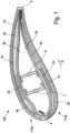
- FIG 4 shows an example of a swept rotor blade shell 110a in a top view, the rotor blade shell 110a extending from a shell root 400 to a shell tip 401 in a longitudinal direction L and from a shell trailing edge 8 to a shell leading edge 9 in a transverse direction Q.
- the front edge 9 of the shell and the rear edge 8 of the shell are curved along the longitudinal direction L, so that there is a curve in the direction of the rear edge curved profile of a rotor blade crest 403, which defines the maximum overall height of the cross section of the rotor blade shell 110a along the longitudinal direction L.
- a pitch axis 404 is also shown, about which the rotor blade shell 110a or the corresponding rotor blade can be rotated during operation to set an angle of attack. Due to the curvature of the rear and front edges 8, 9 of the shell, the course of the rotor blade crest 403 deviates from the course of the pitch axis 404. In particular, the rotor blade crest 400 curves away from the pitch axis 404 in the direction of the trailing edge 8 in the region of the shell tip 401 .
- FIG 5 shows an example of a swept rotor blade shell 110a with a rotor blade belt 12, which extends in a first section A from a shell root 400 over only part of the total length of the rotor blade shell 110a along a longitudinal direction L of the rotor blade shell 110a.
- the rotor blade belt 12 ends at an end a of the first section A which faces a shell tip 401 and which is followed by a second section B.
- the end a of the first section A facing the shell tip 401 is located where a distance between a shell front edge 9 and the rotor blade belt 12 assumes a predetermined value.
- the rotor blade shell 11a has at least one fiber layer 50 in the second region B, which extends in a transverse direction Q from a shell rear edge 8 to the shell front edge 9 and contains fibers, of which a predominant part, preferably more than 60%, in particular more than 80%, extends in the longitudinal direction L.
- This fiber layer 50 can in particular be designed as a so-called full-chord UD layer, in which all fibers extend unidirectionally in the longitudinal direction L.
- the fiber layer 50 is part of a layer system (not shown) which extends along the longitudinal direction from the shell root 400 to the shell tip 401, i.e. both in the first and in the second section A,B.
- the rotor blade belt 12 is arranged essentially along a pitch axis 404 about which the rotor blade shell 110a can be rotated during operation to set an angle of attack.
- a rotor blade crest also runs in the first area A 403, which defines the overall height of the rotor blade shell 110a along the longitudinal direction L, along the pitch axis 404, the rotor blade crest 403 being curved toward the trailing edge 8 in the second region B due to the sweep of the rotor blade shell 110a.
- the rotor blade belt 12 thus ends at the end a of the first section A facing the shell tip 401, where the rotor blade crest 403 begins to deviate significantly from the rectilinear course of the pitch axis 404 and the rotor blade belt 12 comes so close to the shell front edge 9 that it can no longer go any further can be continued in the longitudinal direction L.
Landscapes
- Engineering & Computer Science (AREA)
- Mechanical Engineering (AREA)
- Architecture (AREA)
- Civil Engineering (AREA)
- Structural Engineering (AREA)
- Life Sciences & Earth Sciences (AREA)
- Sustainable Development (AREA)
- Sustainable Energy (AREA)
- Chemical & Material Sciences (AREA)
- Combustion & Propulsion (AREA)
- General Engineering & Computer Science (AREA)
- Wind Motors (AREA)
Claims (9)
- Coque de pale de rotor (110a, 110b) pour une pale de rotor (100) d'une éolienne, dans laquelle la coque de pale de rotor (110a, 110b) s'étend à partir d'un pied de coque (400) dans une direction longitudinale (L) vers un bout de coque (401) et à partir d'un bord arrière de coque (8) dans une direction transversale (Q) vers un bord avant de coque (9) et présente un système de couches s'étendant dans la direction longitudinale (L), lequel contient au moins une couche centrale et deux stratifiés (1a, 2b, 5a, 5b, 21, 51), lesquels sont disposés sur les faces opposées l'une à l'autre de la couche centrale, dans laquelle- une partie de la couche centrale est formée dans une première section (A) de la coque de pale de rotor (110a, 110b) par une courroie de pale de rotor (2a, 2b, 12) s'étendant dans la direction longitudinale (L), qui termine sur une extrémité (a) de la première section (A) tournée vers le bout de coque, et- au moins un des deux stratifiés (1a, 2b, 5a, 5b, 21, 51) présente dans une seconde section (B) de la coque de pale de rotor (110a, 110b), qui se raccorde sur l'extrémité (a) de la première section (A) tournée vers le bout de coque à la première section (A) et s'étend sensiblement jusqu'au bout de coque, au moins une strate de fibres (11a, 11b, 15a, 15b, 20, 50), qui s'étend dans la direction transversale (Q) à partir du bord arrière de coque (8) vers le bord avant de coque (9),caractérisée en ce que
la au moins une strate de fibres (11a, 11b, 15a, 15b, 20, 50) contient des fibres, dont une majeure partie, de préférence plus de 60 %, en particulier plus de 80 %, s'étend dans la direction longitudinale (L), la première section (A) présente sur l'extrémité (a) tournée vers le bout de coque une zone de transition (U), dans laquelle la courroie de pale de rotor (2a, 2b, 12) s'amincit, et les strates de fibres (11a, 11b, 15a, 15b, 20, 50) s'étendent à partir de la seconde section (B) au moins en partie jusque dans la zone de transition (U), dans laquelle le nombre de strates de fibres (11a, 11b, 15a, 15b, 20, 50) avec des fibres, dont une majeure partie s'étend dans la direction longitudinale (L), augmente à partir de la zone de transition (U) jusqu'à la seconde section (B). - Coque de pale de rotor (110a, 110b) selon la revendication 1, dans laquelle sensiblement toutes les fibres de la au moins une strate de fibres (11a, 11b, 15a, 15b, 20, 50) sont orientées dans la direction longitudinale (L) et/ou la au moins une strate de fibres (11a, 11b, 15a, 15b, 20, 50) est réalisée en tant que couche unidirectionnelle.
- Coque de pale de rotor (110a, 110b) selon l'une quelconque des revendications 1 ou 2, dans laquelle le nombre des strates de fibres (20, 50) dans la zone de transition (U) augmente à mesure que l'épaisseur de la courroie de pale de rotor (12) diminue.
- Coque de pale de rotor (110a, 110b) selon l'une quelconque des revendications précédentes, dans laquelle la couche centrale présente un matériau central (4a, 4b, 3a, 3b, 14a, 14b, 30), lequel entoure la courroie de pale de rotor (2a, 2b, 12) dans la première section (A).
- Coque de pale de rotor (110a, 110b) selon l'une quelconque des revendications précédentes, dans laquelle le système de couches présente au moins une couche de recouvrement (10), qui est disposée sur une face d'au moins un des stratifiés (1a, 2b, 5a, 5b, 21, 51) opposée à la couche centrale et forme une face extérieure ou une face intérieure de la coque de pale de rotor (110a, 110b).
- Coque de pale de rotor (110a, 110b) selon l'une quelconque des revendications précédentes, dans laquelle le bord avant de coque (9) et le bord arrière de coque (8) présentent le long de la direction longitudinale (L) une courbure, de sorte qu'un peigne de pale de rotor (400) courbé en direction du bord arrière (9), lequel est défini par le tracé de la hauteur de construction maximale de la section transversale de la coque de pale de rotor (110a, 110b) le long de la direction longitudinale (L), est produit.
- Coque de pale de rotor (110a, 110b) selon la revendication 6, dans laquelle la position de l'extrémité (a) de la première section (A) tournée vers le bout de coque est fixée par une distance prédéfinie entre la courroie de pale de rotor (2a, 2b, 12) et le bord avant (9) courbé.
- Pale de rotor (100) pour une éolienne, dans laquelle la pale de rotor (100) présente au moins une coque de pale de rotor (110a, 110b) selon l'une quelconque des revendications précédentes.
- Eolienne avec au moins une pale de rotor (100) selon la revendication 8.
Applications Claiming Priority (2)
| Application Number | Priority Date | Filing Date | Title |
|---|---|---|---|
| DE102019000054.4A DE102019000054A1 (de) | 2019-01-08 | 2019-01-08 | Rotorblattschale Rotorblatt und Windenergieanlage |
| PCT/EP2019/085907 WO2020144020A1 (fr) | 2019-01-08 | 2019-12-18 | Coque de pale de rotor, pale de rotor et éolienne |
Publications (2)
| Publication Number | Publication Date |
|---|---|
| EP3908744A1 EP3908744A1 (fr) | 2021-11-17 |
| EP3908744B1 true EP3908744B1 (fr) | 2023-03-22 |
Family
ID=69104397
Family Applications (1)
| Application Number | Title | Priority Date | Filing Date |
|---|---|---|---|
| EP19831674.7A Active EP3908744B1 (fr) | 2019-01-08 | 2019-12-18 | Coque de pale de rotor, pale de rotor et éolienne |
Country Status (5)
| Country | Link |
|---|---|
| EP (1) | EP3908744B1 (fr) |
| DE (1) | DE102019000054A1 (fr) |
| DK (1) | DK3908744T3 (fr) |
| ES (1) | ES2943514T3 (fr) |
| WO (1) | WO2020144020A1 (fr) |
Family Cites Families (8)
| Publication number | Priority date | Publication date | Assignee | Title |
|---|---|---|---|---|
| US8079819B2 (en) * | 2009-05-21 | 2011-12-20 | Zuteck Michael D | Optimization of premium fiber material usage in wind turbine spars |
| US20110052407A1 (en) * | 2009-08-25 | 2011-03-03 | Zuteck Michael D | Swept blades utilizing asymmetric double biased fabrics |
| US10137542B2 (en) * | 2010-01-14 | 2018-11-27 | Senvion Gmbh | Wind turbine rotor blade components and machine for making same |
| DE102011003602B4 (de) * | 2011-02-03 | 2014-05-15 | Senvion Se | Sicherungssystem für ein Rotorblatt einer Windenergieanlage, Rotorblatt und Windenergieanlage |
| DE202013007886U1 (de) * | 2013-09-06 | 2014-12-08 | Nordex Energy Gmbh | Windenergieanlagenrotorblatt mit passiver Lastreduzierung |
| DE102016000292A1 (de) * | 2016-01-15 | 2017-07-20 | Senvion Gmbh | Rotorblatt einer Windenergieanlage und Verfahren zum Herstellen eines Rotorblatts |
| DE102016006632A1 (de) * | 2016-06-03 | 2017-12-07 | Senvion Gmbh | Verfahren zur Bestimmung einer Positionierung eines Rotorblattgurtes, Rotorblatt und Windenergieanlage |
| DE102017112721A1 (de) * | 2017-06-09 | 2018-12-13 | Wobben Properties Gmbh | Verfahren zum Herstellen eines Windenergieanlagen-Rotorblattes |
-
2019
- 2019-01-08 DE DE102019000054.4A patent/DE102019000054A1/de not_active Withdrawn
- 2019-12-18 EP EP19831674.7A patent/EP3908744B1/fr active Active
- 2019-12-18 DK DK19831674.7T patent/DK3908744T3/da active
- 2019-12-18 ES ES19831674T patent/ES2943514T3/es active Active
- 2019-12-18 WO PCT/EP2019/085907 patent/WO2020144020A1/fr not_active Ceased
Also Published As
| Publication number | Publication date |
|---|---|
| WO2020144020A1 (fr) | 2020-07-16 |
| ES2943514T3 (es) | 2023-06-13 |
| DE102019000054A1 (de) | 2020-07-09 |
| DK3908744T3 (da) | 2023-05-01 |
| EP3908744A1 (fr) | 2021-11-17 |
Similar Documents
| Publication | Publication Date | Title |
|---|---|---|
| EP2904262B1 (fr) | Composant composite pour la pale de rotor d'une éolienne | |
| EP2363599B2 (fr) | Pale de rotor pour une éolienne, éolienne et procédé de fabrication d'une pale de rotor | |
| DE102007020339B4 (de) | Rotorblatt für eine Windturbine | |
| DE2451860A1 (de) | Rotorblatt aus kunststoffmaterial | |
| DE2826656C3 (de) | Anschlußelement für einen Flügel aus faserverstärktem Kunststoff | |
| DE102006022279A1 (de) | Rotorblatt für eine Windenergieanlage | |
| EP3396155B1 (fr) | Pale de rotor d'une éolienne, procédé de fabrication d'une telle pale, et utilisation d'un élément de liaison | |
| WO2009095175A2 (fr) | Pale de rotor pour éoliennes | |
| WO2006039953A1 (fr) | Pale de rotor d'une centrale eolienne | |
| DE2856400C2 (de) | Tragflügel, insbesondere für Drehflügelflugzeuge | |
| DE202013007886U1 (de) | Windenergieanlagenrotorblatt mit passiver Lastreduzierung | |
| EP2568166B1 (fr) | Pale de rotor d'éolienne dotée d'un rebord arrière à profil épais | |
| EP3551438B1 (fr) | Membrure de bord de fuite d'une pale de rotor d'une installation éolienne, pale de rotor et procédé de fabrication d'une membrure de bord de fuite | |
| DE102011084433A1 (de) | Komponente, Verstärkungsbauteil, Strukturanordnung, Luft- oder Raumfahrzeug sowie Verfahren | |
| EP3908744B1 (fr) | Coque de pale de rotor, pale de rotor et éolienne | |
| EP3994351B1 (fr) | Pale de rotor pour une éolienne, segment de pale de rotor, éolienne et procédé pour la fabrication d'une pale de rotor | |
| EP3356669B1 (fr) | Pale de rotor d'éolienne et éolienne | |
| WO2000003769A1 (fr) | Crosse de hockey | |
| DE202011051341U1 (de) | Stegformation im Rotorblatttip | |
| WO2017148669A1 (fr) | Dentelures à rainures de décharge | |
| EP3469211B1 (fr) | Pale de rotor, éolienne et procédé de montage et de fabrication d'une pale de rotor | |
| EP3015702A1 (fr) | Pale de rotor pour une eolienne et procede de fabrication d'une pale de rotor | |
| DE102016000294A1 (de) | Rotorblatt mit Verstärkungs-Fasergelege und Verfahren zum Herstellen eines solchen Rotorblatts | |
| DE102018009336A1 (de) | Rotorblattform und Verfahren zur Herstellung eines Rotorblattes für eine Windenergieanlage sowie Windenergieanlage | |
| DE29806408U1 (de) | Deckhaut-Steg-Struktur |
Legal Events
| Date | Code | Title | Description |
|---|---|---|---|
| STAA | Information on the status of an ep patent application or granted ep patent |
Free format text: STATUS: UNKNOWN |
|
| STAA | Information on the status of an ep patent application or granted ep patent |
Free format text: STATUS: THE INTERNATIONAL PUBLICATION HAS BEEN MADE |
|
| PUAI | Public reference made under article 153(3) epc to a published international application that has entered the european phase |
Free format text: ORIGINAL CODE: 0009012 |
|
| STAA | Information on the status of an ep patent application or granted ep patent |
Free format text: STATUS: REQUEST FOR EXAMINATION WAS MADE |
|
| 17P | Request for examination filed |
Effective date: 20210628 |
|
| AK | Designated contracting states |
Kind code of ref document: A1 Designated state(s): AL AT BE BG CH CY CZ DE DK EE ES FI FR GB GR HR HU IE IS IT LI LT LU LV MC MK MT NL NO PL PT RO RS SE SI SK SM TR |
|
| RAP3 | Party data changed (applicant data changed or rights of an application transferred) |
Owner name: SIEMENS GAMESA RENEWABLE ENERGY SERVICE GMBH |
|
| DAV | Request for validation of the european patent (deleted) | ||
| DAX | Request for extension of the european patent (deleted) | ||
| GRAP | Despatch of communication of intention to grant a patent |
Free format text: ORIGINAL CODE: EPIDOSNIGR1 |
|
| STAA | Information on the status of an ep patent application or granted ep patent |
Free format text: STATUS: GRANT OF PATENT IS INTENDED |
|
| INTG | Intention to grant announced |
Effective date: 20221024 |
|
| GRAS | Grant fee paid |
Free format text: ORIGINAL CODE: EPIDOSNIGR3 |
|
| GRAA | (expected) grant |
Free format text: ORIGINAL CODE: 0009210 |
|
| STAA | Information on the status of an ep patent application or granted ep patent |
Free format text: STATUS: THE PATENT HAS BEEN GRANTED |
|
| AK | Designated contracting states |
Kind code of ref document: B1 Designated state(s): AL AT BE BG CH CY CZ DE DK EE ES FI FR GB GR HR HU IE IS IT LI LT LU LV MC MK MT NL NO PL PT RO RS SE SI SK SM TR |
|
| REG | Reference to a national code |
Ref country code: GB Ref legal event code: FG4D Free format text: NOT ENGLISH |
|
| REG | Reference to a national code |
Ref country code: CH Ref legal event code: EP |
|
| REG | Reference to a national code |
Ref country code: DE Ref legal event code: R096 Ref document number: 502019007301 Country of ref document: DE |
|
| REG | Reference to a national code |
Ref country code: IE Ref legal event code: FG4D Free format text: LANGUAGE OF EP DOCUMENT: GERMAN |
|
| REG | Reference to a national code |
Ref country code: AT Ref legal event code: REF Ref document number: 1555431 Country of ref document: AT Kind code of ref document: T Effective date: 20230415 |
|
| REG | Reference to a national code |
Ref country code: DK Ref legal event code: T3 Effective date: 20230426 |
|
| REG | Reference to a national code |
Ref country code: ES Ref legal event code: FG2A Ref document number: 2943514 Country of ref document: ES Kind code of ref document: T3 Effective date: 20230613 |
|
| REG | Reference to a national code |
Ref country code: LT Ref legal event code: MG9D |
|
| REG | Reference to a national code |
Ref country code: NL Ref legal event code: MP Effective date: 20230322 |
|
| PG25 | Lapsed in a contracting state [announced via postgrant information from national office to epo] |
Ref country code: RS Free format text: LAPSE BECAUSE OF FAILURE TO SUBMIT A TRANSLATION OF THE DESCRIPTION OR TO PAY THE FEE WITHIN THE PRESCRIBED TIME-LIMIT Effective date: 20230322 Ref country code: NO Free format text: LAPSE BECAUSE OF FAILURE TO SUBMIT A TRANSLATION OF THE DESCRIPTION OR TO PAY THE FEE WITHIN THE PRESCRIBED TIME-LIMIT Effective date: 20230622 Ref country code: LV Free format text: LAPSE BECAUSE OF FAILURE TO SUBMIT A TRANSLATION OF THE DESCRIPTION OR TO PAY THE FEE WITHIN THE PRESCRIBED TIME-LIMIT Effective date: 20230322 Ref country code: LT Free format text: LAPSE BECAUSE OF FAILURE TO SUBMIT A TRANSLATION OF THE DESCRIPTION OR TO PAY THE FEE WITHIN THE PRESCRIBED TIME-LIMIT Effective date: 20230322 Ref country code: HR Free format text: LAPSE BECAUSE OF FAILURE TO SUBMIT A TRANSLATION OF THE DESCRIPTION OR TO PAY THE FEE WITHIN THE PRESCRIBED TIME-LIMIT Effective date: 20230322 |
|
| PG25 | Lapsed in a contracting state [announced via postgrant information from national office to epo] |
Ref country code: SE Free format text: LAPSE BECAUSE OF FAILURE TO SUBMIT A TRANSLATION OF THE DESCRIPTION OR TO PAY THE FEE WITHIN THE PRESCRIBED TIME-LIMIT Effective date: 20230322 Ref country code: NL Free format text: LAPSE BECAUSE OF FAILURE TO SUBMIT A TRANSLATION OF THE DESCRIPTION OR TO PAY THE FEE WITHIN THE PRESCRIBED TIME-LIMIT Effective date: 20230322 Ref country code: GR Free format text: LAPSE BECAUSE OF FAILURE TO SUBMIT A TRANSLATION OF THE DESCRIPTION OR TO PAY THE FEE WITHIN THE PRESCRIBED TIME-LIMIT Effective date: 20230623 Ref country code: FI Free format text: LAPSE BECAUSE OF FAILURE TO SUBMIT A TRANSLATION OF THE DESCRIPTION OR TO PAY THE FEE WITHIN THE PRESCRIBED TIME-LIMIT Effective date: 20230322 |
|
| PG25 | Lapsed in a contracting state [announced via postgrant information from national office to epo] |
Ref country code: SM Free format text: LAPSE BECAUSE OF FAILURE TO SUBMIT A TRANSLATION OF THE DESCRIPTION OR TO PAY THE FEE WITHIN THE PRESCRIBED TIME-LIMIT Effective date: 20230322 Ref country code: RO Free format text: LAPSE BECAUSE OF FAILURE TO SUBMIT A TRANSLATION OF THE DESCRIPTION OR TO PAY THE FEE WITHIN THE PRESCRIBED TIME-LIMIT Effective date: 20230322 Ref country code: PT Free format text: LAPSE BECAUSE OF FAILURE TO SUBMIT A TRANSLATION OF THE DESCRIPTION OR TO PAY THE FEE WITHIN THE PRESCRIBED TIME-LIMIT Effective date: 20230724 Ref country code: EE Free format text: LAPSE BECAUSE OF FAILURE TO SUBMIT A TRANSLATION OF THE DESCRIPTION OR TO PAY THE FEE WITHIN THE PRESCRIBED TIME-LIMIT Effective date: 20230322 |
|
| PG25 | Lapsed in a contracting state [announced via postgrant information from national office to epo] |
Ref country code: SK Free format text: LAPSE BECAUSE OF FAILURE TO SUBMIT A TRANSLATION OF THE DESCRIPTION OR TO PAY THE FEE WITHIN THE PRESCRIBED TIME-LIMIT Effective date: 20230322 Ref country code: PL Free format text: LAPSE BECAUSE OF FAILURE TO SUBMIT A TRANSLATION OF THE DESCRIPTION OR TO PAY THE FEE WITHIN THE PRESCRIBED TIME-LIMIT Effective date: 20230322 Ref country code: IS Free format text: LAPSE BECAUSE OF FAILURE TO SUBMIT A TRANSLATION OF THE DESCRIPTION OR TO PAY THE FEE WITHIN THE PRESCRIBED TIME-LIMIT Effective date: 20230722 |
|
| REG | Reference to a national code |
Ref country code: DE Ref legal event code: R097 Ref document number: 502019007301 Country of ref document: DE |
|
| PLBE | No opposition filed within time limit |
Free format text: ORIGINAL CODE: 0009261 |
|
| STAA | Information on the status of an ep patent application or granted ep patent |
Free format text: STATUS: NO OPPOSITION FILED WITHIN TIME LIMIT |
|
| PG25 | Lapsed in a contracting state [announced via postgrant information from national office to epo] |
Ref country code: SI Free format text: LAPSE BECAUSE OF FAILURE TO SUBMIT A TRANSLATION OF THE DESCRIPTION OR TO PAY THE FEE WITHIN THE PRESCRIBED TIME-LIMIT Effective date: 20230322 Ref country code: CZ Free format text: LAPSE BECAUSE OF FAILURE TO SUBMIT A TRANSLATION OF THE DESCRIPTION OR TO PAY THE FEE WITHIN THE PRESCRIBED TIME-LIMIT Effective date: 20230322 |
|
| 26N | No opposition filed |
Effective date: 20240102 |
|
| PG25 | Lapsed in a contracting state [announced via postgrant information from national office to epo] |
Ref country code: IT Free format text: LAPSE BECAUSE OF FAILURE TO SUBMIT A TRANSLATION OF THE DESCRIPTION OR TO PAY THE FEE WITHIN THE PRESCRIBED TIME-LIMIT Effective date: 20230322 |
|
| REG | Reference to a national code |
Ref country code: DE Ref legal event code: R119 Ref document number: 502019007301 Country of ref document: DE |
|
| REG | Reference to a national code |
Ref country code: DK Ref legal event code: EBP Effective date: 20231231 |
|
| REG | Reference to a national code |
Ref country code: CH Ref legal event code: PL |
|
| PG25 | Lapsed in a contracting state [announced via postgrant information from national office to epo] |
Ref country code: LU Free format text: LAPSE BECAUSE OF NON-PAYMENT OF DUE FEES Effective date: 20231218 |
|
| PG25 | Lapsed in a contracting state [announced via postgrant information from national office to epo] |
Ref country code: MC Free format text: LAPSE BECAUSE OF FAILURE TO SUBMIT A TRANSLATION OF THE DESCRIPTION OR TO PAY THE FEE WITHIN THE PRESCRIBED TIME-LIMIT Effective date: 20230322 |
|
| GBPC | Gb: european patent ceased through non-payment of renewal fee |
Effective date: 20231218 |
|
| REG | Reference to a national code |
Ref country code: BE Ref legal event code: MM Effective date: 20231231 |
|
| PG25 | Lapsed in a contracting state [announced via postgrant information from national office to epo] |
Ref country code: MC Free format text: LAPSE BECAUSE OF FAILURE TO SUBMIT A TRANSLATION OF THE DESCRIPTION OR TO PAY THE FEE WITHIN THE PRESCRIBED TIME-LIMIT Effective date: 20230322 Ref country code: LU Free format text: LAPSE BECAUSE OF NON-PAYMENT OF DUE FEES Effective date: 20231218 |
|
| REG | Reference to a national code |
Ref country code: IE Ref legal event code: MM4A |
|
| PG25 | Lapsed in a contracting state [announced via postgrant information from national office to epo] |
Ref country code: DE Free format text: LAPSE BECAUSE OF NON-PAYMENT OF DUE FEES Effective date: 20240702 Ref country code: IE Free format text: LAPSE BECAUSE OF NON-PAYMENT OF DUE FEES Effective date: 20231218 |
|
| PG25 | Lapsed in a contracting state [announced via postgrant information from national office to epo] |
Ref country code: GB Free format text: LAPSE BECAUSE OF NON-PAYMENT OF DUE FEES Effective date: 20231218 |
|
| PG25 | Lapsed in a contracting state [announced via postgrant information from national office to epo] |
Ref country code: BE Free format text: LAPSE BECAUSE OF NON-PAYMENT OF DUE FEES Effective date: 20231231 |
|
| PG25 | Lapsed in a contracting state [announced via postgrant information from national office to epo] |
Ref country code: FR Free format text: LAPSE BECAUSE OF NON-PAYMENT OF DUE FEES Effective date: 20231231 |
|
| PG25 | Lapsed in a contracting state [announced via postgrant information from national office to epo] |
Ref country code: CH Free format text: LAPSE BECAUSE OF NON-PAYMENT OF DUE FEES Effective date: 20231231 |
|
| PG25 | Lapsed in a contracting state [announced via postgrant information from national office to epo] |
Ref country code: IE Free format text: LAPSE BECAUSE OF NON-PAYMENT OF DUE FEES Effective date: 20231218 Ref country code: GB Free format text: LAPSE BECAUSE OF NON-PAYMENT OF DUE FEES Effective date: 20231218 Ref country code: FR Free format text: LAPSE BECAUSE OF NON-PAYMENT OF DUE FEES Effective date: 20231231 Ref country code: DE Free format text: LAPSE BECAUSE OF NON-PAYMENT OF DUE FEES Effective date: 20240702 Ref country code: CH Free format text: LAPSE BECAUSE OF NON-PAYMENT OF DUE FEES Effective date: 20231231 Ref country code: BE Free format text: LAPSE BECAUSE OF NON-PAYMENT OF DUE FEES Effective date: 20231231 |
|
| PG25 | Lapsed in a contracting state [announced via postgrant information from national office to epo] |
Ref country code: BG Free format text: LAPSE BECAUSE OF FAILURE TO SUBMIT A TRANSLATION OF THE DESCRIPTION OR TO PAY THE FEE WITHIN THE PRESCRIBED TIME-LIMIT Effective date: 20230322 |
|
| PG25 | Lapsed in a contracting state [announced via postgrant information from national office to epo] |
Ref country code: BG Free format text: LAPSE BECAUSE OF FAILURE TO SUBMIT A TRANSLATION OF THE DESCRIPTION OR TO PAY THE FEE WITHIN THE PRESCRIBED TIME-LIMIT Effective date: 20230322 |
|
| PG25 | Lapsed in a contracting state [announced via postgrant information from national office to epo] |
Ref country code: DK Free format text: LAPSE BECAUSE OF NON-PAYMENT OF DUE FEES Effective date: 20231231 |
|
| REG | Reference to a national code |
Ref country code: ES Ref legal event code: FD2A Effective date: 20250127 |
|
| PG25 | Lapsed in a contracting state [announced via postgrant information from national office to epo] |
Ref country code: DK Free format text: LAPSE BECAUSE OF NON-PAYMENT OF DUE FEES Effective date: 20231231 |
|
| PG25 | Lapsed in a contracting state [announced via postgrant information from national office to epo] |
Ref country code: ES Free format text: LAPSE BECAUSE OF NON-PAYMENT OF DUE FEES Effective date: 20231219 |
|
| PG25 | Lapsed in a contracting state [announced via postgrant information from national office to epo] |
Ref country code: CY Free format text: LAPSE BECAUSE OF FAILURE TO SUBMIT A TRANSLATION OF THE DESCRIPTION OR TO PAY THE FEE WITHIN THE PRESCRIBED TIME-LIMIT; INVALID AB INITIO Effective date: 20191218 |
|
| PG25 | Lapsed in a contracting state [announced via postgrant information from national office to epo] |
Ref country code: HU Free format text: LAPSE BECAUSE OF FAILURE TO SUBMIT A TRANSLATION OF THE DESCRIPTION OR TO PAY THE FEE WITHIN THE PRESCRIBED TIME-LIMIT; INVALID AB INITIO Effective date: 20191218 |
|
| PG25 | Lapsed in a contracting state [announced via postgrant information from national office to epo] |
Ref country code: TR Free format text: LAPSE BECAUSE OF FAILURE TO SUBMIT A TRANSLATION OF THE DESCRIPTION OR TO PAY THE FEE WITHIN THE PRESCRIBED TIME-LIMIT Effective date: 20230322 |
|
| REG | Reference to a national code |
Ref country code: AT Ref legal event code: MM01 Ref document number: 1555431 Country of ref document: AT Kind code of ref document: T Effective date: 20241218 |
|
| PG25 | Lapsed in a contracting state [announced via postgrant information from national office to epo] |
Ref country code: AT Free format text: LAPSE BECAUSE OF NON-PAYMENT OF DUE FEES Effective date: 20241218 |
|
| PGFP | Annual fee paid to national office [announced via postgrant information from national office to epo] |
Ref country code: AT Payment date: 20260410 Year of fee payment: 5 |