EP3909703A1 - Verfahren zum stranggiessen von brammen - Google Patents
Verfahren zum stranggiessen von brammen Download PDFInfo
- Publication number
- EP3909703A1 EP3909703A1 EP20765989.7A EP20765989A EP3909703A1 EP 3909703 A1 EP3909703 A1 EP 3909703A1 EP 20765989 A EP20765989 A EP 20765989A EP 3909703 A1 EP3909703 A1 EP 3909703A1
- Authority
- EP
- European Patent Office
- Prior art keywords
- mold
- slab
- copper plates
- molten steel
- continuous casting
- Prior art date
- Legal status (The legal status is an assumption and is not a legal conclusion. Google has not performed a legal analysis and makes no representation as to the accuracy of the status listed.)
- Granted
Links
Images



Classifications
-
- B—PERFORMING OPERATIONS; TRANSPORTING
- B22—CASTING; POWDER METALLURGY
- B22D—CASTING OF METALS; CASTING OF OTHER SUBSTANCES BY THE SAME PROCESSES OR DEVICES
- B22D46/00—Controlling, supervising, not restricted to casting covered by a single main group, e.g. for safety reasons
-
- B—PERFORMING OPERATIONS; TRANSPORTING
- B22—CASTING; POWDER METALLURGY
- B22D—CASTING OF METALS; CASTING OF OTHER SUBSTANCES BY THE SAME PROCESSES OR DEVICES
- B22D11/00—Continuous casting of metals, i.e. casting in indefinite lengths
- B22D11/16—Controlling or regulating processes or operations
- B22D11/20—Controlling or regulating processes or operations for removing cast stock
- B22D11/201—Controlling or regulating processes or operations for removing cast stock responsive to molten metal level or slag level
- B22D11/202—Controlling or regulating processes or operations for removing cast stock responsive to molten metal level or slag level by measuring temperature
-
- B—PERFORMING OPERATIONS; TRANSPORTING
- B22—CASTING; POWDER METALLURGY
- B22D—CASTING OF METALS; CASTING OF OTHER SUBSTANCES BY THE SAME PROCESSES OR DEVICES
- B22D11/00—Continuous casting of metals, i.e. casting in indefinite lengths
- B22D11/16—Controlling or regulating processes or operations
- B22D11/20—Controlling or regulating processes or operations for removing cast stock
-
- B—PERFORMING OPERATIONS; TRANSPORTING
- B22—CASTING; POWDER METALLURGY
- B22D—CASTING OF METALS; CASTING OF OTHER SUBSTANCES BY THE SAME PROCESSES OR DEVICES
- B22D11/00—Continuous casting of metals, i.e. casting in indefinite lengths
- B22D11/04—Continuous casting of metals, i.e. casting in indefinite lengths into open-ended moulds
-
- B—PERFORMING OPERATIONS; TRANSPORTING
- B22—CASTING; POWDER METALLURGY
- B22D—CASTING OF METALS; CASTING OF OTHER SUBSTANCES BY THE SAME PROCESSES OR DEVICES
- B22D11/00—Continuous casting of metals, i.e. casting in indefinite lengths
- B22D11/04—Continuous casting of metals, i.e. casting in indefinite lengths into open-ended moulds
- B22D11/041—Continuous casting of metals, i.e. casting in indefinite lengths into open-ended moulds for vertical casting
-
- B—PERFORMING OPERATIONS; TRANSPORTING
- B22—CASTING; POWDER METALLURGY
- B22D—CASTING OF METALS; CASTING OF OTHER SUBSTANCES BY THE SAME PROCESSES OR DEVICES
- B22D11/00—Continuous casting of metals, i.e. casting in indefinite lengths
- B22D11/04—Continuous casting of metals, i.e. casting in indefinite lengths into open-ended moulds
- B22D11/055—Cooling the moulds
-
- B—PERFORMING OPERATIONS; TRANSPORTING
- B22—CASTING; POWDER METALLURGY
- B22D—CASTING OF METALS; CASTING OF OTHER SUBSTANCES BY THE SAME PROCESSES OR DEVICES
- B22D11/00—Continuous casting of metals, i.e. casting in indefinite lengths
- B22D11/10—Supplying or treating molten metal
- B22D11/11—Treating the molten metal
- B22D11/114—Treating the molten metal by using agitating or vibrating means
- B22D11/115—Treating the molten metal by using agitating or vibrating means by using magnetic fields
-
- B—PERFORMING OPERATIONS; TRANSPORTING
- B22—CASTING; POWDER METALLURGY
- B22D—CASTING OF METALS; CASTING OF OTHER SUBSTANCES BY THE SAME PROCESSES OR DEVICES
- B22D11/00—Continuous casting of metals, i.e. casting in indefinite lengths
- B22D11/16—Controlling or regulating processes or operations
- B22D11/18—Controlling or regulating processes or operations for pouring
- B22D11/181—Controlling or regulating processes or operations for pouring responsive to molten metal level or slag level
- B22D11/182—Controlling or regulating processes or operations for pouring responsive to molten metal level or slag level by measuring temperature
-
- B—PERFORMING OPERATIONS; TRANSPORTING
- B22—CASTING; POWDER METALLURGY
- B22D—CASTING OF METALS; CASTING OF OTHER SUBSTANCES BY THE SAME PROCESSES OR DEVICES
- B22D11/00—Continuous casting of metals, i.e. casting in indefinite lengths
- B22D11/16—Controlling or regulating processes or operations
- B22D11/22—Controlling or regulating processes or operations for cooling cast stock or mould
-
- B—PERFORMING OPERATIONS; TRANSPORTING
- B22—CASTING; POWDER METALLURGY
- B22D—CASTING OF METALS; CASTING OF OTHER SUBSTANCES BY THE SAME PROCESSES OR DEVICES
- B22D2/00—Arrangement of indicating or measuring devices, e.g. for temperature or viscosity of the fused mass
- B22D2/006—Arrangement of indicating or measuring devices, e.g. for temperature or viscosity of the fused mass for the temperature of the molten metal
Definitions
- the present invention relates to a continuous casting method of a cast slab. More specifically, the present invention relates to a continuous casting method of a cast slab in which the temperatures of copper plates on wide face of mold are measured during continuous casting to control a variation of the measured temperatures of the copper plates on wide face of mold to be within a predetermined range over the mold width direction.
- Patent Literature 1 proposes a method for applying a magnetic field to molten steel in a mold.
- Patent Literature 2 proposes a method in which a plurality of temperature measuring elements are arranged in the width direction of the rear surfaces of mold copper plates so as to measure the temperature distribution in the mold copper plates in the width direction of a mold by using the temperature measuring elements and in which a surface defect in a slab is determined on the basis of the temperature distribution in the width direction of the mold.
- Patent Literature 3 proposes a method in which the temperatures of copper plates on wide face of mold are measured by using temperature measuring elements, which are embedded in the rear surfaces of the copper plates on wide face of mold, while applying a travelling magnetic field that causes molten steel in a mold to swirl in the horizontal direction and in which a surface defect in a slab is determined on the basis of the measured temperatures of the mold copper plates. More specifically, in this method, measurement results obtained by temperature measuring elements that are symmetrically positioned using the axis of a mold space as the symmetry axis are compared, and when the ratio of one of the measured temperatures that is lower than the other to the other measured temperature, which is higher, is smaller than 0.85, it is determined that a defect has occurred in the surface of the slab.
- Patent Literature 2 and Patent Literature 3 a defect on the surface of a slab is determined by capturing changes in the temperatures of the mold copper plates with changes in the flow of the molten steel in the mold, and it is recommended to measure the temperatures of the mold copper plates in a region within 135 mm from the meniscus of the molten steel in the mold in a slab withdrawal direction.
- non-uniform inflow of mold powder and formation of a gap (called "air gap”) between a mold and a solidified shell are known. That is to say, as a result of non-uniform inflow of mold powder, solidified shell is stuck to the mold in a portion in which the inflow amount of the mold powder is small, and this results in breakout.
- an air gap the amount of heat removed from the molten steel to the mold is locally reduced, and a portion having a small thickness is formed in the solidified shell.
- this portion of the solidified shell is not capable of withstanding the ferrostatic pressure inside the solidified shell, cracks are generated in the portion, and breakout occurs.
- Non-uniform inflow of the mold powder also forms such a portion of the solidified shell having a small thickness, and this causes a breakout.
- the present invention has been made in view of the above situation, and it is an object of the present invention to provide a continuous casting method of a cast slab, the method capable of measuring the temperatures of large portions of copper plates on wide face of mold during continuous casting of a cast slab and adjusting casting conditions in such a manner that variations in the measured temperatures of the copper plates on wide face of mold in the width direction of a mold are within a predetermined range so as to achieve both a high productivity of a continuous casting machine and manufacture of a high-quality slab.
- the gist of the present invention for solving the above problem is as follows.
- a continuous casting method of a cast slab in which temperature measuring elements are arranged in each of opposedly facing copper plates on wide face of mold of a mold for continuous casting and in which a steel cast slab is continuously cast while temperatures of the copper plates on wide face of mold are measured by using the temperature measuring elements.
- the temperature measuring elements are arranged such that temperature measurement points of the temperature measuring elements are positioned between a molten steel side surface of and a cooling-water slit of the copper plates on wide face of mold and such that the temperature measurement points are spaced apart from the molten steel side surface of the copper plates on wide face of mold by the same distance in a thickness direction of the copper plates.
- the temperature measurement points are arranged in a grid-like pattern in a region from a meniscus of a molten steel to a level 600 mm or more below the meniscus of a molten steel in a slab withdrawal direction at a pitch of 100 mm or smaller in the slab withdrawal direction and at a pitch of 150 mm or smaller in a width direction of the copper plates on wide face of mold.
- Values measured by the temperature measuring elements arranged closer to a center in a width direction of the cast slab than short sides of the cast slab under continuous casting at levels of 50 mm or more lower in the slab withdrawal direction than the meniscus of the molten steel in the mold are selected as evaluation targets for the temperatures of the copper plates on wide face of mold.
- a casting condition is adjusted such that a standard deviation of the values measured over the width direction of the copper plates on wide face of mold at a same level in the slab withdrawal direction is 20°C or lower.
- the casting condition is adjusted such that all the standard deviations of the values measured over the width direction of the copper plates on wide face of mold at each level in the slab withdrawal direction are 20°C or lower.
- the casting condition includes one, or two or more of three conditions that are the slab withdrawal rate, a magnetic flux density applied to the molten steel in the mold by an electromagnetic-field generating device, and a submergence depth of a submerged entry nozzle.
- the temperatures of large portions of copper plates on wide face of mold in a slab withdrawal direction and in the width direction of the copper plates on wide face of mold are measured, and casting conditions are adjusted in such a manner that variations in the temperatures measured over the width direction of the copper plates on wide face of mold at the same level in the slab withdrawal direction are small.
- an operation that achieves both a high productivity of a continuous casting machine and a high quality of a cast slab can be performed.
- Fig. 1 is a schematic sectional view of a slab continuous casting machine suitable for implementing a continuous casting method of a cast slab according to the present invention, in which a sectional front view of a continuous casting mold and a tundish is illustrated.
- a tundish 9 is disposed at a predetermined position above a continuous casting mold 6 that includes opposedly facing copper plates 7 on wide face of mold, and opposedly facing copper plates 8 on narrow face of mold which are sandwiched between the copper plates 7 on wide face of mold.
- An upper nozzle 12 is disposed in a bottom portion of the tundish 9, and a sliding nozzle 13 that includes a fixing plate 14, a sliding plate 15, and a rectifying nozzle 16 is disposed to be in contact with the lower surface of the upper nozzle 12.
- a submerged entry nozzle 17 that has a pair of outlet holes 17a is disposed to be in contact with the lower surface of the sliding nozzle 13.
- a noble gas such as argon gas, or a non-oxidizing gas, such as nitrogen gas
- a non-oxidizing gas such as nitrogen gas
- the tundish 9 has an iron shell 10 as its outer shell, and a refractory material 11 is provided on the inner side of the iron shell 10.
- Electromagnetic-field generating devices 18 are arranged on the rear surfaces of the copper plates 7 on wide face of mold in such a manner that the electromagnetic-field generating devices 18 face with each other to interpose the copper plates 7 on wide face of mold therebetween.
- Each of the electromagnetic-field generating devices 18 is connected to a power supply (not illustrated) by a wiring line and is configured such that a magnetic flux density applied by the electromagnetic-field generating device 18 and a travelling direction of a magnetic field can be controlled by the electrical power supplied from the power supply. Note that, in Fig.
- each of the electromagnetic-field generating devices 18 is not limited to having the specifications illustrated in Fig. 1 , and a device that is suitable for the characteristics of steel products to be manufactured may be suitably selected.
- Examples of such a device include a device that applies a direct-current magnetic field to molten steel so as to limit the flow of the molten steel and a device that applies an alternating-current magnetic field to molten steel so as to cause the molten steel to swirl or limit the flow of the molten steel in a given direction.
- the molten steel 1 is teemed into the tundish 9 from a ladle (not illustrated).
- the sliding plate 15 is opened, and the molten steel 1 is poured into the continuous casting mold 6 from the tundish 9.
- the molten steel 1 is flowed into the internal space of the continuous casting mold 6 through the outlet holes 17a of the submerged entry nozzle 17 while forming jet flows 5 toward the copper plates 8 on narrow face of mold.
- the molten steel 1 flowed into the internal space of the continuous casting mold 6 comes into contact with the continuous casting mold 6 and is cooled. As a result, the solidified shell 2 is formed on a surface in contact with the continuous casting mold 6.
- the outlet holes 17a are maintained submerged in the molten steel 1, and pinch rolls (not illustrated), which is disposed below the continuous casting mold 6, are driven so as to start withdrawal of a cast slab 3 that includes the solidified shell 2 as its outer shell and the unsolidified molten steel 1 therein.
- the slab withdrawal rate is increased to a predetermined slab withdrawal rate while the meniscus of the molten steel 4 in the continuous casting mold is controlled to be maintained at a substantially fixed position.
- Mold powder 19 is added to the meniscus of the molten steel 4 in the mold. The mold powder 19 melts and provides an advantageous effect of preventing oxidation of the molten steel 1 and an advantageous effect as a lubricating material by flowing into a space between the solidified shell 2 and the continuous casting mold 6.
- a method of applying magnetic fields that travel in opposite directions by using the electromagnetic-field generating devices 18, which opposedly face each other, and forming a swirling flow of the molten steel 1 in the horizontal direction on the meniscus of the molten steel 4 in the mold that is, a method of forming a flow of the molten steel that swirls in the horizontal direction along a solidified shell interface
- a method of reducing the flow velocity of the molten steel 1 in the mold by applying a direct-current static magnetic field, or the like is used depending on the purpose.
- thermocouples serving as temperature measuring elements were embedded in the opposedly facing copper plates 7 on wide face of mold in such a manner that each pair of the thermocouples face each other at approximately the same position.
- thermocouples are used as the temperature measuring elements in this case, the temperature measuring elements may be any elements as long as they can accurately measure the temperatures of the mold copper plates, and examples of such elements include optical fiber type sensors.
- the copper plates 7 on wide face of mold are each formed to have a flat surface as in a vertical-bending type slab continuous casting machine, when optical fibers are used, for example, the optical fibers may be inserted from the upper end surfaces of the copper plates 7 on wide face of mold in the slab withdrawal direction to be parallel to the surfaces of the mold long side copper plate 7 on the side on which the molten steel is present.
- the installation positions of temperature measurement points of the temperature measuring elements in the case of using thermocouples, the positions of ends of the thermocouples) in the thickness direction of the mold copper plates are set such that the distances of all the installed temperature measurement points in the thickness direction of the copper plates are the same as one another (each of the installed temperature measurement points is spaced apart from the molten steel side surface of the mold copper plate by the same distance) and such that each of the temperature measurement points is positioned between the molten steel side surface and cooling water slits (water channels through which cooling water for cooling the mold copper plates passes) of the mold long-side copper plate 7.
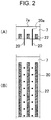
- Fig. 2 is a schematic view illustrating a specific arrangement method when thermocouples are used as temperature measuring elements.
- Fig. 2A is a cross-sectional view of a portion of one of the copper plates 7 on wide face of mold when viewed from above in the vertical direction.
- Fig. 2B is a side view of a portion of one of the copper plates 7 on wide face of mold when viewed from the side on which a water chamber (a mold-cooling-water supply/drainage device) is provided.
- a water chamber a mold-cooling-water supply/drainage device
- thermocouples 20 are arranged as temperature measuring elements, as illustrated in Fig. 2 , holes into which the thermocouples 20 are inserted are formed in portions of the rear surface of each of the copper plates 7 on wide face of mold, the portions not having cooling-water slits 22 formed therein, so as to be substantially perpendicular to the rear surface of the mold long-side copper plate 7, and the thermocouples 20 are inserted into these holes.
- the thermocouples 20 are arranged in such a manner that a temperature measurement point 20a of each of the thermocouples 20 (an end of each of the thermocouples) is positioned between a molten steel side surface 7a and the cooling-water slits 22 of the mold long-side copper plate 7.
- optical fiber sensors FBG sensors
- holes are formed between the molten steel side surfaces 7a of the copper plates 7 on wide face of mold and the cooling-water slits 22 so as to be parallel to the molten-steel-side surfaces 7a of the copper plates 7 on wide face of mold, and the optical fiber sensors are inserted into these holes.
- the temperature measurement points are located at positions similar to those in the case where thermocouples are used as the temperature measuring elements, and the positions are indicated by black dots (•) in Fig. 2 .
- the temperature measurement point of each of the temperature measuring elements be positioned between the molten steel side surface and the cooling-water slits 22 of the mold long-side copper plate 7 and be present within a distance range of 4 mm to 20 mm from the molten steel side surface 7a of the mold long-side copper plate 7.
- the distance range falls below 4 mm, cracks generated due to a heat load applied to the mold copper plates may extend to the temperature measurement points and damage the temperature measuring elements.
- the distance range exceeds 20 mm, this is not preferable because the temperature measurement responsivity deteriorates.
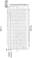
- Fig. 3 illustrates the positions at which the thermocouples are disposed in one of the copper plates 7 on wide face of mold.
- the positions at which the thermocouples are disposed are indicated by black dots (•) in Fig. 3 .
- the thermocouples were arranged to form a total of 17 rows A to Q at a pitch of 50 mm starting from positions 100 mm away from the upper end of the mold long-side copper plate 7.
- thermocouples were arranged to form a total of 27 columns 1 to 27 at a pitch of 75 mm, and the thermocouples were arranged in a grid-like pattern in the slab withdrawal direction and in the width direction of the mold long-side copper plate 7.
- thermocouples in a grid-like pattern in substantially the entire area of each of the copper plates 7 on wide face of mold, the temperature distribution in the entire copper plates 7 on wide face of mold can be measured. Note that, in Fig. 3 , although the position of the meniscus of the molten steel 4 is 80 mm away from the upper end of the mold long-side copper plate 7, the position of the meniscus of the molten steel 4 can be changed within a range of 80 ⁇ 30 mm without affecting the continuous casting operation.
- the temperature distribution in each of the copper plates on wide face of mold was measured while the cast slab 3 is continuously cast by using the above-described continuous casting mold 6.
- the obtained temperature distribution was compared with the operating state during the continuous casting.
- thermocouples that measures the temperature of one of the copper plates on wide face of mold at the portion where the air gap has been generated is likely to be lower than the temperature measured by another one of the thermocouples that is adjacent to the one thermocouple in the width direction of the mold.
- the inventors of the present invention repeatedly conducted extensive studies on an index that indicates local variations in the temperatures of the copper plates on wide face of mold.
- the studies led to the conclusion that it was most preferable to use the standard deviation of temperatures measured in the width direction of the copper plates on wide face of mold at the same position in the slab withdrawal direction.
- the inventors also found that, in this case, it was important for stable control of the continuous casting operation not to include the values measured by the thermocouples on the row higher than the level 50 mm below the meniscus of the molten steel 4 in the continuous casting mold in the evaluation because such measured values were greatly affected by fluctuations in the position of the meniscus of the molten steel.
- the values measured by the temperature measuring elements arranged at positions that are spaced downward away from the meniscus of the molten steel 4 in the continuous casting mold by 50 mm or more in the slab withdrawal direction needed to be evaluation targets.
- the values measured at positions that are closer to the center of the cast slab, which is undergoing continuous casting, than the positions of the short sides of the cast slab in the width direction of the cast slab are the evaluation targets.
- the temperatures of the copper plates on wide face of mold are low at the positions of the short sides of the cast slab, which is undergoing continuous casting, and at positions outside the positions of the short sides, and the values measured by the thermocouples included in the columns located at these positions are not the evaluation targets.
- the operation may be performed in such a manner that all the standard deviations of the temperature measurement points in the width direction of the copper plates on wide face of mold at the same position in the slab withdrawal direction are 20°C or lower.
- the casting conditions are changed even when the standard deviation does not exceed 20°C (for example, if the casting conditions are changed when the standard deviation exceeds 15°C), it will be necessary to perform excessive intervention in the operation by, for example, constantly and extremely reducing the slab withdrawal rate in order to control the standard deviation to be within a predetermined range, and there is a concern that this may actually cause deterioration of the productivity.
- the standard deviation does not exceed 20°C, it is desirable not to change the casting conditions.
- the submergence depth of the submerged entry nozzle 17 refers to the distance from the meniscus of the molten steel 4 to the upper ends of outlet holes 17a.
- an operation of changing the magnetic flux density (increasing the magnetic flux density) of each of the electromagnetic-field generating devices 18 is most preferable because it does not easily affect the productivity and the operation of the continuous casting machine.
- the length of time over which the submerged entry nozzle 17 can be used is set for each submergence depth from the standpoint of protecting a refractory material from damage. Although the submerged entry nozzle 17 is used under such limiting conditions, changing the submergence depth of the submerged entry nozzle 17 (increasing the submergence depth) is also effective.
- changes in the slab withdrawal rate decrease in the slab withdrawal rate
- the operation of the continuous casting machine is stopped, and it takes a long time to recover, and thus, it is also effective to perform control for reducing the slab withdrawal rate before such a situation occurs.
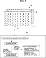
- Fig. 4 is a schematic diagram illustrating the continuous casting mold 6 in which the thermocouples 20 are embedded and an arithmetic unit 21 for performing determination and control using a standard deviation, the continuous casting mold 6 and the arithmetic unit 21 being used in the practice of the present invention.
- the thermocouples 20 are embedded in the continuous casting mold 6 at the above-mentioned appropriate positions.
- the data regarding the temperatures of the copper plates on wide face of mold measured by the thermocouples 20 is loaded by the arithmetic unit 21, and a standard deviation analysis of measured temperatures in the width direction of the copper plates on wide face of mold at the same position in the slab withdrawal direction is performed by using general-purpose statistical analysis software.
- the standard deviations in all the rows are 20°C or lower, the continuous casting operation is continued without changing the casting conditions.
- the standard deviations in all the rows be controlled to be 20°C or lower by adjusting any one of or any two or more of the magnetic flux density of each of the electromagnetic-field generating devices 18, the submergence depth of the submerged entry nozzle 17, and the slab withdrawal rate.
- the cast slab that has undergone the continuous casting is transferred to a rolling process, which is the next process.
- a cast slab with the standard deviation of 20°C or lower is transferred to the rolling process, without performing a surface inspection of the cast slab.
- a cast slab with the standard deviation exceeding 20°C is subjected to, for example, a surface inspection of the cast slab, and if there are flaws such as cracks on the surface of the cast slab, the flaws on the surface are removed by a surface grinding treatment using a scarfer, a grinder, or the like, after which the cast slab is transferred to the rolling process.
- a scarfer a grinder, or the like
- the temperatures of large portions of the copper plates 7 on wide face of mold in the slab withdrawal direction and in the width direction of the copper plates 7 on wide face of mold are measured, and the casting conditions are adjusted in such a manner that variations in the measured temperatures in the width direction of the copper plates 7 on wide face of mold at the same position in the slab withdrawal direction are small.
- the operation that achieves both a high productivity of the continuous casting machine and a high quality of the cast slab can be performed.
- the standard deviation that is to be controlled is a standard deviation of variations with respect to space in the temperature of a copper plate at a given time (measured temperatures in the width direction of the long-side copper plates at the same position in a slab withdrawal direction), and the standard deviation of variations with respect to time is not to be controlled.
- Aluminum killed molten steel was continuously cast by using a slab continuous casting machine having two strands (hereinafter referred to as "strand A” and "strand B").
- a slab continuous casting machine having two strands uses molten steel having the same composition, and thus, a comparison can be performed under substantially similar operating conditions.
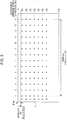
- Fig. 5 is a schematic diagram illustrating the rear surface of one of the copper plates on wide face of mold, and the positions at which the thermocouples are disposed are indicated by black dots (•) in Fig. 5 . As illustrated in Fig.
- thermocouples were arranged in a grid-like pattern such that, in the slab withdrawal direction, the thermocouples were arranged so as to form a total of 7 rows A to G at a pitch of 100 mm starting from positions 100 mm away from the upper end of each of the copper plates 7 on wide face of mold and such that, in the width direction of the mold long-side copper plate 7, the thermocouples were arranged to form a total of 14 columns 1 to 14 at a pitch of 150 mm.
- strand B was equipped with a continuous casting mold including copper plates on wide face of mold having thermocouples embedded in the rear surfaces thereof as illustrated in Fig. 6 .
- Fig. 6 is a schematic diagram illustrating the rear surface of one of the copper plates on wide face of mold, and the positions at which the thermocouples are disposed are indicated by black dots (•) in Fig. 6 . As illustrated in Fig.
- thermocouples in the slab withdrawal direction, were arranged at a level 100 mm below the upper end of the copper plates 7 on wide face of mold to form a row and at a level 200 mm below the upper end of the copper plates 7 on wide face of mold to form another row, at a pitch of 243.75 mm in the width direction of the mold long-side copper plate to form a total of 9 columns 1 to 9.
- the continuous casting was performed under conditions of a thickness of the cast slab of 220mm to 300 mm, a width of the cast slab of 1,000 mm to 2,100 mm, and a molten steel casting quantity of 3.0 tons/min to 7.5 tons/min.
- the flow angle of each outlet hole of a submerged entry nozzle was set to 15 degrees or more and 45 degrees or less, and the submergence depth (the distance from the meniscus of molten steel in a mold to the upper end of each outlet hole) was basically set to 80 mm and was changed within a range of 80 ⁇ 20 mm.
- argon gas was blown through an upper nozzle into the molten steel flowing down in the submerged entry nozzle.
- travelling magnetic fields in opposite directions were applied along the copper plates on wide face of mold facing each other by the electromagnetic-field generating devices so as to cause the molten steel in the mold to form a flow that swirls in the horizontal direction along a solidified shell interface.
- the temperatures measured over the width direction of the copper plates on wide face of mold on the columns 1 to 14 at each level of the rows B to G in the slab withdrawal direction were taken in at one second interval using the arithmetic unit illustrated in Fig. 4 , so as to analyze the standard deviation.
- any one of or any two or more of the additional current of each of the electromagnetic-field generating devices, the submergence depth of the submerged entry nozzle, and the slab withdrawal rate were adjusted such that each standard deviation is 20°C or lower, and the standard deviations in all the rows were controlled to be 20°C or lower.
- the continuous casting mold was removed on the basis of a mold exchange standard.
- the copper plates on wide face of mold reached the end of their service lives, and the continuous casting operation was performed without any trouble.
- the continuous casting mold after the continuous casting mold has been installed, at the 730th charges, breakout occurred during the period when continuous casting of medium carbon steel having a carbon content of 0.12% by mass was performed at a slab withdrawal rate of 1.4 m/min, and the mold was replaced.
- the solidified shell having a small thickness was observed at the portion where the breakout occurred.
- the standard deviation of the temperatures measured by the thermocouples exceeded 20°C, and the standard deviation was controlled to be 20°C or lower by adjusting, with the control logic of the arithmetic unit, any one of or any two or more of the additional current of each of the electromagnetic-field generating devices, the submergence depth of the submerged entry nozzle, and the slab withdrawal rate, and breakout did not occur.
- Fig. 7 illustrates results of examination of the incidence of surface cracking in the cast slabs.
- the incidence of surface cracking in the cast slabs is a numerical value (percentage) obtained by dividing the number of cast slabs having at least one portion in which surface cracking occurred by 125, which is the number of inspected cast slabs.
- the incidence of surface cracking was 12.0%, whereas in the case of the strand A, the incidence of surface cracking was reduced to 5.6%.
- the casting conditions are adjusted so as to prevent a local thickness reduction from occurring in a solidified shell, and thus, it is assumed that surface cracking is less likely to occur in a cast slab and that a high-quality cast slab can be manufactured.
- Cast slabs manufactured by using the strand B were transferred to the rolling process without being subjected to any treatment including a surface treatment using a scarfer or a grinder, and end products were obtained by performing hot rolling, cold rolling, or the like on the cast slabs.
- the cast slab with a standard deviation of 20°C or lower were not subjected to any treatment.
- the surface of the cast slab with a standard deviation higher than 20°C was visually observed for flaws, and then, the cast slab was transferred to the next process after removing the flaws by using a scarfer or a grinder. After that, end products were obtained by performing hot rolling, cold rolling, or the like on the cast slabs.
- the defective portion was subjected to a treatment or was cut off, and the product yield was evaluated.
- the product yield was evaluated as a numerical value obtained by dividing the mass of the products that were able to be shipped as products by the mass of the cast slabs.
Landscapes
- Engineering & Computer Science (AREA)
- Mechanical Engineering (AREA)
- Continuous Casting (AREA)
- Heat Treatment Of Steel (AREA)
- Treatment Of Steel In Its Molten State (AREA)
Applications Claiming Priority (2)
| Application Number | Priority Date | Filing Date | Title |
|---|---|---|---|
| JP2019040116 | 2019-03-06 | ||
| PCT/JP2020/008425 WO2020179698A1 (ja) | 2019-03-06 | 2020-02-28 | スラブ鋳片の連続鋳造方法 |
Publications (3)
| Publication Number | Publication Date |
|---|---|
| EP3909703A1 true EP3909703A1 (de) | 2021-11-17 |
| EP3909703A4 EP3909703A4 (de) | 2021-12-29 |
| EP3909703B1 EP3909703B1 (de) | 2023-07-05 |
Family
ID=72337277
Family Applications (1)
| Application Number | Title | Priority Date | Filing Date |
|---|---|---|---|
| EP20765989.7A Active EP3909703B1 (de) | 2019-03-06 | 2020-02-28 | Verfahren zum stranggiessen von brammen |
Country Status (7)
| Country | Link |
|---|---|
| US (1) | US11648607B2 (de) |
| EP (1) | EP3909703B1 (de) |
| JP (1) | JP7126100B2 (de) |
| KR (1) | KR102567105B1 (de) |
| CN (1) | CN113543907B (de) |
| TW (1) | TWI787589B (de) |
| WO (1) | WO2020179698A1 (de) |
Families Citing this family (5)
| Publication number | Priority date | Publication date | Assignee | Title |
|---|---|---|---|---|
| CN113145818B (zh) * | 2021-01-26 | 2023-01-17 | 燕山大学 | 一种提高结晶器使用寿命的冶炼制造生产工艺及装置 |
| CN115415494B (zh) * | 2022-08-02 | 2024-06-07 | 首钢京唐钢铁联合有限责任公司 | 一种板坯冷齿控制方法、装置、电子设备及存储介质 |
| CN116727626A (zh) * | 2023-05-10 | 2023-09-12 | 河北大河材料科技有限公司 | 一种板坯结晶器铸坯粘结的检测方法 |
| CN117066464A (zh) * | 2023-08-21 | 2023-11-17 | 东北大学 | 一种光纤结晶器装置及其制造方法 |
| CN119035471B (zh) * | 2024-08-21 | 2025-01-28 | 东莞市铭意五金制品有限公司 | 一种金属连续铸造过程的在线监测方法及系统 |
Family Cites Families (19)
| Publication number | Priority date | Publication date | Assignee | Title |
|---|---|---|---|---|
| JPS5946702B2 (ja) * | 1979-12-28 | 1984-11-14 | 新日本製鐵株式会社 | 連続鋳造用鋳型 |
| US4949777A (en) * | 1987-10-02 | 1990-08-21 | Kawasaki Steel Corp. | Process of and apparatus for continuous casting with detection of possibility of break out |
| JPH0557412A (ja) * | 1991-08-28 | 1993-03-09 | Nippon Steel Corp | 連続鋳造の拘束性ブレークアウト予知方法 |
| JPH10305353A (ja) | 1997-05-08 | 1998-11-17 | Nkk Corp | 鋼の連続鋳造方法 |
| WO2000051762A1 (fr) * | 1999-03-02 | 2000-09-08 | Nkk Corporation | Procede et dispositif permettant, en coulee continue, de predire et de reguler la configuration d'ecoulement de l'acier en fusion |
| JP2003181609A (ja) | 1999-03-02 | 2003-07-02 | Jfe Engineering Kk | 連続鋳造における溶鋼の流動パターン推定・制御方法およびそのための装置 |
| JP2001287001A (ja) | 2000-04-05 | 2001-10-16 | Yaskawa Electric Corp | 連続鋳造設備におけるブレークアウト予知方法及びブレークアウト予知システム |
| JP3617423B2 (ja) * | 2000-07-25 | 2005-02-02 | Jfeスチール株式会社 | 拘束性ブレークアウトの推定方法 |
| JP2003010950A (ja) * | 2001-06-27 | 2003-01-15 | Sumitomo Metal Ind Ltd | 連続鋳造における表面疵検知方法及び連続鋳造方法 |
| CN1269595C (zh) | 2001-12-28 | 2006-08-16 | 宝山钢铁股份有限公司 | 一种连铸板坯纵裂预报方法 |
| JP2009214150A (ja) | 2008-03-12 | 2009-09-24 | Jfe Steel Corp | 連続鋳造鋳片の表面欠陥判定方法及び製造方法 |
| JP5154997B2 (ja) * | 2008-03-31 | 2013-02-27 | Jfeスチール株式会社 | 連続鋳造におけるブレークアウト予知方法 |
| KR101323959B1 (ko) | 2009-03-17 | 2013-10-31 | 신닛테츠스미킨 카부시키카이샤 | 연속 주조용 주형 동판의 온도 측정 방법 및 장치 |
| JP5716333B2 (ja) * | 2010-09-24 | 2015-05-13 | Jfeスチール株式会社 | 鋳片表層品質予測方法および鋳片表層品質予測装置 |
| JP5575987B2 (ja) | 2010-09-29 | 2014-08-20 | ヒュンダイ スチール カンパニー | モールド内凝固シェルのクラック診断装置及びその方法 |
| CN102941330A (zh) * | 2012-10-31 | 2013-02-27 | 中冶南方工程技术有限公司 | 一种连铸板坯表面裂纹在线预测的控制方法 |
| JP6274226B2 (ja) | 2014-01-31 | 2018-02-07 | 新日鐵住金株式会社 | 連続鋳造における鋳造状態の判定方法、装置及びプログラム |
| CN104458040B (zh) | 2014-12-16 | 2017-03-22 | 中南大学 | 一种测量结晶器热面热流密度、温度的方法 |
| JP6358215B2 (ja) * | 2015-09-25 | 2018-07-18 | Jfeスチール株式会社 | 連続鋳造鋳片の表面欠陥判定方法及び装置、該表面欠陥判定方法を用いた鋼片の製造方法 |
-
2020
- 2020-02-28 KR KR1020217028400A patent/KR102567105B1/ko active Active
- 2020-02-28 CN CN202080019053.1A patent/CN113543907B/zh active Active
- 2020-02-28 EP EP20765989.7A patent/EP3909703B1/de active Active
- 2020-02-28 WO PCT/JP2020/008425 patent/WO2020179698A1/ja not_active Ceased
- 2020-02-28 JP JP2021504062A patent/JP7126100B2/ja active Active
- 2020-02-28 US US17/436,199 patent/US11648607B2/en active Active
- 2020-03-04 TW TW109107055A patent/TWI787589B/zh active
Also Published As
| Publication number | Publication date |
|---|---|
| EP3909703B1 (de) | 2023-07-05 |
| EP3909703A4 (de) | 2021-12-29 |
| KR20210123383A (ko) | 2021-10-13 |
| US11648607B2 (en) | 2023-05-16 |
| CN113543907A (zh) | 2021-10-22 |
| TW202039115A (zh) | 2020-11-01 |
| TWI787589B (zh) | 2022-12-21 |
| CN113543907B (zh) | 2023-09-05 |
| WO2020179698A1 (ja) | 2020-09-10 |
| JP7126100B2 (ja) | 2022-08-26 |
| BR112021017526A2 (pt) | 2021-11-16 |
| JPWO2020179698A1 (ja) | 2021-11-25 |
| US20220126359A1 (en) | 2022-04-28 |
| KR102567105B1 (ko) | 2023-08-14 |
Similar Documents
| Publication | Publication Date | Title |
|---|---|---|
| EP3909703B1 (de) | Verfahren zum stranggiessen von brammen | |
| CN102941330A (zh) | 一种连铸板坯表面裂纹在线预测的控制方法 | |
| JP5098528B2 (ja) | 連続鋳造鋳片の欠陥検出方法及び連続鋳造鋳片の処理方法 | |
| KR20180014367A (ko) | 연속주조 이상 예측 장치 | |
| JP6402750B2 (ja) | 鋼の連続鋳造方法 | |
| JP2020121329A (ja) | 鋼の連続鋳造用鋳型及び鋼の連続鋳造方法 | |
| JP2018126742A (ja) | 連続鋳造用鋳型及び鋼の連続鋳造方法 | |
| JP6747142B2 (ja) | 連続鋳造の二次冷却方法及び二次冷却装置 | |
| JP4453562B2 (ja) | 連続鋳造機用クーリンググリッド設備及び連続鋳造鋳片の製造方法 | |
| BR112021017526B1 (pt) | Método de lingotamento contínuo de placa fundida | |
| JP2009214150A (ja) | 連続鋳造鋳片の表面欠陥判定方法及び製造方法 | |
| KR20150075571A (ko) | 연속주조공정의 압연재 생산장치 | |
| JP7817540B2 (ja) | 鋼の連続鋳造方法 | |
| KR20110059316A (ko) | 몰드 내 용강유동 판단방법 | |
| JPH0631418A (ja) | 連続鋳造方法 | |
| EP0780176A2 (de) | Vorrichtung und Verfahren zum Stranggiessen | |
| JP2005205462A (ja) | 連続鋳造鋳片の縦割れ防止方法 | |
| JP7715982B2 (ja) | 連続鋳造における鋳片欠陥検知方法 | |
| KR100349152B1 (ko) | 1,2차냉각최적화에의한스테인레스강의연주방법 | |
| JP4417899B2 (ja) | 連続鋳造方法 | |
| JP3470537B2 (ja) | 連続鋳造用タンディッシュにおける介在物除去方法 | |
| JPH04143054A (ja) | 連続鋳造の割れ性ブレークアウト防止方法 | |
| JPH04178253A (ja) | 連続鋳造用鋳型内部の流れ状態評価方法及びその装置 | |
| BR112022004593B1 (pt) | Caixa de mancal para rolete rotativo, método para resfriar caixa de mancal para rolete rotativo, máquina de fundição contínua de aço e método de fundição contínua de aço | |
| JP2004136368A (ja) | 鋳型振動検出装置 |
Legal Events
| Date | Code | Title | Description |
|---|---|---|---|
| STAA | Information on the status of an ep patent application or granted ep patent |
Free format text: STATUS: THE INTERNATIONAL PUBLICATION HAS BEEN MADE |
|
| PUAI | Public reference made under article 153(3) epc to a published international application that has entered the european phase |
Free format text: ORIGINAL CODE: 0009012 |
|
| STAA | Information on the status of an ep patent application or granted ep patent |
Free format text: STATUS: REQUEST FOR EXAMINATION WAS MADE |
|
| 17P | Request for examination filed |
Effective date: 20210809 |
|
| AK | Designated contracting states |
Kind code of ref document: A1 Designated state(s): AL AT BE BG CH CY CZ DE DK EE ES FI FR GB GR HR HU IE IS IT LI LT LU LV MC MK MT NL NO PL PT RO RS SE SI SK SM TR |
|
| A4 | Supplementary search report drawn up and despatched |
Effective date: 20211126 |
|
| RIC1 | Information provided on ipc code assigned before grant |
Ipc: B22D 46/00 20060101ALI20211122BHEP Ipc: B22D 11/22 20060101ALI20211122BHEP Ipc: B22D 11/18 20060101ALI20211122BHEP Ipc: B22D 11/041 20060101ALI20211122BHEP Ipc: B22D 2/00 20060101ALI20211122BHEP Ipc: B22D 11/20 20060101ALI20211122BHEP Ipc: B22D 11/16 20060101ALI20211122BHEP Ipc: B22D 11/115 20060101ALI20211122BHEP Ipc: B22D 11/11 20060101ALI20211122BHEP Ipc: B22D 11/10 20060101AFI20211122BHEP |
|
| DAV | Request for validation of the european patent (deleted) | ||
| DAX | Request for extension of the european patent (deleted) | ||
| STAA | Information on the status of an ep patent application or granted ep patent |
Free format text: STATUS: EXAMINATION IS IN PROGRESS |
|
| 17Q | First examination report despatched |
Effective date: 20220812 |
|
| REG | Reference to a national code |
Ref country code: DE Ref legal event code: R079 Free format text: PREVIOUS MAIN CLASS: B22D0011100000 Ipc: B22D0011115000 Ref document number: 602020013407 Country of ref document: DE |
|
| GRAP | Despatch of communication of intention to grant a patent |
Free format text: ORIGINAL CODE: EPIDOSNIGR1 |
|
| STAA | Information on the status of an ep patent application or granted ep patent |
Free format text: STATUS: GRANT OF PATENT IS INTENDED |
|
| RIC1 | Information provided on ipc code assigned before grant |
Ipc: B22D 11/22 20060101ALI20230120BHEP Ipc: B22D 11/055 20060101ALI20230120BHEP Ipc: B22D 11/04 20060101ALI20230120BHEP Ipc: B22D 11/20 20060101ALI20230120BHEP Ipc: B22D 46/00 20060101ALI20230120BHEP Ipc: B22D 11/18 20060101ALI20230120BHEP Ipc: B22D 11/041 20060101ALI20230120BHEP Ipc: B22D 2/00 20060101ALI20230120BHEP Ipc: B22D 11/115 20060101AFI20230120BHEP |
|
| INTG | Intention to grant announced |
Effective date: 20230209 |
|
| RIN1 | Information on inventor provided before grant (corrected) |
Inventor name: MORISHITA, RYO Inventor name: KORIYAMA, TAIGA Inventor name: MASUDA, RYOSUKE Inventor name: HASHIMOTO, YOSHINARI Inventor name: HAYASHIDA, TATSURO Inventor name: MORITA, SHUGO Inventor name: MATSUI, AKITOSHI |
|
| GRAS | Grant fee paid |
Free format text: ORIGINAL CODE: EPIDOSNIGR3 |
|
| GRAA | (expected) grant |
Free format text: ORIGINAL CODE: 0009210 |
|
| STAA | Information on the status of an ep patent application or granted ep patent |
Free format text: STATUS: THE PATENT HAS BEEN GRANTED |
|
| AK | Designated contracting states |
Kind code of ref document: B1 Designated state(s): AL AT BE BG CH CY CZ DE DK EE ES FI FR GB GR HR HU IE IS IT LI LT LU LV MC MK MT NL NO PL PT RO RS SE SI SK SM TR |
|
| REG | Reference to a national code |
Ref country code: CH Ref legal event code: EP |
|
| REG | Reference to a national code |
Ref country code: AT Ref legal event code: REF Ref document number: 1584365 Country of ref document: AT Kind code of ref document: T Effective date: 20230715 |
|
| REG | Reference to a national code |
Ref country code: DE Ref legal event code: R096 Ref document number: 602020013407 Country of ref document: DE |
|
| REG | Reference to a national code |
Ref country code: IE Ref legal event code: FG4D |
|
| REG | Reference to a national code |
Ref country code: SE Ref legal event code: TRGR |
|
| REG | Reference to a national code |
Ref country code: LT Ref legal event code: MG9D |
|
| REG | Reference to a national code |
Ref country code: NL Ref legal event code: MP Effective date: 20230705 |
|
| REG | Reference to a national code |
Ref country code: AT Ref legal event code: MK05 Ref document number: 1584365 Country of ref document: AT Kind code of ref document: T Effective date: 20230705 |
|
| PG25 | Lapsed in a contracting state [announced via postgrant information from national office to epo] |
Ref country code: NL Free format text: LAPSE BECAUSE OF FAILURE TO SUBMIT A TRANSLATION OF THE DESCRIPTION OR TO PAY THE FEE WITHIN THE PRESCRIBED TIME-LIMIT Effective date: 20230705 |
|
| PG25 | Lapsed in a contracting state [announced via postgrant information from national office to epo] |
Ref country code: GR Free format text: LAPSE BECAUSE OF FAILURE TO SUBMIT A TRANSLATION OF THE DESCRIPTION OR TO PAY THE FEE WITHIN THE PRESCRIBED TIME-LIMIT Effective date: 20231006 |
|
| PG25 | Lapsed in a contracting state [announced via postgrant information from national office to epo] |
Ref country code: ES Free format text: LAPSE BECAUSE OF FAILURE TO SUBMIT A TRANSLATION OF THE DESCRIPTION OR TO PAY THE FEE WITHIN THE PRESCRIBED TIME-LIMIT Effective date: 20230705 |
|
| PG25 | Lapsed in a contracting state [announced via postgrant information from national office to epo] |
Ref country code: IS Free format text: LAPSE BECAUSE OF FAILURE TO SUBMIT A TRANSLATION OF THE DESCRIPTION OR TO PAY THE FEE WITHIN THE PRESCRIBED TIME-LIMIT Effective date: 20231105 |
|
| PG25 | Lapsed in a contracting state [announced via postgrant information from national office to epo] |
Ref country code: RS Free format text: LAPSE BECAUSE OF FAILURE TO SUBMIT A TRANSLATION OF THE DESCRIPTION OR TO PAY THE FEE WITHIN THE PRESCRIBED TIME-LIMIT Effective date: 20230705 Ref country code: PT Free format text: LAPSE BECAUSE OF FAILURE TO SUBMIT A TRANSLATION OF THE DESCRIPTION OR TO PAY THE FEE WITHIN THE PRESCRIBED TIME-LIMIT Effective date: 20231106 Ref country code: NO Free format text: LAPSE BECAUSE OF FAILURE TO SUBMIT A TRANSLATION OF THE DESCRIPTION OR TO PAY THE FEE WITHIN THE PRESCRIBED TIME-LIMIT Effective date: 20231005 Ref country code: LV Free format text: LAPSE BECAUSE OF FAILURE TO SUBMIT A TRANSLATION OF THE DESCRIPTION OR TO PAY THE FEE WITHIN THE PRESCRIBED TIME-LIMIT Effective date: 20230705 Ref country code: LT Free format text: LAPSE BECAUSE OF FAILURE TO SUBMIT A TRANSLATION OF THE DESCRIPTION OR TO PAY THE FEE WITHIN THE PRESCRIBED TIME-LIMIT Effective date: 20230705 Ref country code: IS Free format text: LAPSE BECAUSE OF FAILURE TO SUBMIT A TRANSLATION OF THE DESCRIPTION OR TO PAY THE FEE WITHIN THE PRESCRIBED TIME-LIMIT Effective date: 20231105 Ref country code: HR Free format text: LAPSE BECAUSE OF FAILURE TO SUBMIT A TRANSLATION OF THE DESCRIPTION OR TO PAY THE FEE WITHIN THE PRESCRIBED TIME-LIMIT Effective date: 20230705 Ref country code: GR Free format text: LAPSE BECAUSE OF FAILURE TO SUBMIT A TRANSLATION OF THE DESCRIPTION OR TO PAY THE FEE WITHIN THE PRESCRIBED TIME-LIMIT Effective date: 20231006 Ref country code: FI Free format text: LAPSE BECAUSE OF FAILURE TO SUBMIT A TRANSLATION OF THE DESCRIPTION OR TO PAY THE FEE WITHIN THE PRESCRIBED TIME-LIMIT Effective date: 20230705 Ref country code: ES Free format text: LAPSE BECAUSE OF FAILURE TO SUBMIT A TRANSLATION OF THE DESCRIPTION OR TO PAY THE FEE WITHIN THE PRESCRIBED TIME-LIMIT Effective date: 20230705 Ref country code: AT Free format text: LAPSE BECAUSE OF FAILURE TO SUBMIT A TRANSLATION OF THE DESCRIPTION OR TO PAY THE FEE WITHIN THE PRESCRIBED TIME-LIMIT Effective date: 20230705 |
|
| PG25 | Lapsed in a contracting state [announced via postgrant information from national office to epo] |
Ref country code: PL Free format text: LAPSE BECAUSE OF FAILURE TO SUBMIT A TRANSLATION OF THE DESCRIPTION OR TO PAY THE FEE WITHIN THE PRESCRIBED TIME-LIMIT Effective date: 20230705 |
|
| REG | Reference to a national code |
Ref country code: DE Ref legal event code: R097 Ref document number: 602020013407 Country of ref document: DE |
|
| PG25 | Lapsed in a contracting state [announced via postgrant information from national office to epo] |
Ref country code: SM Free format text: LAPSE BECAUSE OF FAILURE TO SUBMIT A TRANSLATION OF THE DESCRIPTION OR TO PAY THE FEE WITHIN THE PRESCRIBED TIME-LIMIT Effective date: 20230705 Ref country code: RO Free format text: LAPSE BECAUSE OF FAILURE TO SUBMIT A TRANSLATION OF THE DESCRIPTION OR TO PAY THE FEE WITHIN THE PRESCRIBED TIME-LIMIT Effective date: 20230705 Ref country code: EE Free format text: LAPSE BECAUSE OF FAILURE TO SUBMIT A TRANSLATION OF THE DESCRIPTION OR TO PAY THE FEE WITHIN THE PRESCRIBED TIME-LIMIT Effective date: 20230705 Ref country code: DK Free format text: LAPSE BECAUSE OF FAILURE TO SUBMIT A TRANSLATION OF THE DESCRIPTION OR TO PAY THE FEE WITHIN THE PRESCRIBED TIME-LIMIT Effective date: 20230705 Ref country code: CZ Free format text: LAPSE BECAUSE OF FAILURE TO SUBMIT A TRANSLATION OF THE DESCRIPTION OR TO PAY THE FEE WITHIN THE PRESCRIBED TIME-LIMIT Effective date: 20230705 Ref country code: SK Free format text: LAPSE BECAUSE OF FAILURE TO SUBMIT A TRANSLATION OF THE DESCRIPTION OR TO PAY THE FEE WITHIN THE PRESCRIBED TIME-LIMIT Effective date: 20230705 |
|
| PLBE | No opposition filed within time limit |
Free format text: ORIGINAL CODE: 0009261 |
|
| STAA | Information on the status of an ep patent application or granted ep patent |
Free format text: STATUS: NO OPPOSITION FILED WITHIN TIME LIMIT |
|
| PG25 | Lapsed in a contracting state [announced via postgrant information from national office to epo] |
Ref country code: IT Free format text: LAPSE BECAUSE OF FAILURE TO SUBMIT A TRANSLATION OF THE DESCRIPTION OR TO PAY THE FEE WITHIN THE PRESCRIBED TIME-LIMIT Effective date: 20230705 |
|
| 26N | No opposition filed |
Effective date: 20240408 |
|
| PG25 | Lapsed in a contracting state [announced via postgrant information from national office to epo] |
Ref country code: SI Free format text: LAPSE BECAUSE OF FAILURE TO SUBMIT A TRANSLATION OF THE DESCRIPTION OR TO PAY THE FEE WITHIN THE PRESCRIBED TIME-LIMIT Effective date: 20230705 |
|
| PG25 | Lapsed in a contracting state [announced via postgrant information from national office to epo] |
Ref country code: MC Free format text: LAPSE BECAUSE OF FAILURE TO SUBMIT A TRANSLATION OF THE DESCRIPTION OR TO PAY THE FEE WITHIN THE PRESCRIBED TIME-LIMIT Effective date: 20230705 |
|
| REG | Reference to a national code |
Ref country code: CH Ref legal event code: PL |
|
| PG25 | Lapsed in a contracting state [announced via postgrant information from national office to epo] |
Ref country code: LU Free format text: LAPSE BECAUSE OF NON-PAYMENT OF DUE FEES Effective date: 20240228 |
|
| PG25 | Lapsed in a contracting state [announced via postgrant information from national office to epo] |
Ref country code: CH Free format text: LAPSE BECAUSE OF NON-PAYMENT OF DUE FEES Effective date: 20240229 |
|
| GBPC | Gb: european patent ceased through non-payment of renewal fee |
Effective date: 20240228 |
|
| PG25 | Lapsed in a contracting state [announced via postgrant information from national office to epo] |
Ref country code: LU Free format text: LAPSE BECAUSE OF NON-PAYMENT OF DUE FEES Effective date: 20240228 Ref country code: CH Free format text: LAPSE BECAUSE OF NON-PAYMENT OF DUE FEES Effective date: 20240229 |
|
| PG25 | Lapsed in a contracting state [announced via postgrant information from national office to epo] |
Ref country code: BG Free format text: LAPSE BECAUSE OF FAILURE TO SUBMIT A TRANSLATION OF THE DESCRIPTION OR TO PAY THE FEE WITHIN THE PRESCRIBED TIME-LIMIT Effective date: 20230705 |
|
| PG25 | Lapsed in a contracting state [announced via postgrant information from national office to epo] |
Ref country code: BG Free format text: LAPSE BECAUSE OF FAILURE TO SUBMIT A TRANSLATION OF THE DESCRIPTION OR TO PAY THE FEE WITHIN THE PRESCRIBED TIME-LIMIT Effective date: 20230705 |
|
| REG | Reference to a national code |
Ref country code: BE Ref legal event code: MM Effective date: 20240229 |
|
| PG25 | Lapsed in a contracting state [announced via postgrant information from national office to epo] |
Ref country code: BE Free format text: LAPSE BECAUSE OF NON-PAYMENT OF DUE FEES Effective date: 20240229 |
|
| PG25 | Lapsed in a contracting state [announced via postgrant information from national office to epo] |
Ref country code: GB Free format text: LAPSE BECAUSE OF NON-PAYMENT OF DUE FEES Effective date: 20240228 |
|
| PG25 | Lapsed in a contracting state [announced via postgrant information from national office to epo] |
Ref country code: FR Free format text: LAPSE BECAUSE OF NON-PAYMENT OF DUE FEES Effective date: 20240229 |
|
| PG25 | Lapsed in a contracting state [announced via postgrant information from national office to epo] |
Ref country code: IE Free format text: LAPSE BECAUSE OF NON-PAYMENT OF DUE FEES Effective date: 20240228 |
|
| PG25 | Lapsed in a contracting state [announced via postgrant information from national office to epo] |
Ref country code: IE Free format text: LAPSE BECAUSE OF NON-PAYMENT OF DUE FEES Effective date: 20240228 Ref country code: GB Free format text: LAPSE BECAUSE OF NON-PAYMENT OF DUE FEES Effective date: 20240228 Ref country code: FR Free format text: LAPSE BECAUSE OF NON-PAYMENT OF DUE FEES Effective date: 20240229 Ref country code: BE Free format text: LAPSE BECAUSE OF NON-PAYMENT OF DUE FEES Effective date: 20240229 |
|
| PG25 | Lapsed in a contracting state [announced via postgrant information from national office to epo] |
Ref country code: CY Free format text: LAPSE BECAUSE OF FAILURE TO SUBMIT A TRANSLATION OF THE DESCRIPTION OR TO PAY THE FEE WITHIN THE PRESCRIBED TIME-LIMIT; INVALID AB INITIO Effective date: 20200228 |
|
| PG25 | Lapsed in a contracting state [announced via postgrant information from national office to epo] |
Ref country code: HU Free format text: LAPSE BECAUSE OF FAILURE TO SUBMIT A TRANSLATION OF THE DESCRIPTION OR TO PAY THE FEE WITHIN THE PRESCRIBED TIME-LIMIT; INVALID AB INITIO Effective date: 20200228 |
|
| PGFP | Annual fee paid to national office [announced via postgrant information from national office to epo] |
Ref country code: SE Payment date: 20260105 Year of fee payment: 7 |
|
| PGFP | Annual fee paid to national office [announced via postgrant information from national office to epo] |
Ref country code: DE Payment date: 20260102 Year of fee payment: 7 |
|
| PGFP | Annual fee paid to national office [announced via postgrant information from national office to epo] |
Ref country code: TR Payment date: 20260225 Year of fee payment: 7 |