EP3909718A1 - Vorrichtung und klemme mit sichtbarer klemmkraft - Google Patents
Vorrichtung und klemme mit sichtbarer klemmkraft Download PDFInfo
- Publication number
- EP3909718A1 EP3909718A1 EP19908877.4A EP19908877A EP3909718A1 EP 3909718 A1 EP3909718 A1 EP 3909718A1 EP 19908877 A EP19908877 A EP 19908877A EP 3909718 A1 EP3909718 A1 EP 3909718A1
- Authority
- EP
- European Patent Office
- Prior art keywords
- clamping
- arm
- base
- clamping force
- handle
- Prior art date
- Legal status (The legal status is an assumption and is not a legal conclusion. Google has not performed a legal analysis and makes no representation as to the accuracy of the status listed.)
- Granted
Links
Images


Classifications
-
- B—PERFORMING OPERATIONS; TRANSPORTING
- B25—HAND TOOLS; PORTABLE POWER-DRIVEN TOOLS; MANIPULATORS
- B25B—TOOLS OR BENCH DEVICES NOT OTHERWISE PROVIDED FOR, FOR FASTENING, CONNECTING, DISENGAGING OR HOLDING
- B25B5/00—Clamps
- B25B5/06—Arrangements for positively actuating jaws
- B25B5/068—Arrangements for positively actuating jaws with at least one jaw sliding along a bar
-
- B—PERFORMING OPERATIONS; TRANSPORTING
- B25—HAND TOOLS; PORTABLE POWER-DRIVEN TOOLS; MANIPULATORS
- B25B—TOOLS OR BENCH DEVICES NOT OTHERWISE PROVIDED FOR, FOR FASTENING, CONNECTING, DISENGAGING OR HOLDING
- B25B5/00—Clamps
- B25B5/02—Clamps with sliding jaws
-
- B—PERFORMING OPERATIONS; TRANSPORTING
- B25—HAND TOOLS; PORTABLE POWER-DRIVEN TOOLS; MANIPULATORS
- B25B—TOOLS OR BENCH DEVICES NOT OTHERWISE PROVIDED FOR, FOR FASTENING, CONNECTING, DISENGAGING OR HOLDING
- B25B5/00—Clamps
- B25B5/04—Clamps with pivoted jaws
-
- B—PERFORMING OPERATIONS; TRANSPORTING
- B25—HAND TOOLS; PORTABLE POWER-DRIVEN TOOLS; MANIPULATORS
- B25B—TOOLS OR BENCH DEVICES NOT OTHERWISE PROVIDED FOR, FOR FASTENING, CONNECTING, DISENGAGING OR HOLDING
- B25B5/00—Clamps
- B25B5/06—Arrangements for positively actuating jaws
-
- B—PERFORMING OPERATIONS; TRANSPORTING
- B25—HAND TOOLS; PORTABLE POWER-DRIVEN TOOLS; MANIPULATORS
- B25B—TOOLS OR BENCH DEVICES NOT OTHERWISE PROVIDED FOR, FOR FASTENING, CONNECTING, DISENGAGING OR HOLDING
- B25B5/00—Clamps
- B25B5/16—Details, e.g. jaws, jaw attachments
-
- B—PERFORMING OPERATIONS; TRANSPORTING
- B25—HAND TOOLS; PORTABLE POWER-DRIVEN TOOLS; MANIPULATORS
- B25B—TOOLS OR BENCH DEVICES NOT OTHERWISE PROVIDED FOR, FOR FASTENING, CONNECTING, DISENGAGING OR HOLDING
- B25B5/00—Clamps
- B25B5/16—Details, e.g. jaws, jaw attachments
- B25B5/163—Jaws or jaw attachments
-
- G—PHYSICS
- G01—MEASURING; TESTING
- G01L—MEASURING FORCE, STRESS, TORQUE, WORK, MECHANICAL POWER, MECHANICAL EFFICIENCY, OR FLUID PRESSURE
- G01L5/00—Apparatus for, or methods of, measuring force, work, mechanical power, or torque, specially adapted for specific purposes
- G01L5/0057—Apparatus for, or methods of, measuring force, work, mechanical power, or torque, specially adapted for specific purposes measuring forces due to spring-shaped elements
-
- G—PHYSICS
- G01—MEASURING; TESTING
- G01L—MEASURING FORCE, STRESS, TORQUE, WORK, MECHANICAL POWER, MECHANICAL EFFICIENCY, OR FLUID PRESSURE
- G01L5/00—Apparatus for, or methods of, measuring force, work, mechanical power, or torque, specially adapted for specific purposes
- G01L5/0061—Force sensors associated with industrial machines or actuators
- G01L5/0066—Calibration arrangements
-
- G—PHYSICS
- G01—MEASURING; TESTING
- G01L—MEASURING FORCE, STRESS, TORQUE, WORK, MECHANICAL POWER, MECHANICAL EFFICIENCY, OR FLUID PRESSURE
- G01L5/00—Apparatus for, or methods of, measuring force, work, mechanical power, or torque, specially adapted for specific purposes
- G01L5/0061—Force sensors associated with industrial machines or actuators
- G01L5/0076—Force sensors associated with manufacturing machines
- G01L5/009—Force sensors associated with material gripping devices
Definitions
- the present disclosure belongs to a field of manual clamps, and in particular, relates to a manually-operated clamping force visualization device and a clamp.
- the technical problem to be solved and the technical task proposed in some embodiments of the present disclosure are to overcome the defect that it is difficult to determine the magnitude of a clamping force during use of an existing manual clamp; and a clamping force visualization clamp is provided, such that the magnitude of the clamping force is intuitively seen and read during clamping, thereby achieving accurate clamping.
- a clamping force visualization device of some embodiments of the present disclosure includes a first clamping body for clamping an object, wherein the first clamping body is telescopically assembled on a base, an elastic element is provided between the first clamping body and the base, a clamping force scale and a reading indicator are respectively provided on the first clamping body and the base, and when the first clamping body clamps the object, the elastic element measures a clamping force, and the reading indicator points to the clamping force scale for reading.
- the base and the first clamping body are sleeved together, the base or the first clamping body located at an outer side is provided with the reading indicator or the clamping force scale, and the first clamping body or the base located at an inner side is provided with the visible clamping force scale or the reading indicator.
- the base is provided with an axial hole
- the first clamping body is provided with a telescopic section
- the axial hole is sleeved on the telescopic section.
- the telescopic section is provided with an inner hole, and one end of the elastic element is supported at a bottom of the axial hole, and the other end of the elastic element is supported at a bottom of the inner hole.
- the base or the first clamping body is provided with a column, and the elastic element is a helical compression spring sleeved on the column.
- a window is provided on the base or the first clamping body at the outer side, and the reading indicator or the clamping force scale is provided at an edge of the window.
- a front end edge of the base or the first clamping body located at the outer side is used as the reading indicator, and the clamping force scale is provided on the first clamping body or the base located at the inner side.
- an adjustment screw is provided for the first clamping body, the adjustment screw passes through the first clamping body and is connected to the base, and the adjustment screw is screwed to adjust an initial pressure of the first clamping body on the elastic element.
- a clamping force visualization clamp of some embodiments of the present disclosure includes the clamping force visualization device according to some embodiments of the present disclosure and a second clamping body (02) cooperating with the first clamping body to achieve clamping.
- the base is provided on a first arm
- the second clamping body is provided on a second arm
- the first arm is provided with a fixed handle in an integrated extending manner
- the second arm is fixed on a guide rod
- the guide rod is provided on the first arm in a penetrating manner
- the first arm is provided with a force-applying handle, an unlocking handle, a force-applying clamping piece for applying a force to the guide rod, and a locking clamping piece for locking the guide rod on the first arm
- the force-applying handle is linked with the force-applying clamping piece, such that when the force-applying handle and the fixed handle are gripped, the guide rod is caused to slide, and the second arm moves close to the first arm
- the unlocking handle is linked with the locking clamping piece, such that when the unlocking handle and the fixed handle are gripped, a locking of the locking clamping piece on the guide rod is released.
- the base is provided on a first arm
- the second clamping body is provided on a second arm
- the first arm is connected with a clamping handle and an unlocking handle
- the second arm is fixed on a guide rod
- the guide rod is provided on the first arm in a penetrating manner.
- the base is provided on a first arm
- the second clamping body is provided on a second arm
- a first handle is extended from the first arm
- a second handle is extended from the second arm
- the first arm and the second arm are connected by a pivot
- a locking mechanism and an unlocking mechanism are provided between the first handle and the second handle.
- the base and the first arm are made integrally together.
- the base is assembled on the first arm.
- the base is mounted on the first arm in a snap-fit manner.
- the base is assembled on the first arm by a pin bolt.
- a clamping body is telescopically assembled on a base, an elastic element is provided between the clamping body and the base, and a clamping force scale and a reading indicator are respectively provided on the clamping body and the base; and when an object is clamped, the elastic element measures a clamping force and the reading indicator points to the clamping force scale for reading, so that the magnitude of the clamping force can be intuitively seen and read during clamping, thereby realizing accurate clamping.
- a clamping force visualization device as shown in fig. 4 and fig. 5 includes a first clamping body 01 for clamping an object; the first clamping body 01 is telescopically assembled on a base 14, an elastic element 110 is provided between the first clamping body 01 and the base 14, a clamping force scale 11 is provided on the first clamping body 01, and a reading indicator 15 is provided on the base 14.
- the elastic element 110 measures a clamping force
- the reading indicator 15 points to the clamping force scale 11 for reading, such that the magnitude of the clamping force can be intuitively seen and read, thereby achieving accurate clamping.
- the position of the reading indicator and the clamping force scale will change relative to each other; therefore, as a specific implementation, the positions of the reading indicator and the clamping force scale can be exchanged.
- the base 14 and the first clamping body 01 are sleeved together.
- a window 16 is provided on the base 14 located at an outer side, and reading indicator 15 is provided at an edge of the window; and the clamping force scale 11 visible through the window is provided on the first clamping body 01 located at an inner side.
- the cases may be that a window is provided on the first clamping body located at an outer side, and the reading indicator is provided at an edge of the window; and the clamping force scale visible through the window is provided on the base located at an inner side.
- the positions of the reading indicator and the clamping force scale may be exchanged regardless of which one of the base and the first clamping body is at the outer side.
- a front end edge of the base 14 located at the outer side is used as the reading indicator, and the clamping force scale is provided on the first clamping body located at the inner side.
- the cases may be that the front end edge of the first clamping body located at the outer side is used as the reading indicator, and the clamping force scale is provided on the base located at the inner side.
- the base 14 is provided with an axial hole 17, the first clamping body 01 is provided with a telescopic section 12, and the axial hole 17 is sleeved on the telescopic section 12. Further, the telescopic section 12 is provided with an inner hole 13, one end of the elastic element 110 is supported at a bottom of the axial hole 17, and the other end of the elastic element 110 is supported at a bottom of the inner hole 13.
- the base is provided with a column 18, and the elastic element 110 is a helical compression spring sleeved on the column 18, so that the helical compression spring is supported by the column while ensuring a compact structure, thereby avoiding inaccuracy of measurement caused by bending of the helical compression spring when the helical compression spring is pressed.
- the column may also be provided on the first clamping body.
- an adjustment screw 111 is provided for the first clamping body, and the adjustment screw 111 passes through the first clamping body and is connected to the base 14, for maintaining the assembly relationship of the first clamping body, the base and the elastic element; and the initial pressure of the first clamping body on the elastic element can be adjusted by screwing the adjustment screw.
- the initial pressure may be zero, or a certain pressure value.
- the clamping force scale and the reading indicator may be marked (such as imprinting, laser marking, pad printing, etc.) at corresponding positions after the calibration and adjustment.
- the first clamping body includes a pad 112 at an end of the first clamping body, the pad shielding the adjustment screws.
- a second clamping body includes a pad at an end of the second clamping body, and the pad can increase the contact with the clamped object while protecting the surface of the clamped object.
- a clamp includes the clamping force visualization device and a second clamping body 02 cooperating with the first clamping body 01 to achieve clamping, i.e. being able to be used for clamping an object, and the clamp can take various forms.
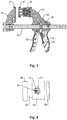
- the structure form of a type of clamp is as shown in figs. 1-3 , which is an F clamp.
- a first clamping body 01 is provided on a first arm 03
- a second clamping body 02 is provided on a second arm 04
- the first arm 03 is provided with a fixed handle 31 in an integrated extending manner
- the second arm 04 is fixed on a guide rod 05
- the guide rod 05 is provided on the first arm 03 in a penetrating manner
- the first arm 03 is provided with a force-applying handle 32, an unlocking handle 33, a force-applying clamping piece 34 for applying a force to the guide rod, and a locking clamping piece 35 for locking the guide rod on the first arm.
- the force-applying handle 32 is linked with the force-applying clamping piece 34, such that when the force-applying handle and the fixed handle are gripped, the guide rod 05 is caused to slide, and the second arm 04 moves close to the first arm 03; and the unlocking handle 33 is linked with the locking clamping piece 35, such that when the unlocking handle and the fixed handle are gripped, a locking of the locking clamping piece on the guide rod is released, for releasing the clamping.
- a first clamping body 01 is provided on a first arm 03
- a second clamping body 02 is provided on a second arm 04
- the first arm 03 is connected with a clamping handle 36 and an unlocking handle 37
- the second arm 04 is fixed on a guide rod 05
- the guide rod 05 is provided on the first arm 03 in a penetrating manner; clamping can be achieved by operating the clamping handle 36, and unlocking of the clamping can be achieved by operating the unlocking handle 37, for releasing the clamping.
- a first clamping body 01 is provided on a first arm 03
- a second clamping body 02 is provided on a second arm 04
- a first handle 38 is extended from the first arm 03
- a second handle 41 is extended from the second arm 04
- the first arm 03 and the second arm 04 are connected by a pivot 06
- a locking mechanism 07 and an unlocking mechanism 08 are provided between the first handle 38 and the second handle 41
- the locking mechanism is a ratchet-pawl mechanism
- the unlocking mechanism includes a handle.
- the base 14 and the first arm 03 can be made integrally together as shown in fig. 8 .
- the base 14 is assembled on the first arm 03, such that the base, the first clamping body and the elastic elements form an integral structure as shown in fig. 4 and fig. 5 and being independent of other structures of the clamp.
- This independent structure has a relatively small volume, and facilitates circulation between stations when calibrating and adjusting the initial pressure of the elastic element.
- the base 14 shown in figs. 1-3 , 6 and 7 is mounted on the first arm 03 in a snap-fit manner, specifically, the base 14 is provided with a clamping groove 19 as a connecting structure, one side (the lower side as shown in the figures) of the clamping groove is open, and the remaining sides are enclosed, and the base can be conveniently snap-fitted at the mounting position of the base by the opening.
- one end of the first arm which fits the clamping groove is provided with a head fitting with the clamping groove, and a snap-fitting with a certain pre-tightening force is realized by using the elasticity of the material (such as engineering plastics), avoiding separation.
- Such an assembly manner particularly facilities assembly.
- the base 14 shown in fig. 9 is assembled at an end of the first arm 03 by a lateral (a direction perpendicular to the paper surface as shown in the figure) pin bolt, in which case the base is preferably sleeved with the first arm and the pin bolt is provided at the overlapping section between the base and the first arm in a penetrating manner.
- the base 14 shown in fig. 10 is assembled at an end of the first arm 03 by a transverse (left-right direction as shown in the figure) pin bolt, in which case, a flange for the pin bolt to penetrate through can be provided on the base and the first arm.
- first clamping body and the second clamping body are determined by reference signs, but practical implementation is not limited to such representation forms, and the positions of the first clamping body and the second clamping body may be exchanged, which can also embody the concept of some embodiments of the present disclosure.
Landscapes
- Engineering & Computer Science (AREA)
- Mechanical Engineering (AREA)
- Chemical & Material Sciences (AREA)
- Analytical Chemistry (AREA)
- Physics & Mathematics (AREA)
- General Physics & Mathematics (AREA)
- Clamps And Clips (AREA)
- Force Measurement Appropriate To Specific Purposes (AREA)
- Gripping Jigs, Holding Jigs, And Positioning Jigs (AREA)
Applications Claiming Priority (2)
| Application Number | Priority Date | Filing Date | Title |
|---|---|---|---|
| CN201910026507.7A CN111434462B (zh) | 2019-01-11 | 2019-01-11 | 可视夹紧力装置及夹具 |
| PCT/CN2019/128334 WO2020143453A1 (zh) | 2019-01-11 | 2019-12-25 | 可视夹紧力装置及夹具 |
Publications (3)
| Publication Number | Publication Date |
|---|---|
| EP3909718A1 true EP3909718A1 (de) | 2021-11-17 |
| EP3909718A4 EP3909718A4 (de) | 2022-09-07 |
| EP3909718B1 EP3909718B1 (de) | 2025-01-08 |
Family
ID=71520858
Family Applications (1)
| Application Number | Title | Priority Date | Filing Date |
|---|---|---|---|
| EP19908877.4A Active EP3909718B1 (de) | 2019-01-11 | 2019-12-25 | Vorrichtung und klemme mit sichtbarer klemmkraft |
Country Status (5)
| Country | Link |
|---|---|
| US (1) | US11559874B2 (de) |
| EP (1) | EP3909718B1 (de) |
| JP (1) | JP7353367B2 (de) |
| CN (1) | CN111434462B (de) |
| WO (1) | WO2020143453A1 (de) |
Cited By (1)
| Publication number | Priority date | Publication date | Assignee | Title |
|---|---|---|---|---|
| EP3842183A1 (de) | 2019-12-23 | 2021-06-30 | WISTRA GmbH Cargo Control | Klemmvorrichtung |
Families Citing this family (6)
| Publication number | Priority date | Publication date | Assignee | Title |
|---|---|---|---|---|
| DE102020127038A1 (de) * | 2020-10-14 | 2022-04-14 | Bessey Tool Gmbh & Co. Kg | Zwingenwerkzeugvorrichtung |
| IT202100012104A1 (it) * | 2021-05-11 | 2022-11-11 | Leonardo Spa | Attrezzo di test per verificare il profilo di un componente strutturale e metodo per testare la conformita' di un profilo di un componente strutturale ad una specifica tolleranza |
| CN113884230B (zh) * | 2021-09-29 | 2024-07-05 | 歌尔科技有限公司 | 一种头戴设备的夹持力测量装置 |
| JP7174464B1 (ja) | 2022-06-17 | 2022-11-17 | イーグルクランプ株式会社 | ねじ式クランプ |
| CN115823359A (zh) * | 2022-12-29 | 2023-03-21 | 浙江金仪盛世生物工程有限公司 | 一种卡箍及输送管路 |
| AT527953A1 (de) * | 2024-02-13 | 2025-08-15 | Trumpf Maschinen Austria Gmbh & Co Kg | Haltevorrichtung für eine Biegemaschine zum Halten eines Biegewerkstücks |
Family Cites Families (28)
| Publication number | Priority date | Publication date | Assignee | Title |
|---|---|---|---|---|
| GB8710129D0 (en) * | 1987-04-29 | 1987-06-03 | Rhombus Tools Ltd | Clamp |
| JPH09300228A (ja) * | 1996-05-14 | 1997-11-25 | Sumitomo Rubber Ind Ltd | シート展張用バイス |
| JPH1182650A (ja) * | 1997-09-12 | 1999-03-26 | Toshiba Corp | ベルト張力調整治具及びベルト張力調整方法 |
| JP4793709B2 (ja) | 2001-01-11 | 2011-10-12 | イーグルクランプ株式会社 | ネジ式クランプ |
| US20030201592A1 (en) * | 2002-04-26 | 2003-10-30 | Rich Cummines | Apparatus and method for a compression spindle assembly for clamping |
| ES2318223T3 (es) * | 2004-08-26 | 2009-05-01 | SCHUNK GMBH & CO. KG SPANN- UND GREIFTECHNIK | Mandril de sujecion con medios de sujecion interiores. |
| DE202008000295U1 (de) | 2008-01-02 | 2008-03-13 | Hsieh, Chih-Ching | Die sensorische Konstruktion eines Spannmittels |
| US20090179363A1 (en) * | 2008-01-16 | 2009-07-16 | Ferng-Jong Liou | Transmission mechanism for clamping device |
| CN101518891B (zh) * | 2008-02-28 | 2012-04-18 | 申普金属工业有限公司 | 手持式快速夹具 |
| JP2010163277A (ja) * | 2009-01-19 | 2010-07-29 | Elephant Chain Block Co Ltd | クランプ |
| CN201613512U (zh) * | 2009-11-06 | 2010-10-27 | 成都飞机工业(集团)有限责任公司 | 一种可显示夹紧力的弓形夹 |
| JP5337743B2 (ja) | 2010-03-03 | 2013-11-06 | 株式会社スーパーツール | クランプ |
| CN102069456B (zh) * | 2010-11-25 | 2013-05-01 | 杭州巨星工具有限公司 | 增力夹具 |
| CN202062318U (zh) * | 2010-12-15 | 2011-12-07 | 杭州巨星科技股份有限公司 | 弹簧夹 |
| FR2982516B1 (fr) * | 2011-11-16 | 2013-11-22 | Peugeot Citroen Automobiles Sa | Systeme de serrage d'une tole pour le controle de la conformite de la tole |
| US20130263674A1 (en) * | 2012-04-05 | 2013-10-10 | ENGINEERED PRODUCT SUPPLY, LLC, d/b/a/ EPS | Tube or pipe clamp with a force measurement device |
| CN203236369U (zh) * | 2013-04-28 | 2013-10-16 | 北京航天光华电子技术有限公司 | 一种快速夹紧卡兰 |
| US9144890B2 (en) | 2013-12-20 | 2015-09-29 | Chung Li Chen | Bar clamp having a ratchet mechanism for fastening a clamped work piece |
| CN203901149U (zh) * | 2014-06-10 | 2014-10-29 | 成都飞机工业(集团)有限责任公司 | 一种c形定力夹紧装置 |
| US9759617B2 (en) * | 2015-04-10 | 2017-09-12 | The Boeing Company | Tool with over pressure indicator and lockout |
| FR3047681B1 (fr) * | 2016-02-17 | 2018-07-27 | Latecoere | Presse de serrage mecanique a dynamometre |
| CN205950322U (zh) * | 2016-07-25 | 2017-02-15 | 广东百事泰电子商务股份有限公司 | 可调节夹具 |
| DE102016015047B4 (de) * | 2016-12-16 | 2021-09-16 | SUER Nutzfahrzeugtechnik GmbH & Co. KG | Teleskopbalken zum Sichern von Ladegut |
| CN206748604U (zh) * | 2017-03-06 | 2017-12-15 | 陈浩楠 | 一种客票计数打孔钳 |
| CN208068070U (zh) * | 2017-11-12 | 2018-11-09 | 江苏瑞尔隆鼎实业有限公司 | 一种新型铝管机外装夹夹具 |
| CN207900207U (zh) * | 2018-03-02 | 2018-09-25 | 东莞理工学院 | 一种工装夹具 |
| CN208132750U (zh) * | 2018-04-27 | 2018-11-23 | 杨惠萍 | 一种叠层片式电感器卸料设备 |
| CN209615234U (zh) * | 2019-01-11 | 2019-11-12 | 杭州巨星科技股份有限公司 | 可视夹紧力装置及夹具 |
-
2019
- 2019-01-11 CN CN201910026507.7A patent/CN111434462B/zh active Active
- 2019-12-25 JP JP2021529743A patent/JP7353367B2/ja active Active
- 2019-12-25 US US17/295,460 patent/US11559874B2/en active Active
- 2019-12-25 WO PCT/CN2019/128334 patent/WO2020143453A1/zh not_active Ceased
- 2019-12-25 EP EP19908877.4A patent/EP3909718B1/de active Active
Cited By (1)
| Publication number | Priority date | Publication date | Assignee | Title |
|---|---|---|---|---|
| EP3842183A1 (de) | 2019-12-23 | 2021-06-30 | WISTRA GmbH Cargo Control | Klemmvorrichtung |
Also Published As
| Publication number | Publication date |
|---|---|
| JP2022516691A (ja) | 2022-03-02 |
| US11559874B2 (en) | 2023-01-24 |
| JP7353367B2 (ja) | 2023-09-29 |
| WO2020143453A1 (zh) | 2020-07-16 |
| US20220001517A1 (en) | 2022-01-06 |
| CN111434462B (zh) | 2025-07-25 |
| EP3909718B1 (de) | 2025-01-08 |
| EP3909718A4 (de) | 2022-09-07 |
| CN111434462A (zh) | 2020-07-21 |
Similar Documents
| Publication | Publication Date | Title |
|---|---|---|
| US11559874B2 (en) | Clamping force visualization device and clamp | |
| CN209615234U (zh) | 可视夹紧力装置及夹具 | |
| US4419824A (en) | Digital electrical length measuring instrument | |
| JPH06194103A (ja) | 直線測定装置 | |
| US4765064A (en) | Digital display type measuring instrument | |
| US4805310A (en) | Probe for the measurement of dimensions | |
| EP1460372B1 (de) | Messuhr | |
| US20230126075A1 (en) | Clamping Force Visualization Clamp and Clamping Force Visualization Clamp Combination Device | |
| JPH0316008Y2 (de) | ||
| US2528201A (en) | Clamp | |
| JPS5830163Y2 (ja) | 定圧測定マイクロメ−タ | |
| US2580009A (en) | Adapter for snap gauges | |
| US2283707A (en) | Torque wrench | |
| JP5208808B2 (ja) | 測定器 | |
| CN112407805B (zh) | 传动带张紧量测量装置 | |
| US2937452A (en) | Pitch diameter gauge end caps | |
| US2791033A (en) | Adapter for dial indicators | |
| CN206269740U (zh) | 料边检测仪 | |
| CN214586625U (zh) | 用于光源设备微调旋钮的辅助调节装置 | |
| US2842854A (en) | Comparator having fine adjustment by frame distortion | |
| CN221666816U (zh) | 厚度测量工具 | |
| CN217424615U (zh) | 一种厚度表测量力校准装置 | |
| US4327494A (en) | Linear gauge | |
| JPS6146406Y2 (de) | ||
| US4848140A (en) | Guide device for a test body of a hardness measuring instrument |
Legal Events
| Date | Code | Title | Description |
|---|---|---|---|
| STAA | Information on the status of an ep patent application or granted ep patent |
Free format text: STATUS: THE INTERNATIONAL PUBLICATION HAS BEEN MADE |
|
| PUAI | Public reference made under article 153(3) epc to a published international application that has entered the european phase |
Free format text: ORIGINAL CODE: 0009012 |
|
| STAA | Information on the status of an ep patent application or granted ep patent |
Free format text: STATUS: REQUEST FOR EXAMINATION WAS MADE |
|
| 17P | Request for examination filed |
Effective date: 20210520 |
|
| AK | Designated contracting states |
Kind code of ref document: A1 Designated state(s): AL AT BE BG CH CY CZ DE DK EE ES FI FR GB GR HR HU IE IS IT LI LT LU LV MC MK MT NL NO PL PT RO RS SE SI SK SM TR |
|
| DAV | Request for validation of the european patent (deleted) | ||
| DAX | Request for extension of the european patent (deleted) | ||
| A4 | Supplementary search report drawn up and despatched |
Effective date: 20220810 |
|
| RIC1 | Information provided on ipc code assigned before grant |
Ipc: B25B 5/06 20060101ALI20220804BHEP Ipc: B25B 5/04 20060101ALI20220804BHEP Ipc: G01L 5/00 20060101ALI20220804BHEP Ipc: B25B 5/16 20060101ALI20220804BHEP Ipc: B25B 5/02 20060101AFI20220804BHEP |
|
| STAA | Information on the status of an ep patent application or granted ep patent |
Free format text: STATUS: EXAMINATION IS IN PROGRESS |
|
| 17Q | First examination report despatched |
Effective date: 20240223 |
|
| GRAP | Despatch of communication of intention to grant a patent |
Free format text: ORIGINAL CODE: EPIDOSNIGR1 |
|
| STAA | Information on the status of an ep patent application or granted ep patent |
Free format text: STATUS: GRANT OF PATENT IS INTENDED |
|
| INTG | Intention to grant announced |
Effective date: 20241010 |
|
| GRAS | Grant fee paid |
Free format text: ORIGINAL CODE: EPIDOSNIGR3 |
|
| GRAA | (expected) grant |
Free format text: ORIGINAL CODE: 0009210 |
|
| STAA | Information on the status of an ep patent application or granted ep patent |
Free format text: STATUS: THE PATENT HAS BEEN GRANTED |
|
| AK | Designated contracting states |
Kind code of ref document: B1 Designated state(s): AL AT BE BG CH CY CZ DE DK EE ES FI FR GB GR HR HU IE IS IT LI LT LU LV MC MK MT NL NO PL PT RO RS SE SI SK SM TR |
|
| REG | Reference to a national code |
Ref country code: GB Ref legal event code: FG4D |
|
| REG | Reference to a national code |
Ref country code: CH Ref legal event code: EP |
|
| REG | Reference to a national code |
Ref country code: DE Ref legal event code: R096 Ref document number: 602019064757 Country of ref document: DE |
|
| REG | Reference to a national code |
Ref country code: IE Ref legal event code: FG4D |
|
| REG | Reference to a national code |
Ref country code: LT Ref legal event code: MG9D |
|
| REG | Reference to a national code |
Ref country code: NL Ref legal event code: MP Effective date: 20250108 |
|
| REG | Reference to a national code |
Ref country code: AT Ref legal event code: MK05 Ref document number: 1758029 Country of ref document: AT Kind code of ref document: T Effective date: 20250108 |
|
| PG25 | Lapsed in a contracting state [announced via postgrant information from national office to epo] |
Ref country code: NL Free format text: LAPSE BECAUSE OF FAILURE TO SUBMIT A TRANSLATION OF THE DESCRIPTION OR TO PAY THE FEE WITHIN THE PRESCRIBED TIME-LIMIT Effective date: 20250108 |
|
| PG25 | Lapsed in a contracting state [announced via postgrant information from national office to epo] |
Ref country code: RS Free format text: LAPSE BECAUSE OF FAILURE TO SUBMIT A TRANSLATION OF THE DESCRIPTION OR TO PAY THE FEE WITHIN THE PRESCRIBED TIME-LIMIT Effective date: 20250408 |
|
| PG25 | Lapsed in a contracting state [announced via postgrant information from national office to epo] |
Ref country code: FI Free format text: LAPSE BECAUSE OF FAILURE TO SUBMIT A TRANSLATION OF THE DESCRIPTION OR TO PAY THE FEE WITHIN THE PRESCRIBED TIME-LIMIT Effective date: 20250108 |
|
| PG25 | Lapsed in a contracting state [announced via postgrant information from national office to epo] |
Ref country code: PL Free format text: LAPSE BECAUSE OF FAILURE TO SUBMIT A TRANSLATION OF THE DESCRIPTION OR TO PAY THE FEE WITHIN THE PRESCRIBED TIME-LIMIT Effective date: 20250108 |
|
| PG25 | Lapsed in a contracting state [announced via postgrant information from national office to epo] |
Ref country code: ES Free format text: LAPSE BECAUSE OF FAILURE TO SUBMIT A TRANSLATION OF THE DESCRIPTION OR TO PAY THE FEE WITHIN THE PRESCRIBED TIME-LIMIT Effective date: 20250108 |
|
| PG25 | Lapsed in a contracting state [announced via postgrant information from national office to epo] |
Ref country code: NO Free format text: LAPSE BECAUSE OF FAILURE TO SUBMIT A TRANSLATION OF THE DESCRIPTION OR TO PAY THE FEE WITHIN THE PRESCRIBED TIME-LIMIT Effective date: 20250408 Ref country code: IS Free format text: LAPSE BECAUSE OF FAILURE TO SUBMIT A TRANSLATION OF THE DESCRIPTION OR TO PAY THE FEE WITHIN THE PRESCRIBED TIME-LIMIT Effective date: 20250508 |
|
| PG25 | Lapsed in a contracting state [announced via postgrant information from national office to epo] |
Ref country code: HR Free format text: LAPSE BECAUSE OF FAILURE TO SUBMIT A TRANSLATION OF THE DESCRIPTION OR TO PAY THE FEE WITHIN THE PRESCRIBED TIME-LIMIT Effective date: 20250108 |
|
| PG25 | Lapsed in a contracting state [announced via postgrant information from national office to epo] |
Ref country code: LV Free format text: LAPSE BECAUSE OF FAILURE TO SUBMIT A TRANSLATION OF THE DESCRIPTION OR TO PAY THE FEE WITHIN THE PRESCRIBED TIME-LIMIT Effective date: 20250108 Ref country code: PT Free format text: LAPSE BECAUSE OF FAILURE TO SUBMIT A TRANSLATION OF THE DESCRIPTION OR TO PAY THE FEE WITHIN THE PRESCRIBED TIME-LIMIT Effective date: 20250508 |
|
| PG25 | Lapsed in a contracting state [announced via postgrant information from national office to epo] |
Ref country code: BG Free format text: LAPSE BECAUSE OF FAILURE TO SUBMIT A TRANSLATION OF THE DESCRIPTION OR TO PAY THE FEE WITHIN THE PRESCRIBED TIME-LIMIT Effective date: 20250108 Ref country code: GR Free format text: LAPSE BECAUSE OF FAILURE TO SUBMIT A TRANSLATION OF THE DESCRIPTION OR TO PAY THE FEE WITHIN THE PRESCRIBED TIME-LIMIT Effective date: 20250409 |
|
| PG25 | Lapsed in a contracting state [announced via postgrant information from national office to epo] |
Ref country code: AT Free format text: LAPSE BECAUSE OF FAILURE TO SUBMIT A TRANSLATION OF THE DESCRIPTION OR TO PAY THE FEE WITHIN THE PRESCRIBED TIME-LIMIT Effective date: 20250108 |
|
| PG25 | Lapsed in a contracting state [announced via postgrant information from national office to epo] |
Ref country code: SE Free format text: LAPSE BECAUSE OF FAILURE TO SUBMIT A TRANSLATION OF THE DESCRIPTION OR TO PAY THE FEE WITHIN THE PRESCRIBED TIME-LIMIT Effective date: 20250108 |
|
| PG25 | Lapsed in a contracting state [announced via postgrant information from national office to epo] |
Ref country code: SM Free format text: LAPSE BECAUSE OF FAILURE TO SUBMIT A TRANSLATION OF THE DESCRIPTION OR TO PAY THE FEE WITHIN THE PRESCRIBED TIME-LIMIT Effective date: 20250108 |
|
| REG | Reference to a national code |
Ref country code: DE Ref legal event code: R097 Ref document number: 602019064757 Country of ref document: DE |
|
| PG25 | Lapsed in a contracting state [announced via postgrant information from national office to epo] |
Ref country code: DK Free format text: LAPSE BECAUSE OF FAILURE TO SUBMIT A TRANSLATION OF THE DESCRIPTION OR TO PAY THE FEE WITHIN THE PRESCRIBED TIME-LIMIT Effective date: 20250108 |
|
| PG25 | Lapsed in a contracting state [announced via postgrant information from national office to epo] |
Ref country code: EE Free format text: LAPSE BECAUSE OF FAILURE TO SUBMIT A TRANSLATION OF THE DESCRIPTION OR TO PAY THE FEE WITHIN THE PRESCRIBED TIME-LIMIT Effective date: 20250108 Ref country code: CZ Free format text: LAPSE BECAUSE OF FAILURE TO SUBMIT A TRANSLATION OF THE DESCRIPTION OR TO PAY THE FEE WITHIN THE PRESCRIBED TIME-LIMIT Effective date: 20250108 |
|
| PG25 | Lapsed in a contracting state [announced via postgrant information from national office to epo] |
Ref country code: RO Free format text: LAPSE BECAUSE OF FAILURE TO SUBMIT A TRANSLATION OF THE DESCRIPTION OR TO PAY THE FEE WITHIN THE PRESCRIBED TIME-LIMIT Effective date: 20250108 |
|
| PG25 | Lapsed in a contracting state [announced via postgrant information from national office to epo] |
Ref country code: SK Free format text: LAPSE BECAUSE OF FAILURE TO SUBMIT A TRANSLATION OF THE DESCRIPTION OR TO PAY THE FEE WITHIN THE PRESCRIBED TIME-LIMIT Effective date: 20250108 |
|
| PLBE | No opposition filed within time limit |
Free format text: ORIGINAL CODE: 0009261 |
|
| STAA | Information on the status of an ep patent application or granted ep patent |
Free format text: STATUS: NO OPPOSITION FILED WITHIN TIME LIMIT |
|
| 26N | No opposition filed |
Effective date: 20251009 |
|
| PGFP | Annual fee paid to national office [announced via postgrant information from national office to epo] |
Ref country code: GB Payment date: 20251229 Year of fee payment: 7 |
|
| PGFP | Annual fee paid to national office [announced via postgrant information from national office to epo] |
Ref country code: IT Payment date: 20251210 Year of fee payment: 7 |
|
| PGFP | Annual fee paid to national office [announced via postgrant information from national office to epo] |
Ref country code: FR Payment date: 20251230 Year of fee payment: 7 |
|
| PGFP | Annual fee paid to national office [announced via postgrant information from national office to epo] |
Ref country code: DE Payment date: 20251231 Year of fee payment: 7 |